investigation of the critical submergence at pump intakes · pdf file ·...
TRANSCRIPT

Investigation of the critical submergence at pump intakes based on multiphase CFD calculations
P. Pandazis & F. Blömeling TÜV NORD SysTec GmbH and Co. KG, Germany
Abstract
Surface vortices occur at pump intakes, when the water-level sinks below a critical value. They can affect the intake flow in a disadvantageous manner. Pump disturbances may be initiated and the mass flow may be decreased or completely interrupted. The determination of the critical value to avoid surface vortices is an important part of safety analyses of postulated abnormal operations and accidents in Light Water Reactors. The vortex formation phenomena are investigated within the research project “Generic numerical determination of the critical submergence at pump intakes to avoid gas entrainment” sponsored by the German Federal Ministry of Economics and Technology. In this project a coupled numerical-analytical method has been developed to calculate the critical submergence. The method is based on the results of two-phase numerical CFD simulations and on the analytical vortex model of Burgers and Rott. It allows an efficient investigation of various influence parameters, which affect the critical submergence. The results of the method are compared with the experimental results from Jain et al. and Moriya and show a very good agreement. The present paper describes the performed CFD simulations as well as some validation results. Keywords: critical submergence, multiphase vortex simulation, CFD, coupled method.
1 Introduction
Surface vortices at pump intakes are particularly generated by the pressure drop resulting from pump suction and disturbances in the approaching flow. When the submergence drops below a critical value a small dip on the water surface can be
www.witpress.com, ISSN 1743-3533 (on-line) WIT Transactions on Engineering Sciences, Vol 82, © 2014 WIT Press
doi:10.2495/AFM140131
Advances in Fluid Mechanics X 143
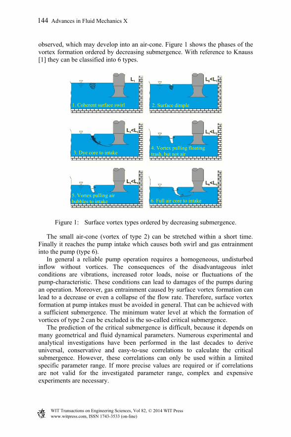
observed, which may develop into an air-cone. Figure 1 shows the phases of the vortex formation ordered by decreasing submergence. With reference to Knauss [1] they can be classified into 6 types.
Figure 1: Surface vortex types ordered by decreasing submergence.
The small air-cone (vortex of type 2) can be stretched within a short time. Finally it reaches the pump intake which causes both swirl and gas entrainment into the pump (type 6). In general a reliable pump operation requires a homogeneous, undisturbed inflow without vortices. The consequences of the disadvantageous inlet conditions are vibrations, increased rotor loads, noise or fluctuations of the pump-characteristic. These conditions can lead to damages of the pumps during an operation. Moreover, gas entrainment caused by surface vortex formation can lead to a decrease or even a collapse of the flow rate. Therefore, surface vortex formation at pump intakes must be avoided in general. That can be achieved with a sufficient submergence. The minimum water level at which the formation of vortices of type 2 can be excluded is the so-called critical submergence. The prediction of the critical submergence is difficult, because it depends on many geometrical and fluid dynamical parameters. Numerous experimental and analytical investigations have been performed in the last decades to derive universal, conservative and easy-to-use correlations to calculate the critical submergence. However, these correlations can only be used within a limited specific parameter range. If more precise values are required or if correlations are not valid for the investigated parameter range, complex and expensive experiments are necessary.
1. Coherent surface swirl 2. Surface dimple
3. Dye core to intake
5. Vortex pulling air bubbles to intake
4. Vortex pulling floating trash, but not air
6. Full air core to intake
www.witpress.com, ISSN 1743-3533 (on-line) WIT Transactions on Engineering Sciences, Vol 82, © 2014 WIT Press
144 Advances in Fluid Mechanics X
So far, various numerical studies were completed on the basis of the experimental results from Moriya at TÜV NORD SysTec GmbH and Co. KG Hamburg. Based on these studies a combined analytical-numerical method has been developed for the calculation of the vortex-core lengths. Moreover, through further investigations this combined method has been extended by an effective approach to calculate the critical submergence on a wide parameter range. In the present paper the validation process of both the CFD code and the combined method is described. Computed tangential velocity fields and gas core lengths are compared with measurements from Moriya. The experimental data of Jain et al. [5] is used to validate the numerically determined critical submergences for various parameters.
2 The combined method
Surface vortices consist basically of two different regions, a strongly rotational vortex core and a free vortex region outside the core region [1]. By using the CFD Code ANSYS CFX [3] it is possible to compute the flow field in the free vortex region efficiently and in good approximation. However, a proper resolution of the vortex core region needs much more effort. Therefore, the basic concept of the combined method is the application of the analytical vortex model in the core region and the usage of CFX in the free vortex parts. The vortex model of Burgers and Rott depends on two parameters which have to be obtained from the CFD data. This combined method based on multiphase CFD calculations and the analytical vortex model of Burgers and Rott allows the efficient calculation of the gas-core length and the critical submergence. In the following the combined method is described and its effectiveness is demonstrated by the recalculation of the experimental results of Moriya s experiment.
2.1 Analytical model from Burgers and Rott
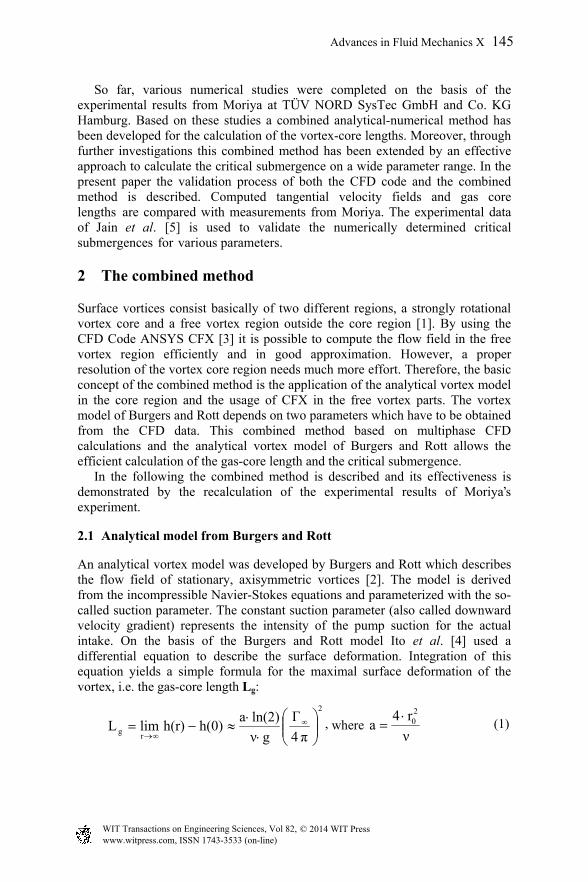
An analytical vortex model was developed by Burgers and Rott which describes the flow field of stationary, axisymmetric vortices [2]. The model is derived from the incompressible Navier-Stokes equations and parameterized with the so-called suction parameter. The constant suction parameter (also called downward velocity gradient) represents the intensity of the pump suction for the actual intake. On the basis of the Burgers and Rott model Ito et al. [4] used a differential equation to describe the surface deformation. Integration of this equation yields a simple formula for the maximal surface deformation of the vortex, i.e. the gas-core length Lg:
2
rg π4
Γ
gν
ln(2)ah(0)h(r)limL
, where
ν
r4a
20 (1)
www.witpress.com, ISSN 1743-3533 (on-line) WIT Transactions on Engineering Sciences, Vol 82, © 2014 WIT Press
Advances in Fluid Mechanics X 145
’

In eqn (1) h characterizes the submergence, υ the viscosity, g the gravitational acceleration, r the radial coordinate, r0 the specific vortex-core radius, ∞ the circulation and a the suction parameter. Obviously the usage of this analytical model requires the knowledge of the suction parameter and the circulation. But measuring as well as the prediction of these parameters is quite difficult. How these two parameters can be determined with CFD simulations will be demonstrated in the succeeding paragraphs.
2.2 CFD model of Moriya’s experiments
Moriya investigated swirling vortex formation in an open cylindrical vessel (Ito et al. [4]). Figure 2 shows the setup of the test equipment. The water is drained through a central, vertical pump intake and reinjected tangentially through an inlet slit on the side of the tank. This configuration enables the measurements of surface vortices at a constant water level with different mass flows. The mass flow was gradually increased until the gas-core of the generated surface vortex reaches the pump intake. The gas-core lengths as well as the velocity fields were measured for different mass flows at a constant water level of 500 mm.
Figure 2: The setup of the experiment of Moriya and the corresponding CFD model.
During the measurements a stationary but non-axisymmetric vortex developed. Therefore, it was necessary to model the whole test vessel. To model the free-surface also the air above the surface had to be considered in the model. Thus, a 50 mm high cylindrical domain filled with air has been placed above the water surface. The height of the domain ensures enough distance of the interface to the upper boundary conditions to eliminate any feedback of the boundary conditions on the free surface.
velocity inlet
interface
mass flow outlet
water
air, 1 bar
www.witpress.com, ISSN 1743-3533 (on-line) WIT Transactions on Engineering Sciences, Vol 82, © 2014 WIT Press
146 Advances in Fluid Mechanics X

CFX provides two Eulerian-Eulerian models for multiphase flow, the homogeneous and the inhomogeneous model [3]. The homogeneous model assumes mechanical equilibrium between the phases, i.e. water and air share one velocity field, whereas the inhomogeneous model solves phase specific momentum equations by introducing the volume fractions in the conservation equations. Preliminary calculations have shown that the homogenous model yields a smeared interface for strong surface deformations which makes the precise calculation of the gas-core length difficult. Therefore, the more complex inhomogeneous phase model has been chosen which leads to improved convergence and a sharper interface. Regarding the interaction of the phases, only momentum exchange had to be considered by a transfer term in the momentum equation, because no mass or energy transfer took place between water and air in this experiment. The interphase momentum transfer is modelled with the drag force. In the present case the drag coefficient was a constant value of 0.44 according to Newton’s drag law. To model the turbulence a turbulence model was needed. Three different turbulence models were tested in our preliminary studies. First the two equation eddy viscosity model SST was applied. Next it was combined with an algebraic curvature correction approach to consider the strongly swirling flow in the test section (SST-CC). The third candidate was the second-order Reynolds stress model SSG [3] which determines all components of the Reynolds stress tensor. The tangential velocities computed with the SST-CC model showed the best agreement with the experimental results. Therefore, this model was used for the following calculations. The numerical grid was generated from hexahedral elements. The mesh was refined at the walls, at the water surface and in the vortex core. Air and water enter the tank separately through the inlet slit with equal velocities to avoid undesired disturbances on the free surface at the inlet. The outlet boundary condition at the intake is a given mass flow for the liquid phase. On top of the model is an opening condition at atmospheric pressure.
2.3 Results of the combined method
The calculations were repeated with the aforementioned model setup with three different volume flow rates: 25, 50 and 100 l/s. In every run the gas-core length was determined directly from the CFX results by evaluating the deformation of the interface. Moreover, the circulation and the suction parameter which are required in the combined method were obtained as follows. The suction parameter describes the averaged downward velocity gradient. Its local values are available from CFX, because CFX calculates the velocity gradients for all mesh cells. These local downward velocity gradients have been averaged along the vortex core boundary in the vicinity of the free surface to obtain the suction parameter. The boundary of the vortex core was determined by the Q-criteria [2]. The circulation was computed by integrating the tangential velocities along a closed curve far away from the vortex-core.
www.witpress.com, ISSN 1743-3533 (on-line) WIT Transactions on Engineering Sciences, Vol 82, © 2014 WIT Press
Advances in Fluid Mechanics X 147

Figure 3: Gas-core lengths for different volume flows.
The measured and calculated gas-core lengths are presented in figure 3. It is clearly visible that the CFX results strongly underestimate the gas-core lengths especially for strong surface deformations. Former studies showed that further improvements of the CFX results demand a significantly higher computational effort. In contrary the combined method which is based on the same CFX results, shows a very good agreement with the experimental data with nearly no additional effort.
3 Determination of the critical submergence
Using the fact that the combined method calculates the gas-core lengths properly the prediction of the critical submergence is possible also. With the combined method it is possible to determine the critical submergence for one set of operation conditions with a minimum of two CFX simulations. This is explained in section 3.1. In section 3.2 it is shown how this procedure can be extended to allow the computation of the critical submergence also for other operation conditions without any further CFD analysis. This advanced combined method has been used to calculate the critical submergence for various intake velocities and circulations. Furthermore, it was validated against the experimental results of Jain et al.
3.1 Application of the combined method
Exactly when the critical submergence is reached the gas-core length of the vortex above the pump intake becomes larger than zero. However, for numerical reasons the critical submergence is detected in the following, when the gas-core length reaches a threshold of 1 mm. In general, the corresponding water level is unknown. Therefore, at least two CFX analyses are necessary whose boundary conditions are chosen such that
www.witpress.com, ISSN 1743-3533 (on-line) WIT Transactions on Engineering Sciences, Vol 82, © 2014 WIT Press
148 Advances in Fluid Mechanics X

they enclose the conditions for the critical submergence. From these simulations one obtains at least two pairs of water levels and gas-core lengths which yield the critical submergence by interpolation. Following the same strategy it is also possible to determine the suction parameter which corresponds to the critical submergence. This critical suction parameter can then be used to compute the critical submergence for other operation conditions without further CFD simulations. The corresponding procedure is called advanced, combined method and is described in the next section.
3.2 Advanced combined method
The advanced combined method is based on the following idea: If the critical submergence is known for one set of boundary conditions, equation (1) should apply to calculate the critical submergence for other operation conditions. First it is necessary to determine the critical suction parameter corresponding to the critical submergence. The suction parameter is obtained by interpolation of the suction parameters from at least two CFD calculations and their corresponding gas-core lengths just as it was done for the critical submergence. Again the threshold of τ = 1 mm was used as critical gas-core length to detect the critical submergence. Previous CFD simulations showed that the vortex core radius varies almost linearly with the height, i.e. the vortex-core radius r0 is proportional to the vertical distance to the intake h. Hence, the relation between r0 and h is given by the expansion constant C in equation (2).
.const
r
hC
0
(2)
By introducing C in equation (1) and using the relation between the suction parameter a and the vortex core radius r0 an analytical correlation for the critical submergence hcrit can be derived (equation (3)).
4
1
crit gτ
ln(2)
ρπ2
tanmCh
(3)
In equation (3) ṁ is the mass flow, φ the inflow angle and ρ the fluid density. Thus, equation (3) provides a simple analytical correlation to calculate the critical submergence for various intake velocities assuming constant density and inflow angle.
3.3 CFD model of the Jain et al. experiment
Jain et al. [5] performed experiments to investigate the influence of several parameters on the critical submergence in an open cylindrical vessel with a vertical pump intake. Figure 4 shows the setup of the experiment and the corresponding CFD model. The test vessel was drained with constant mass flow rates. The water was pumped back into the tank along its circumference via adjustable guided vanes to adjust an exact inflow angle. During the experiment
www.witpress.com, ISSN 1743-3533 (on-line) WIT Transactions on Engineering Sciences, Vol 82, © 2014 WIT Press
Advances in Fluid Mechanics X 149

Figure 4: Experimental setup by Jain et al. and the corresponding CFD model.
the water level was decreased stepwise until the air-core of the vortex reached the intake. The stationary surface vortices arose in the centre of the vessel. Thus, to reduce the computational effort only a 1.5 degree thin section has been modelled with periodic boundary conditions at the cut planes. As a further simplification the inflow angle was directly imposed at the inlet. So, it was not necessary to model the guide vanes. The computational cell sizes as well as the setup of the CFD model were based on model studies performed for Moriya’s experiment (see section 2.2). During the experiments the critical submergence was measured for several intake velocities, inflow angles, viscosities, surface tensions and intake diameters. The simulations considered three different inflow angles for an intake velocity range which was even larger than in the experiments. For all inflow angles the critical submergence was calculated with the advanced combined method described above.
3.4 Validation results
The experimental and the calculated results are presented in figure 5. In a first step the critical submergence was determined for one operation point with the combined method (see section 3.1). The interpolation of the results of two CFD analyses is marked with a spot in figure 5. In the same way the critical suction parameter and the expansion constant were obtained from the CFD simulations. Starting from this point the critical submergence was calculated with equation (3) on the whole intake velocity range from 0.5 to 5 m/s. This advanced combined method was performed with inflow angles of 20, 45 and 60 degree. The calculated critical submergences are in very good
www.witpress.com, ISSN 1743-3533 (on-line) WIT Transactions on Engineering Sciences, Vol 82, © 2014 WIT Press
150 Advances in Fluid Mechanics X

Figure 4: Critical submergence obtained by Jain’s experiment and by the advanced combined method.
coincidence with the experimental data for all investigated inflow angles. Thus, as a conclusion it can be stated that the advanced combined method is successfully validated regarding the calculation of the critical submergence for the avoidance of surface vortices.
4 Conclusions
A multiphase CFD model has been developed to investigate surface vortices at vertical pump intakes. Although it is possible to compute the flow field outside the vortex core with comparatively small effort the costs increase significantly if one aims to compute the whole flow field including the vortex core. For this reason the CFD model was combined with the analytical vortex model of Burgers and Rott which allows the efficient computation of the tangential velocities also in the vortex core region and the gas-core length. However, the Burgers-Rott model requires the knowledge of the so-called suction parameter and the circulation of the flow. Both are determined from the CFD results outside of the vortex-core region. The results calculated with this combined method agree well with the experimental results of Moriya. The aforementioned combined method is also capable to determine the critical submergence for a given set of operation conditions based on at least two CFD simulations. Moreover, this method has been extended by an analytical approach which enables the calculation of the critical submergence for a wide parameter range without further CFD analyses. The critical submergences were
www.witpress.com, ISSN 1743-3533 (on-line) WIT Transactions on Engineering Sciences, Vol 82, © 2014 WIT Press
Advances in Fluid Mechanics X 151

predicted with the resulting advanced combined method for different inflow angles and intake velocities. The comparison of the results with experimental data from Jain et al. showed a very good agreement.
Acknowledgements
This work is sponsored by the German Federal Ministry of Economics and Technology (BMWi) under the contract number 1501410. The responsibility for the content of this publication lies with the authors.
References
[1] J. Knauss, Swirling Flow Problems at Intake, IAHR Hydraulic Structures Design Manual, 1987.
[2] J.-Z. Wu, H.-Y. Ma, M.-D. Zhou, Vorticity and Vortex Dynamics, Springer-Verlag, 2006.
[3] ANSYS Germany GmbH., ANSYS CFX Users Manual, www.ansys.com [4] K. Ito, T. Sakai, Y. Eguchi, H. Monji, H. Ohshima, A. Uchibori, Y. Xu,
Improvement of Gas Entrainment Prediction Method –Introduction of Surface Tension Effect-, Journal of Nuclear Science and Technology, Vol. 47, No. 9, 771-778 2010.
[5] A.K. Jain, K.G. Ranga Raju, R.J. Garde, Vortex Formation at Vertical Pipe Intakes, Journal of the Hydraulic Division, 1978.
www.witpress.com, ISSN 1743-3533 (on-line) WIT Transactions on Engineering Sciences, Vol 82, © 2014 WIT Press
152 Advances in Fluid Mechanics X