investigation of surface modification on aluminum oxide ...umpir.ump.edu.my/4460/1/cd6598_66.pdf ·...
TRANSCRIPT

INVESTIGATION OF SURFACE MODIFICATION ON ALUMINUM OXIDE
USING ACID ETCHING SURFACE PRETREATMENT
MOHD IDHAM BIN ROSMAN
A report submitted in partial fulfillment of
The requirements for the award of the degree of
Bachelor of Mechanical Engineering With Manufacturing Engineering
Faculty of Mechanical Engineering
Universiti Malaysia Pahang
JUNE 2012

viii
ABSTRACT
The current work focus on surface modification of aluminum oxide using acid etching
surface pre-treatment. The main objective of this thesis is to investigate the effect of
surface pre-treatment using acid etching on aluminum oxide (Al2O3) cutting tool. The
effect of machining performance on alumina cutting tool using this pre-treatment in
term of wear rate also studied. The scope of work include alumina as cutting tool, acid
hydrofluoric for etching, PVD coating process and machining by turning operation.
Alumina cutting tool was subjected to acid etching surface pre-treatment for 20 minutes
before it was deposited with PVD coating process. Next, the cutting tool was test by
turning machine in order to determine the wear resistant and other material
characterization also was performed such as microstructure study, hardness Vickers test
and surface roughness test. The current work result show shows a regular rough surface
with no voids and crystals emerging from the as-received surface while a non-uniform
surface topography with peak and valley after pre-treatment. The surface pre-treatment
with HF acid provide rough surface to alumina microstructure. Besides, the machining
test performance shows the coated alumina with acid etching surface pre-treatment
provided longer tool’s life compared to as- received alumina and coated alumina
without pre-treatment cutting tools. In addition, the micro hardness test indicated that
average Vickers micro hardness of alumina as-received specimen was 1202.47 HV
while coated alumina with acid etching pre-treatment specimen was 2293.43 HV. In
surface roughness test, the surface roughness of alumina increase after subjected to pre-
treatment but decrease after endergoes coating process. From the result, the acid etching
surface pre-treatment and coating process affect the mechanical properties of alumina
cutting tool such as microstructure, wear resistance, hardness and surface roughness.
ix
ABSTRAK
Kerja ini membentangkan kajian pengubahsuaian pada permukaan aluminium oksida
dengan menggunakan asid sebagai pra-rawatan pada pemukaan. Objektif utama tesis ini
adalah untuk mengkaji kesan pra-rawatan menggunakan asid pada aluminium oksida
(Al2O3). Kesan prestasi alat pemotong alumina dengan menggunakan pra-rawatan ini
diuji dengan mesin untuk melihat sejauh mana kadar jangka hayatnya dapat bertahan.
Skop kerja termasuklah alumina sebagai alat pemoting, asid hydruoflouric untu pra-
rawatan, proses salutan PVD dan proses pemesinan. Alat pemotong alumina direndam
dalam pra-rawatan asid selama 20 minit. dan proses salutan PVD dilakukan. Alat
pemotong alumina diuji dengan mesin untuk melihat kadar jangka hayatnya serta ujian
lain seperti mikrostruktur, kekerasan dan kekasaran permukaan. Keputusan
menunjukkan struktur biasa pada alumina asal manakala struktur yang kasar dengan
puncak dan lembah selepas pra-rawatan dilakukan. Asid HF menghasilkan struktur yang
kasar ke atas alumina. Selain itu, ujian dengan mesin menunjukkan alumina yang
melalui pra-rawatan dan salutan mempunyai kadar jangka masa hayat yang tinggi
berbanding alumina asal dan alumina tanpa pra-rawatan. Tambahan pula ujian
kekerasan Vickers bagi alumina asal ialah 1202.47 HV mankala kekerasan alumina
yang melalui pra-rawatan dan salutan ialah 2293.43 HV. Di dalam ujian kekasaran pula
menunjukkan kekasaran permukaan bertambah selepas pra-rawatan asid tetapi bekurang
selepas menjalani proses salutan. Daripada keputusan ini, ia menunjukkan bahawa pra-
rawatan asid mempengaruhi alumina dari segi mikrostruktur, kadar jangka hayat,
kekuatan dan kekasaran permukaan.

x
TABLE OF CONTENTS
Page
EXAMINER’S APPROVAL DOCUMENT ii
EXAMINER’S DECLARATION iii
SUPERVISOR’S DECLARATION iv
STUDENT’S DECLARATION v
DEDICATION vi
ACKNOWLEDGEMENTS vii
ABSTRACT viii
ABSTRAK ix
TABLE OF CONTENTS xii
LIST OF TABLES xiii
LIST OF FIGURES xiv
LIST OF SYMBOLS xv
LIST OF ABBREVIATIONS xvi
CHAPTER 1 INTRODUCTION
1.1 Project Background 1
1.2 Problem Statement 2
1.3 Objectives 3
1.4 Scopes 3
CHAPTER 2 LITERATURE REVIEW
2.1 Introduction 4
2.2 Cutting Tool 4
2.3 Cutting Tool Material 5
2.3.1 Aluminum Oxide 5
2.3.2 Tungsten Carbide 6
2.4 Tool Wear 7
2.5 Tool Life 9

xi
2.6 Surface Pre-treatment 10
2.6.1 Acid Etching 11
2.6.2 Hydrofluoric Acid 11
2.7 Coating 12
2.8 Coating Technique 14
2.8.1 PVD Process 14
2.8.2 CVD Process 16
2.9 Coating Material 17
2.9.1 Polycrystalline Diamond 18
2.9.2 Diamond like Carbon 18
2.9.3 Hard Carbon 19
2.10 Machining 19
2.10.1 Turning 20
CHAPTER 3 METHODOLOGY
3.1 Introduction 21
3.2 Cutting Tool Material 21
3.3 Surface Pre-treatment Procedure 23
3.4 Microstructure Characterization 23
3.5 PVD Coating Procedure 24
3.6 Machining Procedure 25
3.7 Material Characterization 26
3.7.1 Wear Evaluation 26
3.7.2 Vickers Hardness 26
3.7.3 Surface Roughness 27
CHAPTER 4 RESULT AND DISCUSSION
4.1 Introduction 29
4.2 Effect Acid Etching to Microstructure 29
4.3 Effect Acid Etching to Machining Performance 31
4.4 Effect Acid Etching to Hardness 34
4.5 Effect Acid Etching to Surface Roughness 35

xii
CHAPTER 5 CONCLUSION AND RECOMMENDATIONS
5.1 Conclusion 37
5.2 Recommendations 38
REFERENCES 39
APPENDICES
A Gantt Chart 41
B Tensile Test Result 42
C Standard 45

xiii
LIST OF TABLES
Table No. Page
3.1 Physical properties of alumina 22
3.2 PVD coating parameter 24
3.3 Turning machine parameter 25
xiv
LIST OF FIGURES
Figure No. Page
2.1 Factor of wear 8
2.2 Effect of wear 9
2.3 Effect of cutting speed 10
2.4 Coating microstructures and occurring grain sizes at
various coating thickness
13
2.5 PVD process diagram 15
2.6 CVD process diagram 17
2.7 Force components measured in turning tests 20
3.1 Methodology Flowchart 22
3.2 Scanning electron microscopy model EVO®50 02-73 24
3.3 Shun Chuan turning machine model ERL13370 25
3.4 Optical measurement microscope model QUADRA-CHECK
300 Series
26
3.5 Vickers hardness model MATSUZAWA MMT-X7 27
3.6 Surface roughness tester model Mitutoyo SV- 614 28
4.1 Alumina Microstructure for as-received and after 20 minutes
Acid Etching
31
4.2 Effect of surface pretreatment to flank wear 32
4.3 Effect of different cutting speed to flank wear 33
4.4 Effect of surface pretreatment to hardness 35
4.5 Effect of surface pretreatment to surface roughness 36

xv
LIST OF SYMBOLS
V Cutting speed
Tn Tool life
C Constant
VB Flank wear
A Area
D Diameter
F Force
α Alpha Vickers indenter
p Pressure load

xvi
LIST OF ABBREVIATIONS
SEM Scanning electron microscope
PVD Physical vapor deposition
CVD Chemical vapor deposition
HF Hydrofluoric acid
HV Hardness Vickers
TRS Tranverse rupture strength
IP Ion plating
PCD Polycrystalline diamond
DLC Diamond like carbon
ASTM American society for testing and materials
ISO International standardization organization

CHAPTER 1
INTRODUCTION
1.1 INTRODUCTION
Nowadays, cutting tools industry was going through a big transformation
development. Cutting tools are widely used in turning, shaping, grinding, polishing,
drilling and other engineering applications in different industrial settings (Park, 1999).
Cutting process was defined as removing material by one cutting edge. Cutting
tools condition must be sharped with high hardness and high wear resistant to provided
a long tool life. In order to improve hardness and wear resistant of the cutting tool, some
modification has been taken for example by adding new coatings or new alloys for
design changes. This step is vital to reduce the thermal heat and friction effect during
cutting process in order to increase cutting tools efficiency and enhanced tool life.
According to Suzuki (1983), “Ceramics have attracted considerable attention
since 1950’s because of their excellent properties such as high hardness, high resistance
to chemical corrosion and good mechanical properties at high temperatures”. The most
common ceramic materials are based on aluminum or also known as aluminum oxide
(Al2O3). It was used almost exclusively on turning tool bits. It has several advantages
such as high hardness, high thermal resistant and high chemical resistant (Gruss, 1994).
In addition, it also has disadvantage such as low toughness that makes the cutting tool
more brittle. Nevertheless, this problem can be solved by providing new coating with
surface pr-treatment.
Campestrini (2001) stated that, “The pre-treatment can affect the composition of
the alloyed surface and hence, increase the development of the conversion coatings”.

2
From his findings, the pre-treatment provided the best surface for adhesion and it is
used to provide high surface roughness topography that plays an important role in
biological interactions on tissue interface. The surface changes were suitable for coating
adhesive.
While Elsentriecy (2007) stated that, “Chemical or electrochemical pre-
treatment methods, such as acid activation are capable to removed the oxide layer”.
Therefore, it is believed that acid etching solution roughened the etched surface. The
pre-treatment methods used to remove native oxide layer that does not protect well
against corrosion. It forms easily due to the high reactivity of Magnesium. Acid etching
pre-treatments has several advantages such as provided highly adhering layers and
deposited complex inorganic coatings.
Physical Vapor Deposition process (PVD) is the major process used to produce
cutting tool coatings. According to Wertheim (1998), “The stress characteristics of the
PVD coating, in combination with the usually small layer thickness from 2 to 5 pm,
provided good cutting edge strength, fracture toughness and bending strength”. From
his findings, coating with PVD can contribute to the uniform coating thickness. This
part is important to provide sharp cutting edge on cutting tools.
1.2 PROBLEM STATEMENT
Ceramic cutting tool which is aluminum have attracted considerable attention
since 1950’s because of their excellent properties such as high hardness, high resistance
to chemical corrosion and good mechanical properties at high temperature. However,
their low strength, toughness and low thermal shock resistance limit their application.
This problem weakens the cutting tool for example of tool wear. Traditionally, Cutting
tool improvement has been seen as a solution. In order to solve this problem, the cutting
tools need to be modified using surface pre treatment and coating process. One type of
the surface pre-treatment is acid etching. Acid etching is use to remove the oxide layer
on cutting tool to increase surface adhesion. Uncoated cutting tools show significant
wear resistance capability. Thus, their wear resistance could be improved by coating
process. The application of coating technology into cutting tool can give a lot of

3
improvement in their structure by increase high hardness, increase wear resistant,
increase tool’s life and provided low coefficients of friction. Therefore, the current work
focused on improving the wear resistance of cutting tool which is aluminum in
machining with titanium by turning operation. The main objective of this study is to
increase the aluminum cutting tool’s life.
1.3 OBJECTIVES
These are the objectives of the current work:
(i) To investigate the effect of surface pre-treatment using acid etching
(hydrofluoric acid) on aluminum oxide (Al2O3) cutting tool.
(ii) To determine the effect of machining performance on aluminum oxide (Al2O3)
cutting tool using different cutting speed.
(iii) To evaluate the effect of wear resistance on Titanium using coated and uncoated
aluminum oxide.
1.4 SCOPES
The project consists of the following tasks:
(i) Aluminum oxide (Al2O3) will be used as cutting tools.
(ii) Acid Hydrofluoric acid (HF) was used to etch cutting tools surface material.
(iii) Coated the cutting tools with carbon by PVD technique.
(iv) Machining cutting tool to titanium work piece by using turning operation.
(v) Evaluate the wear rate resistant of the cutting tool, hardness and surface
roughness.

CHAPTER 2
LITERATURE REVIEW
2.1 INTRODUCTION
Tool wear and breakage has been an issue with cutting tool since they were
created. Tool wear decreases tool’s life and increase the forced used in cutting causes a
lack of consistency in material removal. There are many factors contributing to the wear
of cutting tools which are cutting tool properties, workpiece properties, cutting speed,
cutting feed, depth of cut and machine rigidity. Traditionally, the cutting tool’s
properties improvements have been seen as a solution rather than a problem in metal
cutting. The example of improvement in cutting tool’s life was mechanical or chemical
pretreatment and additional of new coating layer. During the cutting process, the cutting
tool also exposed to the change of shape due to tool surface, workpiece, the presence of
particles and high temperature on contact surface. The change of shape can impair the
tribological properties and increase the risk associated with tribological processes on
machine tool elements. Therefore, this chapter will provide an overview of cutting tool
and discussed the wear, pre-treatment, coating as well as machining process.
2.2 CUTTING TOOL
Nowadays, cutting tools industry is going through a transformation of material
which is from hard to super hard material. Cutting tools are widely used in turning,
shaping, grinding, polishing, drilling and other engineering applications in industrial
manufacturing (Park, 1999). Cutting may be accomplished by single-point or multi-
point tools. It can be define as removal of material by means of one cutting edge.
Cutting tools must be sharped, with the correct level of hardness, accurate specifications

5
and deliver a longer tool life. In order to improve the cutting tool’s life, some research
had been done for example new coatings and new material mixed together along with
design changes. This step is important to reduce the heat and friction effect in order to
produce efficient cutting tools with enhanced tool’s life. A good cutting tools need to
have the following properties:
(i) Strength at elevated temperatures
(ii) High toughness
(iii) High wear resistance
(iv) High hardness
(v) Shock resistant
(vi) Low coefficient of friction
2.3 CUTTING TOOL MATERIAL
Cutting tools must be made from a material which is harder than the workpiece,
and the tool must be able to withstand the heat generated in the metal-cutting process.
There are two types of cutting tool material which described as unstable group and
stable group. The unstable group characterize as low hardness point (<HRC 70) and low
heat resistant (500°C). The cutting action produces a lot of heats during machining that
made the substances are inherently unstable. The stable group cutting tool material
described as high hardness (>HRC 70) and high thermal resistant (1600°C).
2.3.1 ALUMINUM OXIDE
According to Suzuki (1983), “Ceramics have attracted considerable attention
since 1950’s because of their excellent properties such as high hardness, high resistance
to chemical corrosion and good mechanical properties at high temperatures”.
Nowadays, the applications of Ti (CN) cermets tools have been extended from finish,
semi-finish to rough machining, and from turning to milling machining. However, the
high contents of bonding phases decrease their hardness and resistance to wear.
Alumina was ceramic materials that have been developed. It was most significant used

6
in the production of aluminum metal as abrasive because of its hardness (1600 HV) and
as a refractory material by its high melting point (2072°C).
The most common ceramic materials were based on alumina. It was used almost
exclusively on turning tool bits. Alumina was used as a coating material on aluminum
by using anodizing or plasma electrolytic oxidation. It is widely used as a coarse or fine
abrasive, including as a much less expensive substitute for industrial diamond. Cutting
tools of pure alumina are usually used to process parts of grey cast iron in automobile
industry. This type of cutting tool was used in processing cast iron of abrasion
resistance, hardened steel and high strength steel and other difficult to machine
materials (Jinbao, 2006). In addition, the alumina has many advantages to be used in
high cutting speed. The following advantages were:
(i) Temperature resistant - Its higher melting point (2072°C) make it widely used in
cutting tools.
(ii) High hardness - The strength and abrasive characteristics result to high hardness
which value in (1400- 2000 HV).
(iii) Wear resistance and Chemical Inertness - This characteristic made alumina
based ceramic cutting tools provide less ability to react with other elements or
compounds.
2.3.2 TUNGSTEN CARBIDE
Tungsten carbide is an extremely hard material made from tungsten powder. The
chemical compound is mixed between tungsten and carbon atom. Carbide tools are
usually used in the form of brazed or clamped tips. High cutting speeds may be used
and materials like high speed steel to machine with carbide tipped tool. Carbide tools
are very abrasive’s resistant and also can withstand higher temperatures (2870°C)
compared to than standard high speed steel tools (500°C). Carbide cutting surfaces are
often used for machining through materials such as carbon steel or stainless steel. It
maintains a sharp cutting edge better than other tools, they generally produce a better
finish on parts, and their temperature resistance allows faster machining.

7
Based on Krupp (1927), “It was found that tungsten in carbide cuts metal more
efficiently than tungsten in high-speed steel” .The cemented carbides were used for
metal cutting in manufacturing industry. Selection of carbide was done due to its
toughness and exceptional resistance to abrasion, catering, thermal deformation and its
double torsion strength than that of steel. Today, carbide has found a number of
industrial applications such as turning, milling and drilling. Carbide cutting tool are
classified into three categories which are, wear grades used in machines and tool guides,
impact grades used in places where high shock resistance is required and cutting tool
grades used for cutting hard objects. Besides, the following are the advantages of
tungsten carbide cutting tool:
(i) Strength - Carbide is a combination of carbon and tungsten atoms. The Vickers
hardness is 1700 HV to 2400 HV.
(ii) Toughness – The toughness are determined by ratio of tungsten carbide to cobalt.
The higher percentage of cobalt produces higher toughness.
(iii) Cost effective - Carbide maintain a sharp cutting edge that allows faster
machining. The short time taken can save production cost.
2.4 TOOL WEAR
Tool wear is defined as the change of shape of the tool from its original shape,
during cutting, resulting from the gradual loss of tool material. During machining,
cutting tools removed material from the component to achieve the required shape,
dimension and surface roughness. However, wear occurred during the cutting action,
and it will ultimately result in the failure of the cutting tool. When the tool wear reaches
at a certain extent, the tool or active edge has to be replaced to guarantee the desired
cutting action. The Figure 2.1 shows the factor that can cause wear.
König (1984) stated that, “Ever since the famous Taylor started with his tool life
experiments all the basic mechanisms of the tool wear process such as the wear types
which can be observed on the tool”. Tool wear described the gradual failure of cutting
tools due to machining. In turning, catastrophic tool failure need to be avoided since it
can damage the cutting tool and thus interrupt the machining process. Instead, the tool’s

8
life can be defined in terms of flank wear that occurs on the tool clearance face. The
flank wear is often used as the end of effective tool life. This is physically because of
the flank wear land width which when certain level is reached, it affect the dimensional
accuracy and surface finish of the component as well as the stability of the machining
process. One or more of the following wear modes may occur:
(i) Flank
(ii) Notch
(iii) Crater
(iv) Edge cracking
(v) Catastrophic failure
Figure 2.1: Factor of wear
Source: Grzesik (2001)
The cutting tools in conventional machining, particularly in continuous chip
formation processes like turning, generally failed by gradual wear, abrasion, adhesion,
diffusion, chemical erosion and galvanic action. It depends on the tool work materials
and machining condition. Figure 2.2 show that machining parameter such as cutting
speed, feed rate and depth of cut affect the tool’s wear. Tool wear initially started with a
relatively faster rate due to what is called a break-in wear caused by attrition and micro
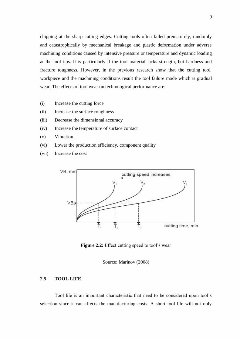
9
chipping at the sharp cutting edges. Cutting tools often failed prematurely, randomly
and catastrophically by mechanical breakage and plastic deformation under adverse
machining conditions caused by intensive pressure or temperature and dynamic loading
at the tool tips. It is particularly if the tool material lacks strength, hot-hardness and
fracture toughness. However, in the previous research show that the cutting tool,
workpiece and the machining conditions result the tool failure mode which is gradual
wear. The effects of tool wear on technological performance are:
(i) Increase the cutting force
(ii) Increase the surface roughness
(iii) Decrease the dimensional accuracy
(iv) Increase the temperature of surface contact
(v) Vibration
(vi) Lower the production efficiency, component quality
(vii) Increase the cost
Figure 2.2: Effect cutting speed to tool’s wear
Source: Marinov (2008)
2.5 TOOL LIFE
Tool life is an important characteristic that need to be considered upon tool’s
selection since it can affects the manufacturing costs. A short tool life will not only
10
require additional tools to be purchased, but will also require time to change the tool
each times it worn out. However, in general, the relationship between the tool’s life and
cutting speed is:
VTn = C (2.1)
where; V= cutting speed in m/min, T= tool life in minutes, C= constant. For high-
speed steel tools the value of C ranges from 0.14 m to 0.1 m and for ceramic tools the
value would be 0.6 m.
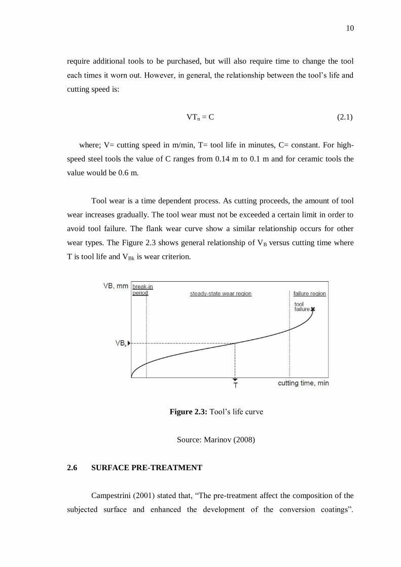
Tool wear is a time dependent process. As cutting proceeds, the amount of tool
wear increases gradually. The tool wear must not be exceeded a certain limit in order to
avoid tool failure. The flank wear curve show a similar relationship occurs for other
wear types. The Figure 2.3 shows general relationship of VB versus cutting time where
T is tool life and VBk is wear criterion.
Figure 2.3: Tool’s life curve
Source: Marinov (2008)
2.6 SURFACE PRE-TREATMENT
Campestrini (2001) stated that, “The pre-treatment affect the composition of the
subjected surface and enhanced the development of the conversion coatings”.

11
According to his work, the pre-treatment provided the rough topography surface which
for adhesion. Surface pre-treatment used to obtain high surface roughness, because the
surface topography plays an important role between coating layer and substrate
interface. The surface topography was examined using scanning electron microscope
(SEM) on several occasions during etching.
2.6.1 Acid Etching
Elsentriecy (2007) stated that, “Chemical or electrochemical pre-treatment
methods, such as acid activation are capable of removing this oxide layer”. The oxide
layer acted as a diffusion barrier that provides poor adhesion. The pre-treatment
methods originated in the need to remove the native oxide layer that does not protect
against corrosion but can easily forms due to the high reactivity of magnesium. Acid
etching pre-treatments included etching the surface to form highly adhering oxides, or
deposited complex inorganic coatings. The pre-treatment provides the best surface for
adhesion.
2.6.2 Hydrofluoric Acid (HF)
According to Berishev (1995), “Studies in acid etching of materials other than
silicon using HF have also reported the effect of HF concentration on the surface
morphology of the etched substrate”. Acid HF is declared as a weak acid because of its
lower dissociation constant compared to the strong acids. Even it was classified as weak
acid, it still highly corrosive acid and capable of dissolving many materials such as
glass. HF was a solution of hydrogen fluoride in water. One of the HF ability was to
dissolve metal oxides is the basis of several applications. In the current work, HF had
been selected as a surface pre-treatment in order to remove the oxide layer on cutting
tool.
Monk and Soane (1993) stated that, “The most widespread method of HF based
etching is the wet etching in a mixture of HF acid and water”. HF behavior benefits in
removing the sacrificial layer in micro-machining. Apart from that, HF can etch glass
through reaction with silicon dioxide and form gaseous or water-soluble silicon
12
fluorides. In this research, HF can act as a cleaning agent of the cutting tool. Acid HF
ionizes in aqueous solution in a similar fashion to other common acids but it does not
fully ionize in dilute aqueous solutions. The chemical reaction is shown in Equation 2.2
and 2.3
HF + H2O H3O+ + F
− (2.2)
HF H+ + FHF
− (2.3)
2.7 COATING
An effective systematic approach was essential for the successful
implementation and sophistication of modem cutting processes. One of the approaches
was by coated improvement. Coating defines as a layer covering that being applied to
the surface of an object or the substrate. Coated cutting tool give many advantages
especially in machining such as improving the mechanical properties of the cutting
tools.
Quinto, et al. (1999) stated that, “The use of Al-containing coating materials is
reported to be advantageous, especially for machining operations which combine high
cutting temperatures with high mechanical stresses on the tool material”. This can be
explained by two effects. Firstly, the formation of a thin alumina layer on tool faces
which come into contact with oxygen protects the coating from tribo-oxidation. This
was important for interrupted cutting operations as well as for reducing notch wear at
the minor cutting edge of coated carbide tools. Secondly, the good wear resistance of
coatings was their comparatively high hardness at elevated temperatures. Figure 2.4
shows the substrate with the coating layer and the overview of coating thickness
structure.

13
Figure 2.4: Coating grain sizes view a) lower thickness, b) higher thickness
Source: Bouzakis (2003)
According to Klocke et al. (1998), “A study including different modern tool
coatings has revealed that coating materials which contain Al provide the best wear
resistance to virtually all wear mechanisms, irrespective of the coating process”. This
was due to their comparatively great hardness, abrasion resistance, oxidation resistance
and to thermal relief of the substrate in the case of volume effects like diffusion and
fatigue. On the other hand, tool coatings used to vary contact conditions by altering
friction, heat generation or heat flow. These are indirect means of influencing wear by
decreasing wear attack. The structure of the tool coating determines both its wear
resistance and the tribological conditions in the contact zones. It was essential to adapt
the coating structure to the demands of a specific machining task. The main influences
on the structure are:
(i) The choice of coating material
(ii) Layer growth during the coating process and
(iii) The structural design of the single layers to form a multi-layer.

14
Furthermore, coated cutting tool also have many advantages in machining which
had been listed as follows:
(i) Improve wear resistance
(ii) Increase tool life
(iii) Improve high hardness
(iv) Improve coefficients of friction
(v) Improve result of adhesion
(vi) Improve wet ability
(vii) Improve corrosion resistance
(viii) Improve scratch resistance
2.8 COATING TECHNIQUE
The morphology of a coating depends mainly on the coating process applied.
The relevant processes for tool’s coating may be differentiated into CVD and PVD
processes. CVD and PVD processes further classified with its effects on coating
structures and on the tribological properties of the coated tools. The process selected
depends on the tool’s material composition and also on the purpose of the tool’s
application. The coated process used to increase mechanical properties of cutting tools
such as high speed steel, cemented carbide, cermets, ceramic, and a super hard material.
Other than that, many cutting tool’s suppliers also combining CVD and PVD processes
in an attempt to gain the advantages of each (Sokovic, 2006).
2.8.1 Physical Vapor Deposition Process (PVD)
This major process used to produce cutting tool’s coatings. It was emerged in the
1980’s as a viable process for applying hard coatings to cemented carbide tools. In PVD
processes, the coating material are evaporated and subsequently condensed on the
cutting tool. The coating is deposited in a vacuum chamber. Further components of the
coating material can be added by using reactive gas. Nitrogen or ammonia gas was
deposited onto the substrate in the chamber. The evaporation process is a main feature
of a specific PVD process.