investigation of seismic response of steel mrf … sause... · steel mrf building structures with...
TRANSCRIPT

Investigation of Seismic Response of Steel MRF Building Structures with
Nonlinear Viscous Dampers Using Real-Time Hybrid Simulation
Richard SauseBaiping Dong
James M. Ricles
Lehigh University
NHERI Lehigh Experimental Facility Researchers Workshop: Advanced Simulation for National Hazards Mitigation
December 5‐6, 2016

Acknowledgements• Sponsors:
– The National Science FoundationThis research was supported by grants from National Science Foundation, Award No. CMS-0936610, in the George E. Brown, Jr. Network for Earthquake Engineering Simulation Research (NEESR) program, and Grant No. CMS-0402490 within the George E. Brown, Jr. Network for Earthquake Engineering Simulation Consortium Operation. Partial support for the development of the test specimen was provided by Award No. CMMI-0830173 in the George E. Brown, Jr. Network for Earthquake Engineering Simulation Research (NEESR) program.
– Pennsylvania Infrastructure Technology Alliance (Pennsylvania Department of Community and Economic Development)
• NEES@Lehigh Staff: Tommy Marullo, Gary Novak• Former Ph.D. students:
– Dr. Yunbyeong Chae, Dr. Cheng Chen, Dr. Oya Mercan
• Nonlinear viscous dampers provided by Taylor Devices, Inc.
2

Overview of Real-time Hybrid Simulation
t t a ei i i i i MX CX r r F
Analytical substructureExperimental substructure
Impose on analytical
substructure
Impose on experimental substructure
Obtain from the experimental
substructure
Obtain from the analytical
substructure by state determination
• In a hybrid simulation, a complete structural system is divided into experimental (physical) and analytical (numerical) substructures
• In a “real-time” hybrid simulation (RTHS), the target displacements are determined and imposed on the substructures in “real time”
~ ~
t t1 1 1Calculate , at ti i i X X
tSolve at i itX
3

Overview of Real-time Hybrid Simulation
• Hybrid simulation is a useful experimental method for investigating seismic response of a complex structural system: ─ Enables part of the system that is poorly understood or difficult to
model to be constructed and tested in the laboratory (i.e., as the experimental substructure) at large-scale under simulated seismic conditions
─ Important remaining parts of the system are represented by one or more numerical model(s) (i.e., analytical substructure(s))
• Hybrid simulations of a structural system with rate dependent components (e.g., dampers) in the experimental substructure should be “real-time” hybrid simulations (i.e., RTHS)
4
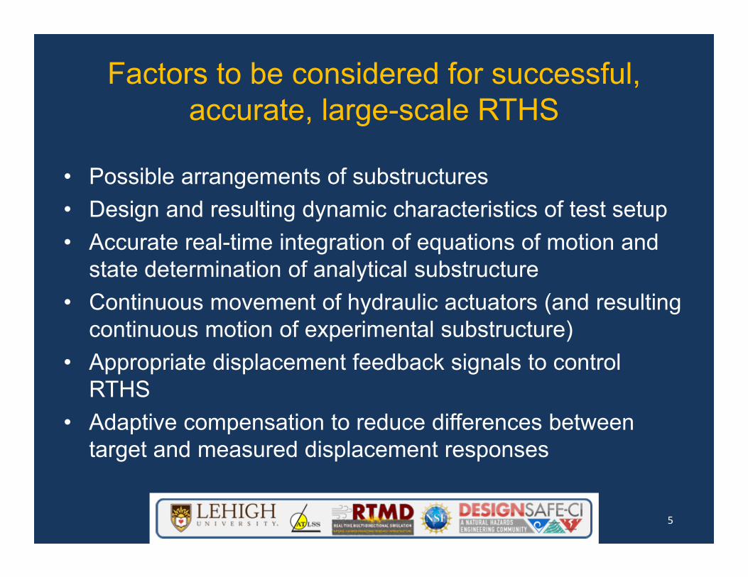
Factors to be considered for successful, accurate, large-scale RTHS
• Possible arrangements of substructures• Design and resulting dynamic characteristics of test setup• Accurate real-time integration of equations of motion and
state determination of analytical substructure• Continuous movement of hydraulic actuators (and resulting
continuous motion of experimental substructure)• Appropriate displacement feedback signals to control
RTHS• Adaptive compensation to reduce differences between
target and measured displacement responses
5

Steel MRF Structure with Nonlinear Viscous Dampers Studied using Large-Scale RTHS
Plan view of prototype building Section view of prototype building
MRF
DBF
6 @25ft
6 @
25ft
6 @25ft
DBF DBF
MRF MRF
3 @
12.5
ft12
.5ft
3 @
12.5
ft
12.5
ft
North
East
NorthSouthSeismic tributary area NorthSouth
North
South
EastWest
Test structure
Prototype building (Dong, Sause, Ricles 2015)— 3-story, 6-bay by 6-bay office building located in Southern California— Moment resisting frame (MRF), damped brace frame (DBF), gravity
load system, inherent damping of building
Dong, B., Sause, R., and Ricles, J.M. Accurate real‐time hybrid earthquake simulations on large‐scale MDOF steel structure with nonlinear viscous dampers. Earthquake Engineering and Structural Dynamics, 2015, 44(12): 2035‐2055 (DOI: 10.1002/eqe.2572)
6

Design of Steel MRF Structure with Nonlinear Viscous Dampers
• Design of prototype building (MRF,DBF) — MRF is designed to satisfy strength
requirement of ASCE 7-10— MRF is not designed to meet drift
requirement of ASCE7-10, story drifts will be controlled by dampers in DBF
— DBF is designed to remain elastic under the design basis earthquake (DBE)
• Maximum story drift of 0.85% and 1.5% was initially estimated for prototype building with three 600 kN dampers (Cα=696 kN-s/m and α=0.44) under DBE and MCE, respectively
Dong, B., Sause, R., and Ricles, J.M. Accurate real‐time hybrid earthquake simulations on large‐scale MDOF steel structure with nonlinear viscous dampers. Earthquake Engineering and Structural Dynamics, 2015, 44(12): 2035‐2055 (DOI: 10.1002/eqe.2572)
7

Nonlinear Viscous Dampers
Damper force versus deformation response from characterization tests conducted using damper test bedRate-dependent response, so hybrid earthquake simulations should be real-time
Large-scale nonlinear viscous damper characterization tests in damper testbed
-60 -40 -20 0 20 40 60-600
-400
-200
0
200
400
600
Damper deformation (mm)
Dam
per f
orce
(kN
)
(a)
f=3.0 Hz
f=4.0 Hz
f=2.0 Hzf=0.5 Hz
f=1.0 Hz
-60 -40 -20 0 20 40 60-600
-400
-200
0
200
400
600
Damper deformation (mm)
Dam
per f
orce
(kN
)
f=0.5 Hzf=1.0 Hz
f=1.5 Hzf=2.0 Hz
(b)
8

Goals for Large-Scale RTHS on Steel MRF Structure with Nonlinear Viscous Dampers
• Experimentally investigate nonlinear viscous damper response within frame structure
• Generate data for evaluating design procedures and numerical models for structures with nonlinear viscous dampers
9

Large-Scale RTHS on Steel MRF Structure with Nonlinear Viscous Dampers: Substructures
Two different arrangements of substructures were used in two phases of RTHS at 0.6 scale RTHS Phase-1
Prototype Building
Experimental substructure:o DBF
Analytical substructure:o MRFo Masso Gravity systemo Building inherent
damping
Experimental substructure:o DBFo MRF
Analytical substructure:o Masso Gravity systemo Building inherent
damping
RTHS Phase-2
MRF
DBF
6 @25ft
6 @
25ft
North
East
Seismic tributary area
Dong, B., Sause, R., and Ricles, J.M. Accurate real‐time hybrid earthquake simulations on large‐scale MDOF steel structure with nonlinear viscous dampers. Earthquake Engineering and Structural Dynamics, 2015, 44(12): 2035‐2055 (DOI: 10.1002/eqe.2572)
10
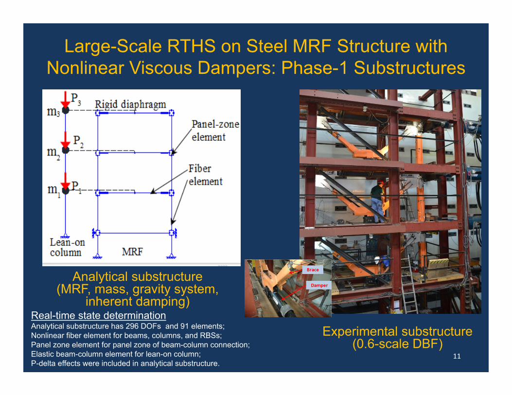
Analytical substructure (MRF, mass, gravity system,
inherent damping)
Experimental substructure (0.6-scale DBF)
Real-time state determinationAnalytical substructure has 296 DOFs and 91 elements;Nonlinear fiber element for beams, columns, and RBSs;Panel zone element for panel zone of beam-column connection;Elastic beam-column element for lean-on column;P-delta effects were included in analytical substructure.
Large-Scale RTHS on Steel MRF Structure with Nonlinear Viscous Dampers: Phase-1 Substructures
11

Experimental substructure (0.6-scale MRF and DBF)
Real-time state determinationAnalytical substructure has 10 DOFs and 3 elements;Elastic beam-column element for lean-on column;P-delta effects were included in analytical substructure.
Large-Scale RTHS on Steel MRF Structure with Nonlinear Viscous Dampers: Phase-2 Substructures
Analytical substructure (mass, gravity system,
inherent damping)
12

Schematic of procedure for RTHS
Within step i
Large-Scale RTHS on Steel MRF Structure with Nonlinear Viscous Dampers: Procedure
13

Integration Algorithm: Integration of equations of motionExplicit CR integration algorithm (Chen, Ricles, Marullo, Mercan 2009)
1 22 1
1 2
, matrices of integration parameters
4 (4 2 )t t
α α
α α M M C K
t1 1
1 12
1 2
Calculate at = 1 :i i
t t ti i it t t ti i i i
t i t
t
t t
X
X X α X
X X X α X
Chen C, Ricles J.M, Marullo T.M, and Mercan O. Real‐time hybrid testing using the unconditionally stable explicit CR integration algorithm. Earthquake Engineering & Structural Dynamics, 2009, 38(1): 23‐44
14
Large-Scale RTHS on Steel MRF Structure with Nonlinear Viscous Dampers: Procedure

Ramp generator: Continuous movement of actuatorsInterpolation of displacements to account for difference in time increment between integration time step (∆t) and controller time interval (δt).
t t, i+1 , 1 i
t,
number of substeps, =4;substep index of the ramp generator, ranges from 1 to ;
and ; target displacement discretized at
target displacements for DOF n at fo
and r th
n i n i
n k
ns nsj nsx txx
tt
the substep within step .j i
t t t t, , 1 , ,( ) ( 1,2, )n k n i n i n i
jx x x x j nsns
15
Large-Scale RTHS on Steel MRF Structure with Nonlinear Viscous Dampers: Procedure

Compensator: Reduce potential errors between target displacement and actual displacment due to dynamic characteristics of servo-hydraulic controller, actuators, test fixture and experimental substructureAdaptive ATS compensator (Chae, Kazemibidokhti, Ricles 2013)
c t t t, 0 , 1 , 2 ,n k k n k k n k k n kx a x a x a x
c th,
t t t th, , ,
0 1 2
compensated command displacement of floor to actuator at = ;
, , target displacement, velocity, and acceleration of floor at ;, , compensator coefficients
n k k t
n k n k n k k
k k k
x n t k
x x x n ta a a
at .kt
Chae Y, Kazemibidokhti K, and Ricles J.M. Adaptive time series compensator for delay compensation of servo‐hydraulic actuator systems for real‐time hybrid simulation. Earthquake Engineering and Structural Dynamics, 2013, 42(11): 1697‐1715
16
Large-Scale RTHS on Steel MRF Structure with Nonlinear Viscous Dampers: Procedure

Use measured displacements from experimental substructure as feedback for RTHS control (Dong, Sause, Ricles 2015)Enables target displacements to be imposed accurately on experimental substructureAccuracy is determined by displacement history of experimental substructure, not by actuator stroke
Dong, B., Sause, R., and Ricles, J.M. Accurate real‐time hybrid earthquake simulations on large‐scale MDOF steel structure with nonlinear viscous dampers. Earthquake Engineering and Structural Dynamics, 2015, 44(12): 2035‐2055 (DOI: 10.1002/eqe.2572)
17
Large-Scale RTHS on Steel MRF Structure with Nonlinear Viscous Dampers: Procedure

Large-Scale RTHS on Steel MRF Structure with Nonlinear Viscous Dampers
18
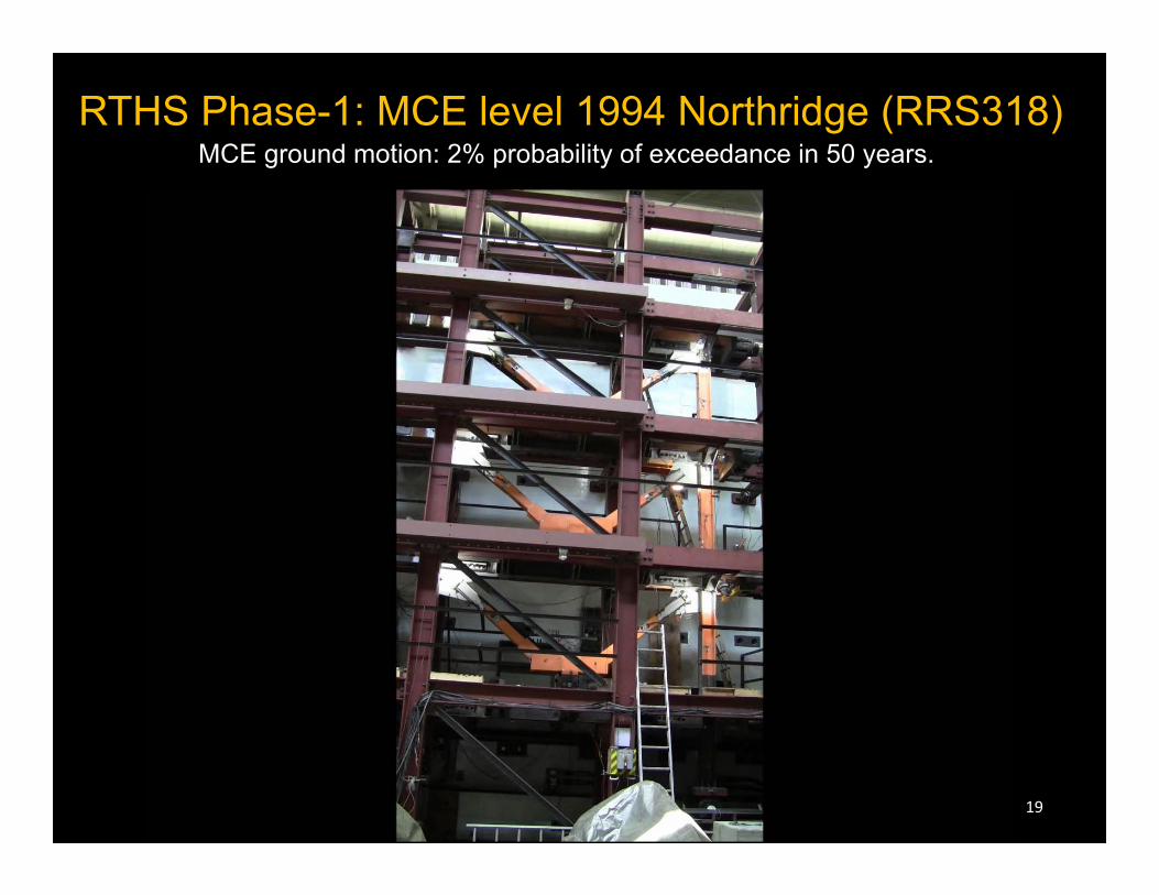
RTHS Phase-1: MCE level 1994 Northridge (RRS318)MCE ground motion: 2% probability of exceedance in 50 years.
19

RTHS Phase-1 Results EvaluationFloor Displacements in MCE level 1994 Northridge (RRS318)
Peak floor displacement:31.1, 63.7, 85.5 mmMaximum amplitude error: 1.1, 1.6, 2.0 mm(3.5%, 2.5%, 2.3%)Delay: about 2.0 ms
Dong, B., Sause, R., and Ricles, J.M. Accurate real‐time hybrid earthquake simulations on large‐scale MDOF steel structure with nonlinear viscous dampers. Earthquake Engineering and Structural Dynamics, 2015, 44(12): 2035‐2055 (DOI: 10.1002/eqe.2572).
20

RTHS Phase-1 Results EvaluationError between xm and xt in MCE level 1994 Northridge (RRS318)
Dong, B., Sause, R., and Ricles, J.M. Accurate real‐time hybrid earthquake simulations on large‐scale MDOF steel structure with nonlinear viscous dampers. Earthquake Engineering and Structural Dynamics, 2015, 44(12): 2035‐2055 (DOI: 10.1002/eqe.2572).
21

Comparison of xc, xa, xm and xt in MCE level 1994 Northridge (RRS318)
22
RTHS Phase-1 Results Evaluation
Dong, B., Sause, R., and Ricles, J.M. Accurate real‐time hybrid earthquake simulations on large‐scale MDOF steel structure with nonlinear viscous dampers. Earthquake Engineering and Structural Dynamics, 2015, 44(12): 2035‐2055 (DOI: 10.1002/eqe.2572).

2 4 6 8 10 12 14 16-0.6
0
0.6
3rd
floor
_xt _xm
2 4 6 8 10 12 14 16-0.6
0
0.6
Floo
r vel
ocity
(m/s
) 2n
d flo
or
_xt _xm
0 2 4 6 8 10 12 14 16 18-0.6
0
0.6
Time (s)
1st f
loor
_xt _xm
(a)2.5 2.75 3 3.25 3.5
-0.6
-0.4
-0.2
0
0.2
0.4
0.6
Time (s)
Floo
r vel
ocity
(m/s
)
_xt
_xm
1st floor
3rd floor2nd floor
(b)
Peak velocity: 0.198, 0.422, 0.531 m/sMaximum difference: 0.005, 0.007, 0.009m/s (2.5%, 1.7%, 1.7%)
RTHS Phase-1 Results EvaluationFloor Velocities in MCE level 1994 Northridge (RRS318)
Dong, B., Sause, R., and Ricles, J.M. Accurate real‐time hybrid earthquake simulations on large‐scale MDOF steel structure with nonlinear viscous dampers. Earthquake Engineering and Structural Dynamics, 2015, 44(12): 2035‐2055 (DOI: 10.1002/eqe.2572).
23

RTHS Phase-2: MCE level 1994 Northridge (RRS318)MCE ground motion: 2% probability of exceedance in 50 years.
24

Peak floor displacement:33.3, 65.4, 83.7 mmMaximum amplitude error: 1.2, 0.9, 1.9 mm(3.6%, 1.4%, 2.3%)Delay: about 2.0 ms
RTHS Phase-2 Results EvaluationFloor Displacements in MCE level 1994 Northridge (RRS318)
Dong, B., Sause, R., and Ricles, J.M. Accurate real‐time hybrid earthquake simulations on large‐scale MDOF steel structure with nonlinear viscous dampers. Earthquake Engineering and Structural Dynamics, 2015, 44(12): 2035‐2055 (DOI: 10.1002/eqe.2572).
25

Comparison of RTHS Phase-1 and Phase-2 Results
Comparison of floor displacements in Phase-1 and Phase-2 MCE level 1994 Northridge (RRS318)
Peak displacement (Phase‐1):31.1, 63.7, 85.5 mmMaximum difference: 2.1, 1.7, 1.8 mm(6.8%, 2.7%, 2.1%)
Dong, B., Sause, R., and Ricles, J.M. Accurate real‐time hybrid earthquake simulations on large‐scale MDOF steel structure with nonlinear viscous dampers. Earthquake Engineering and Structural Dynamics, 2015, 44(12): 2035‐2055 (DOI: 10.1002/eqe.2572).
26

Parametric study of Prototype Buildings with reduced-strength steel MRF designs in Phase-1 RTHS (Dong, Sause, Ricles 2016)
– D100V: with MRF designed for 100% of base shear design demand– D75V: with MRF designed for 75% of base shear design demand– D60V: with MRF designed for 60% of base shear design demand
(a) Seismic tributary area for D100V prototype building
(b) Seismic tributary area for D75V prototype building
(c) Seismic tributary area for D60V prototype building
Use of RTHS in Earthquake Engineering Research
Change mass and gravity system properties of analytical substructure to perform RTHS for three different Prototype Buildings
Dong, B., Sause, R., and Ricles, J.M., Seismic Response and Performance of Steel MRF Building with Nonlinear Viscous Dampers under DBE and MCE, Journal of Structural Engineering, 2016, 142(6): 04016023‐1 – 04016023‐16 (DOI: 10.1061/(ASCE)ST.1943‐541X.0001482)
27

Phase-1 experimental substructure (DBF with dampers) is undamaged by DBE and MCE input
Damage is confined to MRF within analytical substructure in Phase-1
Therefore, an ensemble of ground motion records can be used as input for Phase-1 RTHS (account for record-to-record variability
0 0.5 1 1.5 2 2.5 30
0.5
1
1.5
2
2.5
Period, Tn (s)
Spe
ctra
l acc
eler
atio
n, S
a (g
)
DBE-1DBE-2DBE-3DBE-4DBE-5DBE-6DBE-7Median spectrumTarget hazard spectrum
(a)
0 0.5 1 1.5 2 2.5 30
0.5
1
1.5
2
2.5
Period, Tn (s)
Spe
ctra
l acc
eler
atio
n, S
a (g
)
MCE-1MCE-2MCE-3MCE-4MCE-5MCE-6MCE-7Median spectrumTarget hazard spectrum
(b)
Ground motion response spectra (a) DBE level; (b) MCE level
Use of RTHS in Earthquake Engineering Research
28Dong, B., Sause, R., and Ricles, J.M., Seismic Response and Performance of Steel MRF Building with Nonlinear Viscous Dampers under DBE and MCE, Journal of Structural Engineering, 2016, 142(6): 04016023‐1 – 04016023‐16 (DOI: 10.1061/(ASCE)ST.1943‐541X.0001482)

Use of RTHS in Earthquake Engineering Research: Statistical Evaluation of Response from RTHS
DBE level RTHS:• Mean maximum story drifts:
0.71%, 0.78%, and 0.54% for the 1st, 2nd, and 3rd story
• Negligible residual story drift
Ground Motion No. Story drift (%) Residual story drift (%)1st story 2nd story 3rd story 1st story 2nd story 3rd story
DBE‐1 0.68 0.82 0.53 0.009 0.013 0.022DBE‐2 0.63 0.73 0.52 0.000 0.000 0.000DBE‐3 0.68 0.76 0.48 0.013 0.017 0.009DBE‐4 0.79 0.82 0.55 0.031 0.035 0.022DBE‐5 0.62 0.71 0.49 0.004 0.004 0.009DBE‐6 0.79 0.80 0.55 0.044 0.044 0.022DBE‐7 0.71 0.80 0.57 0.013 0.013 0.000
DBE Mean 0.71 0.78 0.54 0.016 0.018 0.012DBE prediction 0.76 0.81 0.64 ‐ ‐ ‐
Ground Motion No. Story drift (%) Residual story drift (%)1st story 2nd story 3rd story 1st story 2nd story 3rd story
MCE‐1 1.25 1.48 1.09 0.118 0.176 0.137MCE‐2 1.10 1.29 0.88 0.042 0.061 0.035MCE‐3 1.18 1.34 1.03 0.042 0.085 0.076MCE‐4 1.09 1.35 1.02 0.087 0.159 0.131MCE‐5 1.27 1.39 0.98 0.091 0.124 0.060MCE‐6 1.07 1.24 0.91 0.112 0.150 0.104MCE‐7 1.32 1.44 1.00 0.080 0.105 0.079
MCE Mean 1.18 1.37 0.99 0.082 0.123 0.089MCE prediction 1.33 1.41 1.12 ‐ ‐ ‐
MCE level RTHS:• Mean maximum story drifts:
1.18%, 1.37%, and 0.99% for the 1st, 2nd, and 3rd story
• Mean residual story drift : 0.08%, 0.12%, and 0.09% for the 1st, 2nd, and 3rd story
Predicted drift is close to mean from RTHS
29
D100V structure

Use of RTHS in Earthquake Engineering Research: Statistical Evaluation of Response from RTHS
DBE level RTHS:• Mean maximum story drifts:
0.71%, 0.78%, and 0.54% for the 1st, 2nd, and 3rd story
• Negligible residual story drift
Ground Motion No. Story drift (%) Residual story drift (%)1st story 2nd story 3rd story 1st story 2nd story 3rd story
DBE‐1 0.68 0.82 0.53 0.009 0.013 0.022DBE‐2 0.63 0.73 0.52 0.000 0.000 0.000DBE‐3 0.68 0.76 0.48 0.013 0.017 0.009DBE‐4 0.79 0.82 0.55 0.031 0.035 0.022DBE‐5 0.62 0.71 0.49 0.004 0.004 0.009DBE‐6 0.79 0.80 0.55 0.044 0.044 0.022DBE‐7 0.71 0.80 0.57 0.013 0.013 0.000
DBE Mean 0.71 0.78 0.54 0.016 0.018 0.012DBE prediction 0.76 0.81 0.64 ‐ ‐ ‐
Ground Motion No. Story drift (%) Residual story drift (%)1st story 2nd story 3rd story 1st story 2nd story 3rd story
MCE‐1 1.25 1.48 1.09 0.118 0.176 0.137MCE‐2 1.10 1.29 0.88 0.042 0.061 0.035MCE‐3 1.18 1.34 1.03 0.042 0.085 0.076MCE‐4 1.09 1.35 1.02 0.087 0.159 0.131MCE‐5 1.27 1.39 0.98 0.091 0.124 0.060MCE‐6 1.07 1.24 0.91 0.112 0.150 0.104MCE‐7 1.32 1.44 1.00 0.080 0.105 0.079
MCE Mean 1.18 1.37 0.99 0.082 0.123 0.089MCE prediction 1.33 1.41 1.12 ‐ ‐ ‐
MCE level RTHS:• Mean maximum story drifts:
1.18%, 1.37%, and 0.99% for the 1st, 2nd, and 3rd story
• Mean residual story drift : 0.08%, 0.12%, and 0.09% for the 1st, 2nd, and 3rd story
30
Predicted drift is close to mean from RTHS D100V structure

DBF flexibility produces differences between damper deformation and story driftDamper forces are more in-phase with DBF column shear forces
Damper force and DBF column shear versus story drift
Damper force-damper deformation and damper force-story drift
D100V structureMCE RRS318
Use of RTHS in Earthquake Engineering Research: Steel MRF Structure with Viscous Dampers: Results
31

Damper forces are partly in-phase with MRF story shear (at peak MRF story shear, damper force is large)DBF forces large at time of peak MRF forces
MRF story shear and damper force versus story drift
MRF and DBF story shear versus story drift
D100V structureMCE RRS318
32
Use of RTHS in Earthquake Engineering Research: Steel MRF Structure with Viscous Dampers: Results
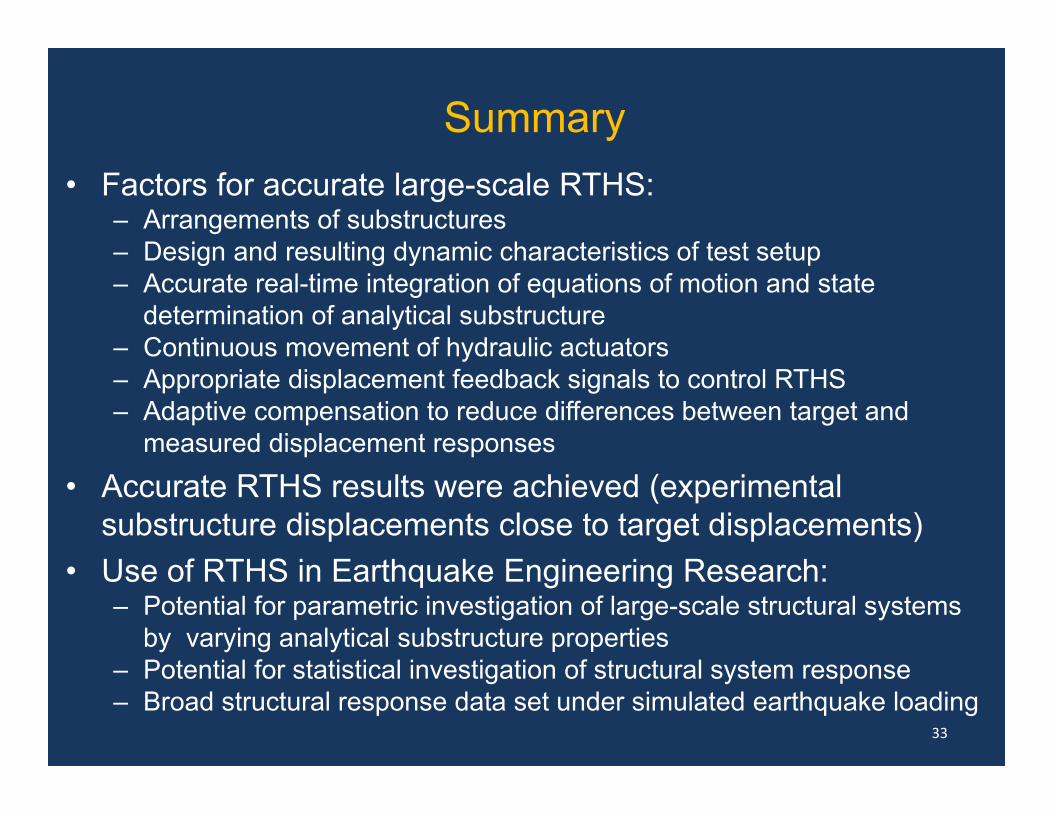
Summary• Factors for accurate large-scale RTHS:
– Arrangements of substructures– Design and resulting dynamic characteristics of test setup– Accurate real-time integration of equations of motion and state
determination of analytical substructure– Continuous movement of hydraulic actuators– Appropriate displacement feedback signals to control RTHS– Adaptive compensation to reduce differences between target and
measured displacement responses
• Accurate RTHS results were achieved (experimental substructure displacements close to target displacements)
• Use of RTHS in Earthquake Engineering Research: – Potential for parametric investigation of large-scale structural systems
by varying analytical substructure properties– Potential for statistical investigation of structural system response– Broad structural response data set under simulated earthquake loading
33

Selected References• Shing P.B, Mahin S.A. Computational aspects of a seismic performance test method using on‐
line computer control. Earthquake Engineering and Structural Dynamics, 1985, 13(4): 507‐526.• Thewalt C.R, Mahin S.A. Hybrid solution techniques for generalized pseudodynamic testing.
Report No. UCB/EERC‐87/09, Earthquake Engineering Research Center, University of California, Berkeley, 1987.
• Nakashima M. Integration techniques for substructure pseudo‐dynamic test. 4th US National Conference on Earthquake Engineering, 1990.
• Chen C, Ricles J.M, Marullo T.M, and Mercan O. Real‐time hybrid testing using the unconditionally stable explicit CR integration algorithm. Earthquake Engineering & Structural Dynamics, 2009, 38(1): 23‐44.
• Chae Y, Kazemibidokhti K, and Ricles J.M. Adaptive time series compensator for delay compensation of servo‐hydraulic actuator systems for real‐time hybrid simulation. Earthquake Engineering and Structural Dynamics, 2013, 42(11):1 697‐1715.
• Dong, B., Sause, R., and Ricles, J.M. Accurate real‐time hybrid earthquake simulations on large‐scale MDOF steel structure with nonlinear viscous dampers. Earthquake Engineering and Structural Dynamics, 2015, 44(12): 2035‐2055 (DOI: 10.1002/eqe.2572).
• Dong, B., Sause, R., and Ricles, J.M., Seismic Response and Performance of Steel MRF Building with Nonlinear Viscous Dampers under DBE and MCE. Journal of Structural Engineering, 2016, 142(6): 04016023‐1 – 04016023‐16 (DOI: 10.1061/(ASCE)ST.1943‐541X.0001482).
34

35
Investigation of Seismic Response of Steel MRF Building Structures with
Nonlinear Viscous Dampers Using Real-Time Hybrid Simulation
NHERI Lehigh Experimental Facility Researchers Workshop: Advanced Simulation for National Hazards Mitigation
December 5‐6, 2016
Thank you