investigation of plasma polymerization
TRANSCRIPT

DEVELOPMENT OF NOVEL POTENTIAL OF
PLASMA POLYMERIZATION TECHNIQUES
FOR SURFACE MODIFICATION
TOTA PIRDO KASIH
A dissertation submitted to
Graduate School of Engineering Gunma University
for The Degree of
Doctor of Engineering
February, 2007

DEVELOPMENT OF NOVEL POTENTIAL OF PLASMA
POLYMERIZATION TECHNIQUES FOR SURFACE MODIFICATION
CONTENTS
1. Chapter I 1
General Introduction
2. Chapter II 19
Development and Characterization of a Novel
Non-equilibrium Atmospheric Pressure Plasma Torch
3. Chapter III 38
Poly(methyl methacrylate) Films Deposited via
Non-equilibrium Atmospheric Pressure Plasma Polymerization
with Using Argon as the Working Gas
4. Chapter IV 57
Non-equilibrium Atmospheric Pressure Argon Plasma Torch
For Deposition of Thin Silicon Oxide Film
5. Chapter V 82
Surface Modification of Kenaf Fiber via Plasma-induced
Graft Polymerization
6. Chapter VI 103
Summary
List of Achievements 106
Acknowledgement 108

Referee in-Chief : Professor H. Kubota
Referees : Professor M. Unno
Professor R. Katakai
Professor S. Tobita
Professor T. Komoto

ABSTRACT
Plasma polymerization technique includes plasma(-state) polymerization and
plasma-induced graft polymerization and it is one of the most powerful method for
surface modification of polymeric materials. Base on the unsolved problems that still
exist on the usage of plasma polymerization in industrial application, the works
described in this thesis are intended to explore the application of the plasma discharge
either for deposition of thin solid films using a newly developed non-equilibrium
atmospheric pressure plasma torch as well as for inducing graft polymerization on
plant fibers under low pressure condition.
The major part of the thesis is directed toward the development of a novel
non-equilibrium atmospheric pressure plasma torch with its name: CAPPLAT (Cold
Atmosphere Pressure Plasma Torch) and exploring the use of it for depositing plasma
polymerized films having organic and inorganic features. The torch consists of a 4
mm inner diameter metal pipe (inner electrode) surrounded by a silicone tube
(dielectric) and a metal belt of 20 mm wide (outer electrode) is placed around the
silicone tube at its end. The temperature of the generated plasma jet is as low as room
temperature. When the rare gas was used to generate the discharge, electrical
diagnostic exhibited the homogeneous glow type discharge. Optical emission
spectroscopy confirmed the inclusion of air component to the plasma jet. By selecting
the applied voltage and gas flow rate, a proper condition for sufficient plasma jet
length could be adjusted.
Applications of the torch have been realized to deposit both of organic and
inorganic thin films. The organic film of plasma polymerized methyl methacrylate

(PPMMA) obtained by using argon (Ar) plasma torch has been found to be
chemically and spectroscopically similar to that of conventional PMMA. This could
be happened when the rate of MMA-carrying Ar gas was high enough to change the
filamentary character of Ar plasma to the glow-like one. For the deposition of thin
film from hexamethyldisiloxne (HMDSO) monomer with the inorganic character, it
was found that the plasma generated by using Ar as the working gas was more
effective than helium (He) plasma in terms of both quality and deposition rate of film
at the same applied power, frequency and gas composition. This could be realized by
adjusting the oxygen feed through the HMDSO bubbler. Moreover, the appearance of
the film could be improved when a small amount nitrogen (N2) was admixed to the Ar
as a feed gas. The Ar/N2 mixed gas by the composition of 30/1 was found to result in
homogeneous appearance of discharge and could deposit the SiO2-like film with
better quality at the similar growth rate to the deposition by pure Ar plasma.
Plasma-induced graft polymerization of methyl methacrylate (MMA) onto
kenaf fiber was studied with using a low pressure non-equilibrium plasma. The graft
polymerization onto plant fiber with high content of lignin was successfully achieved
by introducing peroxides on the fiber through plasma treatment. Vinyl monomer was
chosen in order to change the hydrophylic surface of kenaf onto hydrophobic one
without sacrifying its potential bulk properties. The chemical structure and
morphology of the grafted surface fiber have been characterized by FT-IR, XPS and
SEM analyses. Those characterizations indicated that the kenaf fiber was partially
coated by PMMA. Nevertheless, judging from the results of TG/DTG study, the graft
polymerized kenaf fiber has higher thermal stability than untreated one.

CHAPTER I
GENERAL INTRODUCTION
1.1. Plasma and State of The Art
Plasma is physically defined as an ionized gas in a neutral state with an equal
number of positively and negatively charged particles (quasi-neutral). It consists of
free electrons, radicals, ions, UV-radiation, and various highly excited neutral and
charged species independent of the gases used. The entire plasma is electrically
neutral, but its behavior is complex because the particles motions are controlled by
electric and magnetic fields. In 1879 Sir William Crookes firstly defined this state of
ionized gas as `the fourth state of matter` after solid, liquid and gas. The term of
`plasma` itself has been introduced by Irving Langmuir[1] when he studied the
electrified gases in vacuum tubes in 1928. Gases usually become ionized only when
heated to very high temperatures (>5000oC), so plasma is usually a very hot substance.
However, if the degree of gas ionization is very weak, low temperature plasma can
also be generated, which is usually realized by electrical discharge.[2] Well known
examples of plasmas are the sun and other stars in the universe which have
temperatures ranging from 5000 to 70000oK and consist entirely of plasma.[3]
Lightning, an electric discharge in air, can be considered as a plasma as well. These
are the examples of natural and human-uncontrolled plasma. Man-made controlled
1

plasmas can be generated usually by electric device and have been used in industry
for many years for a number of diverse applications. Fluorescent lamps, neon tubes
and gas lasers are the actualization of man-made plasma devices.
According to the gas temperature, plasma can be classified into two types:
thermal or equilibrium plasma which is fully ionized (gas temperature, Tg ≈ electron
temperature, Te) and cold (low temperature) or non-equilibrium plasma with the gas
only partially ionized (Tg « Te). Thermal plasma implies that the temperature of all
active species (electron, ion and neutral) is the same. In practical application, it is
typically used where heat is required, such as for cutting, welding, spraying or
evaporation of analyte material in analytical ICP.[4] Cold plasma on the other hand
plays an essential role in many fields of plasma processing in which the heat is not
desirable such as for etching and deposition. The temperature of neutral and positively
charged species is low, while the electrons are relatively in much higher temperature
because they are light and easily accelerated by the applied electromagnetic fields. As
a result the generated plasma is in the state of non-equilibrium and the reaction may
proceed at low temperature, possibly to as low as room temperature. Consequently,
cold plasma is well suited for the treatment or surface modification of
temperature-sensitive materials.
There are various ways to supply necessary energy for plasma generation such
as laser beams, flames and adiabatic compression. However, application of electric
field is by far the most common method for plasma ignition. Direct current (DC)
discharges, pulsed DC discharges, radio frequency (RF) discharges (13.56 MHz) and
2
microwave discharges (2.45 GHz) are the plasmas categorization based on electric
apparatus. These common standard frequencies were chosen in order not to make
interfering with telecommunication.[5] In technical applications, low temperature
plasmas may be produced by those types of electrical sources. The basic feature of a
variety of electrical discharges is that they produce plasmas in which the majority of
the electrical energy primarily goes into production of energetic electrons, instead of
heating the entire gas stream.[6] These energetic electrons induce ionization, excitation
and molecular fragmentation process of the background gas molecules to produce
excited species, free radicals and ions as well as additional electrons, leading to a
complex mixture of active species which environmentally `chemically-rich`. Due to
its essential role, the electrons are therefore considered to be the `primary agents` in
the plasma.
1.2. Low Temperature Plasma Parameters
Plasma is broadly characterized by the following basic parameters: plasma
density, degree of ionization and electron energy distribution. Plasma density refers to
the particle number densities of electrons, ne, and is approximately equal to the
density of the ions, ni, by the assumption of plasma quasi-neutrality. One of the most
important plasma types for technical application is `glow discharge`, and the
mechanism of the gas discharge can be explained by the following idea. In between of
two electrodes placed in a gas a few electrons are emitted due to the omnipresent
cosmic radiation. When a sufficiently high potential difference is applied to the
3

electrodes, the electrons are accelerated by the electric field and promoting ionization
and other activation processes through the collision reactions with the gas atoms.
When the electric field strength is high enough and some requirements such as
pressure, gas nature and reactor design are fulfilled, this leads to electrical breakdown
of the gas, which results in a self-sustaining discharge. The most important collisions
are the inelastic collisions, leading to excitation and ionization. The excitation
collisions followed by light emission of de-excitation are responsible for the glow
characteristic of the discharge, while the ionization collisions create new electrons and
ions and lead to the increasing of ionization degree to about 10-6-10-3. The steady state
of glow discharge is obtained when the charge loss due to gas phase or surface
recombination is compensated by new ionizations. Due to the strongly influence of
electrons to the plasma properties, it is important to characterize the plasma by its
electron energy distribution function (EEDF). This parameter can be used to
determine the electron temperature (Te) which distincts a variety types of plasmas.
The shape of the EEDF depends on the energy lost via electron collisions and the
energy gained by the time-dependent electric field in the plasma. Maxwell and
Druyvesteyn distribution are the better approximation of the electron energy
distribution for the low pressure plasma where the temperature of electrons is
considered much higher than that of the ions, and when it assumed that the only
energy loses are by elastic collisions. Figure 1.1 shows their distribution function for
different average electron energies. For low-pressure plasmas containing mainly inert
gases the electrons distribution can be characterized by a Maxwellian EEDF, although
4

the
Figure 1.1 Electron energy distribution according to Maxwell and
Druyvesteyn for three different average electron energies.[8]
5

the deviations have been reported.[7] However, most of discharges are not
characterized by Maxwell distribution, particularly when using admixed gases or
gaseous monomer. Both energy distributions show that the bulk of the electrons
belong to the low-energy electrons (0.5–5 eV) while a small number of electrons have
relatively high energies (5–14 eV). This high-energy tail region, however, plays an
important role for dissociation and ionization reactions since those reactions have an
energetic threshold and only happen if the energy of the participating electrons is
higher.
Electrons determine the plasma characteristics as they are responsible for elastic
and inelastic collisions. In elastic collisions the internal energy of the neutrals are
unchanged, whereas the energy, momentum, and direction of the electrons undergo
large changes. In inelastic collisions the energy that is transferred from the electron to
the neutral species, causes many processes to occur, such as dissociation,
(dissociative) ionization, (dissociative) attachment, recombination and dissociative
excitation. Each of these processes is characterized by its own cross-section, σ(Ε)
which is showed overlapping with EEDF in Figure 1.2. The rate constant k of the
electronically collisional processes is proportional to the product of EEDF and
cross-section, according to the following formula:
k = ʃ E1/2 f(E)σ(E) dE
The onset of these processes starts at 10 eV or higher, while the EEDF peaks around
1-2 eV. Hence, the tail of the EEDF mainly determines which processes can possibly
occur.
6

E diss E ion
f (E)
σ(E)
E
proportional to the product of the two.[9]
cross-section. The rate of an electronic reaction is
Figure 1.2 Electron energy distribution function and the reactive
7

1.3. Plasma Polymerization
Starting in the 1960s, scientists have successfully explored the plasma
techniques in material science, including plasma polymerization.[10,11] Inspired to the
use of plasma polymer as a dielectric film during the early development of
microelectronic field at that time, the systematic investigations of plasma
polymerization were followed by the rapid advancement of polymer science.
Nowadays, the advantages of plasma polymerization have been fully recognized not
only in the field of microelectronics but also covering many potential applications in
optical field, polymer science, sensors, membrane and surface modification of
biomedical materials.[12]
Most of the works corresponding to the plasma polymerization, however, were
intended for surface modifications of polymer surface. This is due to the fact that the
effects of the plasma do not penetrate more than 100 Å from the surface.[13] Because
the bulk of the material is not affected by the treatment, the desirable structural
characteristics can be maintained. Polymerization under influence of plasma can be
divided into two methods: plasma-state polymerization and plasma-induced graft
polymerization. In the last two decades, both of these processes have been utilized to
develop macromolecular plasma chemistry, with emphasizing directions to the surface
functionalization of polymeric materials and plasma-enhanced synthesis of thin layer
of macromolecular structures.[14]
1.3.1. Plasma(-State) Polymerization
Plasma-state polymerization, which is simply so-called by plasma
8

polymerization, deals with the formation of deposit thin films from gaseous
atmosphere containing monomer with the aid of plasma. Plasma enhanced chemical
vapor deposition (PECVD) is the synonymous name of this method. The term plasma
polymerization is used to emphasize deposition process from organic-based
monomers while PECVD is used for depositing films with rather inorganic character.
The principle process of plasma polymerization can be explained by the following
concept. Upon transfer energy in the plasma through inelastic collisions, the
monomers are fragmented into activated species, free radicals and/or their constituent
atoms. The activated fragments are recombined and re-arranged by a rapid step
growth mechanism, and deposition occurs due to a loss of kinetic energy upon
collision of the activated species with the substrates or walls of the reactor. The loss
of kinetic energy is due either to a chemical reaction of the species or increased
molecular weight.[15] The activated species for film formation come from the gas
phase, but the actual film formation proceeds at the substrate surface. Deposited
species containing unpaired electrons are highly unstable, and the molecules become
highly reactive at the surface of exposed substrates. The repetition of
activation/fragmentation and recombination leads to film formation. The advantages
of plasma polymerization include the fact that highly cross-linked, pinhole free,
thermally and chemically stable, very adherent and conformal thin films can be
deposited on most substrates, using a relatively simple one-step coating
procedure.[16,17] Furthermore, plasma polymerized films can also be prepared from
monomers that cannot be polymerized by conventional chemical techniques such as
methane, saturated hydrocarbons and organo-metallics. The structure of deposited
9

films is not as well defined as that of conventional polymers and still remains as a
very complex process that is not quite well understood. However, several groups have
reported that the characteristics of plasma-formed films are highly influenced by
many different factors such as reactor geometry, input power, frequency, substrate
temperature and monomer flow rate.[18-24]
1.3.2. Plasma-Induced Graft Polymerization
In the plasma-induced graft polymerization which is often referred to plasma
grafting, activation of substrate surface is initiated by plasma under reactive gas
atmosphere followed with the subsequent grafting reaction of vinyl monomers, either
in the presence of vapor or liquid phase.[25,26] The effects of plasma treatment on the
substrate surface allows determination of maximum concentration of the formed free
radicals, while the degree of grafting itself is influenced by grafting parameters such
as: monomer concentration, grafting time and graft medium. The following two
different mechanisms have been generally used to explain the occurrence in plasma
grafting:[27]
(1) The creation of active species on the polymer surface, followed by contact with
the monomer:
In this mechanism, free radicals are formed on the polymer surface as a result of inert
gas plasma treatment. These radicals can either directly initiate grafting or be
10

converted into peroxide or hydroperoxides by the inclusion of an oxidative gas. These
activated peroxides will also initiate grafting in the presence of the monomer
species.[28] This method, however, has a potential limitation by side reactions during
transport from the reactor into the contacted monomer, which lower the yield.[29]
(2) Direct grafting of the polymer with common or unconventional monomers
under “monomer”-plasma conditions:
Unlike the previous method, this involves a combined plasma and monomer exposure
directly in one step by the use of gaseous monomers in the working gas mixture. The
lack of this method is the restriction of monomers with a sufficiently high vapor
pressure.[19] However, both of these techniques have shown great advantages over
conventional grafting by offering a large range of chemical compounds to be used as
monomers, varying thickness of monomer layers, and limited destruction of bulk
properties.[18] In this thesis, low pressure cold plasma under air atmosphere was
utilized to introduce reactive species on kenaf fiber. These free radicals were allowed
to convert to the peroxide after reaction with oxidative air prior to successive graft
polymerization.
1.4 Problems in Plasma Polymerization Technique
Non-equilibrium low temperature plasma for plasma polymerization can be
11

achieved in a wide range of temperatures and pressures. To date, the well established
method in low temperature plasma processing is carried out by transferring electrical
energy in between two electrodes under reduced pressure in the range of 10 to 1000
Pa. The so-called low-pressure plasma has been come to a great value in fundamental
research as well as plasma technology. However, this technique lacks in some points
such as the necessity of the vacuum system which leads to the costly operation and the
batch processes that are unsuitable for the continuous sequence of manufacturing
because the samples needed to be transferred into and out of a vacuum system.
Therefore, in order to overcome such problems, recent trends have been focusing on
the development of new plasma sources operated at atmospheric pressure with still
keeping the characteristic of low temperature.[30] Several numbers of atmospheric
pressure plasma sources have been developed for generating non-equilibrium plasma
such as conventional dielectric barrier discharge (DBD),[31-33] planar DBD,[34] various
types of coronas,[35,36] micro-hollow cathode,[37] direct current,[38] microwave (MW)
discharge,[39] and radio frequency glow discharges.[40-43] Some of them have been
proved to be utilized for PECVD to effectively deposit thin solid films with
characteristics comparable to those films deposited using low pressure modes.[44-46]
Major part of this thesis deals with the study in developing a novel atmospheric
pressure plasma torch and its application on depositing thin solid films that having
characteristic of either organic and inorganic (silicon dioxide) features. The
advantages of using this novel torch not only can be operated in atmospheric pressure,
thus, solving two shortcomings mentioned above and satisfying the reduced cost
requirements, but also can be employed without needing a chamber, hence, capable to
12
carry out plasma treatment of even complex geometry substrate with no limitation in
size.
Low pressure plasma treatment, however, still be engaged in academic or
industrial application of plasma. This is due to the specific property of low pressure
plasma system to easily generate glow discharge in spite of the type of gases used.
Moreover, treatment with the glow discharge results in better properties on substrate
surface than filamentary discharge due to the homogeneous character of the discharge.
From these points of view low pressure plasma keeps its function in many fields of
plasma applications. The low pressure plasma technology has more than 40 years
history and has been used in a variety of applications, however, there still exists
unsolved problems. Limiting the applications to the polymer treatment, one of the
problems should be ascribed to the matter of substrates. If the plasma would be
conducted with the purpose only for surface treatment, any kinds of polymer
substrates can be processed. However, for the purpose of modification by graft
polymerization, the substrate to modify has been mostly in the form of film or
textile[47-49] and little attempt have been reported for fibers. Above all fibers, natural
fiber, especially plant fiber has not been the substrate for plasma-induced grafting.
This is mainly because natural fibers are complex substrates with relatively high
lignin content, thus very difficult to proceed the grafting. However, due to its
potentially outstanding properties as the filler for environment conscience composite
materials, the increase in the use of natural fiber is very rapid.
In this thesis, low pressure plasma has been applied to induce graft
polymerization of methyl methacrylate onto natural kenaf fiber. This research was
13

executed with the purpose of modification the hydrophilic surface of kenaf closer to
hydrophobic surface in order to increase the compatibility with the polymer matrix for
preparation composite material where the treatment did not alternate the high ratio
properties of kenaf fiber. Combination of the plasma surface activation with
post-plasma grafting using aqueous solutions is chosen as an environmentally
attractive alternative to the use of organic solvents. This technique avoids organic
solvents for the graft polymerization, thereby reducing the environmental pollution
caused by the production process of highly toxic wastes.
1.5. Aims of This Thesis
The main objective of this works is developing a novel non-equilibrium
atmospheric pressure plasma source operated based on argon gas and explores the
possibility of using this tool in depositing organic-based thin film and silica-like films.
Polymer thin films are great of interest for surface engineering of organic and
inorganic substrate surfaces to enhance the substrate’s chemical selectivity and
modify the surface topology in such areas as chemical sensing, barrier coatings,
biotechnology and separation technology. The approach consists in analyzing the gas
phase chemistry as well as characterization of deposit films in order to be able to form
the relationship between the discharge parameters and deposition properties. This can
be fulfilled by performing in situ diagnostic with optical emission spectroscopy (OES),
and film characterization with Fourier transform spectroscopy (FTIR), X-ray
photoelectron spectroscopy (XPS) and scanning electron microscope (SEM).
The second objective of this thesis is to try the application of low pressure
14

plasma treatment as a means to induce graft polymerization of vinyl monomer for
surface modification of kenaf fiber. The surface modification is needed in order to
keep the high aspect ratio of kenaf unchanged as reinforcement for composite material,
while the hydrophilicity of the surface was reduced and permanently altered to
hydrophobic feature for easy compatibility with polymer matrix.
15
References
1. Boenig, H. V., Fundamentals of Plasma Chemistry and Technology, Technomic
Publishing Co., Inc.: Lancaster, PA (1988).
2. M.A. Lieberman and A.J Lichtenberg, Principles of Plasma Discharges and
Materials Processing 2nd Edition, John Wiley & Sons, Inc. (2005).
3. Yasuda, H., Plasma Polymerization, Academic Press Inc.: Orlando, FL (1985).
4. A. Bogaerts, E. Neyts, R. Gijbels, J. van der Mullen, Spectrochimica Acta Part B,
57, 609-658 (2002).
5. B. Chapman, Glow Discharge Processes, Sputtering and Plasma Etching, Wiley,
NewYork, U.S.A. (1980).
6. A. Fridman, A. Chirokov and A. Gutsol, J. Phys. D: Appl. Phys., 38, R1-R24
(2005).
7. V. A. Godyak and R. B. Piejak, Phys. Rev. Lett., 65, 996 (1990).
8. A. Grill, Cold Plasma in Materials Fabrications From Fundamentals to Applications.
IEEE Press, Piscataway, NJ (1994).
9. C. Cavallotti, M. Di Stanislao, S. Carra, Progress in Crystal Growth and
Characterization of Materials, 48/49, 123-165 (2004).
10. J. Goodmann, Journal of Polymer Science, 44, 551 (1960).
11. A.P. Bradley, J. P. Hammes, J. Electrochem. Soc., 110, 15 (1963).
12. Hynek Biederman, Plasma Polymer Films, Imperial College Press (2004).
13. M. V. Bhat, Y. N. Benjamin, Text. Res. J., 69, 39 (1999).
14. F. S. Denes, S. Monolache, Progress in Polymer Science, 29, 815-885 (2004).
15. H.K. Yasuda, Plasma Polymerization; Chapt 10, Academic Press: Orlando, FL
(1985).
16. Rinsch, C. L., Chen, X., Panchalingam, V. Eberhart, R. C., Wang, J. H.; Timmons,
R. B., Langmuir 12, 2995 (1996).
17. W.J. van Ooij, F.J. Boerio, A. Sabata, D.B. Zeik, C.E. Taylor, S.J. Clarson, J. Test.
Eval., 23, 33 (1995).
18. Yasuda, H.; Hirotsu, T., J. Appl. Polym., 21, 3167 (1977).
19. Yasuda, H.; Hirotsu, T., J. Polym. Sci. Polym. Chem. Ed., 16, 313 (1978).
16

20. Yasuda, H.; Hirotsu, T., J. Polym. Sci. Polym. Chem. Ed., 16, 2587 (1978).
21. Morita, S.; Bell, A. T.; Shen, M., J. Polym. Sci. Polym. Chem. Ed., 17, 2775
(1979).
22. E. Kay, L.L. Levenson, W.J. James, R.A. Auerbach, J. Vac. Sci. Technol., 16, 359
(1979).
23. Ohkubo, J.; Inagaki, N., J. Appl. Polym., 41, 349 (1990).
24. H. Biederman; D. Slavinska, Surf. Coat. Technol., 125, 371 (2000).
25. I. Gancarz, G. Pozniak, M. Bryjak and A. Frankiewicz, Acta Polym., 50, 317
(1999).
26. K. Kato, E. Uchida, E.T. Kang, Y. Uyama, Y. Ikada, Prog. Polym. Sci., 28, 209
(2003).
27. C.I. Simionescu and F. Denes, Cellulose Chem. Technol., 14, 285 (1980).
28. C.I. Simionescu, F. Denes, M. M. Macoveanu and I. Negulescu, Makromol. Chem.
Suppl., 8, 17 (1984).
29. C. Oehr, M. Muller, B. Elkin, D. Hagemann, U. Vohrer, Surface and Coating
Technology, 116-119, 25-35 (1999).
30. A. Schutze, J. Y. Jeong, S. E. Babayan, J. Park, G. S. Selwyn, and R. F. Hicks,
IEEE Transactions on Plasma Science, 26, 1685 (1998).
31. J. Salge, Surface and Coatings Technology, 80, 1-7 (1996).
32. A.P. Napartovich, Plasmas and Polymers, 6, 1-14 (2001).
33. U. Kogelschats, B. Eliasson, W. Egli, J. Phys IV, C4, 47 (1997).
34. J. Engemann, D. Korzec, Thin Solid Films, 442, 36 (2003).
35. J. Chen, J.H. Davidson, Plasma Chem. Plasma Process., 22, 199 (2002).
36. K. Yan, E.J.M. van Heesch, A.J.M. Pemen, P.A.H.J. Huijbrechts, Plasma
Chem. Plasma Process., 21, 107 (2001).
37. R.H. Stark, K.H. Schoenbach, Appl. Phys. Lett., 74, 3770 (1999).
38. O. Goossens, T. Callebaut, Y. Akishev, A. Napartovich, N. Trushkin, C. Leys,
IEEE Transactions on Plasma Science, 30, 176 (2002).
39. A. Pfuch, R. Cihar, Surface and Coatings Technology, 183, 134-140 (2004).
40. S.D. Anghel, IEEE Transactions on Plasma Science, 30, 660 (2002).
17

41. Y. Mori, K. Yoshii, K. Yasutake, H. Kakiuchi, H. Ohmi, K. Wada, Thin Solid
Films, 444, 138 (2003).
42. L. O'Neill, L.-A. O'Hare, S. R. Leadley, A. J. Goodwin, Chemical Vapor
Deposition, 11, 447 (2005).
43. J. Park, I. Henins. H.W. Herrmann and G.S. Selwyn, Appl. Phys. Lett., 76, 288
(2000).
44. Y. Sawada, S. Ogawa and M. Kogoma, J. Phys. D: Appl. Phys., 28, 1661
(1995).
45. X. Zhu, F.A. Khonsari, C.P. Etienne, M. Tatoulian, Plasma Processes and
Polymers, 2, 407-413 (2005).
46. H. Kakiuchi, Y. Nakahama, H. Ohmi, K. Yasutake, K. Yoshii, Y. Mori, Thin
Solid Films, 479, 17-23 (2005).
47. B. Gupta, J. G. Hilborn, I. Bisson, P. Frey, J. of Appl. Polym. Sci., 81,
2993-3001 (2001)
48. Zubaidi, Toshihiro Hirotsu, J. of Appl. Polym. Sci., 61, 1579-1584 (1996).
49. Noureddine Abidi, Eric Hequet, J. of Appl. Polym., Sci., 93, 145-154 (2004).
18

CHAPTER II
Development and Characterization of a Novel
Non-equilibrium Atmospheric Pressure Plasma Torch
Abstract
A novel non-equilibrium atmospheric pressure plasma torch has been
developed. The properties of the discharge have been characterized both in electric
and spectroscopic measurements. Electrically, the plasma appeared to be a type of
glow discharge showing smooth sinusoidal discharge current. Emission spectroscopy
of helium (He) and argon (Ar) plasma jet flowing out in open air indicated the
diffusion of air components such as nitrogen, oxygen and moisture into the jet leading
to the appearance of their emission together with the emission of electronically
excited He or Ar. The measurements of plasma jet temperature clarified that the jet is
as cold as room temperature. The length of plasma jet was influenced by the applied
voltage and gas flow rate. The proper condition to generate the jet as long as 40 mm
was found to be 3.0 L/min of He gas feed under the applied voltage of 5.0 kV with
68.0 kHz frequency.
19

Introduction
Recently, there has been increased interest and development in non-equilibrium
(non-thermal) plasma processes working at atmospheric pressure. This is motivated
by the growing requirements of new plasma technology that can treat any objects
without being restricted by the size or the shape and that can allow the continuous
in-line plasma processing of materials. The plasma treatments operated under reduced
pressure loose their capabilities to overcome such needs, besides the expensive cost to
provide the vacuum systems. A number of novel non-equilibrium atmospheric
pressure plasma sources have been developed, for instance the one atmosphere
uniform glow discharge plasma (OAUGDP),[1] the atmospheric pressure plasma jet
(APPJ),[2-4] the micro beam plasma generator,[5] and plasma needle[11] besides the
conventional corona[6,7] and the dielectric barrier discharge (DBD).[8-10] Most of these
plasma devices use helium (He) gas as the working gas and have shown the potential
for replacement of traditional low pressure plasma system. The utilization so far has
been proved effectively in plasma applications, such as sterilization, decontamination,
cleaning, etching, surface treatment and film deposition. Among of these sources,
plasma jet type can become a powerful tool owing to its capability of operating
without any chamber, thus no limitation on the substrate size and dimensions.
We have successfully developed a new plasma jet source based on the DBD
type discharge. We named it “CAPPLAT”, Cold Atmosphere Pressure Plasma
Torch.[19] It can generate a non-equilibrium plasma jet with the length of 40 mm using
He as the working gas. However, the plasma jet generated by it has a diameter less
than 3 mm which is not always suitable for the surface treatment processing.
20

Therefore another type of CAPPLAT has been developed in this chapter of which
plasma generation is based on the surface discharge. This torch is operated either with
He or in argon (Ar) as the working gas. The usage of argon gas to sustain the
discharge become very necessary to open a wide range of chemistry, besides the
economical benefit of its cost compared to helium gas. Moreover, the temperature of
the torch effluent is much closer to room temperature than other plasma jet, thus more
suitable for plasma-mediated treatment of even temperature-sensitive materials. In
this chapter, a configuration of plasma torch will be described and the characteristics
of the torch discharge are explained on the basis of electrical diagnostic and light
emission study.
Experimental
Plasma Torch Configuration and Experimental
Figure 2.1 shows the schematic drawing of the non-equilibrium atmospheric
pressure plasma torch. It consists of stainless pipe which is covered coaxially with a
silicone tube of 2 mm thick and a stainless belt of 20 mm wide is placed around the
silicone tube near its end. The stainless pipe of 4 mm inner diameter has a total length
about 10 cm and is connected to the pulse-modulated high voltage power supply
(Haiden Lab, PHF-2K), while the stainless belt is grounded. The operational voltage
is in the range of some kV at a medium frequency range (30 - 68 kHz). The working
gas (He or Ar) was supplied to flow through the stainless pipe at a typical rate of 3
L/min, unless stated otherwise. Electrical diagnostic was performed by measuring the
discharge current using a current probe (Keyence Data Acquisition System, NR - 350)
21

Stainless belt,Earthed
10mm 20mm Stainless pipe, Pulsed HV
Gas inlet
Silicone tube
Figure 2.1. Schematic drawing and picture of the plasma torch.
22

through a series connection of 15 kΩ resistor with the grounded electrode. Schematic
diagram of the circuit of the current discharge measurement is shown in Figure 2.2.
The results were recorded on a computer-based oscilloscope.
In order to estimate the active species in the plasma jet, emission spectra were
observed by using a Multiband Plasma-Process Monitor (MPM, Hamamatsu
Photonics C7460). The spectra were collected in the range 200-950 nm through an
optical fiber equipped perpendicularly to the plasma jet. Monitoring and data
acquisition of the emission spectra were carried out by a PC. In addition, the gas
temperature of the plasma jet was measured by either an infrared thermometer or a
thermocouple.
15 kΩ
PC-oscilloscope
HV, PHF-2K
NR-350
Figure 2.2 Circuit scheme for measurement of the discharge current.
23

Results and Discussion
Electrical Diagnostic
Since the founding of Kanazawa et al.[12-15] that diffuse (homogeneous)
plasma can be generated at an atmospheric pressure with some requirements, such as
using He gas, covering electrodes with dielectrics, and powering the discharge with a
high frequency source, this invention has motivated the other groups to investigate
another type of atmospheric pressure glow discharge using He as the basic gas.[16-17]
However, the high cost of He and gas recovery systems deliver another problems to
the widespread applications of plasma treatment using He-based glow discharge.
Therefore, our laboratory has taken a challenge and successfully developed a novel
non-equilibrium atmospheric pressure plasma torch which can be operated with less
expensive Ar gas.
Preliminary study of using this torch revealed that 68.0 kHz is the optimal
frequency to generate the Ar plasma jet. Therefore, most of the works related plasma
ignitions were carried out with this frequency. The typical oscilloscope patterns of
time-dependent current in discharge operated with He and Ar are shown in Figure 2.3.
Almost smoothed sinusoidal curves observed for both working gases without any
spiky lines, which indicates that the discharges are homogeneous glow. However,
visual observation gave recognition to rather filamentary micro-discharge in typical
Ar plasma jet while the He plasma kept glow discharge. On the other hand, the
impulse response of the discharge current of the circuit shows twice damped
oscillations of applied voltage with 14.7 μs cycle. This might be due to the capacitive
24

coupling
He
-10
-8
-6
-4
-2
0
2
4
6
8
10
T
Figure 2.3. Oscillogram of the current pulse of the He and Ar plasma torch.
ime (μs)
Curr
ent
(mA
)
Ar
Cur
rent
(mA
)
14.7
Time (μs)
25

coupling of the circuits with dielectric silicone and discharged gas. It can also be
observed in Figure 2.3 that the sinusoidal of the curves are almost identical for the
two systems, however, the inconsistency of their amplitudes are obvious. The
discharge current of Ar plasma is larger than that of the He plasma. This means that,
compared to He plasma, more energy transfer occurred in Ar plasma to dissociate and
excite the working gas to produce higher density of active species. In order to verify
the conclusion, the optical emission spectroscopy analyses were performed.
Optical Emission Spectroscopy (OES)
OES has been used to detect plasma composition by observing the
electronically excited species and their intensities in the discharges generated by He
and Ar plasma torch. The spectra obtained from those plasmas are shown in Figure
2.4. The spectrum of He plasma exhibits emission lines corresponding to the He
neutral (588-728 nm), atomic oxygen (777 and 845 nm), a group of N2 emissions in
the form of second positive system (SPS) at 316, 337, 358, 380 and 406 nm and first
negative system (FNS) at 391, 428 and 471 nm and OH (at 306 nm)[18,19]. The existed
emissions of OH and nitrogen generally could be ascribed to the presence of water
vapor from air atmosphere, while oxygen might be because of the same reason like
above or come from the silicone tube. Considering the dominated intensity of N2
species in He plasma, those emissions are plausibly the results of energy transfer from
metastable rare gases to the components of air. In the case of Ar plasma, very intense
excited Ar is dominant at the wavelength from 699 to 922 nm. In addition, the lines of
OH and N2 groups were also detected as a consequence of the discharge in open air
26

system.
He plasma (a) N2
+ (FNS)O
N2 (
SPS)
Inte
nsity
(cou
nt)
He
OH He2
Wavelength (nm)
(b) Ar
(cou
nt)
OH yIn
tens
it
N2
Wavelength (nm)
Figure 2.4 Spectra of He (a) and Ar (b) plasmas, operated in open air.
27
system. It is noteworthy that the intensities of active species in Ar plasma are more
than 20 orders in magnitude of those in He plasma. This is in accordance with the
previous electrical diagnostic that the more energy transfer takes place in Ar plasma
than in He plasma at the same applied voltage.
It is generally known that He can generate glow discharge in atmospheric
pressure and have been used by showing better yields than filamentary-based
discharge in many practical applications. From the results mentioned above, it is
shown that the density of active species in Ar plasma is much higher than in He
plasma. As the emission intensities of He and Ar plasma can be related to the density
of electrons with energy higher than their excitation thresholds[20,21], this will lead to
the open new plasma chemistry including higher density of ‘hot’ electron owned by
Ar plasma. However, the filamentary characteristic of Ar plasma will suppress the
utilization in applications. If the diffuse plasma characteristic can be provided in
Ar-based plasma, it will be very useful and many advantages could be expected.
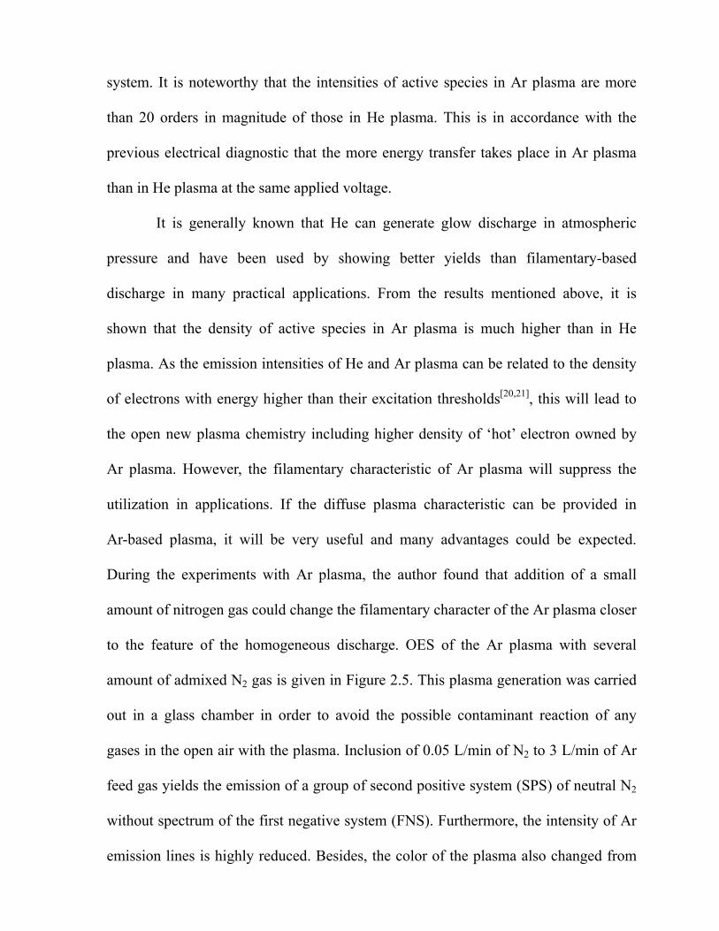
During the experiments with Ar plasma, the author found that addition of a small
amount of nitrogen gas could change the filamentary character of the Ar plasma closer
to the feature of the homogeneous discharge. OES of the Ar plasma with several
amount of admixed N2 gas is given in Figure 2.5. This plasma generation was carried
out in a glass chamber in order to avoid the possible contaminant reaction of any
gases in the open air with the plasma. Inclusion of 0.05 L/min of N2 to 3 L/min of Ar
feed gas yields the emission of a group of second positive system (SPS) of neutral N2
without spectrum of the first negative system (FNS). Furthermore, the intensity of Ar
emission lines is highly reduced. Besides, the color of the plasma also changed from
28

light
Inte
nsity
(cou
nt)
Ar only
Inte
nsity
(cou
nt)
Ar/N2; N2 0.05 L/min
N2
Ar
Inte
nsity
(cou
nt)
Wavelength (nm)
Ar/N2; N2 0.5 L/min
Figure 2.5 Emission spectra of Ar and Ar/N2 plasma at different amount of N2 rate.
29

light blue to violet blue. Increasing the amount of N2 admixed to the higher amount
caused the domination of the N2 emission over Ar emission. Raising the N2 flow rate
over 0.7 L/min extinguished the plasma. Selective excitation of nitrogen species
occurred because transfer energy of Ar excitation threshold (ETh ≈ 13.5 eV) is only
sufficient to excite the SPS N2 (ETh ≈ 11 eV) and not enough for exciting FNS N2+
which having energy threshold of 18.7 eV.
Plasma Temperature
The measurement of gas temperature of the non-equilibrium atmospheric
pressure plasma jet was carried out by two methods. First, the jet effluent along the
axis at its end was directly measured using a thermocouple. Secondly, a piece of
silicon wafer was placed at 2 cm from the torch end where the plasma jet stroke the
wafer directly, and the infrared thermometer was shot on that place every minute. The
measurements were conducted at surrounding temperature of 25. By using these
methods, both information of gas temperature and the effect to the substrate
temperature would be obtained. It was found that both methods yielded a similar
result for He and Ar plasma. The increase in temperature by time extension is
summarized in Figure 2.6. The experimental conditions were 3 L/min of gas feed, 3.5
kV of applied voltage and 68.0 kHz in frequency. From the same starting point, it
appears that the increment of temperature for Ar plasma is more than that for He
plasma, however, those plasmas find their saturated temperature at the same period of
10 min. It needs to be pointed out from this experiment that the temperature of the
30

present
20
22
24
26
28
30
32
34
0 5 10 15 20
Figure 2.6. Temperature increment profile of the He and Ar plasma torch by the time.
Time (min)
Tem
epera
ture
(
)
Ar
He
Tem
pera
ture
()
Time (min)
31

present plasma jet is much closer to room temperature than any other design of
plasma jet.[2,3] It becomes very clear therefore that the present novel plasma torch has
a great possibility to broaden its application, not only to change the surface properties
of polymers, but also for surface modification of temperature-sensitive materials or
even can be applied on tissue engineering. The main reason why the gas discharge
still keeps low in temperature is because of the usage of pulsed power supply. The
characteristic of the pulsed power is its capability to switch the power on and off
repeatingly thousands times during a second. Due to its discontinuity of cycling power,
the pulsed power can be expected to provide plasma temperature stay low.
Verification of low temperature of the plasma jet was also performed by
simply touching it by the hand, as showed in Figure 2.7. The He glow discharge can
strike the bare human skin without causing harm effect. This is because the
transferring of several kilovolts pulsed power to the working gas only to excite the
light electrons and leave the heavy neutral particles unaffected.
Plasma Jet Length Dependency
It is valuable to understand the controlling factors of the plasma jet length
because it will bring benefits to the practical use of the present plasma torch. An
adequate length of plasma jet might be very important so as to enable various and
useful chemical reactions on the substrate surface. Control of the jet length in this
study has been performed through examining the influence of applied voltage and
flow rate of feed gas. He gas was used to execute the initial trials. Figure 2.8 shows
the effect of applied voltage on plasma jet length at different He flow rate using
32

frequency
1 cm
Figure 2.7 Glow He plasma torch in contact with human bare skin.
33

3 L/min
0
10
20
30
40
50
60
2 3 4 5 6 7
9 L/min
)
Figure 2.8 Effect of applied voltage on plasma torch length
at different He flow rate.
20 L/min
Applied voltage (kV)
Jet l
engt
h (m
m
34

frequency of 68 kHz. It is obvious that raising the applied voltage yields increasing of
t length for all feeding rate. This is reasonable as the strength of applied electrical
ield will deter asing the
low rate of H ts in decrease of the jet length.
his fact might be attributed to the shortening of contact time of the fed to the
lectrode surface owing to its high gas fluid velocity. Practically, the use of large
mount of He is not desirable because of higher cost for operation. The flow rate of 3
/min seems to be the necessary and sufficient stream of He gas to sustain the plasma
t. This feeding rate was therefore adopted to generate the plasma jet for its
pplication to the deposition of thin films in the subsequent chapters.
. The
ngth of plasma jet was influenced by the applied voltage and gas flow rate.
je
f mine the amount of charged particles. On the contrary, incre
f e gas from 9 L/min to 20 L/min resul
T
e
a
L
je
a
Conclusion
This chapter describes development and characterization of `Cold
Atmosphere Pressure Plasma Torch` or CAPPLAT. The design was adjusted in which
the stainless belt was placed around the silicone tube covered stainless pipe near its
end for the ease of generating with He and Ar as the working gas. Electrically, the
discharge was a type of homogenous glow, though visually Ar plasma rather showed
filamentary. From the OES results of the plasma jet, the presence of O・, OH・and
various of system of N2 excited species was confirmed when the torch was carried out
in open air. The temperature of plasma jet was found to be lower than 35
le
35

References
1. R.B. Gadri, J.R. Roth, T.C. Montie, et.al., Surf, Coat. Technol., 131, 528, 2000.
Plasma Source Sci. Technol., 7, 282-285, 1998.
3. S.E. Babayan, J.Y. Jeong, V.J. Tu, J. Park, G.S. Selwyn and R.F. Hicks, Plasma
Source Sci. Technol., 7, 286-288, 1998.
Hicks, J. Vac. Sci. Technol. A, 18, 2799, 2000.
5. H. Koinuma, H. Ohkubo and T. Hashimoto, Appl. Phys. Lett, 60, 816, 1992.
7. K.L. Mittal and A. Pizzi, eds., Adhesion Promotion Techniques, Marcel
2. J.Y. Jeong, S.E. Babayan, V.J. Tu, J. Park, I. Henins, R.F. Hicks and G.S. Selwyn,
4. V.J. Tu, J.Y. Jeong, A. Schutze, S.E. Babayan, G. Ding, G.S. Selwyn and R.F.
6. Van Brunt R.J., IEEE Trans. Dielectr. Electr. Insul., 1, 761-784, 1994.
Dekker,
NY 1999.
ma, M. Kogoma, S. Kanazawa, T. Moriwaki and S. Okazaki, J. Phys D:
12 . Okazaki, J. Phys D: Appl. Phys.,
trum. Meth.
14 i, M. Kogoma, M. Uehara and Y. Kimura, J. Phys D: Appl. Phys., 26,
15. Y.Sawada, S.Ogawa, M.Kogoma, Journal of Adhesion, 53 [3-4], 173 (1995)
03).
8. T. Yokoya
Appl. Phys., 23, 374, 1990.
9. F. Massines, A. Rabehi, P. Decomps, R.B. Gadri, P. Segur and C. Mayoux, J of
Appl. Phys., 83, 2950, 1998.
10. S.F. Miralai, E. Monette, R. Bartnikas, G. Czeremuszkin, M. Latreche and M.R.
Wertheimer, Plasmas and Polymers, 5, 63, 2000.
11. I.E. Kieft, E.P v d Laan and E. Stoffels, New J. of Phys., 6, 149, 2004.
. S. Kanazawa, M. Kogoma, T. Moriwaki and S
21, 838, 1988.
13. S. Kanazawa, M. Kogoma, S. Okazaki and T. Moriwaki, Nucl. Ins
Phys.Res. B, 37/38, 842, 1989.
. S. Okazak
889, 1993.
16. F. Massines, P. Segur, N. Gherardi, C. Khamphan, A, Richard, Surf. Coat
Technol., 174-175, 8-14 (20
17. S. Martin, F. Massines, N. Gherardi, C. Jimenez, Surf. Coat Technol., 177-178,
693-698 (2003).
36

18. R.W.B. Pearse, A.G. Gaydon, The Identification of Molecular Spectra. Fourth
19. A. Kuwabara, S. Kuroda, H. Kubota, Plasma Processes and Polymers, 2 (4),
20. o, Pure & Appl. Chem., 70 (6), 1203-1208, 1998.
01.
Edition, Chapman and Hall, 1976.
305-309, 2005.
R. Lamendola and R. d’Agostin
21. F. Palumbo, P. Favia, M. Vulpio, R d'Agostino, Plasmas and Polymers, 6 (3),
163-174, 20
37

CHAPTER III
Poly(methyl methacrylate) Films
Deposited via Non-equilibrium Atmospheric Pressure Plasma
Polymerization with Using Argon as the Working Gas
Abstract
A non-equilibrium atmospheric pressure plasma torch using argon (Ar) for
sustaining plasma h deposit the plasma
pol
composition of the films obtained were examined by FT-IR and XPS analyses. It was
found t level
to the plasma, the plasma transitioned from a filamentary to the glow-like discharge,
resulting in a high retention of monomer structure. Since the optical emission
spectroscopy (OES) study of the plasma did not show any new excited species formed
at higher concentrations of monomer, it is clear that the fragmentation degree of the
monomer in the plasma phase was quite low.
as been developed and it was used to
ymerized methyl methacrylate (PPMMA) films. The chemical structure and
hat when raising the concentration of vaporized monomer to a certain
in
38

Introduction
Previous chapter has described the configuration of the novel non-equilibrium
atmospheric pressure plasma torch together with its electrical characteristic and
optical properties of the discharge. This chapter investigates the application of the
torch for deposition of organic film. Plasma polymerized organic thin films have been
received a great deal of interest because of their unique characteristics such as:
pinhole-free, structurally cross-linked, insoluble and highly adhered to different
ubstrate surfaces. They can potentially offer many practical applications in the field
f mechanics, electronics and optics.[1] Of particular interest are the plasma
thyl methacrylate (PPMMA) films, which have been used as dry
electro
pliment technique to spin-on coating.
s
o
polymerized me
n-beam resist,[2] membranes for gas separators, humidity sensor and optical
devices such as wavelength transformer.[3,4,5]
Spin coating is a physical process that is generally known to be able to
produce thin films from polymer solution with full retention of their functionalities.
However, it is very useful and many advantages would be obtained if the polymer film
can be deposited using plasma polymerization, due to its characteristic of one-step
process, avoiding solvent usage and no volatiles involved. Moreover, the latter
process allows deposition of films with the thickness from nano to micrometer level.
If the monomer fragmentation in the plasma-mediated process can be controlled in
order to gain polymer thin film with full retention of its functional groups, plasma
polymerization method would provide the com
The low pressure plasma assisted processes are the well-established and
become commonly used methods for the deposition of polymer-like films. However,
39
the necessity of expensive vacuum systems is the biggest shortcoming of these
processes in industrial applications besides the limitation to the batch system
processes. Therefore, to overcome these disadvantages, considerable efforts are made
in developing alternative techniques. The non-equilibrium atmospheric pressure
plasmas are one of the most promising methods to deposit polymer films in a more
flexible, reliable, less expensive and continuous way of treatment. Several types of
non-equilibrium atmospheric pressure plasma sources have been successfully used for
depositing films, and they included atmospheric pressure (AP) dielectric barrier
discharge (DBD)[ 6-11] as the most commonly used atmospheric pressure discharge,
AP Plasma Jet, [12-14] and AP plasma chemical vapor deposition (AP-PCVD).[15-16]
However, most of them have been using helium (He) as the working gas to generate
the plasma. If the plasma could be generated with using argon (Ar) as the working gas,
it would bring a great benefit to the technique, because Ar is much less expensive than
He and also because the Ar plasmas have better energy transfer efficiency than the He
plasmas under the same working conditions.[17] We have successfully developed a
non-equilibrium atmospheric pressure plasma torch in which the plasma can be
generated either in He or in Ar gas. For the applications in material processing, we
explore to deposit organic thin film using this system.
The present study reports the plasma polymerization of methyl methacrylate by
non-equilibrium atmospheric pressure plasma torch with using Ar as the working and
carrier gas. It will be shown that the deposited PPMMA films are chemically and
spectroscopically similar to the conventional poly(methyl methacrylate) (PMMA)
synthesized by traditional chain polymerization.
40

Experimental Part
Materials
The films were deposited either on silicon wafers for XPS analyses or on KBr
disks for FT-IR measurements. The substrates were cleaned with acetone under
ultraso
id the direct contact with the process exhaust which may contain
ases, the novel torch has been housed with a reactor and safety outlet
portion
inserted into a glass vessel to make the chamber sealed
rom the ambient air. The exhaustion of gas was done through the vent on the outer
. The stainless tape electrode that circled the outer part of
the sto
nic condition prior to the plasma polymerization. Methyl methacrylate (MMA)
monomer (Wako Chemicals Co.) was used as the organic precursor after purification
through vacuum distillation.
Plasma Polymerization
In order to avo
hazardous g
. The schematic diagram for the non-equilibrium atmospheric pressure plasma
polymerization is shown in Figure 3.1. High voltage power supply (Haiden Lab.
PHF-2K) was connected to the stainless pipe (inner diameter = 4 mm) electrode,
which was embedded in the center of a perforated silicone stopper allowing the gas to
flow through. The stopper was
f
side of the silicone stopper
pper was connected to the ground. Gas mixture consisted of 3.0 L/min of Ar as
the working gas and the admixed monomer gas, which was vaporized by passing
another Ar tube through the room temperature MMA vessel. This mixture was
allowed to flow in through the inlet pipe, and the plasma was ignited by using an
electric source at a fixed frequency of 68.0 kHz. The plasma was generated
41

downstream
42
Figure 3.1. Schematic diagram for non-equilibrium atmospheric pressure
plasma polymerization experiment set-up.
Exhausted toatmosphere
Substrate
HV Power Supply,Haiden Lab PHF-2K
Gas mixture
Stainless pipe
MMA Monomer
Stainless
Glass reactor
Ar Ar
Glass holder
Silicon stopper GND
MPM C7460
Fiber optic

downstream to the substrate which was positioned along as 2.5 cm distance from the
pipe end. The film deposition was carried out for 10 min under various conditions of
carrier gas flow rate and the applied voltage. The characteristic of plasma was
examined by OES, and the as-deposited PPMMA films were characterized by FT-IR
and XPS. OES measurements were performed perpendicularly to the downstream
discharge with a Multiband Plasma-Process Monitor (MPM, Hamamatsu Photonics
C7460). The emission spectra from the plasma source were acquired through the
equipped optical fiber in the range of 200-950 nm. FT-IR analyses were performed to
examine the structure of PPMMA films. Transmission mode was used for FT-IR
easurements on a Jasco FT-IR-8000 spectrophotometer with 64 scans at 4 cm-1
esolution.
SCA instrument, usin binding energy scale
as calibra d by setting the C1s peak at 285 eV. The high resolution scan (0.25 eV
esolution) spectra of C1s region were also measured, and the obtained spectra were
econvoluted using the curve fitting program of MultiPak V.6.1A.
esults and Discussion
as-phase Chemistry
gave rise to a pale purple non-filamentary discharge which resulted in glow-like
m
r XPS measurements were carried out on a Perkin Elmer PHI Model 5600
E g a monochromated Al X-ray source. The
w te
r
d
R
G
The typical Ar plasma at atmospheric pressure consists of many whitish
light-blue streamers leading to the inhomogeneous discharge, which is inexpedient for
plasma polymerization. However, the discharge behavior was changed when the
vaporized MMA monomer in 0.3 L/min Ar carrier gas was added to the Ar plasma. It
43

plasma. It is generally known that the addition of gases such as a halogen, nitrogen or
organic molecules can quench or may extinguish the argon glow discharge plasma due
to efficient energy transfer from Ar metastables to foreign atoms or molecules.[18]
Accordingly, in the present system, the addition of MMA monomer to the atmospheric
pressure Ar plasma made a change in the discharge behavior from filamentary to the
glow-like one owing to this quenching effect.
Optical emission spectroscopy (OES) was performed to determine the nature of
excited species in the Ar plasma with and without the addition of MMA monomer.
Shown in Figure 3.2 are the spectra lines obtained from the pure Ar plasma and the Ar
plasmas containing various concentration of the admixed monomer, which were
obtained by varying the flow rates of the Ar carrier gas. It can be observed from OES
f the pure Ar plasma that the spectra lines of the neutral Ar atoms appear strongly in
m. These lines are in agreement with the spectral Ar lines
ospheric pressure barrier discharge,[19] or in that from hollow
cathod
o
the range of 695 – 921 n
detected in either an atm
e discharge under 1 torr. [20] When the vaporized monomer was introduced by
flowing Ar gas with a flow rate of 0.1 L/min, apart from the Ar lines of Ar which
seemed unchanged in emission intensity, a group of low-intensities lines due to CH
(431 nm) and CO (519 nm) species[21] was found in the region between 350-520 nm.
This indicates that the concentration of MMA in 0.1 L/min Ar gas added to the Ar
plasma is too low to give a certain cooling effect to the Ar plasma, and as a result, a
high degree of monomer fragmentation has been occurred in the plasma bulk due to
the interaction of the high energy electrons with precursor molecules. Increasing the
concentration of monomer by flowing 0.3 L/min Ar gas did not yield the new lines of
44

45
excited
300 450 600 750 900
200000
150000
100000
50000
0
200000
0
150000
100000
50000
0
150000
100000
50000
0
150000
100000
50000
0
30000
20000
10000
[Int
ensi
ty (c
ount
)] (a
.u.)
Ar
Ar/MMA 0.1 L/min
CH (431 nm)
Ar/MMA 0.3 L/min
CO (520 nm)
Ar/MMA 0.4 L/min
Ar/MMA 0.5 L/min
Wavelength [nm]
Figure 3.2. Emission lines of argon and Ar/MMA at different flow rates.
Conditions: Ar 3.0 L/min, applied voltage 4.0 kV, freq. 68.0 kHz.

excited species; however, it can be observed that the intensity of Ar lines has also
ecreased. This confirms that the plasma quenching phenomenon due to the energy
fficient transfer from Ar metastables,[18] particularly the line at 912 nm (one can
ompare this line to the Ar line at 762 nm) to the MMA molecules. The quenching
ffect becomes more pronounced with increasing the monomer gas by feeding 0.5
/min Ar since the emission intensity of Ar lines is decreased by the factor of 5.
urther increase of monomer concentration by flowing more than 0.7 L/min
xtinguished the plasma. Considering that the emission from Ar* decreases when the
onomer feeding rate increases from 0.1 to 0.3 L/min of Ar or even larger, the
uenching reaction in plasma volume at rather high concentration of monomer
dicates a low degree of monomer fragmentation. This is further supported by the
act that no lines of precursor fragments can be observed.
The OES results (showing no new lines of electronically excited species for the
igh concentration of the admixed monomer to Ar plasma) indicate that the
ragmentation of MM negligible, and therefore that the monomer structure will be
ighly retained in the deposited films. The effect of carrier gas flow rate
concentration of monomer) on the quality of films was then investigated by FT-IR
nalysis.
d
e
c
e
L
F
e
m
q
in
f
h
f A is
h
(
a
FT-IR
Figure 3.3 shows the FT-IR spectra of several PPMMA films deposited using
different flow rates of the carrier gas. Those spectra are displaced one in relation to
another to avoid overlaps. It can be observed that, by flowing carrier gas with 0.1
46

L/min
Figure 3.3 FT-IR spectra of PPMMA films deposited at different carrier gas flow rates.
Conditions: Ar 3.0 L/min, applied voltage 4.0 kV, frequency 68.0 kHz.
Ar/MMA 0.5 L/min
Ar/MMA 0.4 L/min
Ar/MMA 0.3 L/min
Ar/MMA 0.1 L/min
Tran
smitt
ance
(a.u
.)
4000 30004600 2000 1000 400
Wavenumber [cm-1]
47
L/min, a weak band at around 1730 cm-1 which is due to the retention of C=O was
btained, while the other organic functional groups were not present. The vigorous
ragmentation occurred in the plasma volume as mentioned above should be taken
to account as one of the reasons of this phenomena. Moreover, the carbonyl double
ond m to be reasonably stable during the reaction as identified by Christina M.Q.
t al ver, surprisingly, by enlarging Ar flow rate to 0.3 L/min, which
orre ds to the point when the plasma turned out to the glow-like discharge,
lmost all characteristics of PMMA spectrum were retained in PPMMA film. Strong
bsorption bands at 1730 and 1460 cm-1 which correspond to the characteristic of
=O stretching of ester carbonyl and deformation of C–H bonds in the methyl group
respectively are evident in the spectrum of PPMMA f . Moreover, two prominent
peaks at 2990 and 2950 cm-1 attributed to the contribution of methyl and methylene
g
g of
plasma polymerization, it is suggested that the polymerization is primarily through the
addition of vinyl radical to carbon-carbon double bond. This is supported by the
absence of C=C absorption bands which usually present at around 1630 cm-1. This is
also in accordance with the findings of Ward et al.[23] when they deposited
poly(acrylic acid) films by atmospheric pressure glow discharge using an ultrasonic
nozzle. The extent of structural retention in the films deposited by monomer feeding
of 0.3, 0.4 and 0.5 L/min Ar carrier gas seems to be the same, i.e. by comparing the
intensity of C=O relative to the intensity of C-H absorption bands. From FT-IR
o
f
in
b s see
.[22] Howe
spon
e
c
a
a
C
ilm
roups and peaks in the region 1145-1270 cm-1 due to C–O–C stretching of the ester
roup are also remarkable. Because free radical polymerization is a typical reaction
48

results, it is interesting to mention that the well-defined chemical structure of our
PPMMA films are resemble to that of conventional PMMA synthesized by chain
polymerization. These films can be obtained directly from MMA monomer using an
atmospheric pressure Ar plasma torch, when the characteristic discharge has
transitioned from the filamentary to the glow-like regime.
Figure 3.4 represents the FT-IR spectra of several PPMMA films deposited
using 3.0 L/min Ar, 0.5 L/min Ar/MMA and frequency 68.0 kHz, in respect to the
differences of applied voltage. For a comparison, the spectrum of conventional
PMMA film prepared by 2000 rpm spin coating (2 wt.-% of PMMA/acetone solution)
is also shown. It can be seen that increasing the applied voltage did not give
significant variations on the chemical structure of the deposited films. The extent of
C=O retention relative to the C-H retention of all the films deposited at difference
applied voltage are comparable to that of the spin coated film. The difference in
intensity could be attributed to the difference in film thick ess, which was found to
increase almost linearly from 215 nm obtained at 3.5 kV to 1080 nm obtained at 5.0
kV, through the measurements by using a surface profiler (ULVAC, Dektak 3ST). It
can also be observed from Figure 3.4 that the inclusion of hydroxyl group around
3500 cm
n
-1 is apparent, and it increases its intensity as a function of applied voltage. In
order to clarify the factors of hydroxyl inclusion, the obtained films were kept in a
desiccator before performing the FT-IR analysis. We found very little difference in
spectra of the films kept in and outside of the desiccator, and this indicates that the
inclusion of hydroxyl groups was mostly because of the incorporation of
49

OH-containing
50
Figure 3.4 FT-IR spectra of PPMMA films deposited at different applied voltage.
Conditions: Ar 3.0 L/min, Ar/MMA 0.5 L/min, frequency 68.0 kHz.
400 1000 200030004000 4600
Wavenumber [cm-1]
Tran
smitt
ance
(a.u
.)
P 5.0 kV
P 3.5 kV
Spin coated PMMA
P 4.0 kV
P 4.5 kV

OH-containing fragments during the film growth rather than the water adsorption
rom the atmospheric air into the voids of the films. This hypothesis is also sustained
y the observation that the OH concentration in our films increases with increasing
e applied voltage (see the figure). The strong similarity in the structure of the
PMMA films with the conventional PMMA concluded by FT-IR analysis could
ecome a confirmation that the non-equilibrium atmospheric pressure Ar plasma torch
one of the effective methods to produce organic thin films that resemble to the
onventionally polymerized ones.
PS
Figure 3.5 shows the typical high resolution C1s spectra of a spin coated
onv
/m
haracteristic of bonding components at different binding energies. The curve-fitted
1s spectrum of conventional PMMA presents three peaks at 285.2 eV, 286.7 eV and
89.0 eV, which are attributed to the C-C/C-H bonds, C-O bonds and O-C=O
unctional groups, respectively. The C1s scan of PPMMA film shows the same
haracteristic bonding to PMMA at the similar binding energies with an additional
f
b
th
P
b
is
c
X
c entional PMMA and a PPMMA film deposited at 4.0 kV with a flow rate of 0.3
L in Ar/MMA, respectively. Those spectra have been curve-fitted to discern
c
C
2
f
c
peak at 287.8 eV that corresponds to the C=O or O-C-O moieties. This peak
could be possibly occurred due to the loss of an ester carbon through the scission of
the ester methoxy.[24] Table 3.1 summarizes the relative abundant percentages of each
functional group estimated from the deconvolution of C1s spectra for the two films.
51

52
Figure 3.5. C1s high resolution of a) PMMA spin coated film and
b) PPMMA film deposited at 4.0 kV, 68.0 kHz and Ar/MMA 0.3 L/min.
N(E
)/E (a
.u.)
Binding Energy (eV)
292 286 280
a)
290 288 284
b)
N(E
)/E (a
.u.)
290 285 280
Binding Energy (eV)
52
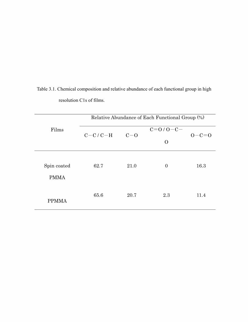
Table 3.1. Chemical composition and relative abundance of each functional group in high
resolution C1s of films.
Relative Abundance of Each Functional Group (%)
Films C-C / C-H
O C-
O O-C=O
C= / O- C-O
Spin coated
PMMA
62.7 21.0 0 16.3
PPMMA65.6 20.7 2.3 11.4
53

Compared to the conventional PMMA film, the relative abundance values of each
-
C=O gro group in PPMMA relative to the PMMA
indicates the loss of ester ation
of the nctional group of C=O or O-C-O that was absent in PMMA. In
general, good comparable features of PMMA and PPMM ilm analyzed by XPS
study can make a confirmation that even the uppermost surface of PPMMA film
deposited by the non equilibrium atmospheric pressure
characteristic feature with conventional PMMA surface.
Fro a practical po view, the ivity of the osition tow ygen
traces is an important issue. The experiments in which the addition of oxygen was
erefore conducted in order to know the influence of the possible oxidation reaction
the reactor to the structure of deposited film. The addition of 50 mL/min oxygen
low into reactor was found not to affect the chemical structure of film, leading to
plication that this process might be utilized in open air (in case to deposit the
omplex shape) with the same achievement by using a reactor.
onclusion
non-equilibrium atmospheric pressure plasma torch that can sustain Ar plasma has
functional group in PPMMA film are close, with the exception of the retention of O
ups. Lower percentage of this
functionalities, which might be responsible for the form
new fu
A f
plasma torch has similar
m int of sensit dep ard ox
th
in
f
im
c
C
A
54

been developed and successfully demonstrated the ability to be used to obtain organic
in films through the plasma polymerization of MMA. OES study showed a low
effective methods to deposit organic thin films with characteristics similar to the
corresponding conventional polymers.
References
1. A. Hiratsuka and I. Karube, Electroanalysis, 12, 695-702 (2000).
4. A.R.K. Ralston, J.A. Tobin, S.S. Bajikar, D.D. Denton, Sensors and Actuators B, 22,
6. T. Yokoyama, M. Kogoma, S. Kanazawa, T. Moriwaki and S. Okazaki, J. Phys. D:
Appl. Phys., 23, 374-377 (1990).
, S. Ogawa and M. Kogoma, J. Phys D: Appl. Phys., 28, 1661-1669
8. R. Prat, Y.J. Koh, Y. Bubukutty, M. Kogoma, S. Okazaki, M. Kodama, Polymer, 41,
th
degree of fragmentation in plasma phase when the admixed MMA was flowed by a
flux of 0.3 L/min Ar carrier gas. These conditions can therefore lead to a high degree
of monomer retention in the film structure. FT-IR and XPS analyses confirm that
PPMMA films have similar chemical structure and composition to those of the
conventional polymer. Finally, the present paper reveals that the non-equilibrium
atmospheric pressure plasma torch using Ar as the working gas can become one of the
2. S. Morita, J. Tamano, S. Hattori and M. Ieda, Journal of Applied Physics, 51,
3938-3941 (1980).
3. C. Zhang, J. Wyatt, D.H. Weinkauf, Polymer, 45, 7665-7671 (2004).
139 (1994).
5. H.S. Jeon, J. Wyatt, D. Harper-Nixon, D.H. Weinkauf, J. of Polym. Sci., Part B:
Polym. Physics, 42, 2522-2530 (2004).
7. Y. Sawada
(1995).
7355-7360 (2000).
55

9. C.P. Klages, K. Hopfner, N. Klake and R. Thyen, Plasmas and Polymers, 5, 79-89
(2000).
and R. Hippler, Plasmas and Polymers, 6, 237-266 (2001).
11. R. Foest, F. Adler, F. Sigeneger, M. Schmidt, Surf. Coat. Technol., 163-164,
323-330 (2003).
Sources Sci. Technol., 7, 286-288 (1998).
13. S.E Babayan, J.Y. Jeong, A. Schutze, V.J. Tu, M. Moravej, G.S. Selwyn and R.F.
Hicks, Plasma Sources Sci. Technol., 10, 573-578 (2001).
Technol., 11, 97-103 (2002).
10. A. Sonnenfeld, T.M. Tun, L. Zajícková, K.V. Kozlov, H.E. Wagner, J.F. Behnke
12. S.E Babayan, J.Y. Jeong, V.J. Tu, J. Park, G.S. Selwyn and R.F. Hicks, Plasma
14. G.R. Nowling, S.E. Babayan, V. Jankovic and R.F. Hicks, Plasmas Sources Sci.
5. Y. Mori, K. Yoshii, H. Kakiuchi and K. Yasutake, Rev. Sci. Instrum., 71, 3173
16. H. Kakiuchi, Y. Nakahama, H. Ohmi, K. Yasutake, K. Yoshii and Y. Mori, Thin
3).
6, 465 (2001).
21. ntification of Molecular Spectra, Fourth
22. and J.B. Maciel., J. Braz. Chem. Soc., 9, 521
24. K. Gleason, Chem. Vap. Deposition, 12, 59 (2006).
1
(2000).
Solid Films, 479, 17-23 (2005).
17. S. Wang, V. Schulz-von der Gathen, and H.F. Dobele, Applied Physics Letters,
83, 3272-3274 (200
18. K. Wagatsuma, Spectrochimica Acta Part B: Atomic Spectroscopy, 5
19. S.E. Alexandrov, N. McSporran, M.L. Hitchman, Chem. Vap. Deposition, 11, 481
(2005).
20. A. Bogaerts, R. Gijbels, J. Vlcek, Spectrochimica Acta Part B, 53, 1517 (1998).
R.W.B. Pearse, A.G. Gaydon, The Ide
Edition, Chapman and Hall, (1976).
Christina M.Q., G.G.B. de Souza
(1998).
23. L.J. Ward, W.C.E. Schofield, J.P.S. Badyal, Chem. Mater., 15, 1466 (2003).
T.B. Casserly and K.
56

n Plasma Torch
plasma torch that can be generated
either in He or Ar gas by using pulsed high voltage power supply with the discharge
to deposit silicon dioxide film from hexamethyldisiloxane (HMDSO) precursor
ul
HM jected to the Ar plasma torch was limited up to 100 mL/min to ensure
spect
ogen (N2)
as has been admixed to the Ar gas as the working gas. When the composition ratio of
r and N2 flow gas was 30:1, the regime behavior was transformed from filamentary
CHAPTER IV
Non-equilibrium Atmospheric Pressure Argo
For Deposition of Thin Silicon Oxide Film
Abstract
A non-equilibrium atmospheric pressure
temperature in the range of 22-35 has been developed. This system has been used
diluted in oxygen carrier gas. It was concluded that Ar plasma was more powerf
than He plasma for depositing SiO2-like film in terms of both quality and deposition
rates at the same applied power, frequency and gas composition. The feed rate of
DSO/O2 in
inorganic coatings were deposited. In order to improve the quality of the visual a
without deteriorating the inorganic feature of the film, a small amount of nitr
g
A
57

into glow-like discharge owing to the quenching effect of the N2 gas on Ar plasma.
hese conditions can therefore result in better property of the film with no appearance
of the small particles on the film surface.
Introduction
As reported in the previous chapter the non-equilibrium atmospheric pressure
Ar yl
methacrylate) ilm obtained
conventionally. This chapter will report the study of deposition of SiO2-like film from
monomer having an inorganic feature (hexamethyldisiloxane, HMDSO) using an
ic pressure Ar plasma torch as well. SiO2-like films are greatly of interest
becaus
more flexible, reliable, less expensive and continuous way of treatment. Several types
T
,
plasma torch can be used to deposit film from organic monomer (meth
which has similar characteristics to the PMMA f
atmospher
e of having excellent physical and chemical properties such as optical
transparency, chemical inertness, scratch resistant and sufficient hardness, thus are
widely used in many fields of technological applications. Microelectronics, optic,
biomedical, metal and polymer protection coatings and food packaging are the fields
that find the utilization of silicon oxide film in their industry applications.
At present, the well-established method which is commonly utilized for the
deposition of organic or inorganic films is low pressure plasma-assisted processes.
However, the necessity of an expensive vacuum system is the biggest shortcoming of
this process in the industrial applications, besides the limitation to the batch system
processes. Therefore, to overcome those disadvantages, considerable efforts are
crucial in developing the alternative techniques. The non-equilibrium atmospheric
pressure plasma is one of the most promising methods to deposit polymer films in the
58
of non-equilibrium atmospheric pressure plasma sources have been successfully used
for depositing SiO2 films to substrate surface such as atmospheric pressure (AP)
dielectric barrier discharge (DBD)[1-4] as the most commonly used atmospheric
arge, AP Plasma Jet, [5,6] and AP plasma chemical vapor deposition
(AP-P
SO as the
precur
pressure disch
CVD).[7,8] However, most of them have used helium (He) as the working gas to
generate the plasma. If the plasma can be generated with using argon (Ar) as the
working gas, it will bring a great benefit to the technique as Ar gas is much less
expensive than He gas. Moreover, Ar plasmas shows better energy transfer efficiency
than the He plasmas under the same working conditions.[9] We have successfully
developed a non-equilibrium atmospheric pressure plasma torch in which the
plasma can be generated either in He or in Ar gas. This system has been used to
deposit an organic film (PPMMA) and exhibits similar chemical characteristics to the
spin coated conventional PMMA film.[10]
The present research reports the deposition of SiO2-like films by means of a
non-equilibrium atmospheric pressure Ar plasma torch using HMD
sor diluted in oxygen. The film deposited using He plasma at the same
condition is also shown for the comparison. The properties of deposited films have
been characterized by FT-IR, XPS and SEM as well as laser microscope.
Experimental
The schematic diagram for the atmospheric pressure plasma polymerization is
shown in Figure 4.1. High voltage power supply (Haiden Lab PHF-2K) was
59
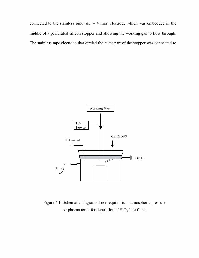
connected to the stainless pipe (φin. = 4 mm) electrode which was embedded in the
middle of a perforated silicon stopper and allowing the working gas to flow through.
The stainless tape electrode that circled the outer part of the stopper was connected to
the
Figure 4.1. Schematic diagram of non-equilibrium atmospheric pressure
Ar plasma torch for deposition of SiO2-like films.
OES
HV Power
Working Gas
O2/HMDSO Exhausted
GND
60

the ground. 3.0 L/min of working gas (He or Ar) was allowed to flow through the pipe
nd the plasma was generated at the frequency of 68.0 kHz downstream to the
ubstrate which was positioned along 2.5 cm distance from the stainless pipe
lectrode.
HMDSO monomer that was stored in room temperature was diluted in the
xygen carrier gas. Its vapor was introduced separately into the middle of the plasma
t downstream to the substrate surface at a different oxygen flow rate. Polymer films
ere deposited on KBr disk for FT-IR analysis and silicon wafer for the other
easurements. All of deposition processes were carried out for 10 minutes without
ubstrate heating.
Optical emission spectroscopy (OES) measurements were performed
erpendicularly to the plasma jet with a Multiband Plasma-Process Monitor (MPM,
amamatsu Photonics C7460). The emission spectra from the plasma source were
cquired through the equipped optical fiber in the range of 200-950 nm. FT-IR
nalyses were performed to examine the chemical structure of SiO2-like films.
Transmission mode was used for FT-IR measurement on a Jasco FT-IR-8000
spectrophotome surements were
carried out by a Perkin Elmer PHI Model 5600 ESCA instrument, using a
monochromated Al X-ray source. The binding energy scale was calibrated by setting
the C1s peak at 285 eV. Carbon (C1s), oxygen (O1s) and silicon (Si2p) atomic
a
s
e
o
je
w
m
s
p
H
a
a
ter with 64 scans at 4 cm-1 resolution. XPS mea
61

compositions were also evaluated. The surface morphologies of the films were
bserved by both a scanning microscope electron (SEM; Hitachi S5000) and a laser
icroscope (Keyence VK-9500).
s deposited by means of a non-equilibrium atmospheric pressure plasma
torch u
2.b.) retained almost all characteristics of the monomer. In addition,
new ab
o
m
Results and Discussion
Effect of Working Gas
Figure 4.2 shows the FT-IR spectrum of HMDSO monomer and plasma polymerized
HMDSO film
sing He and Ar as the working gas, in which all the other parameters were kept
constant. The spectrum of HMDSO monomer (Fig. 4.2.a) exhibits the absorbance
bands of C–H stretching in Si–CH3 at 2965 cm-1, Si–CH3 bending at 1260 cm-1, cm-1,
Si–O–Si stretching at 1020 cm-1 and Si–CH3 rocking vibration at 850 cm-1.[11,12]
When the He working gas was used for the deposition, the chemical structure
of the film (Fig. 4.
sorption bands which were absent in the monomer spectrum are recognized in
the spectrum of plasma polymerized SiO2-like film, i.e. Si–OH band at 930 cm-1 and
the broadband around 3400 cm-1 and also another Si–O–Si network around 450 cm-1.
However, when the deposition was carried out by using Ar plasma jet while keeping
all other parameters the same, the chemical structure of the film had been changed
significantly, i.e. no –CH3 absorption band was detected which resulting in an
inorganic film (Fig. 4.2.c). This SiO2-like film deposited using Ar plasma without
substrate heating seemed indistinguishable from the SiO2 film obtained by Babayan
et.al.,[6] which was deposited by atmospheric pressure plasma He jet using
62

tetraethoxysilane with heating the substrate to 115. Additionally, as can be seen
from the figure, the difference of the band intensities in both of SiO2-like films spectra
indicates that the deposition carrying by Ar plasma has a higher growth rate than that
by
Figure 4.2. FTIR spectrum of a) HMDSO monomer and the corresponding of
Conditions: flow gas 3.0 L/min, applied voltage 3.5 kV, f 68.0 kHz
and O
400
Si-O-Si
the deposited films using b) He plasma torch and c) Ar plasma torch.
2/HMDSO 50 mL/min.
1000 200030004000
Wavenumber [cm-1]
Abs
orba
nce
(a.u
.)
a)
c)
b)
C-H
O-H
Si-CH3
Si-OH
63

by He plasma. In order to confirm this suggestion, the absorbance of Si–O–Si bond at
070 cm-1 of the films deposited in He and Ar plasmas was plotted against the
eposition time through FT-IR measurements, and the results are shown in Figure 4.3.
he plot exhibits that the absorbance of the characteristic band of films deposited by
e and Ar plasma have similar tendency, i.e. increases with deposition time. However,
e magnitude is larger for the sample prepared under Ar plasma than sample prepared
nder He plasma. As it is known that the absorbance is proportional to the thickness
f the sample, thus the gro rate (thickness per unit time) of the film deposition is
aster in Ar than tha He. The difference in working gas to generate the atmospheric
ressure plasma lead a conclusion that Ar plasma can deposit SiO2 ilm more
fficiently than the He plasma in terms of film composition and deposition rate.
It is very important to understand the reasons of why the termination
entioned above could have occurred. Wang et al.[9] found that the temperature at the
xit of the nozzle of Ar/O2 RF plasma jet is about 100 K higher than that for the He/O2
lasma jet under the same conditions of the input power, the flow rate and
omposition of gas, which tells that the efficiently of gas heating is much better in the
orme
alues in the rang
for both of He and hapter II. We therefore examine the
1
d
T
H
th
u
o wth
f t in
p s to -like f
e
m
e
p
c
f r plasma. However, the gas temperature of our plasma jet showed almost similar
v e of 22-35 (the increment as a function of the processing time)
Ar plasmas as discussed in C
64

optical emission spectroscopy to interpret the question.
0.1
0.2
0.3
0.4
0.5
0.6
0
0 5 10 15 20
Abs
orba
nce
Deposition time (min)
Figure 4.3. Absorbance of Si–O–Si bond at 1070 cm-1 of the films deposited
in He () and Ar () plasma plotted against deposition time.
65

Optical Emission Spectroscopy (OES)
OES has been performed to get some insight of deposition process of SiO2-like
ilms from the chemistry of plasma-phase. Shown in Figure 4.4 are the typical
mission spectra of He and Ar plasma jet recorded in the wavelength range from 200
900 nm. The emission spectrum of He plasma contains spectral bands of He species
ith the most intense line at 706.5 nm (33S 3P).[13,14] The spectrum also
cludes a group of N2 emission in the form of first negative system and second
ositive system, as well as the population of atomic oxygen at 777.4 nm and 844.6 nm.
hese signa nds are the consequence of N2 and O2 impurities in the reactor which
re readily zed and excited through the energy transfer of Penning collisions.[15,16]
hen the plasma is generated, it should be noted that the discharge is mainly based on
elium, as the emission intensity of He is dominant in the spectrum. In contrast to He,
e spectum of Ar plasma shows highly intense electronically excited Ar neutrals lines
ing around 700-900 nm without the presence of any additional lines of impurity.
his m he
xcitation thresho xcite
e first negative system of nitrogen at 391.4 nm which needs 18.7 eV[17], or to emit
e atomic oxygen atom at 777.4 nm that requires at least 16 eV through a single-step
issociative excitation.[18] These lines are quite similar to the spectral Ar lines either
rom an atmospheric pressure barrier discharge[19] or that from hollow cathode
f
e
to
w 2
in
p
T l ba
ionia
W
h
th
ly
T ight be due to the fact that the energy of Ar metastables (11.5 eV) or t
e ld (13.5 eV) are not energetically sufficient enough either to e
th
th
d
f
66

discharge under 1 torr.[20]
Despite the information of active species recorded at particular wavelengths
rom He and Ar plasma, one can see that the relative emission intensities of the lines
f
from
a) He plasma 6000
4500 3000 1500
0
0 300 450 750 900600
N2 (
Seco
nd P
ositi
ve S
yste
m)
N2+ (First Negative System)
391.
4
He,
588
He lines
O a
tom
, 844
.6
, 925
He,
706
O a
tom
, 777
.4
He 2
b) Ar plasma 200000
150000
100000
0
0 300 450 750 900600
50000
Ar lines
Figure 4.4. Typical optical emission spectrum of a) He and b) Ar plasma torch.
and fre
[Int
ensi
ty (c
ount
)] (a
.u.)
Wavelength [nm]
Discharge parameters: gas flow 3.0 L/min, applied voltage 3.5 kV
quency 68.0 kHz.
67

ose plasma are very different from each other, which will affect the behavior
f the high-energy tail of the electron energy distribution functions (EEDF). By taking
to account that the emission intensities of He and Ar plasma can be related to the
ensity of electrons with energy higher than their excitation thresholds, 23.0 eV and
3.5 eV respectively,[21,22] it could be deduced that comparing to the He plasma, the
hape of EEDF curve of Ar plasma shifts to the higher energy level, on account that
e population of high energy electrons increases more rapidly than that of the low
nergy ones. This means that even though the electron energy of Ar plasma is lower
an tha He plasma, its density is much larger than He plasma. As a result, when
xygen precursor are injected to the Ar plasma, much population of oxygen and
ilicon containing active species contributing to the film formation are produced more
an in He plasma. Taking it additionally into account that almost all covalent bond in
MDSO and diatomic oxygen could be dissociated by Ar plasma, it is reasonably
nderstood that Ar plasma can deposit more rapidly the films with more inorganic
haracteristics than by using He plasma as shown in FT-IR study.
f HMDSO prec r gas. It is shown that the concentration of
ll active species in He and Ar plasmas are depopulated with the precursor admixture
the plasma. In addition, the reaction involving high energy electrons leads to the
mission of new species which were absent in the pure He and Ar plasma. As shown
rom thf
o
in
d
1
s
th
e
th t of
ando
s
th
H
u
c
Figure 4.5 exhibits the emission spectra of He and Ar plasma jet with injection
o ursor diluted in O2 carrie
a
to
e
68

in Figure 4.5.a, the highest intensity is recorded at 777.4 nm attributed to O atom,
hich supports the above explanation that as the content of O2 increases by injection
the He plasma, the He threshold energy is consumed and lead to the dissociative
w
to
excit
1500
1000
500
0
0 300 450 750 900600
OH
, 306
.4
O a
tom
, 777
.4
He,
706
.5
CH
, 431
a) He – O2/HMDSO
[Int
ensi
ty (c
ount
)] (a
.u.)
b) Ar – O /HMDSO
0 300 450 750 900600
50000
25000
0
2
OH
, 306
.4
75000
100000
Wavelength [nm]
Figur rch. e 4.5. Emission spectrum of a) He-O2/HMDSO and b) Ar-O2/HMDSO plasma to
Discharge parameters: gas flow 3.0 L/min, applied voltage 3.5 kV,
frequency 68.0 kHz and O2/HMDSO 50 mL/min.
69

excitation of oxygen. Other product of precursor dissociation through the similar
eaction is CH line at 431 nm recognized only in He–O2/HMDSO plasma (Fig. 4.5.a),
hich can reflect the incorporation of carbon containing group on the deposit film.
oreover, OH emission at 306.1 nm is clearly observed and this species shows more
tensely in Ar-O2-HMDSO plasma (Fig 4.5.b). The identification of OH in both
lasmas confirms the inclusion of silanol group occurs during the film growth more
kely than by the oxidation reaction post deposition.
ffec Carrier Gas Flow Rate
e effect of O2 carrier gas flow rate on the chemical structure of the films
naly by FT-IR spectra is shown in Figure 4.6. These experiments were using 3.0
/min flow of Ar gas to generate the plasma torch. The flow rates of oxygen through
e bubbler of HMDSO vessel at constant temperature were between 30 to 300
l/min resulting in increasing concentration of HMDSO from 555 to 5048 ppm. It
an be seen that by using O2 flow rate from 30 mL/min to 100 mL/min to vaporize the
xhibited by asing
e O2 flow rate to 200 and 300 m ganic moieties to the
hemical structure of films. Besides the existence of –CH3 groups at 2965 cm-1 and
260 cm-1, one also can observe the evolution of another –CH3 around 850 cm-1 which
r
w
M
in
p
li
E t of
Th
zeda
L
th
m
c
precursor introduced to Ar plasma, the films obtained have inorganic characteristic as
e no detection of hydrocarbon group in the spectra. However, incre
th L/min leads to the growing or
c
1
70
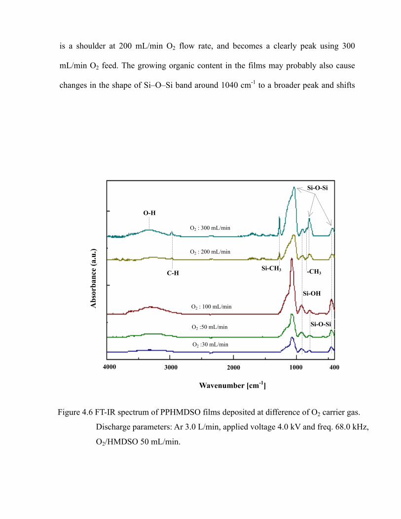
is a shoulder at 200 mL/min O2 flow rate, and becomes a clearly peak using 300
L/min O2 feed. The growing organic content in the films may probably also cause
hanges in the shape of Si–O–Si band around 1040 cm-1 to a broader peak and shifts
m
c
the
Si-O-Si
Figure 4.6 FT
Discharge parameters: Ar 3.0 L/min, applied voltage 4.0 kV and freq. 68.0 kHz,
-IR spectrum of PPHMDSO films deposited at difference of O2 carrier gas.
O2/HMDSO 50 mL/min.
400 1000 2000 3000 4000
Wavenumber [cm-1]
Abs
orba
nce
(a.u
.)
O2 :30 mL/min
O2 : 200 mL/min
O : 100 mL/min2
O :50 mL/min 2
O : 300 mL/min2
C-H
O-H
Si-CH3 -CH3
Si-OH
Si-O-Si
71

the peak to lower wavenumbers.[23] It is acceptable to understand that the electric
nergy consumed for the activation of precursor will be gradually insufficient by
creasing precursor concentration. In our plasma torch system the concentration of
MDSO allowable for making a complete chemical transformation from HMDSO to
iO2 should be when the flow rate of oxygen carrier gas was lower than 100 mL/min
nder the applied voltage of 4.0 kV.
PS Study
The chemical composition of the films was also investigated by XPS analysis.
he cal ted percentages of silicon, carbon and oxygen, as a function of O2 carrier
as flow e are shown in Figure 4.7. Even the carbon containing moieties were not
etected in FT-IR analysis, the concentration of the atomic carbon on the top surface
f the films still could be identified by
an 6 %) is present on the films deposited by feeding the O2 carrier gas up to 100
L/min. As shown in the figure, increasing O
f carbon content and a substantial decrease of oxygen component, while the
FT-IR study that the increase of carbon content of
e film, which is identical to the growing of organic moieties in the film formation,
rises when the HMDSO was injected by feeding the oxygen with the flow rate higher
e
in
H
S
u
X
T cula
ratg
d
o XPS. A quite low concentration of carbon (less
th
m 2 flow rate leads to a significant increase
o
percentage of silicon varies a little, that is from 28.8 % to 26.0 %. These results from
XPS study confirm the results from
th
a
72

than 100 mL/min.
30
45
75
O60
Si
0
15
0 50 100 150 200 250 300 350
C
Ato
mic
con
cent
ratio
n (%
)
O flow rate (mL/min)2
Figure 4.7. Relationship of surface atomic percentages of C, O and Si in the
2
film as a function of O carrier gas flow rates.
73

Improvement of Visual Aspect of Deposited Films
All of deposit films obtained using Ar plasma with O2-HMDSO mixtures were
und to yield powder formation on their surface. The observation of the sample using
anning electron microscope depicted in Figure 4.8 shows the unexpected powder
ontamination on the film surface. The powderous materials which were probably
rmed due to the gas phase nucleation[22] are the possible results of reaction between
e monomer containing inorganic material and the filamentary Ar discharge in the
resence o ygen.
A lot of experiments have been performed in order to improve the quality of
e films. of the thoughts is how to generate a glow discharge based on Ar gas,
, to assist the process of deposition. We finally examine
the experiments by using the combination of Ar and N2 to generate the plasma. The
nature of filamentary discharge of Ar plasma has been reduced remarkably when a
small amount of N2 was admixed to Ar as a source gas. This is reasonable since the N2
has a function to give a quenching ma. Investigation of the
discharge behavior based on mixed Ar and N2 revealed that the best combination of Ar
2
at the light intensity appeared to be homogenous, which resembled to the glow
ischarge generated by He gas. Therefore, this glow-like discharge with a mixture of
r and N2 as the working gas was utilized to deposit HMDSO film onto substrate with
fo
sc
c
fo
th
p f ox
Oneth
instead of the filamentary one
effect to the Ar plas
and N should be 30:1 in flow rate ratio to give rise a glow-like discharge, in the sense
th
d
A
74

the same schematic arrangement as before.
FT-IR spectrum of the film can be seen in Figure 4.9. The film has been
0.1 L/min N2 at applied voltage
deposited by using a mixture gas of 3.0 L/min Ar and
4.0 kV
Figure 4.8. A SEM image of film surface deposited using pure
Ar plasma and O2/HMDSO admixture.
75

Si-O-Si
76
Figure 4.9. FT-IR spectrum of SiO2-like film deposited using glow-like Ar-N2
discharge (a) and the comparison of film deposited using Ar as the working gas (b).
Conditions: Ar 3.0 L/min, N2 0.1 L/min, applied voltage 4.0 kV and freq 68.0 kHz,
O2-HMDSO 50 mL/min.
4001000 200030004000
Wavenumber [cm-1]
O-H
Abs
orba
nce
(a.u
.)
b) pure Ar plasma
a
Si-OH
) Ar/N2 plasma

4.0 kV, frequency 68.0 kHz and 50 mL/min O2-HMDSO. It is observed that the
hemical structure of the film deposited using Ar/N2 plasma shows no remarkable
ifference from that of the film deposited using pure Ar plasma at same conditions,
articularly no organic residue is detected. Moreover, the spectrum also does not show
ny absorption band of nitrogen-containing functional groups. The quality of the film
ven exhibits better property since the silanol groups has a smaller intensity, which
ill lead to a better chemical stability of the coatings.
The visual aspect of the film deposited using Ar/N2 plasma also shows better
ropert an the film deposited by Ar plasma since the powderous region is not
bserve n the ilm. The dense transparent film obtained by Ar/N2
lasma h the thickness of 300 nm through the measurements by using a laser
icroscope (Keyence VK-9500) seems quite similar to the film deposited using glow
ischarge of H re 4.10 shows the three-dimensional image of that
iO2-like film made by Ar/N2 ilicon wafer that was taken by
laser microscope. A very smooth surf rical particles on it can be
b
v
r/N plasma. From these results, it can be concluded that the Ar/N2 plasma is one of
e great potential plasmas and more powerful than the He plasma for depositing
iO2-like films from organosilicon monomer. More experiments based on Ar/N2
c
d
p
a
e
w
p y th
d o
wit
o surface of the f
p
m
d e plasma. Figu
S plasma deposited on the s
a ace without any sphe
o served in that figure. In addition, the thickness of the film appeared to be uniform
er the Si wafer surface confirming the homogeneous discharge characteristic of the o
A 2
th
S
77

plasma in place of using He plasma to deposit high quality silica film are still under
vestigation in our laboratory.
in
Figure 4.10. Three dimensional image of SiO2-like film deposited on Si wafer
Si wafer surface
Film surface
using a glow-like Ar/N2 plasma with O2/HMDSO admixture.
78

Conclusion
A non-equilibrium atmospheric pressure plasma torch that can be sustained
ither with He or Ar gas has been successfully developed to operate at room
mperature. The preparation of SiO2-like film by means of the plasma torch was
vestigated using HMDSO as monomer and oxygen as carrier gas. It was found that
lasma system based on Ar gas can produce SiO2-like deposit film much better in
hemical composition and growth rate than the film deposited based on He plasma.
y using O2 gas with a flux lower than 100 mL/min through the bubbler, it is possible
obtain the inorganic coating film by atmospheric pressure Ar plasma torch even
ithout substrate heating. In order to improve the quality of the film, homogeneous
ischarge based on Ar gas is likely to be used to assist the deposition. It has been
hown that the addition of small amount of N2 gas could quench the Ar plasma and
ielded a transition of a plasma regime from the filamentary to glow-like discharge
hen the
ischarge revealed better quality of the deposit film than that produced by using the
Ar plasma and can become one of the promising alternatives for substituting the
xpensive He gas in generating plasma at atmospheric pressure.
e
te
in
p
c
B
to
w
d
s
y
w composition ratio of Ar and N is 30:1. Application of Ar/N glow-like 2 2
d
pure
e
79

References
1. Y. S
(1995).
4. L. O'Neill, L.-A. O'Hare, S. R. Leadley, A. J. Goodwin, Chem. Vap. Dep., 11,
6. S.E Babayan, J.Y. Jeong, A. Schutze, V.J. Tu, M. Moravej, G.S. Selwyn and R.F.
8. H. Kakiuchi, Y. Nakahama, H. Ohmi, K. Yasutake, K. Yoshii and Y. Mori, Thin
10. Tota P.K., S. Kuroda and H. Kubota, Plasma Processes and Polymers, accepted.
13. R.W.B. Pearse, A.G. Gaydon, The Identification of Molecular Spectra. Fourth
Edition, Chapman and Hall, 1976.
4. A. Kuwabara, S. Kuroda, H. Kubota, Plasma Processes and Polymers, 2, 305-309
(2005).
awada, S. Ogawa and M. Kogoma, J. Phys D: Appl. Phys., 28, 1661-1669
2. R. Foest, F. Adler, F. Sigeneger, M. Schmidt, Surf. Coat. Technol., 163-164,
323-330 (2003).
3. L.J. Ward, W.C.E. Schofield and J.P.S. Badyal, Langmuir, 19, 2110-2114 (2003).
477-479 (2005).
5. S.E Babayan, J.Y. Jeong, V.J. Tu, J. Park, G.S. Selwyn and R.F. Hicks, Plasma
Sources Sci. Technol., 7, 286-288 (1998).
Hicks, Plasma Sources Sci. Technol., 10, 573-578 (2001).
7. Y. Mori, K. Yoshii, H. Kakiuchi and K. Yasutake, Rev. Sci. Instrum., 71, 3173
(2000).
Solid Films, 479, 17-23 (2005).
9. S. Wang, V. Schulz-von der Gathen and H.F. Dobele, Applied Physics Letters, 83,
3272-3274 (2003).
11. Sang Hee Lee and Duck Chool Lee, Thin Solid Films, 325, 83-86 (1998).
12. M. Walker, K. -M. Baumgärtner, J. Feichtinger, M. Kaiser, A. Schulz and E.
Räuchle, Vacuum, 57, 387-397 (2000).
1
80

15. O. Goossens, E. Dekempeneer, D. Vangeneugden, R. Van de Leest and C. Leys,
Surf. Coat. Technol., 142-144, 474-481 (2001).
16. V. Poenariu, M. R. Wertheimer, R. Bartnikas, Plasma Processes and Polymers, 3,
17-29 (2006).
m, Shaista Zeb, Shujaat Ali, A. Waheed, M. Zakaullah, Plasma
18. nd, A. Freilich, J. Lopez, Z. Zhao, W. Zhu and K. Becker, New Journal of
19. an, Chemical Vapor Deposition, 11,
22. tino, Plasmas and Polymers, 6, 163-174
23. ol., 201, 189 (2006).
ippler, Plasmas and Polymers, 6, 237-266 (2001).
17. A. Qayyu
Chemistry and Plasma Processing, 25, 325-351 (2005).
A. Belki
Physics, 7, 90 (2005).
S.E. Alexandrov, N. McSporran, M. L. Hitchm
481-490 (2005).
20. A. Bogaerts, R. Gijbels, J. Vlcek, Spectrochimica Acta Part B, 53 (11), 1517-1526
(1998).
21. R. Lamendola and R. d’Agostino, Pure & Appl. Chem., 70 (6), 1203-1208 (1998).
F. Palumbo, P. Favia, M. Vulpio, R d'Agos
(2001).
A. Pfuch, A. Heft, R. Weidl and K. Lang, Surf. Coat. Techn
24. A. Sonnenfeld, T.M. Tun, L. Zajícková, K.V. Kozlov, H.E. Wagner, J.F. Behnke
and R. H
81

82

83

84

85

86

87

88

89

90

91

92

93

94

95

96

97

98

99

100

101

102

CHAPTER VI
SUMMARY
The primary aim of the work described in this thesis focuses to the
development of novel non-equilibrium atmospheric pressure plasma and its
application to deposit two types of thin solid films; organic films and inorganic films,
based on operation by using argon (Ar) as the working gas. In addition to the
deposition, attention was directed toward the properties of these films through various
characterization methods. The second objective is intended to explore the usage of
low pressure plasma to induce graft polymerization of methyl methacrylate onto kenaf
fiber having relatively high content of lignin.
The thesis begins in Chapter I with a review about plasma, included the
history, low temperature plasma parameters, application in polymerization and some
problems that still exists during its employment in industry. Based on trying to
overcome those problems and learning from many reviewing literatures regarding
plasma technology, we have successfully developed a novel plasma jet source that we
named it by “Cold Atmosphere Pressure Plasma Torch” or CAPPLAT. It is operated
with pulse-modulated high voltage to yield a low temperature discharge at
103

atmospheric pressure. Configuration of the torch as well as its characterization of the
lasma jet is described in Chapter II. Electrical diagnostic clarifies that the discharge
a type of homogeneous glow both for helium (He) and Ar plasma as shown by no
appearance of spiky lines in their time-dependent current curves. Results from optical
emission spectroscopy (OES) showed that reactiv ・, OH・ and
various of N2 system were prese sma was generated in open air.
Notation should be addressed to the Ar plasma that has the excited species intensity
more than 20 orders in magnitude than those in He plasma. The plasma jet length is
highly influenced by applied voltage and gas flow rate.
Alongside the torch development, the research has also investigated two types
of film deposition using the torch. Chapter III described the first deposition, which
attends to the synthesizing of thin films bearing organic characteristic of methyl
methcrylate (MMA). Combination of Ar gas and MMA bubbler carried by Ar gas as
the gas feed to the torch was found to be effective to deposit dense plasma
polymerized methyl methacrylate film. The proper Ar carrier gas flow rate should be
equal or more than 0.3 L/min to change the filamentary character of the Ar discharge
to the glow-like one and gave rise to the film that has chemical structure resembles to
the conventional PMMA. Optical emission spectroscopy (OES) of the discharge at the
proper condition supports the result that any newly formed excited species were not
observed, that suggests the degree of fragmentation of monomer in the plasma phase
was quite low.
The second deposition with the intention to deposit thin film bearing inorganic
p
is
e species such as O
nt when the pla
104

character from hexametyldisiloxane (HMDSO) can be found in Chapter IV. Oxygen
gas was used to transport HMDSO from the bubbler. Compared to He plasma, Ar
plasma-mediated deposition process has been proven to be more effective to gain a
film with higher rate of growth rate. In addition, the flow rate of carrier oxygen gas
should be less than 100 mL/min to grant an inorganic character o the film, otherwise,
inclusion of organic moieties would be evidenced. Better appearance of film with the
same properties can be achieved when a small amount of nitrogen gas (N2) was
admixed to Ar gas as the feed gas of plasma jet. Ar plasma can be quenched by N2
with the proportional ratio of 30:1 to obtain a glow-like discharge. Combination of Ar
and N2
gher than the untreated one. Moreover, it was confirmed that the
plasma
gas for generating glow-like plasma can provide the films with better quality
than the pure Ar plasma.
Finally, in trying to alternate the hydrophilic surface of kenaf fiber to the
hydrophobic feature permanently, plasma-induced graft polymerization of MMA onto
kenaf was carried out. Description of the study is presented in Chapter V. Peroxides
that were formed after plasma treatment and exposure to open air were utilized to start
thermally grafting of MMA. It was found there was no weight increase of fiber after
graft polymerization. The presence of grafting, however, was clarified by
characterization of the grafted fiber with FT-IR, XPS and SEM. Kenaf fiber was
coated by PMMA in such a way which leads to the unsmoothed coverage of the fiber
surface. By allowing the TG/DTG measurement, the thermal stability of grafted
sample was hi
-induced graft polymerization did not affect the bulk properties of the fiber.
105

Original Articles
1. Poly(methyl methacrylate) Films Deposited via Non-equilibrium Atmospheric
Kasih, Shin-ichi Kuroda, Hitoshi Kubota, Plasma Processes and Polymers,
accepted.
2. Non-equilibrium Atmospheric Pressure Argon Plasma Torch for Deposition of
Chemical Vapor Deposition, accepted.
List of Achievements
Pressure Plasma Polymerization with Using Argon as the Working Gas, Tota Pirdo
Thin Silicon Oxide Films, Tota Pirdo Kasih, Shin-ichi Kuroda, Hitoshi Kubota,
List of Pr
1. セリウム塩を開始剤に用いた天然ケナフ繊維へのメタクリル酸メチルのグ
Chinese-Russian-Korean International Symposium on Chemical Engineering and
December 2002.
4
May 2003.
esentations
ラフト重合、トタピルドカシ、黒田真一、久保田 仁、第 51 回高分子学会
年次大会、横浜、2002 年 5 月 30 日。
2. Graft Polymerization of Methyl Methacrylate onto Natural Kenaf Fibers Using
Ceric Ion as an Initiator, S. Kuroda, Tota Pirdo K., H. Kubota, The First
Material Science, Shenyang, China, 16 September 2002.
3. Preparation of Kenaf Fiber-Polymer Composite by Graft Polymerization
Technique, S. Kuroda, Tota Pirdo K. H. Kubota, IUPAC-PC 2002, Kyoto, Japan 3
4. Characterization of Natural Kenaf Fiber-Poly (Methyl Methacrylate) Composite
Prepared by Graft Polymerization, S. Kuroda, Tota Pirdo K. H. Kubota,
International Symposium on Kenaf Development and Show, Beijing, China, 12-1
106

5. Surface Modification of Kenaf Fiber via Plasma-Induced Graft Polymerization,
Tota Pirdo K, S. Kuroda, H. Kubota, Materiaru Raifu Gakkai, Kiryu, June 2nd – 3rd,
2005.
. Kuroda, T.P. Kasih and H. Kubota, Graft Polymerization of Methyl Methacrylate
f Fibers Using Cerium as an Initiator, in “Advance on Chemical
and
Book
S
onto Natural Kena
Engineeringand New Material Science”, Eds. S.X. Li and L.J. Xiao, Liaoning Science
Technology Publishing House, 94-98 (2002).
107

OWLEDGEMENT
and Associate Professor Shin-ichi
Kuroda for giving me the opportunity to start my study in Gunma University. Their
valuable guidance and continual supports and lots of encouragements helped me a lot
to carry on in the most difficult periods throughout this dissertation research.
Furthermore, the author would like to thank Associate Professor Shoji Takigami at
Instrumental Analysis Center (IAC) for the cooperation, technical support and helpful
discussions during many research measurements in IAC.
Also I gratefully acknowledge members in Kubota Laboratory, especially to Ms.
Fujiko Konoma as a staff and to all students, for their kindly helps and friendly
supports that make the lab an enjoyable environment for both working and learning.
Yoneyama Rotary Scholarship that financially supported me over the last two years is
also greatly acknowledged.
Finally, my special thanks to my beloved wife Luki Mahanani and my loving son
Ramateo Sahala Manurung and my parents with all other family members, especially
to Roby`s family for their love and support during the completion of this thesis work.
Without them none of this would have been possibly happened.
ACKN
There are many people I would like to thank for their encouragement and contribution
to the success of this research, either directly or indirectly. I would like to express my
sincerest gratitude to Professor Hitoshi Kubota
108

Kiryu, February 2007
ota Pirdo Kasih T
109

CHAPTER V
Surface Modification of Kenaf Fiber
Via Plasma-Induced Graft Polymerization
Abstract
Hydrophobic poly(methyl methacrylate) (PMMA) has been grafted onto the
surface of kenaf fiber via plasma-induced graft polymerization. The peroxy groups
were initially introduced to kenaf fiber through plasma treatment followed by
oxidation in air. The peroxides decomposed to initiate the succeeding graft
polymerization. The influence of irradiation time and power applied to generate
plasma was investigated. The optimal parameter was set up to obtain the maximum
amount of peroxides. It was found that the grafting did not yield any increase on fiber
weight, therefore the grafted fiber was studied in more detail with examined
characterization by FT-IR, XPS, SEM and TG/DTG. Through the XPS study, it was
confirmed that the surface chemical composition of grafted kenaf had been changed
due to the presence of PMMA. TG/DTG measurement showed that the grafted
polymer did not affect the properties of fiber bulk.
82

5.1 Introduction
Plasma technology which includes plasma treatment and plasma
polymerization has been recognized to be an attractive method for surface
modification of polymers. Glow discharge plasma consists of radicals, metastable
molecules, UV-radiation and charged particles such as electrons and ions. These kinds
of active species that are present in a discharge can have reactions through collisions
with polymer surface to form variety of new species that are chemically active. These
new species can interact with radical species in plasma leading to the formation of
new functional groups, and also could become precursors to initiate polymerization
when contacted with an incoming monomer. Most of works regarding plasma-induced
graft polymerization have so far dealt with surface modification of films or textile
fibers,[1-3] and rare research for modification of plant fiber type materials due to its
high lignin content. Some reports have been made on the conventional graft
polymerization onto plant fibers using chemical solutions,[4,5] however, those
processes usually accompanied with damaging bulk fiber. Therefore, in this chapter,
low pressure glow discharge is studied to induce graft polymerization of plant fiber.
Many efforts have been reported over the last few decades to the use of plant
fiber in preparation of composite material, which is even recently still an active area
of research.[6-8] Among the various plant fibers, kenaf (hibiscus cannabinus L.) is
regarded as one of the most expecting fiber. Kenaf is a fiber crop plant of Malvaceae
family and prefers the tropical and subtropical region for the optimal growth.
Chemically, kenaf fiber is predominantly composed of cellulose, lignin, hemicellulose
and other constituents such as pentosan and ash. Kenaf, a fast growing agro plant that
83

is harvested for its fiber, has become famous for the potential feature as a composite
reinforcement in place of glass fiber in the view of economic and environmental
issues, and also has been in competing with flax and hemp fibers on the global market.
In addition to increase the value of the product, the usage of kenaf fiber is also
considered to the guarantee of the fiber supply continuity.[9]
Instead of many advantages of using kenaf which are mentioned above, kenaf
fiber also has drawbacks when it combined with thermoplastics. The main problem of
kenaf is its hydrophilic nature due to three hydroxyl groups in the repeating unit of
cellulose. In order to modify kenaf fiber physically and chemically to meet the
useable requirement, graft polymerization is one of the effective method. However,
thinking of the application of kenaf fiber as the reinforcement of composites, kenaf is
required to retain its fiber structure after the modification. It has been known that a
single fiber of kenaf can have a tensile strength and modulus as high as 480 MPa and
18 GPa respectively.[10,11] Thus, in order to reduce the hydropilicity of the fiber with
maintains its bulk high specific properties, special treatment with the plasma-induced
graft polymerization as the most likely, must be conducted to the surface of fiber.
The present study has a deal with the plasma-induced graft polymerization of
MMA monomer onto kenaf fiber to coat the surface of kenaf fiber with PMMA. The
effectiveness of this method to improve the surface is examined by measuring the
product with FT-IR, XPS, SEM and TG/DTA. If the hydrophilic of kenaf fiber can be
coated by covalently bonded hydrophobic polymer, it will improve the compatibility
of kenaf fiber and polymer matrix such as polyethylene, polypropylene or poly(vinyl
chloride) in the preparation of composite materials.
84

5.2 Experimental
Materials
The kenaf fiber from the core part of kenaf plant used was produced in Anhui
Province, China and supplied by Uni Corporation, Japan. The average kenaf fiber
length was 3 mm and the average diameter about 60-120 μm. Lignin content of the
kenaf fiber was 20.6 % through measurement by using Klason method. The fiber was
simply washed with boiling water and then dried in a vacuum dryer before plasma-
induced graft polymerization experiments. The dried fiber was designated as
‘untreated fiber’. Methyl methacrylate monomer was purchased from Wako Pure
Chemical Ltd, and was distilled under reduced pressure before used. Tetrahydrofuran
(THF) that was utilized as solvent extraction was used as received.
Plasma-induced Graft Polymerization
Plasma-induced graft polymerization of MMA monomer onto kenaf fiber was
carried out in two steps of process. First, the activation of kenaf surface by irradiation
of air plasma. A commercial bell-jar type plasma reactor (Figure 5.1) was used in this
experiment. Kenaf fibers were put into the petri-dish and then were placed on the
sample holder at lower electrode. The system was evacuated and the pressure inside of
reactor was reduced to 5 Pa, followed by introduction of air into reactor. Flow gas
controller was operated to stabilize the pressure at 20 Pa before transmitting 13.56
MHz RF power supply to the electrodes. Plasma was generated at a different electric
power and the fiber was exposed to glow discharge for a predetermined period of time.
85
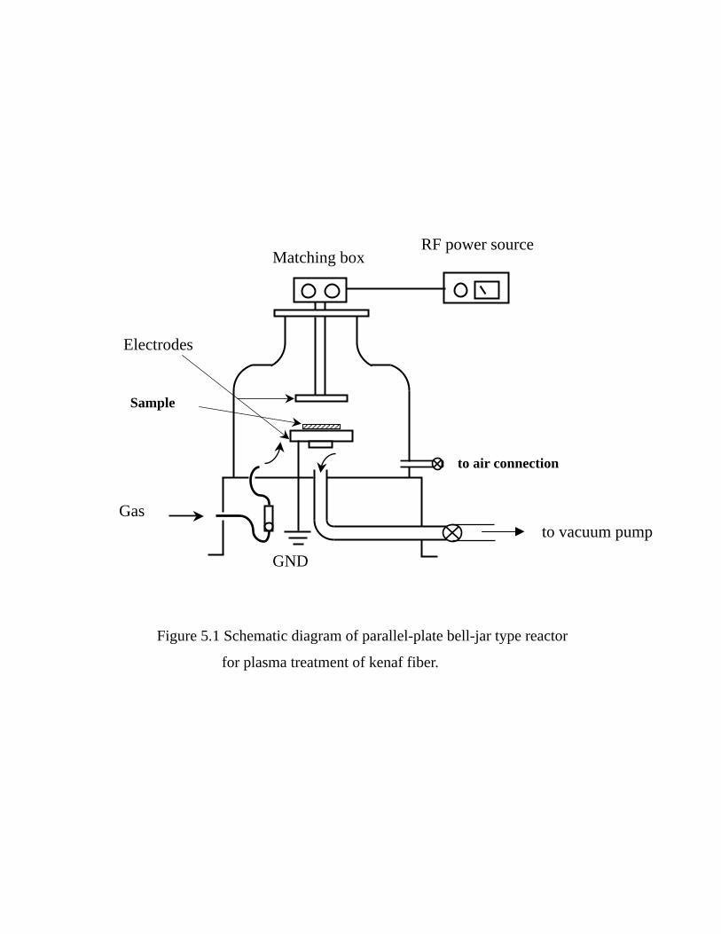
GND
RF power source
to vacuum pump
Sample
Electrodes
Gas
Matching box
to air connection
for plasma treatment of kenaf fiber.
Figure 5.1 Schematic diagram of parallel-plate bell-jar type reactor
86

After the plasma treatment, the fibers were contacted with air atmosphere for 5 min to
form peroxides on the surface. Secondly, graft polymerization was carried out on the
plasma treated kenaf fiber. The fibers containing peroxy groups were placed into the
vessel and then immersed in 2 mL MMA monomer aqueous suspension. After
degassing thoroughly, the graft polymerization was thermally performed at 60 for 5
h. In order to remove any adhered homopolymer, the grafted fibres were extracted
with THF over a night.
Formation of Peroxide
The amount of peroxide formed on kenaf surface after plasma treatment and
subsequent reaction with air atmosphere was determined according to the iodometric
titration with the following procedure:[12]
The plasma treated kenaf were placed in a flask containing solution mixture of
20 mL isopropyl alcohol, 5 mL saturated sodium iodide aqueous solution and 2 mL
glacial acetic acid. The mixed solution was refluxed at 85 for 15 min, and then
cooled to the room temperature. The liberated iodine was then titrated with 0.01 N
standard sodium thiosulfate solution.
Measurements for Characterization
The infrared (IR) spectra of MMA-grafted kenaf fibers were recorded on a
Jasco FT-IR-8000 spectrophotometer, with using their KBr disks.
Scanning electron microscopy (SEM) was used to examine the surface
87

morphology of untreated and grafted fibers. SEM of those fiber samples was observed
using a Jasco JSM-5300 device.
Thermogravimetric analysis was conducted to measure the thermal degradation
of the original and grafted kenaf fiber with using a SEIKO TG/DTA instrument. The
initial sample weight was in the range 4 - 5 mg. TG curves were obtained in the
temperature range from room temperature to 500 under a nitrogen atmosphere with
a heating rate of 20 /min.
XPS analysis was performed using a Perkin Elmer ESCA 5600 instrument.
Unmonochromated Mg Kα radiation (1253.6 eV ) was used from the dual anode X-
ray source for photoelectron excitation. The X-ray source was operated at 400W and
15 kV. The angle between the X-ray source and analyzer was fixed at 45°. The wide
scan (1.6 eV resolution) and high resolution scan (0.25 eV resolution) were carried
out and the C1s spectra were deconvoluted for the analysis using a curve fitting
program of MultiPak Software V.6.1A.
5.3. Results and Discussion
Formation of Peroxide
It is generally known that oxygen containing functional groups can be
introduced onto the surface of plasma-treated polymers in the form of carboxyl,
ketone, hydroxyl and peroxide.[10] Among those groups, the peroxide is the most
possible active species that can initiate graft polymerization in the presence of
monomer. Table 5.1 summarizes the formation of peroxides on kenaf fiber surface
88

after
Table 5.1. Effect of Irradiation Time and Power Applied of Air Plasma on the
Formation of Peroxides on Kenaf Fibers.
Sample
Irradiation time
(s)
RF power
(W)
Amount of peroxide
(meq/100 g sample)
Untreated fiber --- --- 0 Treated fiber 30 5 0.49
60 5 0.69
120 5 1.09
180 5 1.49
300 5 1.39
180 2.5 0.49
180 5 1.49
180 10 1.29
180 15 0.49
180 25 0.20
89

after the irradiation of air plasma and 5 min exposure to air atmosphere as a function
of plasma irradiation time and plasma power. The maximum amount of peroxide has
been obtained when the fiber was irradiated by plasma for 180 s at 5 W of plasma
power that gave a concentration of peroxide of 1.49 meq/100 g sample. It can also be
observed that increasing the plasma power as well as elongating the plasma irradiation
time did not result in more peroxides. The parameters set of 180 s and 5 W were
therefore used for subsequent thermal graft polymerization of MMA onto kenaf fiber.
Plasma-induced Graft Polymerized Sample
The thermal graft polymerization of MMA on plasma-treated kenaf fiber was
carried out at 60 for 5 h. The grafting has been conducted for the different plasma
treatment time, however, the similar results have been obtained in the view that there
was no weight increase in grafted kenaf fiber after extraction with THF. The presence
of grafting therefore was examined by using the following analyses during the
characterization of grafted fiber. The samples for characterizations were taken from
parameter plasma treatment that produces the maximum amount of peroxides for the
effectiveness of the grafting.
FT-IR Spectra
The FT-IR spectra of untreated and grafted kenaf fiber are shown in Figure 5.2.
Figure 5.2.a. shows a typical kenaf spectrum, which carries a broad absorption band
of hydroxyl group around 3400 cm-1, C – H stretching band around 2910 cm-1 and an
90

absorption
C=O
(b)
(a)
4000 3000 2000 1000 400
%T
Wavenumber [cm-1]
Figure 5.2. FT-IR spectra of untreated kenaf fiber (a) and grafted kenaf fiber (b).
91

absorption band around 1100 cm-1 associated to the ether linkage in the pyranoside
ring. It is observed that the FT-IR spectrum characteristic of grafted fiber (Figure
5.2.b.) is similar to that of the untreated one, except an increase in intensity of ester
groups near 1738 cm-1. This additional band indicates the presence of PMMA in the
grafted fiber. Kenaf fiber has shown the peak near 1738 cm-1, which may arise from
the unconjugated carbonyl group in lignin. From the preliminary experiment, it has
been clarified that the lignin content of the used kenaf fiber was 20.6 %, which was
relatively higher than wood or any textile materials. Therefore, grafting of PMMA
onto kenaf was only identified by the increase of this peak intensity.
X-ray Photoelectron Spectroscopy (XPS) Study
XPS is a surface sensitive analysis used to determine the surface atomic
composition and to know the chemical state of the atoms. In this study, XPS
measurements were performed to investigate the changes in chemical composition
and to identify the chemical bonding existing on the surface of untreated and grafted
kenaf fibers. Figure 5.3 shows the high resolution scans of the C1s core spectrum with
their deconvolution peaks for the untreated kenaf fiber (5.3.a) and grafted kenaf
(5.3.b). It can be seen that the C1s core spectrum of untreated kenaf fiber consists of
four different peaks at 284.5 eV for C-H/C-C, at 286.5 eV for C-O, at 288.1 eV
for C=O/O-C-O and at 290 eV for O-C=O. Characteristics of kenaf fiber
surface are mostly indicated by C-O and C=O/O-C-O, among which C-O and
O-C-O are the characteristic of for the pure cellulose.[18,19] However, rather high
92
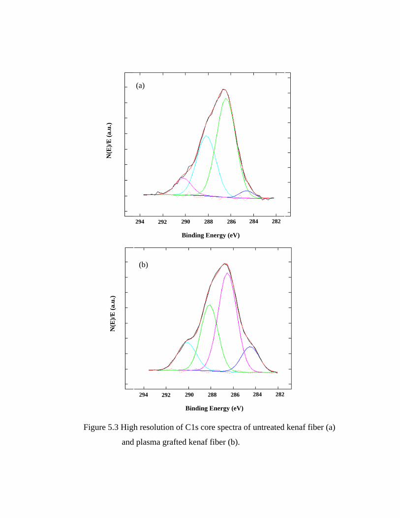
content
282 284
Binding Energy (eV)
294 292 290 288 286
(a)
N(E
)/E (a
.u.)
292 288290 282 284286294
(b)
N(E
)/E (a
.u.)
Binding Energy (eV)
and plasma grafted kenaf fiber (b).
Figure 5.3 High resolution of C1s core spectra of untreated kenaf fiber (a)
93

content of 288.1 eV peak and the lower percentage C-C and O-C=O components
suggest that some hydrocarbon-rich compounds like lignin and some extractive
compounds such as fat or wax are mixed well with cellulose and are present on the
fiber surface. This is plausible since the raw kenaf was only extracted with hot water,
which could not remove some compounds mentioned above from kenaf fiber. Plasma
graft polymerization of PMMA onto kenaf fiber clearly makes differences on the fiber
surface compared to the untreated one, where an increase in peak intensity of C-C
and O-C=O bonds can be observed. The relative chemical bonds concentrations
from C1s core spectra deconvolution of untreated and grafted fibers are summarized
in Table 5.2. Compared to the untreated fiber, an increase in C-C concentration up to
11.6% and a significant increase in O-C=O concentration to 13.2% due to the
incorporation of methylene, methyl and ester groups of PMMA are apparent for the
grafted fiber. Accompanied to those increase are the decreases in C-O and C=O/O
-C-O concentrations. These facts clearly indicate the grafting of PMMA on kenaf
fiber. However, the existence of C=O/O-C-O component of the grafted fiber tells
that the untreated kenaf fiber is still detected by the XPS because it is absent in
PMMA. If the grafted PMMA covers thoroughly the kenaf fiber, the chemical
composition of grafted fiber should be similar to that of PMMA surface. The obtained
result, however, does not agree with it, suggesting that the plasma-induced grafting of
PMMA occurs only to some extent to cover partial surface of kenaf fiber. The surface
area with grafted PMMA can be estimated as 15 % based on the concentrations of
94

thee
Table 5.2. Relative Chemical Components Concentration from Deconvolution of C1s
Core Spectra of Untreated Kenaf Fiber and Grafted Kenaf Fiber.
Sample C-H / C-C C-O C=O / O-C-O O-C=O
Untreated kenaf 3.1 54.9 33.4 8.6
Grafted kenaf 11.6 46.6 28.7 13.2
95

C-H/C-C and C=O/O-C-O components. On the other hands, the calculated
areas based on the C-O and O-C=O concentrations were estimated as 25 % and
40 % respectively, which might be caused by the enrichment of these components on
kenaf fiber through plasma treatment. The XPS study mentioned above leads to a
conclusion that PMMA had been graft polymerized onto kenaf fiber surface, but the
coverage did not occur to all surface of fiber. The SEM measurements were thus
conducted to complement the XPS study.
SEM Micrograph
Surface morphology of untreated and grafted fibers is shown in SEM images depicted
in Figure 5.4. It can be observed from Figure 5.4.a that the untreated kenaf fiber has a
rather smooth surface originally. Several fibrils are bound together by middle lamella
consisting mainly of lignin. The middle lamella was not removed because the
extraction of fiber had been conducted only with hot water. Typical natural fiber
extraction with alkali solution can remove such contaminants, however, sometimes
causing damages to the fiber, which thus decreases the mechanical properties. On the
other hand, the grafted kenaf surface seems to be masked with polymer (Figure 5.4.b).
The PMMA masks can be seen covering the fiber in such a way which lead to the
unsmoothed coverage of the fiber surface. No such damages were found on the
individual fibers. This result has an agreement with preceding results of XPS
measurements. The incomplete coverage of fiber surface could be attributed to the
inhomogeneous interaction between fiber surface and plasma. It is considered that the
96

activation
(a)
(b)
Figure 5.4 SEM images of untreated kenaf fiber (a) and grafted kenaf fiber (b).
97

activation of fiber surface occurred only on the surface facing in a certain direction to
the glow discharge. In addition, the surface activation reaction was thought not to
occur on the underlying region of fiber surface. Another plausible reason is caused by
the roughness and unevenness surface of kenaf (Figure 5.4.a) that cause it variably
susceptible to plasma treatment.[20] Nevertheless, this plasma-induced graft
polymerization has been proved to modify the kenaf fiber surface without altering the
bulk properties.
Thermal Behavior (TG/DTG)
Both of untreated and MMA-grafted kenaf fibers were subjected to
thermogravimetry (TG/DTG) analysis, and the results are utilized to elucidate the
typical changes of their thermal behavior. Figure 5.5 represents the TG and DTG
curves of untreated and grafted kenaf fibers. It can be seen that the overall weight loss
of untreated fiber during thermal degradation could be divided into three different
steps. In the first step, weight loss occurs below 100 with about 7 % of initial
weight, which is attributed to the evaporation of absorbed water from the fibers. In the
second step, the fiber loses its 20 % weight. This is the initial stage of thermal
degradation that occurs around 300, represented by a shoulder in DTG curve. The
last step relating to the major thermal degradation shows a maximum weight loss rate
at 374. Concerning with the grafted fiber, it could be observed that the general
features of the curves are similar to those of the untreated one except the decelerated
weight loss below 100 and the total shift to the right. The former should be the
98

effect
0
0.2
0.4
0.6
0.8
1
1.2
0 100 200 300 400 500 600
Temperature [oC]
Res
idua
l Wei
ght
-0.001
0
0.001
0.002
0.003
0.004
0.005
0.006
0.007
DT
G (d
C/d
t) [ /
sec.
]
Untreated kenaf
Grafted kenaf
Figure 5.5. TG and DTG curves of untreated kenaf fiber (a) and grafted kenaf fiber (b).
99

effect of PMMA layer with low vapor permeability. On the other hand, the latter
shows that the thermal stability of grafted kenaf fiber is higher than untreated kenaf
fiber. This founding is interesting since the PMMA itself decomposed completely at
375, thus the grafting of PMMA onto kenaf should lower its thermal stability. This
phenomenon can be explained that graft polymerization forms a sort of cross linking
with kenaf molecule. The breakage of various linkages by plasma treatment could be
compensated by this new type of crosslink formed simultaneously with grafting,
leading to the enhancement of thermal stability due to lower mobility molecules. This
is also supported by the relatively large amount of the char residue for grafted fiber
compared to the untreated one.
CONCLUSIONS
In this work, plasma-induced graft polymerization of MMA monomer onto
kenaf fiber using air plasma was studied. Peroxy groups were formed and became the
active species to proceed the grafting. The amount of peroxides generated by plasma
treatment and successive reaction with air apparently depended on the plasma
irradiation time and power applied. It was found that that there was no weight increase
in grafted kenaf fiber after extraction with solvent. Some measurements such as FTIR,
XPS, SEM and TG/DTG were used to investigate the changes of surface chemical
composition after grafting. It was clarified that the graft polymerization of MMA onto
kenaf fiber had been occurred on the partial surface of kenaf fiber, and improve the
thermal stability of the fiber.
100

References
1. B. Gupta, J. G. Hilborn, I. Bisson, P. Frey, Journal of Applied Polymer Science, 81,
2993-3001 (2001).
2. Nguyen K. C, N. Saeki, S. Kataoka and S. Yoshikawa, Hyomen Kagaku, 23,
202-208 (2002).
3. Hartwig Hocker, Pure Appl. Chem., 74, 423-427 (2002).
4. I. C. Eromosele, A. Agbo, Journal of Applied Polymer Science, 73, 1751 (1999).
5. Ighodalo C. Eromosele, Solomon S. Bayero, Journal of Applied Polymer Science,
73, 1751 (1999).
6. H.L. Chen and R.S. Porter, J. of Appl. Polym. Sci., 54, 1781-1783 (1994).
7. A.R. Sanadi, D.F. Caulfield, R.E. Jacobson and R.M. Rowell, Ind. Eng. Chem. Res.,
34, 1889-1896 (1995).
8. D. Feng, D.F. Caulfield and A.R. Sanadi, Polymer Composites, 22, 506 (2001).
9. R.M. Rowell, Proceeding of the 18th International Symposium on Material Science:
Polymeric Composites – Expanding the Limit, Roskilde, Denmark, 127 (1997).
10. J. Xu, R. Widyorini, S. Kawai, Journal of Wood Science, 51(4), 415-420 (2005).
11. Kawai S., Sasaki H., Yamauchi H., 1st Wood Mechanics Conference, Lausanne,
503–514 (2001).
12. Ginting S. I., PhD Thesis Department of Chemistry, Gunma University, 2003.
13. M. Suzuki, A. Kishida, H. Iwata and T. Ikada, Macromolecules, 19, 1804 (1986).
14. N. Inagaki, S. Tasaka, Y. Goto, Journal of Applied Polymer Science, 66, 77 (1997).
15. L.M. Matuana, J.J. Balatinecz, R.N.S. Sodhi, C.B. Park, Wood Science and
Technology, 35, 191-201 (2001).
16. G. Beamson and D. Briggs, High resolution XPS of Organic Polymers: the Scienta
ESCA300 database, Wiley, New York, 1992.
17. N. Abidi, Eric Hequet, Journal of Applied Polymer Science, 93, 145-154 (2004).
18. David N.-S. Hon, Journal of Applied Polymer Science, 29 (9), 2777-2784 (1984).
19. Pawel Zadorecki, Tore Rönnhult, Journal of Polymer Science Part A: Polymer
Chemistry, 24 (4), 737-745 (1986).
101

20. Johan Felix, Paul Gatenholm, H. P. Schreiber, Journal of Applied Polymer Science,
51, 285-295 (1994).
21. Y.C. Ma, S. Manolache, M. Sarmadi, F. S. Denes, Starch – Stärke, 56, 47 (2004).
22. D. P. Kamdem, B. Riedl, A. Adnot, S. Kaliaguine, Journal of Applied Polymer
Science, 43 (10), 1901-1912 (1991).
23. Terrence G. Vargo, Joseph A. Gardella Jr., Lawrence Salvati Jr., Journal of
Polymer Science Part A: Polymer Chemistry, 27 (4), 1267-1286 (1989).
24. Chee-Chan Wang, Ging-Ho Hsiue, Journal of Polymer Science Part A: Polymer
Chemistry, 31 (5), 1307-1314 (1993).
25. Ging-Ho Hsiue, Chee-Chan Wang, Journal of Polymer Science Part A: Polymer
Chemistry, 31 (13), 3327-3337 (1993).
26. H.P., L. Viikari, Biotechnology and Bioengineering, 86 (5), 550-557 (2004).
27. M. G. McCord, Y. J. Hwang, Y. Qiu, L. K. Hughes, M. A. Bourham, Journal of
Applied Polymer Science, 88 (8), 2038-2047 (2003).
28. N. Inagaki, S. Tasaka, T. Inoue, J. of Applied Polymer Science, 69, 1179 (1998).
29. G. Canché-Escamilla, G. Rodríguez-Trujillo, P. J. Herrera-Franco, E. Mendizábal,
J. E. Puig, J. of Appl. Polym. Sci., 66 (2), 339-346 (1997).
102