investigation of ahss formability using a customized t-shaped
TRANSCRIPT

Investigation of AHSS Formability Using a
Customized T-Shaped Panel with
ex situ DIC
Advanced Engineering, AK Steel Research & Innovation
Dr. Yu-Wei Wang
05.11.2016

• Goal
• ex situ DIC (Digital Image Correlation)
− A New Approach for Deformation Measurement
• AHSS Formability Study
Deformation Modes and Histories
Edge Cracking and Stretch Bending
• Conclusions
OUTLINE

Goal: A Lab Test that Bridges Standard Tests to Actual Stamping
Actual Manufacturing
Deformation Mode
Forming History
Edge Cracking
Stretch Bending
Lab Standard Material
Characterization

• Adjustable die cavity depth
• Adjustable center pocket
Formability Study – T-Shaped Die Design
R
8
Connected to tableConnected to table

Formability Study Using T-Shaped Panel
(mm)
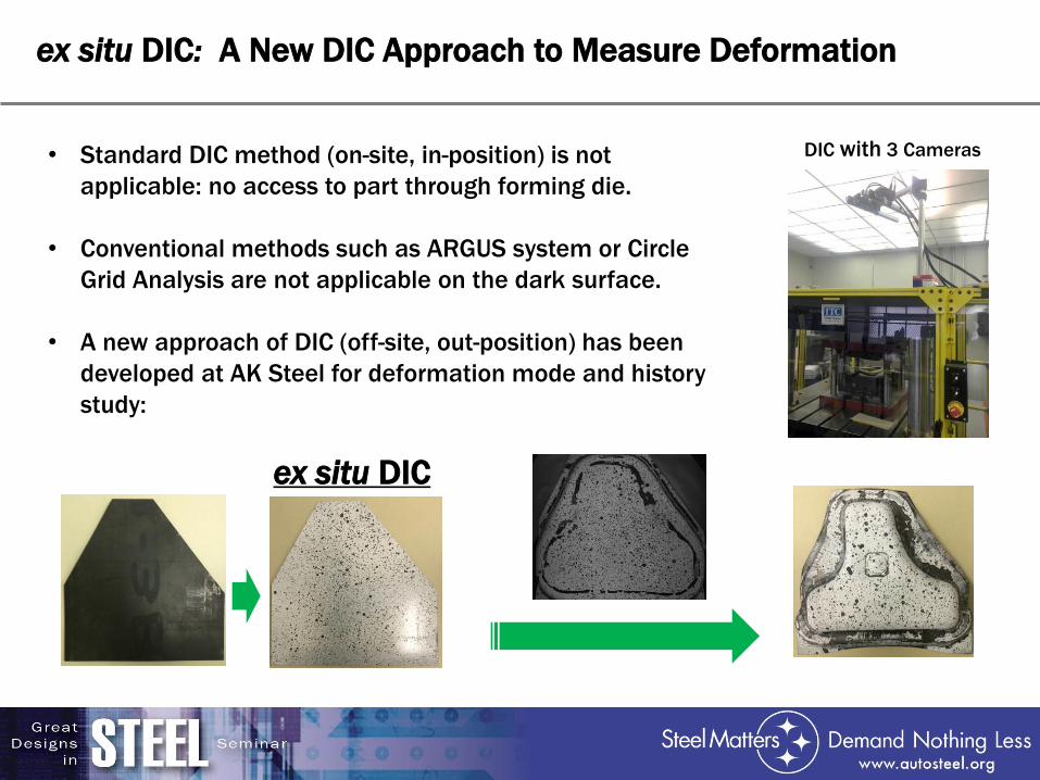
ex situ DIC: A New DIC Approach to Measure Deformation
• Standard DIC method (on-site, in-position) is not
applicable: no access to part through forming die.
• Conventional methods such as ARGUS system or Circle
Grid Analysis are not applicable on the dark surface.
• A new approach of DIC (off-site, out-position) has been
developed at AK Steel for deformation mode and history
study:
ex situ DIC
DIC with 3 Cameras

Major Strain
Minor Strain
AHSS Formability Study - Forming Process

ex situ DIC & Argus
Initial Blanks
With DIC Pattern
(Argus Pattern Covered)
Formed Parts
With DIC Pattern
Formed Parts
with Argus Pattern

Major
Strain
Minor
Strain
Argus*ex situ DIC
Forming evaluation: ex situ DIC vs. Argus vs. FEA
Simulation
*Argus measurement by

1
2
•Material: CR4
•Thickness: 0.7 mm
Thickness Strain
(true)
Thickness
(mm, calculated)
Thickness
(mm, ultrasonic)
Difference
1 -0.08492 0.640558 0.638 0.399%
2 -0.24018 0.531875 0.527 0.917%
ex situ DIC: Validation Using Ultrasonic, Difference Less Than 1%

AHSS Formability Study - Deformation Modes
1
2
3
123
1
2
3
ex situ DIC Reading
1
2
3
123
Simulation Results

The strain history at selected location
FEA (draw depth)
13 mm
10 mm
7 mm
4 mm
Major Strain Minor Strain
1 mm
AHSS Formability Study - Strain Path
13 mm
10 mm
7 mm
4 mm1 mm
Minor True Strain
Ma
jor
Tru
e S
tra
in

ex situ DIC
Reading
Simulation
Results
AHSS Formability Study - Strain Paths of Sections
Strain Unit: 10-3
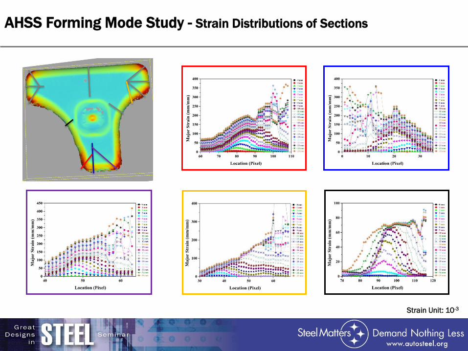
AHSS Forming Mode Study - Strain Distributions of Sections
Strain Unit: 10-3

AHSS Forming Mode Study - Section Strain Paths

AHSS Forming Mode Study - Section Strain Paths

AHSS Forming Mode Study - Section Strain Paths

AHSS Forming Mode Study - Section Strain Paths

AHSS Forming Mode Study - Section Strain Paths

AHSS Forming Mode Study - Section Strain Paths

AHSS Forming Mode Study - Section Strain Paths

Strain Unit: 10-3
AHSS Formability - History

T-Shaped Panel
Test Measurement
ex situ DIC
Microstructure
FEA Modeling
AHSS Formability Study -
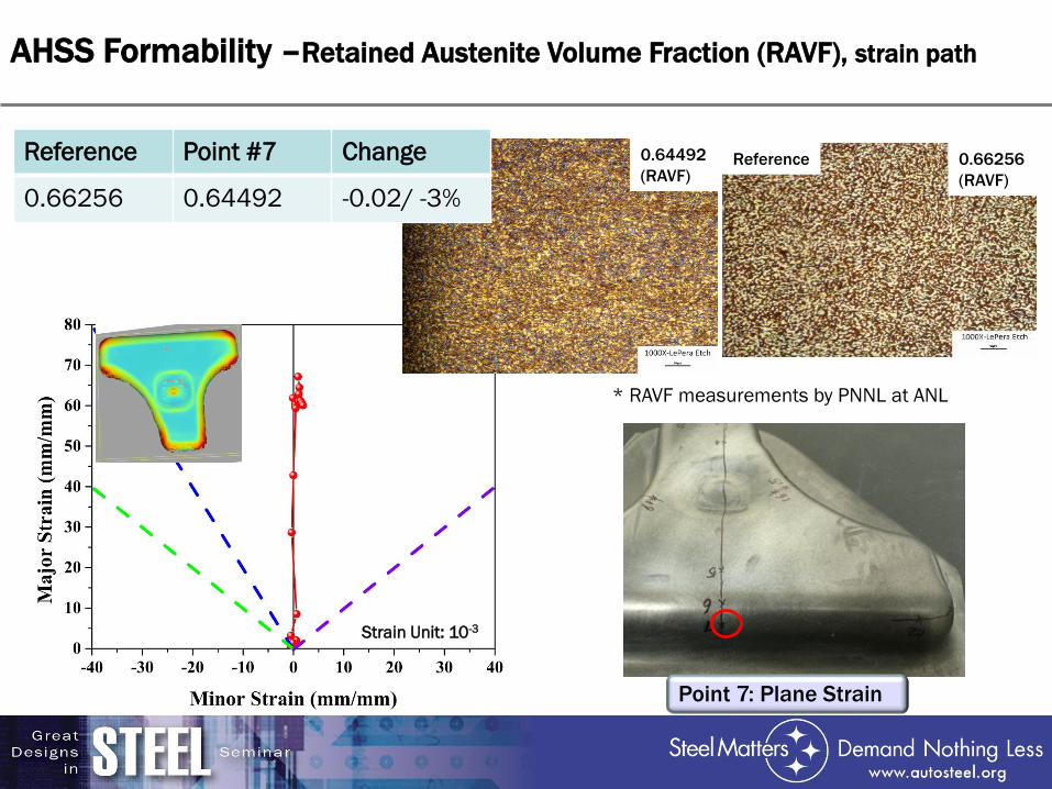
Point 7: Plane Strain
0.64492
(RAVF)Reference 0.66256
(RAVF)
AHSS Formability –Retained Austenite Volume Fraction (RAVF), strain path
Strain Unit: 10-3
* RAVF measurements by PNNL at ANL
Reference Point #7 Change
0.66256 0.64492 -0.02/ -3%

Point 8: Tension-Tension Strain
0.27047
(RAVF)Reference 0.66256
(RAVF)
Strain Unit: 10-3
Reference Point #8 Change
0.66256 0.27047 -0.39 / -60%
* RAVF measurements by PNNL at ANL
AHSS Formability – Microstructure, strain path

Reference 0.66256
(RAVF)
Point 1: Non-Linear Strain Path
0.4156
(RAVF)
Strain Unit: 10-3
Reference Point #1 Change
0.66256 0.4156 -0.25 / -37%
* RAVF measurements by PNNL at ANL
AHSS Formability – Microstructure, strain path

Reference 0.66256
(RAVF)
0.58338
(RAVF)
Point 18: Tension - Compression Strain
Strain Unit: 10-3
Reference Point #18 Change
0.66256 0.58338 -0.08 / -12%
* RAVF measurements by PNNL at ANL
AHSS Formability – Microstructure, strain path

Major Strain
Minor Strain
AHSS Formability - Edge Forming Process
Hole Expansion Ratio:
10.6%
Without hole
With holes
Displacement (mm)

AHSS Formability - Edge Strain
- 0.037, 0.192
Strain Unit: 10-3

AHSS Formability – Edge Strain (Cont’d)
Major Strain Minor Strain
11
44
1
4
RAVF Eff. Strain
Reference 0.66256 -
Pt 4 0.57491(13%) 11%
Pt 1 0.55505(16%) 18%

AHSS Formability - Edge Strain Pattern
ex situ DIC Argus

AHSS Formability - Edge Strain Path
ex situ DIC FEA Simulation

Total Elongation as CriteriaUniform Elongation as Criteria
Edge cracking predicted at 10 mm forming depth
Cracking propagation at 14 mm forming depth
Edge forming at 10 mm forming depth
Edge cracking predicted at 14 mm forming depth
Edge crack initiation predicted for NG980
AHSS Formability - Edge Crack Prediction by FEA

• The NG980 T-Shaped panel with cutouts
was formed.
• Test load-displacement curve shows that
edge cracks initiated at 14 mm forming
depth.
• Both uniform and total elongation of
uniaxial tensile test are used in FEA as
criteria of edge crack prediction.
With total elongation, edge cracking is
predicted to initiate at 14 mm.
With uniform elongation, edge cracking is
predicted to initiated at 10 mm.
edge cracks initiated at
14 mm forming depth
AHSS Formability - Edge Crack Observation in T-Shaped Panel Test

AHSS Formability –Bending
1
2
fracture

CONCLUSIONS
• A T-shaped panel that resembles the top of B-Pillar is selected for
3GAHSS formability investigation. The die is designed by ICME task 3
team and the construction of the die is funded by ICME project.
• ex situ DIC: a new measuring method for deformation is proposed and
used successfully for deformation mode and history of T-shaped panel
forming.
• Together with ex situ DIC, FEA and microstructure evolution, the T-
shaped panel is shown to be effective to study and characterize the
formability of AHSS, including stretch bending and edge cracking.
THANK YOU!

Project Team & Acknowledgements
ICME Task 3 Team Members
(Die Surface) •Chang Du, FCA US LLC
•DJ Zhou, FCA US LLC
•Rick Johnson, FCA US LLC
•Evangelos Liasi, Ford Motor Company
•Yinong Shen, Ford Motor Company
•Feng Ren, Ford Motor Company
•Constantin Chiriac, Ford Motor Company
•Raj Sohmshetty, Ford Motor Company
•Gene Hsiung, General Motors Company
•Tom Stoughton, General Motors Company
•Ken Schmid, General Motors Company
•Lou Hector, General Motors Company
•John Carsley, General Motors Company
•Weiping Sun, Nucor Corporation
•Dean Kanelos, Nucor Corporation
•Hong Yao, ArcelorMittal USA LLC
•Sriram Sadagopan, ArcelorMittal USA LLC
•Eric McCarty, Auto/Steel Partnership
•Feng Zhu, Ak Steel
•Yu-Wei Wang, AK Steel
Project Team Members
•Wei Wu, Ph.D.
•John Panagiotis Makrygiannis
•Feng Zhu, Ph.D.
•Yu-Wei Wang, Ph.D.
Die Structure Design and Argus Measurement by
Ford Motor Company
• Dr. E. Liasi, Y. Shen, L. Huang, G. Kluczynski,
DIC Technical support by Oakland University
• Prof. Lianxiang Yang, Xinfeng Shi, Hao Wang
Phase Volume Measurement by PNNL
• Dr. Xin Sun, Dr. Xiaohua Hu

Q & A
Investigation of AHSS Formability Using a
Customized T-Shaped Panel with
ex situ DIC