investigation -- o f •minuteman d17b computer …
TRANSCRIPT
INVESTIGATION
-- O F
t'" •MINUTEMAN D17B COMPUTER
REUTILIZATION
CHARLES H. BECK
January 1971
vjl.SWoandrae; *tl Uaioesx4it*GSjj
NATIONAL TECHNICALINFORMATION SERVICE
Spmfod.V 25

SIN ESTI GATION F
MINIUTEIM AN D 1 7B COMPUTER
REUT I L I ZAT I ON
by
Charles H. BeckProfessor and Director
SYSTEMS LABORATORY
January 1971
Prepared under- Contract No. F44620-70-C-0050 by
SYSTEMS LABORATORYDepartment of Electrical Engineering
School of Engineering
TULANE UNIVERSITY
for
Directorate of Mathematical and Information Sciences/NMAIR FORCE OFFICE OF SCIENTIFIC RESEARCH
Office of Aerospace Research, United States Air Force1400 Wilson Boulevard
Arlington, Virginia 22209

ABSI'RACT
A large nix-Per of INiS-lOq Inertial Guidance Systems have been declared
excess by the 11CF which contain DlYB digital coiiputers. This report describes
the capabilitics of these computers and many appropriate applications in which
the D17B--a highly reliable and versatile serial-binary minicomputer--can be
beneficially erployed. Typical. areas of application are control, data
acquisition, and on-line comaunications.
A single system design will suffice for the application of several DITB's
to similar tasks. While such modifications are very inexpensive, the required
interfacing must still be developed. This interfacing is the key to flexible
use of these minicomputers; typical I/O devices include: typewriters, tele-
types, flexowriters, magnetic and paper tape units, printer, and card readers.
Despite the difficulties of limited documentation during the early phases of
this investigation and the associated frustration, the D17B is now performing
useful functions in the Systems Laboratory at minimal cost.
-ii
-•.2

TABLE, OF COYENTS
Pace
A13STPACT ii
LaTM OF. FIGURES i
LIST Wi? TAJ3LE-S v
1.0 UT'RCDUCTION 1
2.0 FUNOTIONTAL CHARIACTEISTICS 5
2.1 Central Pro-cessing Unit 5
2.2 1.en ory 14
2.3 Input/Output 20
3.0 PHYSICAL CARUMTE~RISTICIS 24
4.0 OFERATIOHL CHARACTERISTICS 28
5.0 CAPABILIXT Y OF THE D17B CCZ4PUTPR FOR G0HERAL AND)CONTROL WaYMI7JII3 31
6.0 CAPABIL IT OF THE D17B F03 SPIECMA-PURPOSS3 CCNMUTING 3
7.0 D3.TB REMIBILITY8
8.0 IIAIDARE IN1fERACE DEEVELOPI/10-liT 3
9.0 CON"CLUSIONS 43
10.0 ~RWE!iCE 46
BIBIGRAPHJY i48
ELv i

LIE.P CF FIGUR9'S
Page
Sl Minutemian D'7B co:nputer functionr.l blockdiar;ram (conceptual) 6
2 Arithmetic registtur's and rapid-access memory loops' 7
3 Functional location of arithmetic registers andrapid-access meinory loops 9
4 Five phases of DITB instruction execution comparedto sequential operation i1
"5 D17B instruction word for-at 12.
6 Two-address (unflagged) D17B instruction coding 13
7 Three-address (flagged) D17B instruction coding 15
8 Sectional view of the disk-type memory unit 17
9 D17B data word fornat 18
10 Conceptual diagram of the arrangement of memoryloops and registers 19
11 D17B controJ and octal character codes 21
12 D17B data word coding 23
13 Minuteman D17B minicomputer sketch 26
14 DI7B power supplies 27
15 D17B functional data flow diagram 29
16 Flag store instruction sector coding 30
17 Schematic diagram of the Flexowriter-Dl7B interface ho
18 Block diagram of the FlexowTriter to D17B interface 43
19 Block diagram of the D17B to Flexroriter interface 42
iv

:•i I21-T
f it LIM~ Or. TABLP.S
Table Page
13. M4inuteman D17Bl camputer specif'ications 2
I ~2 D)17B instru~ction repvrtoire3
3 DID71 3,osole control siguals 22
Iv.• mm- V
I'_' m

1.0 I•ROW)UCPION
As a result of the current modernization of the I.1inuteran XCIR, force, a
quantity of Inertial Guidance Systems, (Model WS-I0Q) each costing $234,000
have been declare,, excess by the U.1:F. Since over 1,000 of these advanced
computer systems fro:'i the 1CM ./0/Minuteman Missiles are scheduled to be
declared excess, success of this reutilization project can effect a savings
of nearly a quarter of a billion 4ollars.
NS-IOQ systems contain a D17B computer, the associated stable platform,
anO power supplies. Detailed specifications for the D17B computer are given
in Table 1. It is an ex-tremely versatile, multipurpose, serial-binary mini-
computer. The Systems Laboratory has acquired several of these systems, and
the staff has accomplished installation, troubleshooting, checkout, and hard-
ware modifications necessary to make the D17B portions of these systems
completely operational. The high degree of reliability and ruggedness of the
computer are evidenced by the strict requirements of the weapons system. Use
of the D17B is especially appropriate when high reliability is necessary under
extreme environmental conditions such as high shock, acceleration, or vibration
that often preclude the use of other computers. The specific application ,ill
determine the value of any one characteristic.
Although the NS-IOC system was designed for a real-time guidance and
flight control application, the multipurpose computer portion1'2 can be very
useful. for rzny applications once the necessary interface harduare modifi-
cations are implemented since the D17B is comnpletely pro rairar~able. The
instruction repertoire presented in Table 2 contains 59 types of machine
lan:guae instructions ohich provide for efficient, flexible programming.
Ti.e Dl7B con be interfaced to existing7 equipment and it can be shared
among several pieces of laboratory or test equipment. A single system design

YMANUFACTURER: Autonetics, a Division of North Amcrican Rockwell, Inc.SMODEL: Di7B
YFAR: 1962TYPE: Serial, synchronous
*ii- 1UMBER SYSTRi3: Binary, fixed point, 2's conpl.ementLOGIC L.ELS: 0 or False, OV; I or True, -10VDATA WORD LENGTH (bits): 11 or 24 (double precision)INSTRUCTION WORD LIENGT}I (bits): 24MAXfIMUIA 1/O (word s/s): 25,600".N4BRR OF INSITRUOTIONS: 39 types from a it-bit op cole by usinig five bits
'of the operand address field for instructionswhich do not access memory
EXE CUTION TIM:S:Add (us): 78 1/8-Multiply (us): 546 7/8 or 1,015 5/8 (double precision)Divide: (softAware)(Note: Parallel processing such as t,,o slmultaneous &in le precision
operations is permitted .,ithout additional exe:cution time.)CLOCK CAT'I.l'EL: 345.6 ' lzADDRESSING:
Direct addressing of entire memoryTwo-address (unflagged) and three-address (flagged) instructions
WM=IORY:Word Length (bits): 24 plus 5 timingType: Ferrous-oxide-coated U)DRO diskCycle Time (us): 78 1./8 (minimal)Capacity (words): 5,454 or 2,727 (double precision)
fIMJT!OUoUT:Input Lines: 48 digitalOutput Lines: 28 digital
- 12 analog3 pulse
Program: 800 5-bit char/sPHYSICAL CHARACTERISTICS:
Dimensions: 20"high, 29" diam.Power: 28V de at 25ACircuits: DRL and DTL
Doufble copper clad, gold plated, glass fiber iaminate,flexible polyurethane coated circuit boards
SOC1 1;ARE:Minimal delay coding using machine languageModular special-purpose subroutines
"RELIABILITY: 5.5 years VX"BF
Table I. Minutermn Dr(B computer specificatiens.
I
I

52
INume 1-1 c CCde Code Dv-sc ription
00 20, s SAL Split accumulator left shift00 22, - ALS Accumulator left shift00 2hi, 2 SLL Split left word left shift00 26, r SLR Split left word right shift00 50, s SMR Split accumulator right shift00 32, s ARS Accumulator right shift00 .54, s SRL Split right word left shift00 36, s SRR Split right vord right shiftO0 60, s Cox Character output Aoil c, S SCL Split Compare and .ivt10 C, S TMi Transfer on minus20 c, s SM? Split multiply24 c, s MPY Multiply30 c, s SIOI Split miltiply modified34 c, G MPM Multiply modified40 02, s BOC Binary output C4o 10, s BCA Binary output A40 12, s BOB Binary output B40 20, s RSD Reset detector40 22, s HPR Halt and Proceed40 26, s DOX Discrete output A40 30, s VO& Voltage output Ao0 32, s VOB Voltage output B
40 34, s VOC Voltage output C40 itO, s AIR And to accumulator40 ili, s MID4 Minus magnitude40 46, G CCt Complement'0 50, S DIB Discrete input BI0 52, s DIA Discrete input Ah0 60, s HFC Halt fine countdoinho, 7-, s LPR Load phase register44 C, s CIA Clear and Add50 c, s TRA Transfer54 c, s STO Store accumulator60 c, s SAD Split add614 C, s ADD Add70 c, s SSU Split subtract74 c, s SUB Subtract
Table 2. DITB instruction repertoire.
Q9

4
will suffice for the application of a lar6e numbr'x of cC YB's to s5iilar tasks.
It is anticipated that automated systeoms usin,; theý DT1B will materlally reduce
the necessity of constant imnut.). rmnipul..tionz in several applications areas
and the time required to acco,.p).ish the dep,aiAs of an increasingr weok-load.
With auto.natLd equipment nany micre tests can often be perforzwied each day; and
highly-skilled personnel are not required. The key to the successful use of
* the DlTB is the interfacing of various peripheral input/output (I/O) devices
81. 1 as a typew:riter, teletype, flexowriter, paper tape unit, care reader,
printer, and magnetic tape unit. Continued software development is also
needed.
There is an increasing demand for computer systems within DoD, but the
3froducts of this rapidly developing technology have a high price tag. This
project has detionstrated the potential of constructive reinvest!ient of USMF
funds through a unique effort to develop a flexible, reliable miniconputer
system. The D17B can be modified at minimal cost for use in a wide diversity
of applications. It can obviously be reutilized effectively as a dedicated,
on-line, real-time process controller much as in the original airborne inertial
guidance system. MIolifications can be made to include such irportant areas
as data acquisition and analysis, on-line cominiunications, data concentration,
buffer storage, and preprocessing for analysis and conpurtation by a large-
scale computer. The purposes of this report are the follo'ing:
1. Ascertain the capability and applicability of the D17Bcomputer for general anml control compu'nG applications.
2. Investigate the qualifications of the D)17B co-,puter forspecial-p•rpose applications such as on-line digital dataprocessing co.mputer interfacing, and peripheral buffering.
-. Identify all required interface hardware to implement anyrecommended control, general, and special purposeapplication.
4.

I ~ 2.0 FUNCT ONA " °'. ..... -° • , ICS
The DI'0! ec.c.putor in a nultipurpoze, serial-binary minicomputer.
It was de-:1gnc-d pri,'trvly to solve real-timve inertial guidance and flight.
control proble;ns vssociated wlth the 14inuterman I missile. The D17B has the
following general capabilities:
1. Samplinr; and processing of input data in the form of coatrol
signals, diigital data, or pilse-type signals.
2ý Logical decision-rmkinz and performance of arithmetic operations
uwins an instruction repertoire containing 59 types of mpe-hine
language instructions.
A. Tranomiss!on of output date in the forre. of analoS, digital, and
pulse-type signals under program contrel.
The chi-r:.cteristics of the DITB of specific interest in this investigation
will be described. The breakown of these characteristics alon& functional
subdivisions as identified in Figure 1 is not intended to infer that these
elements exist as separate physical entities.
2.1 Central Processiing Unit
Since the DITB is a serial-binary zomputer, simultaneous access to all
"the bits of a memory location is not needed either for instructions or data.
Hence, the ezrithnretie registers need nct be constructed entirely of flip-
flops. Instead, they are in the fo-it of circulating loops in memory as
illustrat•d in Figure 2. The DI7B has four double-rank arithmetic registers
which are accu•,ulator (A), lower uccumulator (L), instruction register (I),
and nunber register (I). Because registers (A), and (L) are addressable,

-A c
fk r
co ~ 4110 04 h0
0 $4 0
0~ 0vz~ od H
04 4
11 04 c
* .40
0.
41 41 04C: 0 u4 0
0. to a)0CD" .-r.9
4*t.li4

C b.
o ~9L
8 96
uC C
:3 aa
AI
040<I
LL.
10*0'CT
-. 0
zz

I
8
they can be used as rapid-acceso storage in addition to performing normal
arithmetic functions. There are two additional non-addressable arithmetic
S* registers which are used without programmer control and one 3-bit pseudo-
index (phase) register. The functional locations of these registers and loops
are illustrated in Figure 3.
The central processing unit (CPU) has I/O access to four rapid-access
memory loops of 1, 4, 8, and 16 vords in addition to the main memory which is
arranged in 21 channels of 328 vords each. Two input buffer loops of 4 words
each provide additional input capability from memory.
Programed data channels cause data transfers into the arithmetic registers.
All mchine functions are processed and interpreted in the CPU. The memory
channel address from bhieh the next instruction is to be taken is determined by
the location counter. When the CPU is ready to accept, another instruction from
memory, the address is specified by the channel address stored in the location
counter and the sector address specified in the previous instruction.
The index register can modify the operand channel address of one of the
imultiply instructions. This register also serves as a selector switch for
choosing one of two pairs of inputs to one of the incremental pulse-type Input
loops and .or selecting one of four external positions for each of the three
D-A analog voltage outputs.
The accumulator holds the results of all arithmetic operations and serves
as an output register for parallel digital data, pulse-type signals, D-A
analoG voltage outputs, and telemetry data. The lower accumulator is involved
in certain arithmetic input, and logical operations. A real-tirm clock is
provided by internal tlmirg, signals derived from the clock channel included in
the disk-type memory.
The instruction repertoire listed in Table 2 contains 39 types of rachine

4 -*
M42
4n J 0
0 Z
C.) -- - zt4J 4
0U 0 C4
4J3
LL. #a
D3.V) au
ZU-4
L- 7-

10
language instructions. Although each type of instruction executed by the D3VB
differs from one another, the kinds of actions performed occur in a common
sequence. This makes it convenient to describe the execution of each instruc-
tion as being accomplished in the follo'-ing five phases vhich are usually
* common to delay-type memories:
1. Instruction search (IS)
Z 2. Instruction read (IR)
3. Operand search (OS)
I4. Operand read (OR)
5. Execute (EX)
Figure 4 shows that the D1TB can perform several of these phases simultaneously
with increased efficiency compared to sequential operation. This figure assumes
minimal delay coding of instructions 'which require an execution time of one
word time. The advantage of this minimized access timing is that, once a
minimal delay coded program is initiated, the effective completion time_ of any
Instruction is equal to the basic execution tire of the instruction. If random
access addressing were used in the D17B, the search operations (IS and OS)
could each require up to 128 word times or one disk revoltion of 10 ms.
Minimal delay coding places the next instruction at a location which will pass
the read head immedia•tely after completion of the current instruction.
5The word size for miniconputers ranges from 8 to 24 bits. Providing for
direct addressing of the entire memory of the D17B as illustrated in Figure 5
by using a 12-bit operand address field is a feature of considerable value.
A typical two-address (unflagged) D1TB instruction as illustrated in Figure 6
has three parts: an op code and two addresses. One address identifies the
operand which fulfills the same function as the address field in a single
address machine, the second is the address mode field S. which is used to

.. ,REPRODUCIBLE
-4-0
CL
".";9.
4"J
•':•...i:..0
"=:9:.":.' 0),a.•
- -- - ~~ - y .-.~-r = .. ,:." a . b..n•
CL
.. -....- . .
-. - -_ n e. -a -: .. a•-
•+ .. +.a• J•'6'•'•' • • +.,• • ... • • •, •+ ,..+...m.., •,•. +,, ,•+• ,..r•.,•................ . ,. .... .... . -.'...•
-s. + .... .... .. ....... ... . . . . .
tM3
a
LL.
ee .a. -- - a-- -- - a - =-.
ej0

12
I.IX X x
Oa-
II
f8 4J
-0-
of-,
PZ
kitI

71-
- I
•-7 •.i~i i!
lo
;Fr
-f a. I
c~ *
fj CA
V4'
9. - - a S

specify the address of the next instruction within the active ire'rioy &hainel.
One bit (P-fla-,) Jh the address mode field periidts the use of two alternate
address modes. If the flag bit in Oi, then an instruction Is interpreted as
a three-address word. A typical three-f&3ress (flawed) imtruction as
illustramted in Figure 7 has four parts: an op codle and three addresses. One
address again identifies the operand; the second is used to specify the chennol
SF in which the present contents of the accumulator are to be stored; the
third is used to specify the address Sp oiP the next instruction within the
next sixteen successive memory -locations in the active channel. A program in
a single aeddress machine is likely to require ,mch more memory than is requiredI by the Du)1B.
k In the tw6-address fornat, the 12 bit operand address is required for
direct addressing of the total Jdiemory, 7 bits are required to specify the
address of the next instruction if any sector ý.tlthin the ective channel is
allowed, one bit is required for tbe- flag, and the , renaining- bits ere
allocated for tbe op code field. This limits the )71B -to 1.6 unique 4-bit
op codes. The 13 instructions thato address the memory use these 4-bit Op
codes and a Vs-bi-prnd addxess fie3;. To of the retaining i-bit op codes• } are used for 'fintrudcioS-s that do not reference uepmory (cntrol, lor-ic, I/O
and shifts). A 5-bit portion of the operana nddress flel. is used as .n
extension of the op cole.
Cons.iderable expensior, of the inctructio, repcrtoire appzc.rs to be
possible. Op code 14 in ncit used, -hence tU V.-lditic. of On' insmbiCtio:U th.At
requires access to memory could be consdldered.. A'l, Tnere n,-e nuthcro ais
unucerl 5-bit op code extension; vhich coubl ba conzr~'ker.6
2.2 Memory
Te delay-type emorn, rrou-ox -catcd disk

WIT5
06cc < 0
<) S,0
0c 0 in!I0 7]0
o$
1%o
- ch
%- CV U.
0(
U, C4CO(4 )'0O t40
CLC
~~4 C. @1f' -S.

illustrated in Fij~ure 8. TWe disk is driven by a 1i00 lIz, 3 0 hysteresis-
synchronous notor. Non-return-to-zero recording is used. The addressuble
iecrial memory capacity is 5,1454 U1-bit (single precision) or 2,727 24-bit
f i•"(double precision) words. The format of these words is sho'vn in Pigure 9.
Man memory is arranged in 21. channels of 128 double precision words each.
These -channels are nuibered in even octal from 00 to 50.
Main memory channels are non-volatile in the event of a power failure or
if the system is shut down. The clock channel contains a permanently recorded
345.6 kxIz sinusoidal signal. Sector inforrpation is also permanently recorded
on another cbannel. The total non-destructive readout memory is designed to
be completely prograamable in conjunction with Ground support equipnent.
_The addressable memory also includes rapid-access loops of 1, 4, 8, und
16 words, two arithmetic registers, and two k-word input buffer loops for
direct data entry. There are two additional non-adilressable arithmnetic
-registers. These rapid-access loops and registers are actually reserved
memory locations as illustrated in Figure 10.
The memory cycle time is 78 1/8 ps if the xemory location is coincident
with a read head. This is the tire required to read one 24-bit serial word
and is defined as one word time. The cycle time for the 1-word registers is
one word time. The worst-case cycle times for the i4, 8, and 16-1;ord loops are
it, 4, and 8 word times respectively. 7he or.nt-cvse cycle time for the rain
memory channels is 128 word times.
Program security or memoxy protect can be maiintained by di. ablin, the
write heads to a portion of the memory to effect read,-only memory. By
enabling these write heads it is possilble t~o pci-forym instruction Vand axerc~ss
modification under progrnm control.

.'1 77 -q-
17
0"
43v
4-0
IM. 2 II
4g
C-r-
oil

1'-18
A-
K K
k. - -3- 3-
3- B-3- 3- 03. 53- 3-3. 3-
3- 3-
a- 3- 13' 3- 0
- - .e.D0
3- 3-
3- 3-
3- z0
3-04'
3- 3. 0a- C 'U
5 0 03- 3- z. 3%
U '-4
V 3- 0- 03- - 3. @3
3-
.9-
A La-3- 3-
3. 3-
3- 3.. a
3. 3-
-q0I: I .� K

19
CL
0
Miff ffff if f-P, Big I0

4 20
2.3 Inp-ut/output
The program, composed of instruction and data vords, is initially punched
on cards of paper tape as illustrated in Figure 11, or it is recorded on
magnetic tape. This program is then entered into rienory. Specific console
initializing an interactive inputs uast be supplied under operator manual
control using push buttons and switches to cause logical synchronization,
-conditioning of logie circuitry, and sequential state transitions betw:een sub-
modes of c wputer operation. The console control inputs initially cause the
Di7 to enter the load/verify mode to prepare for entering the pro:.rv. These
console control inputs are listed in Table ..
Instruction and data characters can be read in durin the load/verify
mode; sequential memory locations are assirv.-d unless a location control,
habracter is present. The domm rate of loading into or comiparing vith the
contents of memory is 100 words/sec or equlvalently 8(X cbaracters/sec since
each 24-bit vord is ccoed of eight octal cbaracters as Illustrated in
Figure 12. Negative data must be represented in two's cwxlement form. Control
habracters read in during the load/verIfy mode condition logle circuitry to
effect appropr•ate cuter operation.
Additional data represented by 48 discrete- lines can be entered under
Sprogram control. One of these discrete lines monitors the detector flip-flop,
DR, wbicb can be set by an external source thereby proaduciA a -logic s1W=l
that Indicates the status of external cquiiproent. This function serves as a
hardvare interrupt. Tf DR is set, certain discrete outputs are inhibited. DR
can be reset under progran control.
Incremental Inputs of +1, -1, end 0 can be added to the respective contents
of eight nemory locations in input loops throu:h direct data entry. These in-
puts are Indeperdent of program control. This capability provides for direct
t÷

21
.-..0-
.~~0 @ 0400 .'
o00 o
J4
0 0 0 0 00 00o00000 0000000000a
0000 -000-0
-- 40
• u.
-ooo o
-oz-
0 0 !-- 0 O0
-• oI -
;+ -I ++ + - .. + ̀ -- + + • ++o o o ~ • +;--+ '+ :•-++ 0D

22
FUNCTION SYMBOL POSITION VOLTAGE LOCATION
CHARACTER 11-15 0 0 V 37-1 to J7-51 -19 v 01-1 to 41-5)
DISCRETE DOC ENABLE -25 V J7-14DISABLE 0 V (J1-23)
FILL FSC NORVIAL 0 V J8-24FILL -19 V
[HALT' ViC' RUm -19 V 37-17HALT 25 V (01-91)
RESET Amc NORM 15 V 37-15RESET -19 V (01-90)
RUe IRK' HALT -19 V 38-16m RuN 25 v
SINGLE' KSK' NORMAL -19 V 38-15I .. Single -25V
TIMING TC _0 0V 38-31 -25v
TIMING' TC' 0 -2 5 V J7-61 __0 V 01-6)
MITE. EN OL48E -26 v J7-16DISABLE -19 V (31-93)
Table 3. D178 console control signals.

23
•IV
0 NI-"-
04
a-a
U-
1
- U
•.I•or IJ6
40
o 0L
IF I
J-. v
•C4
-~

24
diaital integration of vijgi runetiouc, five of L-jlt "A.. tw- V4
each, and one of 48-bits. Variable Increment-type inputs can also be added
to the respecti-we conteiits of memory locations in input loops tbrough direct
data entry. These inputs enter the ý-o;,fputer on two sets of three lines. One
line indicates the sign, and the other tuo mutually exclusive input lines
Indicate increments of one or four. Tie statee-of tle pVasc rr:gister deterrites
Vhich of the two pairs of inputs is selected. A pulsc-trpe input cau be added
to the contents of a specific merory location at ;be nazxrisu rate of 1000
pulses/sec.
4 The variety of output transfers available from the D17,3 under prorrar.
}i control include 3-bit, li-bit, or 8-bit parll-el data channels, discrete logic
signals, pulse type siLnals, 24-bit serial vords, a=3 analoZ signals. Parity
or verify error outputs are also provided as hardwYare-controlled features.
Specific discrete loaic signals are disabled by a harduare interrupt if DIR
is ON.IsW
With these output features, the D17B can output data to an autor-,tie
typevriter, light indicators, audible allrmz, and other ofr-on devices. An
array of lig.t indicators can be used to display datao in various co5ed forri3.
Continuous analog output signals can be nonltored on a ricter, or a perranent
and continuous record can be preserved by usinC a strip chart recorder. 0C•her
perlpheral devices can be used to prepare punched cards, runched pnper tape,
or rzgnetie tape for subsequent data entry into the D17.B or anotber co.put'-
for later processing off-line.
3.0 'PHYSICAL R'DCTM I . ,oeICS
The Inertial Guidance Systens Q(oc~el ThS-lM.) of the 1041 30O'inutersnM WE!.~
)4inaile contains a DrI-B zminIcc---mutcr., the associated stable p-4tform, and

25
power supplies. Tlie D17B, built by Autonetics, a division of North American
Rockwell, occupies 1800 of the chassis structure of the IS-1.(X as shown in
Fignure 13. The power suppl.y section occupies the other half of the chassis
structure torold. The outer body skin which provides the 14S-10Q the capa-
bility of becoming an inteprl part of the missile frame ,ay be unbolted and
removed when the I4S-lO. is to be reutilized for other purposes. Removal of
this body section will have no effect on tie -operation of the D1:B. The
NS-IOQ is located just beneath the payload in the nose cone.
A 28V dc regmlated power supply capable of supplying 25A must be provided
for operation of the computer. Other required voltages are obtained by
convertinog 23%r de into secondary power using solid-state circuitry. The current
drawn from the 28V dc supply will vary from 0 to 25-A with a steady state value
of 19A referred to as full load.
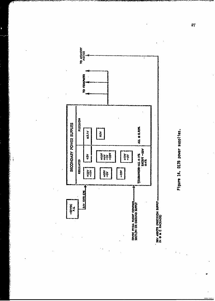
The secondary po.er requirements include 140OHz, 30., and various de
voltages as sbaOn in Figure 14.
The D17B Is 20 in high, 5 in deep, 29 in diameter, and weighs approximately
62 lbs. Components include approxi mtely 1521 transistors, 6282 diodes, u16
capacitors, and 50924 resistors. Theýse conppoents are mounted on doufole copper
clad, engraved, gold plated, glass fiber laminate. There are 74 of these
circuit boards. They have been coated 'itb polyuretbane.
The design of the D1TB placed a premium on reliability since there is no
second chance when an airborne computer controlled mission is executed. 6 '7
Hence, DRL logie was used extensively rather than DTL except where gain was
required. Ext.ensive use vas made of silicon and mesa-gerr."nium semiconductor
devices in this fully solid-state comiputer. A logic level of I or True is
represented by approximnately -1OV, and a 0 or False by approximately OV.

26
C'1
N VJ
MEM4ORY UrNIT
Figure 13. 11IIWT UI~h DIMh r4INCOMIPiJTE SKETCH
27
10
~Cot 06@
U,3 [? 1 n9%
IV

S~28
4.0 cOPI'MTIONAL CHAIRCTERISTCS
The loical power of general-purpose computers is -n~quely co:..on to all,
but speed of execution, nemdory size, cont, reliability, and ease of comu.-
nication (convenience to the user) differ widely. Size and weight limitations,
a high degree of reliability and] strent~th, plus proj~ram requiremrents dictated
a small, slow, serial mderory for the DIlB. However, Muny n. inicomputers haveii ~ less than half the memory of the DIT1B.7A Requirements for real-tine operation
[ i Imply the need for the DITjB to sequentially perform its assig-ned task~s fast
Senough so that all tasks are accomplished during- a given period of tire andI9
yet slow enough to ensure accurate noise-free co:qputntion. 9
In addition to the usual capabilities com-ion to general-purpose computers,
-it can be seen in Figure 15 that the D17B has analog, pulse-type, and serial
output systems. Parallel or multiprocessing such as the simultaneous execution
of two identical single precision add, subtract, or multiply instructions is
another unusual operational capability.
SThe need for store instructions arises frequently because of the need to
preserve intermediate results while so~ne related intervening series of operations
is being performed as in the evaluation of a general polynomial. Simultaneous
execution of a store operation is possible on the D17B coinicident with the
initiation of otber operations without requiring an additional instruction.
The contents of the accmqulator will be stored in the channel specified by the
S2 address as illustrated in Figure 16.
Instruction and adaress rodification give the program the ebility to
branch to alternative sequences of instructions under progr&. control as a
result of calculations in addition to the use of conditional and unconditional
branching instructions. Bit manipulation is also possible if the accumulator
is masked by using the loaical AND instruction.

29
IWLI_ 50
4.
I• I• 00
a -lCo
Fi1Ali
40h

30
rO
Il
I IIle
I E
116
I..Q 0
0-j R
1-5-
0 MUM

Compiler routines hehic have the advantage of reducing prograwing,
effort are not currently available for the D17B. The relative inefficiency
of memory requirement for com'piler produced prosrams cozared vith proerais
writt jin machine langouage rakes the on-line compiler approach questionable
at tV tim a. 10' . The modular approach to the Vriting of special-purpose
sub tines such as rcquired for I/0 operations can result in considerable
san Is in tin: and effort. Certain features such as dedicated I/O registers
.ace the programaer's housekeeping task. The use of rapid-access meory
-loops provides proggrandng versatility and efficiency that help to overcowe
the limited speed of execution and memory size of the Dih.
5.0 CAPABILITY Cl THIE D17B CC.VTPM FOR GERML AU) C¢CURL CO4HWI
Although the Dl1B does not provide all the desirable features of large
general-purpose mchines, It does reseable then functionally and it possesses
a nuyber of similar features. It is a versatile mwtipurpose copater capable
of solving a vide range of problems;f 12 however, it has lr•iited capability,
both in storage capacity w2d ccaputation speed. Unlike the ewpbasIs placed
on efficient processing of many different programs on a Urge general-purpe
amachine, the .wltipurpose DITB Is better suited to dedicated or fixed tasks
that can be served effectively by econcedeal use of the available eaMory and
speed of execution.1'415
Consequently, the Di1B like commercial minicvauoters vith rmell mmwories,
is not vell. suited for general-purpose coiputing vhen coa-xed to a large
computer.1 6 peneral-izwoe conputation in minicoiputer terminology refers
to stW.--alone operation. Some winiconputers are used as stand-alone computers
for scientific ar&P engineering.; use, but mos are used in real-tine applications
such as control, data acquisitionj, coamnalcation cowcentrdtors and processors,
_j*

f 32peripheral controllers and vreDroeessors for large computer systems, display
controllers, buffer memories, blo-medical monitoring, automated testing, auto-
mated Instrumentation and telemetry.17-3
In a practical sense, tUe capability for general computing is determined
by the ability to perform a large variety of calculations. This is determined
basically by the instruction set. Available subroutines simplify the
programming, and asseAlers and compilers simplify the task further. The goal
in providing general-purpose softvare for the D17B is to minimize the amount
of timej, effort, and knovledge required for a user to arrive at a point of use-
ful return for his Investment in the development of the Di7B. Bt, generality
always comes at a price. The D17B Is limited at present to a small number of
real-tfre, special-purpose machine language program'.
the apparent lack of speed Is not such an Important factor when the DITB
Is used as a dedicated control cowpater since much computing speed available
A• :in a large general-purpose computer Is cawwnly lost in system overhead and
i/0* P,3 Furthermre, the 4&-bit and 8--bit parallel output data channels
available on the D17B should prove to be very advantageous in czuunieations
"system that operate on 8-bit ASCII characters, because the overhead operations
o pakng .nd unpacking are mininized. The 24-bit double precision data vord
used on the DiTB appears to have considerable utility for cmputation associated
with these 8-bit codes for character representation vhlch are now becoming
standard. Therefore, the 2g.-bit word of the D17B not only offers more precision
than most inicaquqWars, but It provides for outputting 8-bit suebmultiples.
Computer control applications my include nonitoring and data processin&,
start-up and saut-down procedures, and optlial control. The main attributes
of computer control are coaq tational speed, storuge capability, an4 decision-
waking ability. If sufficient computational speed is available, optimal control

U^ ftni%#Vft%1~ .1 almAw #Pit at^vqnweg, ojnvnywl4 14.- ýv v4 4'mo e~mp g~f w ota~inm4oa Anan
efficient data recording and processing. Decision-making ability provides the
capability for direct digital control.
A direct digital control system must provide a means for measuring the
condition to tb controlled, compare the masured value vith a desired value,
and automratically cause the two values to agree. Data logZing can be performed
as one plase of the control operation. Feed-forward control requires the
solution of equations which represent a predictive matbemstical model. A
control computer can also be used for supervisory functions such as start up
or shutdown operations. Direct digital control requires that each variable
be compared in turn vith the desired values.
Logical decisions and constraints can be employed in couipater control,
and the results of Intermediate calculations and control actions can be recorded
to produce a historical file. The general-purpose capabilities of the D17B
permit the control program to be modified and expanded within the limits of
memory capacity to fit systen growth, new Instruments, or canwging control
policy. The versatility-available vith a computer control system Involving a
general-purpose corquter is an Important consideration.
If the D17B is to be used for control ccuputing applications, it mist be
capable of not only performing control calculations, but a number of other
essential functions also. For examiple, raw Input data are generally subjected
to individual limit checks to detect instrument failures or out-of-normal
conditions, averaged or smoothed to minimize the effects of random variations,
and then recorded or used in calculations. As a typical example of a limit
chock in terms of D17B Instructions. the following could be executed:
1. DIA - data inp.at toA
2. MW - replace the contents of A by the negative of the presentmagnitude of the contunts of A

I - a na the l1mit tolerance to the contents of A
4.. 14I - transfer on minus
These four instructions would accomplish the linit check by perforpdng a
conditional branch. Similar operations could be equally useful for General
or special-purpose coaputins.
It Is appropriate that the D17B be considered for dedicated control
applications Involving control over a single unit or a limited portion of a
process. Such an application imy not only be appropriate considerinrg the
limited memory and execution speed of the DIBh, but the systemi reliability
consideration makes DIB's idealy suited to such tasks. Process-vide control
may require several interconnected D17B's. The real-time aspect of control
applications is compatible vith the current requireioent of zachine langueze
progranling for the D17B.
Considerable benefit can be gained by uing dedicate- co:vputers vbich
decentralize system design and s*Ilplfy software requiremients. The °ajor
edvantanes of using several dedicated control computers are the coplete
iadependence of each unit from failures in other units and the reduced
sopbistication required to program the computations. Dedicated control caniput-
ers make automted start-up a practical consideration.
Since A-D and D-A converters and multiplexers are required for each
cauputer, the use of several dedicated D7B' s could represent too large an
expenditure in conversion equipuent. But, because convr-ion and other sub-
Ssystem costs have been reduced considerably, the use of several dedicated
cauPuters appeasa to be feasible. Delays caused by breal-down can be avoided
by udinG a dedicated on-line rachine, and there is no question ahout progran
security.
As new instruments are added mid as knowledge of a process increases,
F'

bctter control policies can be developed. Hence, control pronomns are
constantly in need of chal.•,,. Also, the characteristics of the process will
often Change as Its operation is improved througb eoajputer control. Because
of these factors, th.e prornrarmble feature of the D17B is extremely desirable
as well as its flexible I/0 capabilities. which can accotO.vate- a -variety of
control devices. The DI'(B can provide digital, pulse-type, and analog output
signals under procrma control for manipulating process variables. This
flexible I/O capability provides for efficient interaction between the DI17B
and the devices being controlled.

6.0 CA~PABILITY C*' WE DW.B Fa SPFCIAL-PUflPOSn- CaCI.PUINiIG
Certain special-purpose applications such as on-line di-ital data
processing, coaputer interfacing, peripheral bufferina, and data nonitorinz
require very little CPU sophistication, li.•ited arithrietic capability, and
perhaps low-speed performance comp-tible with the D17B specifications. The
dominant requirement of many special-purpose coTputer applications relates to
the I/O architecture as is the case for control applications. Section 2.3
I describes the I/O capability of the DlTB. The importance of I/O channels is
particularly significant where data is being transrdtted continuously between
the coaputer and peripheral devices.
On-line digital data processina often requires that analoj infor,'ation be
converted to digital form using an A-D converter. ith the 21 4-bit double
precision word of the D17B, the output from two 12-1bit A-D converters can be
inputted simultaneously under proýrwa control. The required speed of I/0
- transfers and airthrietic for special-purpose- data acquisition can be icuch
slower than for control applications because real-time analysis and control
* response cormands are not necessary. Hence, the D17B with functional capa-
bilities as described in Section 2.0 is flexible enough to be used in these
special-purpose areas formerly requiring special-purpose computers. As
requirements clhange, the D17B can easily be re-proarm-ned. In such fields as
uredical research, blological studies, and experitmntel physics, the D3.7B can
be pro-jrmwrd to control the monitorinG, :.easuring, and recording of a vperiety
of quantities such as pressures, flow rates, EKG, and heart rate. Autamtion of
chemical laboratory instruments such as chro;nton-.phs, spcetrorieters, end
AutoAnAyzers using the DlTB also eppears feasible. Calculation of desired
paraneters, recording of results, and graphic display are appropriate ap-
plications armos for this computer. Simultaneous measurements of several

'7
quantities are pos:;iblt! through the use of saImple-andL-hold devices, a multi-
plexer, and an A-D converter.
A fleyible, rcllble, mobile data monitorinrt systen can be developed using
the Dl(B coaiputer with interface to any of the following: operational
mplifiers, scople-andl-hold dcvices, multiplexers., analog-to-digital converters,
digitaI voltrieters, counters, CtVP displays, plotters: progra~mnble signal
generators andl power supplies, transducers, and sensors. This co•bination vill
provide for the automiatic testing of electronics components, IC, logic cards,
complete logic asseimiblies, and other devices and circuits. Programmeed trans-
ducer testinj ani high-quality date- collection of signal characteristics such
as amplitude, current, and phase iwhich can be acco,,plished at high speeds have
significant advantacges over manual methods. These techniques are also
applicable to non-destructive testing as employed in the inventory of aircraft
parts based on the characteristics of the steel as represented by the electrical
output of spectro-Yoter-type instrwmnts.
On-line coi =nication is also an importert applications area to be con-
sidered for the 117B. A data concentration buffer storage system for teletype
and other lov s eed I/O devices can be developed. Programed rwItiplexing of
parallel information for serial transrission over a narrow-band c(,uwnication
channel is possible sitce the D3.7B can provide for changing the scan rate.
Preprocessing for analysis and computation by a large-scale computer will also
be an a•propriate consideration.
- ---~ -- - - - -7 -- -
I
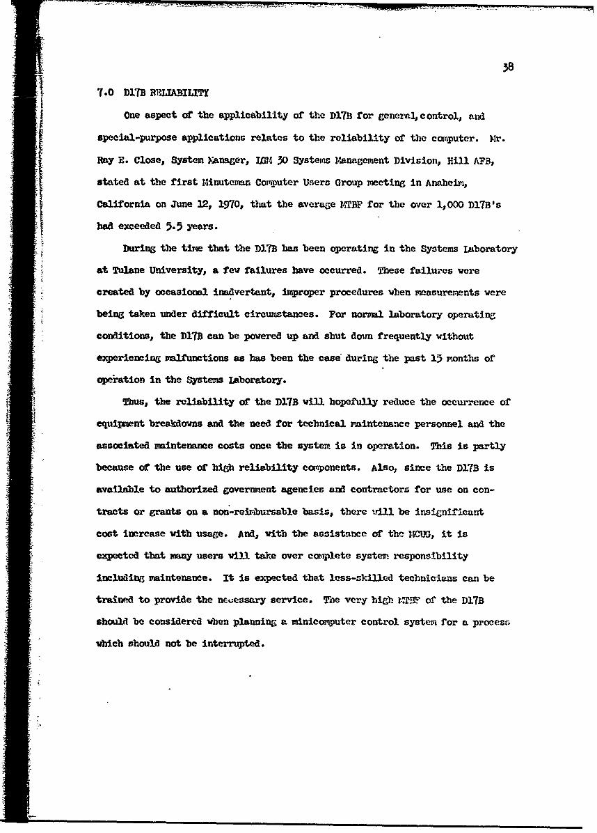
7.0 D17B RIEMABILITY
One aspect of the applicability of the D17B for generaJcontrol, and
special-purpose applications relates to the reliability of the computer. Mr.
Ray E. Close, System YAnager, W.1 30 Systeims Mane.gcment Division, Hill AFB,
stated at the first Minuteman Corp.uter Users Group meeting in Anaheimi,
California on June 12, 1970, that the average ?4TBF for the over 1,000 D17B's
bad exceeded 5.5 years.
During the time that the D17B has been operating in the Systems Laboratory
at Tulane University, a few failures have occurred. These failures were
created by occasional inadvertant, improper procedures when Measurements were
being taken under difficult circumstances. For normal laboratory operating
conditions,. the D17B can be powered up and shut down frequently without
experiencing malfunctions as has been the case during the past 15 months of
operation in the Systems Laboratory.
Thus, the reliability of the D17Bwill hopefully reduce the occurrence of
equipment breakdovns and the need for technical maintenance personnel and the
associated maintenance costs once the system is in operation. This is partly
because of the use of high reliability components. AlSo, since the D17B is
available to authorized government agencies and contractors for use on con-
tracts or grants on a non-reimbursable basis, there ",ill be insignificant
cost increase with usage. And, with the assistance of the 14.0WU, it is
expected that many users will take over comqplete system, responsibility
including maintenance. It is expected that less-skilled technicians can be
trained to provide the nejessary service. The very higbh i.2,9 of the D17B
should be considered when planning a minicomputer control system for a procesn.
which should not be interrupted.

'98.0 HAW•)W'AlR•I',[ ',RtDA', DV1,LOPMR.NT
The hordware thua has been -3eveloped during this investigation consists
of the I/o Interface required to connect the D17B to an electric typewriter
and a paper tape reader/punch. The peripheral device is a Friden Plexowriter,
Model SPD. This device is cmronly avaiable as government excess ADP equip-
ment. Figure 17 is a schematic of the interconnections between the Flexowriter
and the P17B. Inteftree design requires electronic and functional consid-
erations.
Figure 18 is a block diagram of the electronic circuits required for
conditioning the input signals to the D17B from the Flexowriter. These circuits
are required for the purposes of suppressing noise, changing voltage levels,
inverting the signals from positive to negative logic, shortening the pulses,
delaying the timing pulse, and generating the complement. Figure 19 is a
block diagLram of the electronic circuits required for conditioning the input
sigrnls to the Flexowriter from the D17B. These circuits are required for
stretchina or storing the information plses, delaying the timing pulse,
changing voltage levels, and inverting the signals from negative to positive
logic.
The following should be considered in planning for a D17B system.
1. Shipping for D1TB and I/0 devices, available through DSN.
2. Interfaces for connecting peripheral I/O devices to the DI7B.'
3. 28V de power supply rated at 25A.
St. Air duct and circulating blower (air at 750 for less).
5. Operator control panel."
0. Fngincering effort and labor to install and check out the D17B."
7. Soft-ware developvi-nt, trouble-shooting, and maintenance.
""Available through the .llinuteman Computer Users Group.

40
A. "OCnW lr r OD E mn I.n rlI lCATIOI4:MOD i FiED
FLEXOWRITER OUTPUTS FLEXOW'RITER OUTPUTSKEY FUNCTION 11-12 13 14 15 I1 12 13 14 15
SPACE 0 0 0 0 0 1 0 0 0 0 1
I LOCATION 121 0 1 1 1 0 0 1 1
ENTER 2 1 0 1.1 1 0 1 1 0
FILL 0 0 0 0 1 0 1 0 1 1
COMPUTE 0 0 0 0 00111
VERIFY I 1 0 1 1 11 0 1 0
CLEAR 1 I 1 0 0 0 1 1 1 0
HALT 1 0 0 0 0 0 0 0 1 0
8, INTERFACE:
CHANGE VOLTAGE LEVELS FROM OV/90V TO OV/-25VAND/OR FROM OVi-1OV TO OV/90V.
PIN 1 1117-1 11PIN 2 ,,7-2 12FLEXORITER PIN:3 INTERFACE 0'..3,L D17
2 PIN 4 14MODEL SPD PIN 5 15 UNIT _47-5,13 COMPUTER
PIN 9 TC J7-6,TCPIN 16 GRD. .__
P1 PIN I SCn_ J6-19S° P N 2 SC6-0
PIN 3 SCx - INTERFACE J6-21
PIN 4 SCLo.. J6-22.. . 1i 50 S C50 I._ UNIT_ J6-23
LLPIN-27 SCT -J6-2
Figure 17. Schematic diagram of the Flexcoiriter-D17B interface.

I NTERFACE
(A) IfWFOIW.ATION SICGNALS
11 TO I5 SCHMITT
"INVERTERSTRIGGER
CIRCUITS IS 0
i•901 "- 25
?0
tB] TIMI4HG PULSE
0SCHMi!TT
-25
INVERTER TRIGGER
CIRCUIT
25
ONESIIOT ONESHOT
CIRCUIT CIRCUIT INVERTER 25S~0(-- 1] [2]
Figure 18. Block diagram of the Flexowriter to D178 interface.

44
-IL-I-
cc t
IPA
4a
ILU au'I-
Im0 0
U.U
400
Minicc.ratcrs are designed primarily for scientific compting such as
control, data acquisition, comiunications, and other dedicated applications,
but they have the sa.me basic hardware components as large-scale computers.
Although the D17B was designed specifically for use with the Minuteman missile,
it exhibits characteristics similar to cowercial minicomputers. The cost of
developing, a Di1B systen, is low enough and it is flexdble enough so that it
can be used in many new applications areas.
Because of the availability of a large number of Dil7 computers, the
potential exists for spreadint the development cost over a large number of
computers. There is need for furtler sortware development, further peripheral
I/0 develolvent, and for the development of low-cost peripherals.
Since there is an Inherent trade-off between equipment cost and programing
effort, it will be desirable to share standard subrouiines developed by various
users. The I/0 capability of the Di1B has been found to be particularly suited
to real-timi applications such as control, data acquisition, sad other speclal-
purpose uses. The ease with hleh any general ne.ory location can be directly
addressed is a desirable feature. The lack of speed inherent in a serial
ecmuter is partially compensated by the rsultiprocessing capability.
For general or stand-alone computing applications, the folloaing
capabilities are required.
1. Computer rust be program-able and capable of uodifyingthe program as a result of calculations.
2. Instruction repertoire must be adequate to pe.rform thedesired variety of calculations.
3. memory rost provide for atre of datap programinstructions, and the results of calculations.
'. A suitable means must be provided for outputtin,recording, wnA displayinZ the results of calculations.

The D173 bas been proarammed to perform the calculations required for
navigation, guidance, and control purposes such as numerical integration
using Simpson's rule and sine-cosine power series. It has been proseramwd
Le, in the Systems Laboratory for such additional computations as square root,
reciprocal, lo.aritbn, and n-th root. Ther--fore, it is concluded that the
D17B meets the requireveut of being prograi•able.
In the missile guidance application., the write beads for the main m•emry
were disabled to provide for memory protect. The necessary logic signals have
been determined so that these write beads can be enabled. This permits the
l flexibility of instruction and address modification under program control.
Many inicamputers offer bardvare iwltiply and divide as options at
l extra cost. Although the D17B has four hardware multiply instructions, the
,us 1division operation bas been omitted for the purpose of decreasing size and
ýed -- weight. If only a few constants are to be used as divisors, the reciprocals
4- can be preca_-ulated and used In place of the constants. Division by a factor
- -of two can be accoplisbed by right shifting the data in the accumulator. If
the exact value or the data that are to be used as divisors are not known a
liorl, but the range In know, then a subroutine for the reciprocal can be
written. If A Is the data word that is to be used as a divisor, then the
desired reciprocal A can be obtained by an iterative computation involvinG
two miltiplications and one iubtraction per iteration. Multiplication by
* • the ecliprocal can then replace the division operation to complete the
ce•alement of arithmetic operations that are norAly available. •he DI1h
hes both an unconditional transfer instruction and a transfer on minuz
4 instruction. This latter instruction can be combined with other Instruetions
to provide other types of transfers. Thus, allowing for the use of certainf subroutinesb, the Instruction repertoire Is adequate to perto.p a variety of
C,

S-- •= • • /7 • •u • •- -:
"45
calculations. Subroutines must obviously be used for such calculations as
square root, lotaritzfi, sine-cosine, and others.
Unless the D17B is riodified by increasing the memory capacity or used as
a tandem interconnection of several units, then the application to general
computin wdill be limited to those tasks for which 2,727 words of 24-bits or
5 words of 11-bits are adeqtute. I/0 interface capability mest be
provided by the user. The Systems Laboratory has developed a console control
panel for manual program input. A flexowriter has been interfaced to provide
typewriter keyboard and paper tape input as well as printed output or punched
paper tape. A CRT display scope is also available for output monitoring.
In addition to capabilities required for general computing applications,
control comuting applications require a flexible I/O structure to accomodate
a variety of devices. As described in Section 2.3, the I/O capability of the
D17B is extremely versatile.
For real-time control applications, the DMT rmst be able to accept and
process input data sufficiently fast that the results of this processing can
be used to influence and control the appropriate variables. The DITB was
designed to accomplish real-time coMutation as required for missile ."uidance;
however, the bandwidth of the particular application will dictate the speed
requirement. The D17B performed real-time ccwiunication viha external devices
such as the velocity meters, accelerometers, end D-A converters to obtain data
and issue cemr-nds necessary for navigation, guidan•e, telemetry, and control
functions.
As indicated in the specifications given in Table 1, the DiTB has a
maxiMUri i/0 data rate of 25, &00 words per second. Direct data entry is also
provided. Hence, within the lUits of its carabilities the Dl1B appears to
be very appropriatc for a variety of control and special-purpose applications.

3.0.0 RWMECF-S
I. D. 0. lBaeehlcr,, "State of the art of aerospace digital cam~puterso 1962-1.967,," Cotr~uter Group News, vol. 2,, pp. 1-12,. January 1968.
*2. A. S. Buchman., "Aerospace computers, " Adva~nces in Coiqputers, vol. 9,PP. 239-284, 1968.
3. 0. Iapidus, *A look at minicomputer applications,," Control Engineering,,
p.82-91,. November 1969.
WI . H. JWol I'I~wasion of the minico-,iputers, " Automation,. August 1969.
5. A ptein and D. Bcaseli "Mncmptr are made of this,," Cor!puterDecisionss pp. 10-22,, August 1970.
6. B. , 1oper end L.. D). Ahdabl, "Trends in nerospace coxm. uters, " Data m-tion,4Qi. -1p. 22-26,, November 1967.
7. J. Coben, 'Mini-co,-uiaf," No randatta, vol. 2., N~o. 8, 196-n.
8. R. T. Oflivier., "A tecbnique hor selecting small computers, " Datama~ion..Voa. 16,~ jp. li:41445, tdiuary 1910b.'
9. D. J. Th1i0i and Lý. 04 1cobbs, '1d4~i-eompi4ters fpr real-time applications,"
10. R. L. g~o pe-kj 11%he Miui~s utqrj I fpfograx-ring, eballenge, " P-roc. APIIPSp a T 'Ia.
* 1II. R. 'W. Sfper ei _ij'j~1cmue ~tae"I~~Cmpter Group
-!ý! v4- 3J JU3lr/Auau t i970.
IL .- D.sT vo..;12.B~ )~1~e~sto "U2~can YOU flb jifi4i a rainicomputter, " Industrial
it 3. J. Lowensteinj "The riinicoixbUuter: The zqachine- with an endless fu.txre,-de~oi voi~ l8f. no'. 9, Aprdi 970.
R1 . . RBinder, "The Input/output architecture of ninicoruters, " Dateriation,vol, 16,, pp. 119-121,p MaY 1970.
1,5. U. UI. Bbberts# JMiniccm~pter arcliltecture," M CoptrGroup Vews,,vol. 3I pp. 5-9., July/A.usust WOT.
16. F. Gruenberger., "Are small free-stawon"ii corp-tters )bere to stay-."Datamati-oh, vol. 12,, pp. 67-E'A, iiriý 1j966.
17. 'R Abrahaxisont '14iniccarpiters-for-large scale process control," flataration,vol. 16,, pp. 12-2,Februt~ry 1970.
i.R. E.Andersonf, 'TDedicatted comiputers for instrumient control' March 15,1968, Contract W-7h05-eng-1 i8 (McR-,7o638).

47
19. R. F. Anderson ana J. W. Frazer, "Computer control in chemistry at thelawrence radlntion laboratory," J. Corip. Phys. vol. 2, p. 4811, 1968.
20. D.. A . Iabroff, "Avoid pitfalls in computerized testing," ElectronicDesign, vol. 17, pp. 196-201, AuguSt 1969.
21. S. J. htiley, "On-line computer users polled, " Control Engineering,pp. 86-94i, January 1969.
22. HI. Cole, "CWnputer-operated X-ray laboratory equipment,' IBM Journal ofResearch anl Development, vol. 13, pp. 5-1:4, JanuaryT196.
23. R. A. Fdwards and B. II. Polishook, "Laboratory automation based (IAB)
systems, " Instrument Society of America, 23rd Annual Conference,New York, October 23-31-19o8.
24. J. W. Frazer, -)igital control computers," Anal. Chem. vol 40, p. 26A,1968, and "Instruments and computers," Science and Tech., p. #1,July 1968.
25. J. W. Frazer, "Instruments and computers," Science and Technology, no. 79,p. 41, July 1968.
26. W. D. Gwinn, et al, "On-line control, data collection, and reduction for
chemical experinents," J. Cocmp. Phys. vol 2, p. 439, 1968.
27. T. A. Jones, "On-line computers: A survey of techniques amd conceptsapplied to low-energy nuclear research," IMEE Trans. Mecl. Sci,
p. 576, February 1967.
28. a. N. Kessler, "Where ES and MD link up to prolong life," ElectronicDesign, vol. 18, no. 4, pp. 24-28, February 1970.
29. M. H. Mueller, L. Heaton, and L. Aniot, "A computer controlled experiment,"
Research and Develop'.ent, p. 34, August 1968.
30. R. P. Noonan, '.hat kind of computer for your plant," Chemical Engineering,
pp. 11-3-116, June 1969.
31. R. E. Penczer, "Autoyation in data acquisition," American Laboratory,April 1969.
32. R. J. Spinrad, "Automation In the laboratory," Sclence, vol. 158, P. 55,
33. T. M. Stout, "Process control," Dattamton, vol. 12, pp. 22-27, February
1966.
34. 11. F. Youvn, 'Distr-buted co•mater systems," Automation , October 1969.
35. F. Coury, "A systers approach to ninicanputer I/O," Proc. AFI 1970 SJC,1970.
36. E.. Pollani, '1nl4icomputer I/O and peripherals," IEEE Computer Group News,
vol. 3, pp. 10-14, July/August 1970.

B I B 1.WR AFF~
1. Baron,, R. C. ana A. T. Piccirilit, 1A,-it I LO-ic War'Ci~'r pr~inI Vcm Graw-iiifl1967.
2. Bartee, T. C., Digital CompuUer Fnm't1j 1W'.iJ 96
3. Braun., F.. L., Di~gitaJ. Ce'n'putýer Dc3ir?:j Acn!TrienCPri 95
- i&. GearC. 'j.., Co.-iuter Organi~tvtion ta!2t Prpivip:rin-, cr'ri. 99
5. Grabbe, -!. M4. etL- al,, !nbo&ok of Antrto cfl.o;n ~ t&~e~~CnrlWiley 1-959. a
6. Harris, J. NT.,, et al., Digital TimnsistCvi 0i*utg~ie 96
7. Head., R.., Reall Time Business Sys'te-msj H!oli, Rinehart emi '1rzston I1904L.
8. Hill, F. J. and. G. R. Peterson., I~t~ro&!uet4Pf n ýp $Aitch1Ter 4
Logic Design. ' Wiley 1968.
9. Huskey, H. D. and G. A. Korn, Cm~p~ter Fanzbo0!-,, !cGrwi -Hill. 19611.
10. Levin., D., Logical Desicn of S i-tebiri Cird-it~p,x A,:,--rice r --1svi cr, 19 69.
11. McCluskey, 3. J., introduction to itbe Theory of Sitch-Aig, C;Lycq'jt§; !.Ic -
Gray-Hil 19065.
12. M4aley,, G. A. and Z. Barle-ý, Tbe Logic DJesign off Trpmgi~qtor Dijgjjj4 Coiu tcrr s,Prentice Rall 196ý3.
13. Y~aley., G. A. aid '37. J. Dkiko, M'odern Digital. C..r.tiatrsj Pren'tIce E-a11 J1964,
* 1. '~.3ate~,F.- !4. end C. G. Enkec. Digeitall Fiect~ronic5 for Scierutists, 7.
A. BeenjaPirn, 1969.
15. !MAA-us.. J., Sourcbo~kof Tlcronic Circuits Icri~iJ 9'6.
*16. Martin, J. T., Design of !eal-Tin-- Corgae ~jtplrc'rtice ITIE3, 19*7.
17. M~artin, J. T.., Pr mir-iring Real-T2ime Ccmzet' z SPt rent-tice fiall. 196-5.
-- 18. Mi11mn, J. ane R. Taub, PusDgtlaaSici',%vreform, !*cCtraw-
Bini 1,,09'..
19. Rothstein, Guidle to the Design of t1-~-~ Ss~ Johi *'iley urOi Sons, V1970.
1 120. Walston, J. A. and J. R. M4iller, Transistor Mreuit'~il IcGrav,--Eili 1963.
21. WoodP. ". S.tcbing Theory., !' .c~rav-!!i3 1968.
-TXlncludes an extensive bibliacrapby.