investigate the behavior of 3d textiles … a 0.75 volume fraction of the micro steel and...
TRANSCRIPT

VOL. 13, NO. 4, FEBRUARY 2018 ISSN 1819-6608
ARPN Journal of Engineering and Applied Sciences ©2006-2018 Asian Research Publishing Network (ARPN). All rights reserved.
www.arpnjournals.com
1188
INVESTIGATE THE BEHAVIOR OF 3D TEXTILES FIBER REINFORCED
CEMENTITIOUS COMPOSITES PLATES UNDER IMPACT LOAD
Nadia Moneem
1, Ikbal N. Gorgis
2 and Waleed A. Abbas
2
1Civil Department of Najaf Technical Institute at the Furat Al-Awsat Technical University, Iraq 2Building and Construction Engineering Department, University of Technology, Baghdad, Iraq
E-Mail: [email protected]
ABSTRACT
We have proposed a new textile reinforcement which was made from non-corrosive material (smart material: such
as steel and glass). That will be effectively reduce the required concrete material, this technique which is called the Textile
Reinforced Concrete (TRC). This paper presents a plate specimen with dimension of (500x500x400 mm), to demonstrate
the effectiveness of our material we have tested under an impact load during 28 to 90 days with two different conditions
simply support and fixed, respectively. Cement mortar with 60 MPa, 7 cm cube shape compressive strength for 28 days has
been designed for the casting process of the plate. The reference plate (has 22 sub plates) which is divided into four
categories were casted essentially with 3D glass fabric, all these groups have three different thickness (6,10, and 15 mm)
indeed a 0.75 volume fraction of the micro steel and ferrocement that is known as mesh chicken wire layers. The
simulation and the experimental results demonstrate that, the steel fibre gave higher quality results than the 3D glass fabric
and mesh chicken wire, indeed we have proven that the 3D glass fabric with 6 mm gave higher number of blows than the
other thicknesses.
Keywords: 3D textiles, impact test, self compact mortars, textile reinforced concrete.
1. INTRODUCTION Structural elements are commonly subjected to a
wide variety of static and dynamic loads. One of the major
categories of dynamic load is impulsive or shock loads.
These may be caused by missile impact, blast loads on
structures, aircraft crashing against a structure, etc [1].
Impact strength is of importance when concrete is
subjected to a repeated falling object, as in pile driving, or
a single impact of a large mass at a high velocity. The
principal criterion is the ability of a specimen to withstand
repeated blows and to absorb energy. In general, the
impact strength of concrete increases with an increase in
compressive strength, but the higher the static compressive
strength of the concrete the lower the energy absorbed per
blow before cracking [2].
The capability to absorb energy, often called
‘toughness’, is of importance in actual service conditions
of mesh reinforced composites, when they may be
subjected to static, dynamic and fatigue loads. Toughness
evaluated under impact loads is the impact strength.
Impact resistance of any reinforced composite can be
measured by using many different test methods, which can
be broadly grouped into the following categories.
a) Drop weight single or repeated impact test,
b) Constant strain rate test,
c) Weighted pendulum charpy type impact test,
d) Explosion- impact test,
e) Projectile impact test,
f) Instrumented pendulum impact test,
g) Split Hopkinson bar test [3].
Numerous methods have been reported to
estimate the impact characteristics of concrete/cement
composites. Of these, the simplest and most widely used
test is the drop-weight test, which can be used to evaluate
the relative performance of composites.
The characteristics of the impact load are
different from those of static and seismic loads. Since the
duration of loading is very short, the strain rate of material
becomes significantly higher than that under static and
seismic loading. Also, structural deformation and failure
modes will be different from those under static and
seismic loading. In construction industry, strength is a
primary criterion in selecting a concrete for a particular
application. Concrete used for construction gains strength
over a long period of time after pouring. Therefore, rapid
and reliable prediction for the strength of concrete would
be a great significance [4].
The dynamic response to impact is complex and
is dependent on many factors such as the velocity of the
striker, size of the striker, contact area, size of the target
structure, material behavior of the striker and the structure,
etc. It is necessary to estimate the maximum dynamic
energy that a structure could absorb without failure or to
predict the damage that a structure would sustain if it were
involved in a collision with another body or subjected to
explosive loads. The addition of fibers greatly improves
the fracture and impact resistance of concrete [1]. The use
of a repeated impact, drop weight test to qualitatively
estimate the impact resistance of composites was
recommend by [5].
One of the greatest advantages in fiber
reinforcement of concrete is the improvement in the
impact resistance of concrete. Unfortunately, due to a lack
of satisfactory tests for impact resistance of fiber

VOL. 13, NO. 4, FEBRUARY 2018 ISSN 1819-6608
ARPN Journal of Engineering and Applied Sciences ©2006-2018 Asian Research Publishing Network (ARPN). All rights reserved.
www.arpnjournals.com
1189
reinforced concrete, it has been difficult for researchers to
assess the exact magnitude of improvement. The 3D
textile composites have excellent advantages of impact
resistance, owing to their more integral microstructure. An
experimental investigation was made on impact strength of
glass fiber reinforced self compaction concrete (SCC) at
60, 120 and 180 days. The fibers volumes were 0.03 % of
concrete volume. The results showed that the growth in
impact strength of glass fiber SCC mixes is observed to be
(25 to 30 %) for 120 days and (45 to 55 %) for 180 days
compared with 60 days impact strength. The increase in
impact strength of glass fiber SCC mixes at 60, 120, 180
days are observed to be (12% to 17 %) when compared
with SCC mixes [6].
The behavior of 3D AR- glass fabric cement-
based composites under impact loading was investigated
by [7]. An impact test set-up based on a free-fall drop of
an instrumented hammer 134 N with a drop height of 152
mm was used. A linear variable differential transformer
(LVDT) with a range of +10 mm was connected to the
specimen by means of a lever arm. The result shows that
3D fabrics significantly improve the toughness and energy
absorption of cement based composites under impact
loading, compared to short AR-glass fibers reinforcement.
The 3D fabric improves the toughness in as high as 200
folds; compared to short fiber composites. The energy
absorption was highly affected by the thickness of the
element. Larger toughness was achieved when the fabric
faces were positioned in the direction of the hammer drop.
The impact response of fixed ends concrete plate under
drop weight was discussed by [8], plate dimensions were
(600× 600) mm with thickness varying from 20 to 25mm
and 30mm, steel fiber with aspect ratio (l/d) (50,75,100).
The impact testing machine consisted of vertical steel pipe
fixed by a general steel frame, the pipe used for
controlling the drop weight, drop weight represented by
cylindrical weight 4.5kg and a stainless-steel ball of
61.5mm and weighs 0.5kg. The inside surface of the steel
pipe was lubricated to avoid any friction between the
casing and the ball. The whole arrangement was fixed to a
vertical steel frame then welded to the base frame that
holds the plate. The height of fall of the spherical ball is
kept constant for all plates test which is equal to750mm.
The results indicate that a maximum displacement was
about 50mm for steel fiber 0.5% compared to 1% of plate
thickness equal to 20mm, and it was equal to (40 and 35)
mm for thicknesses equal to (25, 30) mm respectively.For
l/d of fiber 50 to 75, the changing of fiber amount from 0.5
to 0.75% increases the energy absorption about 20%. The
energy absorption increases up to 50% for steel fiber
amount 1% and l/d equal to (100). The result also
showsthe l/d of fiber did not play a significant role in the
behavior when the steel fiber amount was less than 0.5%,
increasing the steel fiber amount to 0.75% and 1% will
increase the impact resistance about 60%.The crack width
in steel fiber reinforced concrete plates was much less as
compared to cracks in plates without steel fibers.
An experimental program was conducted by [9]
on seven intermediate - scale plates (1800×1800×130mm)
were constructed and tested to failure under sequential
drop weight impacts. Three plates were constructed using
plain concrete, and four plated were constructed from a
steel fiber reinforced concrete (SFRC) mixture design with
varied volumes of end hooked steel fibers. The plates
contained longitudinal reinforcing bars and were
constructed with steel fiber contents ranging from zero to
1.50% by volume. The plates restrained at their corners
and impacted at their centers. The test results showed that
the addition of end hook steel fibers was effective in
increasing plate capacity, reducing crack widths and
spacing, and mitigation of local damage mechanisms, such
as mass penetration and concrete scabbing; and increased
plate stiffness and capacity.
[10] Investigated the impact resistance and
energy absorption properties of reinforced ferrocement
plates under impact load. For this a series of five
ferrocement plates with dimensions of (450×450×25mm)
were casted and tested. The impact loading was applied to
the specimens by dropping a 3.5 kg steel ball from a
height of 118 mm at the center of plates. The plates were
casted with reinforcing bars and different types of
reinforcing meshes such as expanded mesh, rectangular
welded mesh, and welded mesh light and hexagonal mesh.
Polypropylene fiber was used in the mix to produce
fibrous concrete jacket to improve the concrete
characteristics. The impact energy at initial cracking stage
and at failure was determined for all the plates. The results
indicated that higher energy absorption is achieved in
expanded metal mesh light as they are effective in
controlling the developed cracks.
[11] Worked on the behavior of multilayer
composite ferrocement plates. The plates include two
ferrocement layers with an intermediate rubberized cement
mortar (RCM) layer. Different rubber ratios, different
thickness of RCM layer. The specimens were cast in
(500×500×50 mm), modulus of rupture, and impact
resistance were also tested for RCM cubes, prisms, and
plate cement mortar specimens to illustrate mechanical
properties for using cement mortar. The increase in the
RCM layer thickness, with an increase in the crumb rubber
ratio, it increases impact energy to cause first a crack and
then full perforation. The results show that the rubber
content decreases the modulus of rupture by 29 and 50%
crumb rubber content decreases the modulus of rupture by
about 66 and 52% compared with normal mortar, and 25%
containing crumb rubber mortar, respectively, at 7 days.
75% crumb rubber content decreases the modulus of
rupture by 80, 72, and 42%, compared with normal mortar,
with a 25, and 50% crumb rubber content, respectively. At
28 days, the flexural strength in normal mortar decreased
by 58% in mortar with a 25% crumb rubber content, 69%
in mortar with a 50 % crumb rubber content, and 94% in
mortar with a 75% crumb rubber content. The results also
show, when comparing the reference plates (one layer or
two layer ferrocement plates) with the plates that contain a
rubberized cement layer, we find the effect of the rubberized layer is to increase the impact energy required
to cause the first crack and the perforation. This increment depends on the existence of shear connectors, the

VOL. 13, NO. 4, FEBRUARY 2018 ISSN 1819-6608
ARPN Journal of Engineering and Applied Sciences ©2006-2018 Asian Research Publishing Network (ARPN). All rights reserved.
www.arpnjournals.com
1190
thickness of the rubberized cement layer and the crumb
rubber ratio. The failure shape depends on the RCM layer
and shear connector. Also, the failure for ferrocement is
always local, with no visible yield line from center to
corners. There is no major difference in crack pattern as all
the cracks start from center and progress to the edges in a
winding path.
[12] Investigated ferrocement plates subjected to
impact test. A total of twenty-four plates were tested that
includes varying materials (ingredients) and different
number of reinforcing weld mesh layers. The ferrocement
plates were cast in molds of dimension 300 × 300mm with
thickness varying from size 25 to 30mm. The mix
proportions include variable additive materials for the
specimen's preparation and compared with the
conventional plate. From the drop weight impact test, it is
observed from the results that the number of reinforcing
layers improve the impact energy absorption and have
influence in confining the fragments mix together. From
the comparison the mix containing cement, sand and 10%
addition of silica fume (SF) and 40% replacement of
cement with ground granulated blast slag (GGBS) to the
volume of cement. These specimens showed increase in
the energy absorption compared to other mixes. Also, they
found, when increasing the layers of weld mesh, the width
of the cracks is reduced and only few cracks are
propagated up to the edge of the plates. Higher
reinforcement content restricts the cracks to propagate and
create localized failure i.e., at the point of impact of load,
and the failure is characterized by formation initially at the
bottom surface of the specimen, propagating to the sides
and then widening further. Increase in the volume of
reinforcement the energy absorption is also increased
when compared to the control mix. The failure pattern in
the impact tested plates is found to be punching shear due
to higher reinforcement, and the energy absorbed at failure
is directly proportional to the volume of the reinforcement
provided in the ferrocement plates.
2. EXPERIMENTAL WORK
An experimental program was devoted in this
work to investigate the structural behavior of reinforced
concrete plates subjected to impact load. For simply and
fixed impact Specimens with dimension
(500×500×40mm) were divided into multi croups
according to the fiber reinforcement thickness, layers,
direction of reinforcement, and type of reinforcement.
Plates group "one" have self-compact mortar without
reinforcement®, group "two" plates reinforce with 6mm
3D glass textile fiber including plates reinforce with one
layer, two layers, slice one and two layers, group "three"
10mm 3D glass textile fiber casted with one and two
layers, while group "four" are of 15mm 3D glass textile
fiber casted with one layer only. This divided for three-
dimension glass textile fiber, another groups such as group
"five" self-compact mortar reinforced with chicken wire
also casted one and two layers, the final group "six"
reinforced with micro steel fiber of 0.75% volume
fraction, three specimens were casted for each age test (28,
90) days. For impact test, each group three specimen for
each age (28, 90) were casted and tested. Details of the
specimens are shown in table (1).
2.1 Materials properties
The properties of materials used in the
preparation of the tested reinforced and unreinforced self
compact mortar are described below.
2.1.1 Cement
Ordinary Portland cement (type I) of KRASTA
Factory is used in the present study. Table (2) and show
the chemical composition and physical properties of the
used cement. Test results comply with the requirements of
the Iraqi Standard Specification I.Q.S. No.51984 [13].
2.1.2 Fine aggregate
Natural sand from Najaf sea region was used with
0.6 mm maximum size. The results of physical and
chemical properties of the sand are listed in Table (3). Test
results comply with the requirements of the Iraqi Standard
Specification IQS. No. 5-1984 [14].
2.1.3 Water Ordinary drinking water was used in this work for both
making and curing for all specimens.
2.1. 4 High range water reducing admixture
(Superplasticizer SP.)
A high performance concrete super plasticizer (also named
High Range Water Reduction Agent HRWRA) based on
polycarboxylic technology, which is known commercially
as Glenium 54. It is produced by BASF Company and
conforms to ASTM C 494 Type F [15], is used in this
study. The dosage of 1 liter per 100 kg of material (cement
and binder). Table (4) shows the properties of Glenium 54.

VOL. 13, NO. 4, FEBRUARY 2018 ISSN 1819-6608
ARPN Journal of Engineering and Applied Sciences ©2006-2018 Asian Research Publishing Network (ARPN). All rights reserved.
www.arpnjournals.com
1191
Table-1. Details of test specimens (unreinforced and reinforce) mortars.
Description of plate specimen Mix
Symbol
Group
No.
without any fiber Ref. 1
Plate with glass fiber 6 mm thickness (one layer). F6-1
2
Plate with glass fiber 6 mm thickness (two layers). F6-2
Plate with glass fiber 6 mm thickness (slice one
layer). F6-1-S
Plate with glass fiber 6 mm thickness (slice two
layer). F6-2-S
Plate with glass fiber 6 mm thickness (slice two
way reinforcement). F6-2-S-T
Plate with glass fiber 10 mm thickness (one layer). F10-1 3
Plate with glass fiber 10 mm thickness (two layers). F10-2
Plate with glass fiber 15 mm thicknesses (one
layer). F15 4
Mesh chicken wire (one layer). FS-1 5
Mesh chicken wire (two layers). FS-2
Micro steel fiber with 0.75 volume fraction. M S F 6
2.1.5Additive or mineral admixture
2.1.5.1 Fly ash
Class F fly ash (FA) produced from Thermal
Power plant in Turkey is used as an additive according to
ASTM C 618 [16], cement is replaced by 20% of fly ash
by weight of cementitious material. The physical and
chemical properties are presented in Table-4.
Table-2. Chemical and physical properties of the cement.
Oxide % I.O.S. 5: 1984
Limits
CaO
SiO2
Al2O3
Fe2O3
MgO
K2O
Na2O
SO3
Loss on Ignition
(L.O.I)
Lime Saturation
Factor
(L.S.F) Insoluble
residual
Free lime (F.L)
66.11
21.93
4.98
3.10
2.0
0.75
0.35
2.25
2.39
0.93
1.29
0.67
_
_
_
_
< 5.0
< 2.8
< 4.0
0.66 - 1.02
< 1.5 %
-
Compound
Composition %
I.O.S. 5: 1984
Limits
C3S
C2S
C3A
C4AF
58.16
19
7.95
9.43
_
_
_
_
Physical Properties Test
Results
I.Q.S.5:1984[13]
Limits
Fineness, Blaine,
cm2/gm
3300
>2300
Setting Time:
Initial hrs.; min
Final hrs.; min
1;08
4;00
≥45 min
≤10hrs
Compressive
Strength
(MPa)
3-days
7-days
20,0
25,0
≥15
≥23
2.1.5.2 Silica fume
Silica Fume (SF) produced by BASF Company
was used as pozzolanic admixture. Cement was replaced
by 5% of silica fume by weight of cementitious material.
The silica fume used in this work conforms to the
requirements of ASTM C-1240-05 [17], ASTM C-311-05
[18]. The technical specifications of silica fume are
presented in Table (5).
2.1.6 3D textile glass fiber 3D textile glass fiber woven fabric consists of
two bidirectional woven fabric surfaces, which are
mechanically connected with vertical woven piles. And
two S-shaped piles combine to form pillar, 8- shaped in
the warp direction and I- shaped in the weft direction. For
the use of a textile as reinforcement in concrete, textile
should have an open mesh allowing the mortar or concrete
to penetrate the textile for good bond between the
materials, for this reason, 19 mm holes at distance 50mm
center to center for vertical and horizontal direction were
drilled (by tool cutters) for the 3D textile glass fiber glass
woven; this process of preparing with textile fabrics must
ensure good penetrability of the cement matrix between
the spaces within both the fabric and the bundle filaments

VOL. 13, NO. 4, FEBRUARY 2018 ISSN 1819-6608
ARPN Journal of Engineering and Applied Sciences ©2006-2018 Asian Research Publishing Network (ARPN). All rights reserved.
www.arpnjournals.com
1192
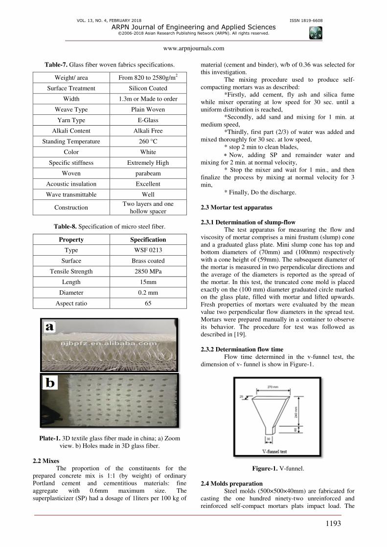
that compose the fabric. Plats (1) show the surface,
thickness and fibers holes). 3D glass fiber textile woven
export from china. Tables (6, 7 and 8) shows typical
properties, Fabrics Specifications.
2.1.7 Mesh chicken wire
The Rhombic shape meshes of reinforcement,
fabricated from 0.54mm –nominal diameter steel bars, the
opinion in the long and short direction (10.6, 7.92mm)
respectively.
2.1.8 Micro steel fiber
Steel fibers are used in self compact mortars
(SCMs) to enhance some properties and improve the
ductility; it was manufactured by Ganzhou Daye Metallic
Fiber Co., Ltd, China. (http//www.gzdymf.com), it is
subjected to (ISO 9001/2008) the properties are
summarized in Table-9. After poured first layer of self
compact mortars; micro steel fiber (0.75%) volume
fraction was randomly distribution by hand.
Table-3. Properties of fine aggregate.
Physical
properties* Test results
Iraqi
specification.
45/1984[14]
Specific gravity 2.65 -
Sulfate content 0.3 % Not more than
0.5%
Absorption 1 % -
Bulk
density(kg/m3)
1560 -
Table-4. Physical and chemical properties of class (F) fly
ash.
ASTM C 618
Class F fly ash [16 ]
Fly ash
(Class F) Particular
Chemical
composition
SiO2 + Al2O3+
Fe2O3) ≥ 70)
65.65 (Silica (SiO2%
17.69 % Alumina
(Al2O3)
5.98 Iron Oxide
(Fe2O3) %
0.98 Lime (CaO) %
0.72 Magnesia (MgO)
%
Max. 5.0 0.19 % Sulphur
Trioxide (SO3)
Max. 6.0 3.1 Loss on Ignition
1.35 Na2O
2.98 K2O
Physical
properties
2.12 Specific gravity
Min. 2250cm2/gm 3600 Fineness (cm
2/gm)
Table-5. The technical specifications of silica fume.
Structure of
material Silica fume
Limits of
ASTM C
1240-05 [17]
Color Dark gray
Density 0.55-0.7 kg/m3
Chlorine amount < 0.1 %
Specific surface
area (cm2/gm)
> 150000 cm2/g
≥ 150000 cm
2/g
SiO2 > 85 % ≥ 85 %
CaO < 1 %
Activity index* 156 % ≥ 105 %
Specific gravity 2.2
Table-6. Glass fiber woven fabrics specification.
Tensile
strength
(MPa) weft
(n/50mm)
Tensile
strength
(MPa) warp
(n/50mm)
Density of
weft (ends
/cm)
Density of
warp (ends
/cm)
Core
(mm)
Area weight
(g/m2)
9400 5500 10 15 6 900
12000 6800 8 15 10 1480
13000 7200 6 12 15 1650
VOL. 13, NO. 4, FEBRUARY 2018 ISSN 1819-6608
ARPN Journal of Engineering and Applied Sciences ©2006-2018 Asian Research Publishing Network (ARPN). All rights reserved.
www.arpnjournals.com
1193
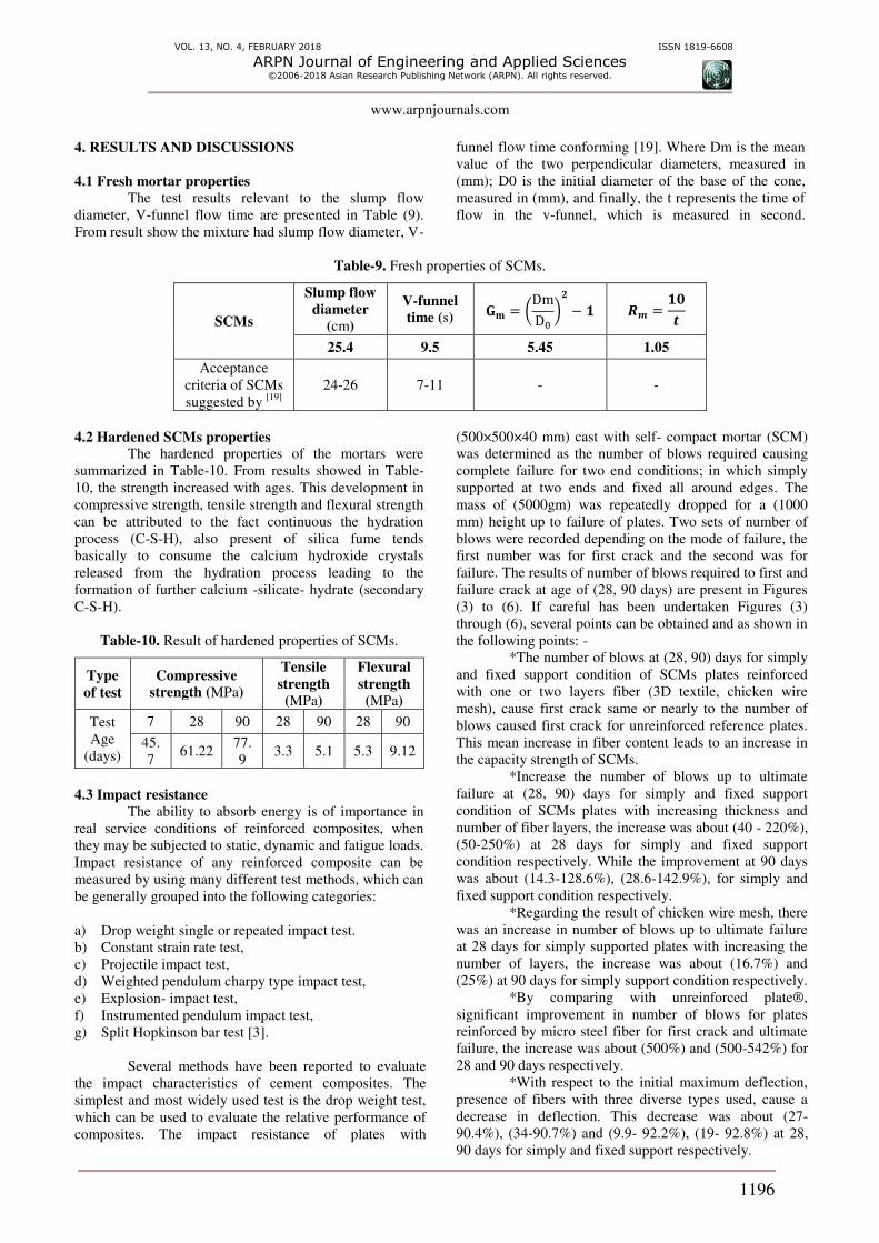
Table-7. Glass fiber woven fabrics specifications.
Weight/ area From 820 to 2580g/m2
Surface Treatment Silicon Coated
Width 1.3m or Made to order
Weave Type Plain Woven
Yarn Type E-Glass
Alkali Content Alkali Free
Standing Temperature 260 °C
Color White
Specific stiffness Extremely High
Woven parabeam
Acoustic insulation Excellent
Wave transmittable Well
Construction Two layers and one
hollow spacer
Table-8. Specification of micro steel fiber.
Specification Property
WSF 0213 Type
Brass coated Surface
2850 MPa Tensile Strength
15mm Length
0.2 mm Diameter
65 Aspect ratio
Plate-1. 3D textile glass fiber made in china; a) Zoom
view. b) Holes made in 3D glass fiber.
2.2 Mixes
The proportion of the constituents for the
prepared concrete mix is 1:1 (by weight) of ordinary
Portland cement and cementitious materials: fine
aggregate with 0.6mm maximum size. The
superplasticizer (SP) had a dosage of 1liters per 100 kg of
material (cement and binder), w/b of 0.36 was selected for
this investigation.
The mixing procedure used to produce self-
compacting mortars was as described:
*Firstly, add cement, fly ash and silica fume
while mixer operating at low speed for 30 sec. until a
uniform distribution is reached,
*Secondly, add sand and mixing for 1 min. at
medium speed,
*Thirdly, first part (2/3) of water was added and
mixed thoroughly for 30 sec. at low speed,
* stop 2 min to clean blades,
Now, adding SP and remainder water and
mixing for 2 min. at normal velocity,
* Stop the mixer and wait for 1 min., and then
finalize the process by mixing at normal velocity for 3
min,
* Finally, Do the discharge.
2.3 Mortar test apparatus
2.3.1 Determination of slump-flow
The test apparatus for measuring the flow and
viscosity of mortar comprises a mini frustum (slump) cone
and a graduated glass plate. Mini slump cone has top and
bottom diameters of (70mm) and (100mm) respectively
with a cone height of (59mm). The subsequent diameter of
the mortar is measured in two perpendicular directions and
the average of the diameters is reported as the spread of
the mortar. In this test, the truncated cone mold is placed
exactly on the (100 mm) diameter graduated circle marked
on the glass plate, filled with mortar and lifted upwards.
Fresh properties of mortars were evaluated by the mean
value two perpendicular flow diameters in the spread test.
Mortars were prepared manually in a container to observe
its behavior. The procedure for test was followed as
described in [19].
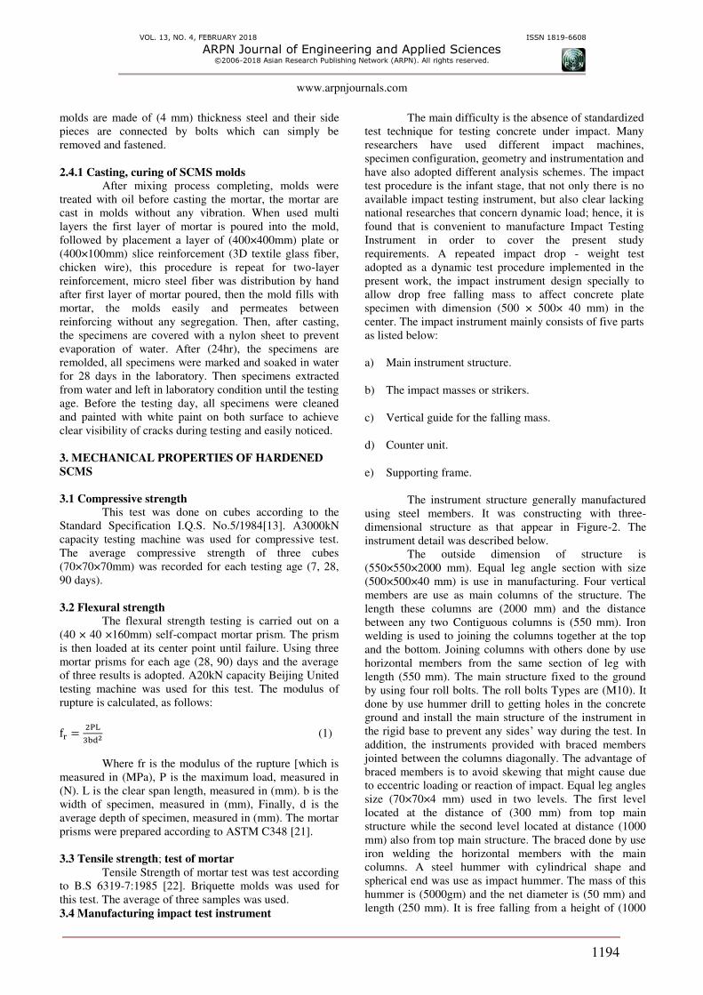
2.3.2 Determination flow time
Flow time determined in the v-funnel test, the
dimension of v- funnel is show in Figure-1.
Figure-1. V-funnel.
2.4 Molds preparation
Steel molds (500×500×40mm) are fabricated for
casting the one hundred ninety-two unreinforced and
reinforced self-compact mortars plats impact load. The
VOL. 13, NO. 4, FEBRUARY 2018 ISSN 1819-6608
ARPN Journal of Engineering and Applied Sciences ©2006-2018 Asian Research Publishing Network (ARPN). All rights reserved.
www.arpnjournals.com
1194
molds are made of (4 mm) thickness steel and their side
pieces are connected by bolts which can simply be
removed and fastened.
2.4.1 Casting, curing of SCMS molds
After mixing process completing, molds were
treated with oil before casting the mortar, the mortar are
cast in molds without any vibration. When used multi
layers the first layer of mortar is poured into the mold,
followed by placement a layer of (400×400mm) plate or
(400×100mm) slice reinforcement (3D textile glass fiber,
chicken wire), this procedure is repeat for two-layer
reinforcement, micro steel fiber was distribution by hand
after first layer of mortar poured, then the mold fills with
mortar, the molds easily and permeates between
reinforcing without any segregation. Then, after casting,
the specimens are covered with a nylon sheet to prevent
evaporation of water. After (24hr), the specimens are
remolded, all specimens were marked and soaked in water
for 28 days in the laboratory. Then specimens extracted
from water and left in laboratory condition until the testing
age. Before the testing day, all specimens were cleaned
and painted with white paint on both surface to achieve
clear visibility of cracks during testing and easily noticed.
3. MECHANICAL PROPERTIES OF HARDENED
SCMS
3.1 Compressive strength
This test was done on cubes according to the
Standard Specification I.Q.S. No.5/1984[13]. A3000kN
capacity testing machine was used for compressive test.
The average compressive strength of three cubes
(70×70×70mm) was recorded for each testing age (7, 28,
90 days).
3.2 Flexural strength
The flexural strength testing is carried out on a
(40 × 40 ×160mm) self-compact mortar prism. The prism
is then loaded at its center point until failure. Using three
mortar prisms for each age (28, 90) days and the average
of three results is adopted. A20kN capacity Beijing United
testing machine was used for this test. The modulus of
rupture is calculated, as follows:
fr = PLbd2 (1)
Where fr is the modulus of the rupture [which is
measured in (MPa), P is the maximum load, measured in
(N). L is the clear span length, measured in (mm). b is the
width of specimen, measured in (mm), Finally, d is the
average depth of specimen, measured in (mm). The mortar
prisms were prepared according to ASTM C348 [21].
3.3 Tensile strength; test of mortar
Tensile Strength of mortar test was test according
to B.S 6319-7:1985 [22]. Briquette molds was used for
this test. The average of three samples was used.
3.4 Manufacturing impact test instrument
The main difficulty is the absence of standardized
test technique for testing concrete under impact. Many
researchers have used different impact machines,
specimen configuration, geometry and instrumentation and
have also adopted different analysis schemes. The impact
test procedure is the infant stage, that not only there is no
available impact testing instrument, but also clear lacking
national researches that concern dynamic load; hence, it is
found that is convenient to manufacture Impact Testing
Instrument in order to cover the present study
requirements. A repeated impact drop - weight test
adopted as a dynamic test procedure implemented in the
present work, the impact instrument design specially to
allow drop free falling mass to affect concrete plate
specimen with dimension (500 × 500× 40 mm) in the
center. The impact instrument mainly consists of five parts
as listed below:
a) Main instrument structure.
b) The impact masses or strikers.
c) Vertical guide for the falling mass.
d) Counter unit.
e) Supporting frame.
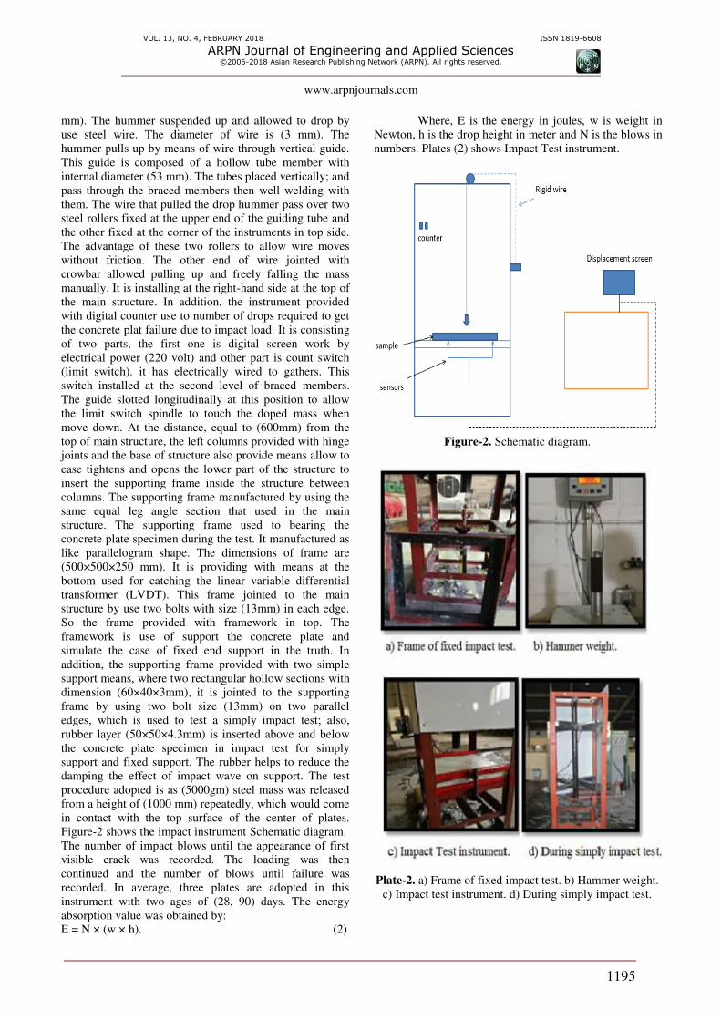
The instrument structure generally manufactured
using steel members. It was constructing with three-
dimensional structure as that appear in Figure-2. The
instrument detail was described below.
The outside dimension of structure is
(550×550×2000 mm). Equal leg angle section with size
(500×500×40 mm) is use in manufacturing. Four vertical
members are use as main columns of the structure. The
length these columns are (2000 mm) and the distance
between any two Contiguous columns is (550 mm). Iron
welding is used to joining the columns together at the top
and the bottom. Joining columns with others done by use
horizontal members from the same section of leg with
length (550 mm). The main structure fixed to the ground
by using four roll bolts. The roll bolts Types are (M10). It
done by use hummer drill to getting holes in the concrete
ground and install the main structure of the instrument in
the rigid base to prevent any sides’ way during the test. In
addition, the instruments provided with braced members
jointed between the columns diagonally. The advantage of
braced members is to avoid skewing that might cause due
to eccentric loading or reaction of impact. Equal leg angles
size (70×70×4 mm) used in two levels. The first level
located at the distance of (300 mm) from top main
structure while the second level located at distance (1000
mm) also from top main structure. The braced done by use
iron welding the horizontal members with the main
columns. A steel hummer with cylindrical shape and
spherical end was use as impact hummer. The mass of this
hummer is (5000gm) and the net diameter is (50 mm) and
length (250 mm). It is free falling from a height of (1000
VOL. 13, NO. 4, FEBRUARY 2018 ISSN 1819-6608
ARPN Journal of Engineering and Applied Sciences ©2006-2018 Asian Research Publishing Network (ARPN). All rights reserved.
www.arpnjournals.com
1195
mm). The hummer suspended up and allowed to drop by
use steel wire. The diameter of wire is (3 mm). The
hummer pulls up by means of wire through vertical guide.
This guide is composed of a hollow tube member with
internal diameter (53 mm). The tubes placed vertically; and
pass through the braced members then well welding with
them. The wire that pulled the drop hummer pass over two
steel rollers fixed at the upper end of the guiding tube and
the other fixed at the corner of the instruments in top side.
The advantage of these two rollers to allow wire moves
without friction. The other end of wire jointed with
crowbar allowed pulling up and freely falling the mass
manually. It is installing at the right-hand side at the top of
the main structure. In addition, the instrument provided
with digital counter use to number of drops required to get
the concrete plat failure due to impact load. It is consisting
of two parts, the first one is digital screen work by
electrical power (220 volt) and other part is count switch
(limit switch). it has electrically wired to gathers. This
switch installed at the second level of braced members.
The guide slotted longitudinally at this position to allow
the limit switch spindle to touch the doped mass when
move down. At the distance, equal to (600mm) from the
top of main structure, the left columns provided with hinge
joints and the base of structure also provide means allow to
ease tightens and opens the lower part of the structure to
insert the supporting frame inside the structure between
columns. The supporting frame manufactured by using the
same equal leg angle section that used in the main
structure. The supporting frame used to bearing the
concrete plate specimen during the test. It manufactured as
like parallelogram shape. The dimensions of frame are
(500×500×250 mm). It is providing with means at the
bottom used for catching the linear variable differential
transformer (LVDT). This frame jointed to the main
structure by use two bolts with size (13mm) in each edge.
So the frame provided with framework in top. The
framework is use of support the concrete plate and
simulate the case of fixed end support in the truth. In
addition, the supporting frame provided with two simple
support means, where two rectangular hollow sections with
dimension (60×40×3mm), it is jointed to the supporting
frame by using two bolt size (13mm) on two parallel
edges, which is used to test a simply impact test; also,
rubber layer (50×50×4.3mm) is inserted above and below
the concrete plate specimen in impact test for simply
support and fixed support. The rubber helps to reduce the
damping the effect of impact wave on support. The test
procedure adopted is as (5000gm) steel mass was released
from a height of (1000 mm) repeatedly, which would come
in contact with the top surface of the center of plates.
Figure-2 shows the impact instrument Schematic diagram. The number of impact blows until the appearance of first
visible crack was recorded. The loading was then
continued and the number of blows until failure was
recorded. In average, three plates are adopted in this
instrument with two ages of (28, 90) days. The energy
absorption value was obtained by:
E = N × (w × h). (2)
Where, E is the energy in joules, w is weight in
Newton, h is the drop height in meter and N is the blows in
numbers. Plates (2) shows Impact Test instrument.
Figure-2. Schematic diagram.
Plate-2. a) Frame of fixed impact test. b) Hammer weight.
c) Impact test instrument. d) During simply impact test.
VOL. 13, NO. 4, FEBRUARY 2018 ISSN 1819-6608
ARPN Journal of Engineering and Applied Sciences ©2006-2018 Asian Research Publishing Network (ARPN). All rights reserved.
www.arpnjournals.com
1196
4. RESULTS AND DISCUSSIONS
4.1 Fresh mortar properties
The test results relevant to the slump flow
diameter, V-funnel flow time are presented in Table (9).
From result show the mixture had slump flow diameter, V-
funnel flow time conforming [19]. Where Dm is the mean
value of the two perpendicular diameters, measured in
(mm); D0 is the initial diameter of the base of the cone,
measured in (mm), and finally, the t represents the time of
flow in the v-funnel, which is measured in second.
Table-9. Fresh properties of SCMs.
SCMs
Slump flow
diameter
(cm)
V-funnel
time (s) 𝐆𝐦 = (DmD0 ) − 𝑹𝒎 = 𝒕
25.4 9.5 5.45 1.05
Acceptance
criteria of SCMs
suggested by [19]
24-26 7-11 - -
4.2 Hardened SCMs properties The hardened properties of the mortars were
summarized in Table-10. From results showed in Table-
10, the strength increased with ages. This development in
compressive strength, tensile strength and flexural strength
can be attributed to the fact continuous the hydration
process (C-S-H), also present of silica fume tends
basically to consume the calcium hydroxide crystals
released from the hydration process leading to the
formation of further calcium -silicate- hydrate (secondary
C-S-H).
Table-10. Result of hardened properties of SCMs.
Flexural
strength
(MPa)
Tensile
strength
(MPa)
Compressive
strength (MPa) Type
of test
90 28 90 28 90 28 7 Test
Age
(days) 9.12 5.3 5.1 3.3 77.
9 61.22
45.
7
4.3 Impact resistance
The ability to absorb energy is of importance in
real service conditions of reinforced composites, when
they may be subjected to static, dynamic and fatigue loads.
Impact resistance of any reinforced composite can be
measured by using many different test methods, which can
be generally grouped into the following categories:
a) Drop weight single or repeated impact test.
b) Constant strain rate test,
c) Projectile impact test,
d) Weighted pendulum charpy type impact test,
e) Explosion- impact test,
f) Instrumented pendulum impact test,
g) Split Hopkinson bar test [3].
Several methods have been reported to evaluate
the impact characteristics of cement composites. The
simplest and most widely used test is the drop weight test,
which can be used to evaluate the relative performance of
composites. The impact resistance of plates with
(500×500×40 mm) cast with self- compact mortar (SCM)
was determined as the number of blows required causing
complete failure for two end conditions; in which simply
supported at two ends and fixed all around edges. The
mass of (5000gm) was repeatedly dropped for a (1000
mm) height up to failure of plates. Two sets of number of
blows were recorded depending on the mode of failure, the
first number was for first crack and the second was for
failure. The results of number of blows required to first and
failure crack at age of (28, 90 days) are present in Figures
(3) to (6). If careful has been undertaken Figures (3)
through (6), several points can be obtained and as shown in
the following points: -
*The number of blows at (28, 90) days for simply
and fixed support condition of SCMs plates reinforced
with one or two layers fiber (3D textile, chicken wire
mesh), cause first crack same or nearly to the number of
blows caused first crack for unreinforced reference plates.
This mean increase in fiber content leads to an increase in
the capacity strength of SCMs.
*Increase the number of blows up to ultimate
failure at (28, 90) days for simply and fixed support
condition of SCMs plates with increasing thickness and
number of fiber layers, the increase was about (40 - 220%),
(50-250%) at 28 days for simply and fixed support
condition respectively. While the improvement at 90 days
was about (14.3-128.6%), (28.6-142.9%), for simply and
fixed support condition respectively.
*Regarding the result of chicken wire mesh, there
was an increase in number of blows up to ultimate failure
at 28 days for simply supported plates with increasing the
number of layers, the increase was about (16.7%) and
(25%) at 90 days for simply support condition respectively.
*By comparing with unreinforced plate®,
significant improvement in number of blows for plates
reinforced by micro steel fiber for first crack and ultimate
failure, the increase was about (500%) and (500-542%) for
28 and 90 days respectively.
*With respect to the initial maximum deflection,
presence of fibers with three diverse types used, cause a
decrease in deflection. This decrease was about (27-
90.4%), (34-90.7%) and (9.9- 92.2%), (19- 92.8%) at 28,
90 days for simply and fixed support respectively.

VOL. 13, NO. 4, FEBRUARY 2018 ISSN 1819-6608
ARPN Journal of Engineering and Applied Sciences ©2006-2018 Asian Research Publishing Network (ARPN). All rights reserved.
www.arpnjournals.com
1197
*Final maximum deflection has decreased by
fibers introducing, it has decrease about (15.7- 52.8%),
(11.8-27.9%) and (8.9- 44.6%), (6.5- 44%) at 28, 90 days
for simply and fixed support respectively. By comparing
with reference SCMs plate the maximum deflection has
decreased by increase number of layers of 6 mm 3D textile
glass fiber, it has decreased about (5, 7%) and (16, 17.6%)
at 28, 90 days for simply and fixed support respectively.
Also, the maximum deflection has been decreased by
increasing number of 10 mm 3D textile glass fiber layers
by about (21.1, 28.5%) and (25, 31%), at 28, 90 days for
simply and fixed support respectively.
*Regarding micro steel fiber reinforced SCMs
plate, the initial deflection has significant reduction. The
reduction was about (68.6, 67.7%) and (68.4, 64.9%), and
the final deflection shows the same behavior and cause
reduction by about (12.7, 11.8%) and (33, 34.4%) at 28, 90
days for simply and fixed support respectively.
*In spite of different and increased in number of
blows caused initial and ultimate failure. The deflections of
plates with simply supported condition were larger than
those for plates with fixed supports by a range of (5.3,
20.4%) and (2, 21.1%), for the tested plate specimens at
28, 90 days for simply and fixed support respectively.
*Regarding SCMs plate reinforced with 6mm
3Dtextile glass fiber slice (one, two) layers shows the same
behaviors (maximum deflection) has been decreased, the
decrease was about (29, 38.6%), (59.6, 62%) and (40.7,
41%), (54.6, 87.6%) for one and two layers of 6mm
3Dtextile glass fiber at 28, 90 days for simply and fixed
support respectively. From Tables (12,13) and figures
(3,4), 6mm 3Dtextile glass fiber slice two way reinforced
has significantly enhancement in number of blows, the
improvement was about (80, 125%) and (128.5, 114.3%),
also max deflection was reduced, the reduction was about
(90.5, 90.7%) and (92.3, 92.8%) at 28, 90 days for simply
and fixed support respectively.
*With respect to the maximum deflection has
been decreased by increasing number of layers of 10 mm
3D textile glass fiber, it has decreased about (21.1, 28.5%)
and (25, 31%), while the reduction in deflection about (3.5,
8.5%) and (9.1%) at 28, 90 days for simply and fixed
support respectively.
*The number of blows up to ultimate failure at
(28, 90) days for simply and fixed support condition of
SCMs plates enhancement with increasing thickness and
number of fiber layers, this mean increase in fiber content
and leads to an increase in the capacity strength of SCMs.
Figure-3. Number of blows to first and failure crack of
fixed and simply support at (28, 90) days.
Figure-4. First and failure number of blows at ages
(28, 90 days).
Figure-5. Max deflection for initial simple and fixed
impact at (28, 90 days).
0
5
10
15
20
25
30
35
40
45
No
. o
f b
low
Mix ID
initial crack in simply support ( 28 days)
failure crack in simply support ( 28 days
initial crack in fixed support ( 28 days)
failure crack in fixed support ( 28 days)
initial crack in simply support ( 90 days)
failure crack in simply support ( 90 (days
0
5
10
15
20
25
30
35
40
45
R
F6
/1
F6
/2
F6
/1/S
F6
/2/S
F6/2/…
F1
0/1
F1
0/2
F1
5
FS
/1
FS
/2
F M
S
No
. o
f b
low
Mix ID
initial crack in simply support ( 90 days)
failure crack in simply support ( 90 (days
initial crack in fixed support ( 90 days)
failure crack in fixed (support (90 days
0
0.2
0.4
0.6
0.8
1
1.2
1.4
1.6
1.8
2
R
F6/1
F6/2
F6/1
/S
F6/2
/S
F6/2
/S/T
F10
/1
F10
/2
F15
FS
/1
FS
/2
FM
S
Def
lect
ion
(m
m)
Mix ID
Max Deflection
(mm) for initial
simple impact at
28 days
Max Deflection
(mm) for initial
fixed impact at
28 days
Max Deflection
(mm) for initial
simple impact
at 90 days
Max Deflection
(mm) for initial
fixed impact at
90 days

VOL. 13, NO. 4, FEBRUARY 2018 ISSN 1819-6608
ARPN Journal of Engineering and Applied Sciences ©2006-2018 Asian Research Publishing Network (ARPN). All rights reserved.
www.arpnjournals.com
1198
Figure-6. Max deflection (mm) for final simple and fixed
impact (28, 90 days).
4.4 Energy absorption The total energy absorbed by the SCMs plates
when struck by a hard impact or depends on the local
energy absorbed both in contact zone and by the impact or.
The energy absorption can be obtained by using formula
described in section (3.4).
The ratio of energy absorbed up to the failure of
specimens to the energy absorbed at initiation of first
crack is defined as the "Residual Impact Strength
Ratio"(Irs). The energy absorption capacities of SCMs
plates at initial crack and at ultimate failure stages and
residual impact strength are presented in Figures (7, 8).
From the results that the energy absorbed increase with
increase the number of layers and increase in thickness of
3Dtextile glass fiber improve the impact energy absorption
compared to the no reinforcement plates ®. The energy
absorbed at failure is directly proportional to the volume
of the reinforcement (thickness, layers number) provided
in the SCMs plates. Of the three types of reinforcement,
micro steel fiber, 3D textile glass fiber (10mm thickness
and 6mm slice two-way reinforcement) have absorbed
higher energy compare to the other types. This may be due
to the higher ductility embrittlement of reinforcement.
Figure-7. Energy absorption capacity at (28, 90( days for fixed and simply support.
Figure-8. Residual impact strength at (28, 90( days for fixed and simply support.
4.5 Crack patterns
A high quality Portable microscope designed for
measuring crack widths in concrete members was used to
measured initial and final crack width, the larger cracks
were measured by used Vernier caliper. The fact of crack
patterns and failure modes in impact load often depend on
position of striker and plat to towards the supports. In
present study, the crack patterns for all SCMs plates were
in diagonal direction and start from center point (mean the
center of plate where mass is falling) then propagation in
all direction in lines perpendicular to its edges, the width
of cracks were different from plat specimen to another
where they depend on plat stiffness. From result shown in
Figure-9, the following points describe the cracks
formation and propagation after impact load:
*The SCMs plate which has no reinforcement ®
was strongly influenced by impact load and significant
cracks has propagated rapidly.
*Average crack width has decreased by
introduced different type of fibers (3D textile glass,
chicken wire mesh, micro steel).
*Average crack width has decreased by
increasing the thickness and layer numbers of 3D textile
0
10
20
30
40
De
fle
ctio
n (
mm
)
Mix ID
Max Deflection (mm) for failure simple impact 28days)
Max Deflection(mm) for failure fixed impact 28 days
Max Deflection (mm)for failure simple impact 90 days
Max Deflection(mm) for failure fixed impact 90 days
0
2
4
6
8
Res
idu
al I
mp
act
Str
ength
Rat
io (
Irs)
Mix ID
(Irs) Simple (28 days) (Irs) Fixed (28 days) (Irs) Simple (90 days) (Irs) Fixed ( 90 days )

VOL. 13, NO. 4, FEBRUARY 2018 ISSN 1819-6608
ARPN Journal of Engineering and Applied Sciences ©2006-2018 Asian Research Publishing Network (ARPN). All rights reserved.
www.arpnjournals.com
1199
glass fiber reinforce SCMs plate, also increase number of
chicken wire mesh from one to two layers and micro steel
fiber in reinforced SCMs plate decreased the average
crack width.
*Regarding the average crack width, crack
propagation in micro steel fiber reinforced SCMs plates
was much less as compared to cracks in plates without
micro steel fibers. The cause of that result may be due to
the influence of mixing action the fiber are uniformly
distrusted fibers disallow the micro crack from developing
into macrocracks and potential troubles, in addition these
fibers bridge and therefore hold together the existing
macro crack thus reinforcing the concrete against
disintegration.
Smaller crack pattern for all plates are shown in
plates (3) through (6), The failure mode was punching
with truncated cone shape, the increasing in thickness and
number of fiber decreases the cracks width and change the
plate behavior from the localized punching to global
response, hence, the behavior of the normal concrete in
this point seems look like the behavior of SCMs plate. It is
clear that increasing thickness and fiber layers numbers,
also introduce micro steel fiber and chicken wire mesh
will increase the capacity of SCMs plates and this is a
cause why the maximum deflection has decreased. On the
other hand, micro steel fiber is highly influenced not only
on cracks width, but also affected on the number of cracks,
this perhaps reverts that micro steel fiber is sufficient to
make bridging amongst the invisible cracks, in other
meaning, micro steel fibers have disallowed cracks
propagating.
Finally, it is suitable to show that (Trevor and Frank,
2014) [22]
studied the effect of steel fiber in reinforced
normal concrete plate under impact load, they concluded
that increasing micro steel fiber decreases the cracks width
and change the plate behavior from the localized punching
to global response, hence, the behavior of the normal
concrete in this point seems look like the behavior of
SCMs plate simply support, but not agreement with they
for fixed support, the failure is local with very few visible
yield line from center to corner.
The behavior of SCMs plate that had amounts of
micro steel fiber is better than other those plate specimens
because they have not only reduced the deflection
significantly, cracks width, mitigating local damage under
impact and spacing but also the number of cracks was too
few, in other words, micro steel fiber increasing plate
capacity, and created bridging better than other fiber
reinforced SCMs plates. The failure pattern at the point of
contact of the drop weight and no fragments detached
from the plates specimens as the various layers of the fiber
reinforcement assisted to hold the different fragments
together. It can thus infer that several types fiber used as
reinforcement SCMs plates, play a significant role in not
only enhancement the impact energy absorption, but also
retain various fragments together. All the cracks reached
from center to edge of the plats. The increasing in
thickness and number of layers, multiple cracks with small
crack width propagated up to the edge and cracks are
interconnected like network.
Figure-9. Initial and final crack width for simply and fixed support at (28, 90) days.
Plate-3. Crack pattern of micro steel fibre: a) initial crack
of simply support. b) final crack of simply support.
Plate-4. Crack pattern of micro steel fibre: a) initial crack
of simply support. b) final crack of simply support.

VOL. 13, NO. 4, FEBRUARY 2018 ISSN 1819-6608
ARPN Journal of Engineering and Applied Sciences ©2006-2018 Asian Research Publishing Network (ARPN). All rights reserved.
www.arpnjournals.com
1200
Plate-5. Crack pattern of micro steel fibre: a) initial crack
of simply support. b) final crack of simply support.
Plate-6. Crack pattern of micro steel fibre: a) initial crack
of simply support. b) final crack of simply support.
5. CONCLUSIONS
a) The maximum deflection has been decreased by
increasing the thickness and number of layers fiber, it
has decreased while the maximum deflection was
reduction at 28, 90 days for simply and fixed support.
b) The number of blows up to ultimate failure at (28, 90)
days for simply and fixed support condition of SCMs
plates enhancement with increasing thickness and
number of fiber layers and introduce micro steel fiber.
c) The energy absorbed increase with increase the
number of layers and increase in thickness of
3Dtextile glass fiber improve the impact energy
absorption compared to the no reinforcement plates
®.
d) The SCMs plate which has no reinforcement ® was
strongly influenced by impact load and significant
cracks has propagated rapidly.
e) Average crack width has decreased by introduced
different type of fibers (3D textile glass, chicken wire
mesh, micro steel).
f) Average crack width has decreased by increasing the
thickness and layer numbers of 3D textile glass fiber
reinforce SCMs plate, also increase number of
chicken wire mesh from one to two layers and micro
steel fiber in reinforced SCMs plate decreased the
average crack width.
REFERENCES
[1] Gholipour Y. 2004. Impact resistance of composite
plate. Structural Concrete. 5(2): 57-60.
[2] Neville A.M. 1995. Properties of Concrete. Fourth
Edition, Wiley, New York and Longman, London. p.
343.
[3] T. Kiran, Sadath Ali Khan Zai and Srikant Reddy. S.
Impact test on geopolymer concrete slabs.
[4] S. Deepa shri and R. Thenmozhi. Prediction of Impact
Energy Absorption Using Modified Regression
Theory. Life Sci J 2013; 10(1):743-749]. (ISSN:
1097-8035).
[5] ACI_Committee 544-1R, (1996), "State of the art
report on fiber reinforced concrete", ACI manual of
concrete practice.
[6] Rao P.S. and Sekhar T.S. 2008. Impact Strength and
Workability Behavior of Glass Fiber Self Compacting
Concrete. International Journal of Mechanics and
Solids. 3(1): 61-74.
[7] A. Peled, D. Zhu, and B. Mobashe. 2012. Impact
Behavior of 3D Fabric Reinforced Cementitious
Composites. Montesinos, H.W. pp. 543-550.
[8] Elavenil S. and Samuel G.M. 2012. Impact Response
of Plates under Drop Weight Impact Testing.
International University Journal of Science and
Technology. 7(1).
[9] Trevor D. Hrynyk and Frank J. Vecchio. 2014.
Behavior of Steel Fiber-Reinforced Concrete Slabs
under Impact Load. ACI Structural Journal.
[10] G. Murali, E. Arun, A. Arun Prasadh, R. Infant raj
and T. Aswin Prasanth. 2014. Experimental
Investigation of Reinforced Ferrocement Concrete
Plates under Impact Load. International Journal of
Latest Research in Engineering and Computing
(IJLREC). 2(1): 01-04.
[11] Aziz, I.A., Hadeel, R. K. 2014. Behavior of
Multilayer Composite Ferrocement Slabs with
Intermediate Rubberized Cement Mortar Layer.
Arbian Journal for Science and Engineering. 39:
5929-5941.

VOL. 13, NO. 4, FEBRUARY 2018 ISSN 1819-6608
ARPN Journal of Engineering and Applied Sciences ©2006-2018 Asian Research Publishing Network (ARPN). All rights reserved.
www.arpnjournals.com
1201
[12] Seeram Apoorva, M Saiharan, M Aravinthan, H
Thamlm Ansari and M Neelamegam. 2016. Impact
Study on Ferrocement Slabs with Different Types of
Mortar Matrices. International Journal of Earth
Sciences and Engineering. ISSN 0974-5904, 09(03):
252-257.
[13] Iraqi standard specifications of number (5/1984).
Portland cement. Central Organization for
Standardization and Quality Control in Iraq. 1-10.
[14] Iraqi standard specification of number (5/1984). Ruins
the natural resources used in concrete construction.
Central Organization for Standardization and Quality
Control in Iraq. 1-16.
[15] 2005. ASTM C-494/C 494M-05. Standard
Specification for Chemical Admixtures for Concrete.
ASTM International, 100 Barr Harbor Drive, PO Box
C700, West Conshohocken, PA 19428-2959, United
States. pp. 1-10.
[16] American Society for Testing and Materials. 2003.
Standard specification for coal fly ash and raw or
calcined natural pozzolan for use in concrete. ASTM
C 618.
[17] 2007. ASTM C-1240-07. Standard Specification for
the Use of Silica Fume as a Mineral Admixture in
Hydraulic Cement Concrete, Mortar, and Grout.
04.02: 1-7.
[18] 2005. ASTM C-311-05. Standard Test Methods for
Sampling and Testing Fly Ash or Natural Pozzolans
for Use in Portland-Cement Concrete. ASTM
International, 100 Barr Harbor Drive, PO Box C700,
West Conshohocken, PA 19428-2959, United States.
pp. 1-7.
[19] EFNARC. 2002. Specification and Guidelines for
Self-Compacting Concrete. London. UK: Association
House, February. p. 32.
[20] ASTM C348-14, Standard Test Method for Flexural
Strength of Hydraulic-Cement Mortars standard by
ASTM International, 2014.
[21] 1985. B.S 6319-7 Part 116. Method for Determination
of Tensile Strength of Mortar. British Standard
Institution.
[22] Trevor D. Hrynyk and Frank J. Vecchio. 2014.
Behavior of Steel Fiber-Reinforced Concrete Slabs
under Impact Load. ACI Structural
Journal/September-October.