inverter commander se
DESCRIPTION
manual inverter comander se de control tecniquesTRANSCRIPT

www.controltechniques.com
EF
Advanced User Guide
Commander SE
Variable speed drive for 3 phase induction motors from 0.25kW to 37kW
Part Number: 0452-0049-04Issue Number: 4
EF

Safety InformationPersons supervising and performing the electrical installation or maintenance of a Drive and/or an external Option Unit must be suitably qualified and competent in these duties. They should be given the opportunity to study and if necessary to discuss this User Guide before work is started.
The voltages present in the Drive and external Option Units are capable of inflicting a severe electric shock and may be lethal. The Stop function of the Drive does not remove dangerous voltages from the terminals of the Drive and external Option Unit. Mains supplies should be removed and left removed for a minimum of 10 minutes before any servicing work is performed.
The installation instructions should be adhered to. Any questions or doubt should be referred to the supplier of the equipment. It is the responsibility of the owner or user to ensure that the installation of the Drive and external Option Unit, and the way in which they are operated and maintained complies with the requirements of the Health and Safety at Work Act in the United Kingdom and applicable legislation and regulations and codes of practice in the UK or elsewhere.
The Drive software may incorporate an optional Auto-start facility. In order to prevent the risk of injury to personnel working on or near the motor or its driven equipment and to prevent potential damage to equipment, users and operators, all necessary precautions must be taken if operating the Drive in this mode.
The Stop and Start inputs of the Drive should not be relied upon to ensure safety of personnel. If a safety hazard could exist from unexpected starting of the Drive, an interlock should be installed to prevent the motor being inadvertently started.
General InformationThe manufacturer accepts no liability for any consequences resulting from inappropriate, negligent or incorrect installation or adjustment of the optional operating parameters of the equipment or from mismatching the Drive with the motor.
The contents of this User Guide are believed to be correct at the time of printing. In the interests of a commitment to a policy of continuous development and improvement, the manufacturer reserves the right to change the specification of the product or its performance, or the contents of the User Guide, without notice.
All rights reserved. No part of this User Guide may be reproduced or transmitted in any form or by any means, electrical or mechanical including photocopying, recording or by any information storage or retrieval system, without permission in writing from the publisher.
Important! Drive software versionThis product is supplied with the latest version of user interface and machine control software. Please check that it is compatible with your application, i.e. if you already have Drives running in a system, there may be some differences between the existing software and the updated product software, causing varying functionality. This may also apply to Drives returned from Control techniques Service Centre.
If in doubt, please contact your nearest Control Techniques Drive Centre.
Copyright © June 2004 Control Techniques Drives Limited
Issue Code: 4
Software: V02.00.01 and greater

Contents1 Serial Communications .................................................................................... 5
1.1 Introduction ............................................................................................................................. 51.2 Serial communications connections ....................................................................................... 91.3 ANSI Protocol Description .................................................................................................... 101.4 Modbus RTU ........................................................................................................................ 14
2 Parameter Types ............................................................................................. 162.1 Drive Reset ........................................................................................................................... 162.2 Storing drive parameters ...................................................................................................... 162.3 Key to parameter codes ....................................................................................................... 16
3 Menus............................................................................................................... 173.1 Menu 1: Speed reference selection, limits and filters ......................................................... 183.2 Menu 2: Ramps .................................................................................................................... 263.3 Menu 3: Speed sensing thresholds ...................................................................................... 333.4 Menu 4: Current control ........................................................................................................ 353.5 Menu 5: Machine control ...................................................................................................... 423.6 Menu 6: Drive sequencer ..................................................................................................... 513.7 Menu 7: Analog inputs and outputs ...................................................................................... 613.8 Menu 8: Digital inputs and outputs ....................................................................................... 663.9 Menu 9: Programmable logic and motorised pot .................................................................. 733.10 Menu10: Status and trips ..................................................................................................... 773.11 Menu 11: Miscellaneous ....................................................................................................... 843.12 Menu 12: Threshold detector ............................................................................................... 893.13 Menu 14: PID control ............................................................................................................ 943.14 Menu 15: Fieldbus option parameters .................................................................................. 993.15 Menu 21: Second motor map ............................................................................................. 102
4 Drive Information .......................................................................................... 1074.1 Power Terminal Connections ............................................................................................. 1074.2 Commander SE power circuit layouts ................................................................................ 1084.3 Gland plate holes ............................................................................................................... 1094.4 Control terminal connections .............................................................................................. 1104.5 Serial communication connections ..................................................................................... 1104.6 Control terminal specifications ........................................................................................... 1114.7 Calculating the enclosure size ............................................................................................ 1144.8 Commander SE losses ....................................................................................................... 1164.9 Derating Curves ................................................................................................................. 1174.10 DC Bus information ............................................................................................................ 1294.11 High-capacitance cables .................................................................................................... 1304.12 Storage and transportation ................................................................................................. 131
5 Dynamic Braking........................................................................................... 1325.1 Sizing a braking resistor ..................................................................................................... 1335.2 Commander SE HF Faults ................................................................................................. 136
6 Input line reactors......................................................................................... 1377 Through-hole mounting plates .................................................................... 1438 Braking resistor brackets............................................................................. 1459 Dynamic braking resistors........................................................................... 14610 EMC cable screening bracket and screening clamps ............................... 14911 RFI Filters ...................................................................................................... 150
11.1 RFI Filter Dimensions ......................................................................................................... 15011.2 RFI Filter Data .................................................................................................................... 15311.3 Multiple motor applications ................................................................................................. 155
Commander SE Advanced User Guide 3Issue Number: 4

12 Applications ...................................................................................................15912.1 Connecting digital inputs in parallel .................................................................................... 15912.2 How to re-assign drive terminal input/output functions ....................................................... 16012.3 Commander SE user trips .................................................................................................. 16112.4 Analog input 2 ..................................................................................................................... 16212.5 Drive overload alarm signal connection .............................................................................. 16312.6 Motor thermistor set up ....................................................................................................... 16312.7 Drive set-up for 8 preset speeds ......................................................................................... 16412.8 Utilising dual motor set-up .................................................................................................. 16412.9 Commander SE analog output offset scaler ....................................................................... 16612.10 Brake set-up parameters .................................................................................................... 16812.11 Motorised potentiometer set-up .......................................................................................... 17212.12 Setting up Commander SE in torque mode ........................................................................ 17312.13 Torque control with speed override .................................................................................... 17312.14 Torque limiting .................................................................................................................... 17412.15 Keypad / Terminal Control .................................................................................................. 17512.16 Timed Digital Output ........................................................................................................... 17612.17 Variable Select Set-up (Selecting two levels of Voltage boost) .......................................... 17612.18 Analog input trim ................................................................................................................. 17712.19 Programmable threshold set-up ......................................................................................... 17912.20 PID loop .............................................................................................................................. 18012.21 2 x Latching Run Forward Inputs ........................................................................................ 18212.22 Jog Command .................................................................................................................... 18312.23 Flux Braking ........................................................................................................................ 18512.24 Variable Trim ...................................................................................................................... 18612.25 Quickey Compatibility ......................................................................................................... 18712.26 Controlling the Commander SE via the Universal Keypad ................................................. 18712.27 Open loop vector or fixed boost modes .............................................................................. 19012.28 Ramp Modes ...................................................................................................................... 19312.29 Stopping Modes .................................................................................................................. 194
4 Commander SE Advanced User GuideIssue Number: 4
1 Serial Communications1.1 Introduction
• 2-wire EIA485 via RJ45 connector• ANSI and Modbus RTU protocols supportedA serial communications link enables one or more drives to be used in systems controlled by a host unit such as a PLC (Programmable Logic Controller) or computer. The communications link for the drive uses the EIA485, also known as RS485, as standard for the hardware interface. The EIA422 hardware interface is also supported.The Commander SE drive has a standard 2-wire EIA485 half-duplex interface that enables all drive set-up, operation and monitoring to be accomplished if required. Therefore, it is possible to control the drive entirely by the EIA485 interface without the need for other control cabling. A host controller can operate up to thirty-two EIA485 devices with the use of one line buffer. Further buffers will increase this number if necessary. Each transmitter/receiver within a drive (with the internal termination and external pull-up and pull-down resistors disconnected) loads the EIA485 lines by 2 unit loads. This means that up to 15 drives can be connected in a single group to one line buffer. ANSI
When additional line buffers are used, up to 81 drives can be operated by the host controller. In this case the drives are organised in a maximum of 9 groups of 9 drives each. A particular drive or group of drives can be given commands without affecting other drives or groups of drives respectively.
Modbus RTUWhen additional line buffers are used, up to 247 drives can be operated by the host controller.
The serial communications port of the drive is situated at the RJ45 connector. Detailed instructions on how to terminate an RJ45 connector to comms cable are shown on the pages following. The EIA485 2-wire port is isolated from the power stage but not isolated from the other control terminals. The EIA422 hardware interface is also supported.
EIA232 to EIA485 CommunicationsAn external EIA232 hardware interface such as a PC cannot be used with the 2-wire EIA485 interface of the drive. Therefore a suitable converter is required. This converter must have the hardware and software support to tri-state (disable) the transmit buffer following message transmission. Otherwise the Commander SE EIA485 transmitter will not be successful in transmitting a reply as the host transmitter will cause contention of the 2-wire interface.
Examples of EIA232 to EIA485 converters (one to one):• Control Techniques SE71 communications lead (CT Part No. 4500-0087)
The Control Techniques SE71 communications lead is a specifically designed EIA232 to EIA485 converter to link a PC to a Commander SE drive.
• Amplicon 485Fi
These converters are for one to one connection between a PC and the Commander SE drive, They do not have 'multi-drop' capability.
The Control Techniques SE71 communications lead (part no: 4500-0087) and the Amplicon 485Fi converter are both isolated converters.
The SE71 2-wire EIA485 Serial Communications Converter – CT Part No: 4500-0087The SE71 2-wire EIA485 serial communications converter enables the use of serial communications with Commander SE using a software package such as SE Soft. This allows access of all the drives parameters and advanced function menus.The SE71 2-wire EIA485 serial communications converter is only intended for the purpose of commissioning a drive. Therefore:• It is not suitable for permanent installation• It does not provide connectivity to an EIA485 based networkWhen this converter is used on Commander SE and a true EIA232 host / master such as a PC, then no external power supply is required. This is because the converter sources its power from both the drive and the EIA232 ports.However, if the converter is attached to a host / master device that does not have a standard EIA232 port then an external power supply may be required. The SE71 2-wire EIA serial communication converter does not directly use any of the hand shaking functions that are available on a standard EIA232 port, but does utilise two of the hand shaking pins (4 and 7) as a source of power. If these signals are not available then a +10V supply should be applied to pins 4 and 7 with respect to pin 5 of the 9-way D-type connector.
NOTE
NOTE
Commander SE Advanced User Guide 5Issue Number: 4

Multi-drop Converters• Amplicon Magic 485F25 or Magic 485F9
(485F25 refers to 25 way D-type connector and 485F9 refers to 9 way D-type connector)www.amplicon.co.ukE-mail: [email protected]
• Westermo MA44www.westermo.dircon.co.ukE-mail: [email protected]
When using either of the above converters, or any other suitable converter with Commander SE, it is recommended that no terminating resistors be connected on the network. This applies to any of the drives on the network and also any converter used. It may be necessary to 'link out' the terminating resistor within the converter depending on which type is used. The information on how to link out the terminating resistor will normally be contained in the user information supplied with the converter. Terminating resistors are of little or no value when used on EIA485 networks operating at or below 19.2kBaud.
The Amplicon Magic 485F25 or F9 are non-isolated and the Westermo MA44 is isolated.
Isolation of the communications portThe communications port of the Commander SE drive is double-insulated from the power electronics and single-insulated from the status relay contacts. Providing that the voltage on the status relay contacts does not exceed 110V, the communications port meets the requirements for SELV in EN50178. However in the event of a serious fault in the drive, the safety barriers could be breached. Therefore when using the communications port with a personal computer or centralised controller e.g PLC, an isolation device must be included with rated voltage at least equal to the drive supply voltage. Ensure that the correct fuses are installed at the drive input, and that the drive is connected to the correct supply voltage.
Isolation Devices1. OP232/B1 Isolator
www.scimar.co.ukE-mail: [email protected]
2. 232SPM14 Isolator - 4 channel95POP2 Isolator - 2 channelwww.bb-elec.comwww.bb-europe.com
Fitting an RJ45 is a relatively simple process. The following instructions are provided to ensure a good reliable termination.
EIA232 9 WayD-type connector Pin Function EIA485
RJ45 Connector Pin Function
1 Not connected 1 Not connected2 TX 2 RXTX3 RX 3 0V4 DTR 4 +28V Input5 GND 5 Not connected6 Not connected 6 TXEN\7 RTS 7 RXTX\8 N/C 8 Not connected9 Not connected
NOTE
WARNING
6 Commander SE Advanced User GuideIssue Number: 4

What you will need:Figure 1-1 Stewart Shielded Plug
Figure 1-2 Stewart Ferrule Crimp Hand tool and 5.2mm Cable Crimp
Figure 1-3 RJ45 Hand tool, Shielded and Unsheilded Dies
All required components to terminate an RJ45 connector can be purchased from RS components. Refer to Table 1-1 on page 9 for RS Components part numbers.
Commander SE Advanced User Guide 7Issue Number: 4

Procedure1. Fit insulation boot over cable insulation.2. Strip approximately 25mm of the insulation and peel foil shield back over cable insulation
3. Fit the Ferrule flush with the cable insulation and crimp.
4. Remove cable wrap and fan out cables in the required order. Fit the cable spacer to within 2.5mm of the ferrule.
5. Cut cable to 6mm above cable spacer and fit into RJ45 ensuring all cables are in the correct channels and crimp.
6. Cut back foil shield flush with RJ45 connector and slide up insulation boot over the RJ45 connector.
8 Commander SE Advanced User GuideIssue Number: 4

Table 1-1 RS Components Part Numbers
The instructions provided are only applicable for Stewart manufactured RJ45 connectors.
1.2 Serial communications connectionsIf more than one drive is to be connected to a serial link, make connections as shown in the diagram below. • The serial communications cable must be shielded. The shield(s) must be connected as shown in the diagram below:
A data communications cable should not run parallel to any power cables, especially ones that connect drives to motors. If parallel runs are unavoidable, ensure a minimum spacing of 300mm (12 in.) between the communications cable and the power cable.
Cables crossing one another at right-angles are unlikely to give trouble. The maximum cable run length for a EIA485 link is 1,200 metres (4,000 feet).
If more than one drive is connected to the host computer, please adjust the serial address of each drive to ensure that each drive has a unique address. Therefore with the drive in the above condition, all commissioning and operation can be done using the EIA485 communication link.
T-Bar connector / splitter from Insight.Part No: CNX3A02KNWwww.insight.com
Pin 6 TX EnableThe TX Enable pin is a 0 to 5V output from the Drive that can be used to externally control and switch the buffers on a serial communications converter from transmit to receive and vice-versa. An example of a converter that can be used with this signal is the Amplicon 485Fi.
Description Part NumberStewart RJ45 Connectors 290-4780Ferrule Crimp Hand tool 290-48535.2mm Cable Crimp 290-48754.5mm Cable Crimp 290-4869RJ45 Hand tool 290-4796Shielded Die 290-4847Unshielded Die 290-4825
NOTE
NOTE
12345678
RJ45
RJ45 T-BARCONNECTOR
SYSTEMCONTROLLER
(RS485)TRANSCEIVER
Tx / Rx
Tx / Rx
Drive 1 Drive 2RJ45 CONNECTOR
PIN 1 TERMINATION RESISTOR
PIN 2 Rx Tx
PIN 3 0V
PIN 4 +26V
PIN 5 NOT USED
PIN 6 TX ENABLE
PIN 7 Rx Tx
PIN 8 LINKED TO PIN 7
12345678
RJ45
1 14 1 14
0V
Tx / Rx
Tx / Rx
Commander SE Advanced User Guide 9Issue Number: 4

1.3 ANSI Protocol DescriptionData is transmitted at a fixed speed or baud rate in the form of a character. A character is comprised of seven bits, and the baud rate represents the data transmission rate in bits/second.In order for a data receiver to recognise valid data, a frame is placed around each character. This frame contains a start bit, a stop bit, and a parity bit. Without this frame, the receiver would be unable to synchronise itself with the transmitted data, as the data is asynchronous.A frame is shown here:
The frame consists of 10 bits:• 1 start bit, followed by• 7 data bits (starting with the least significant bit (i.e. lsb - bit 0) and ending with the most significant bit (i.e. msb - bit 6)),
followed by• 1 even parity bit, followed by• 1 stop bitThe parity bit is used by the data receiver to check the integrity of the 7 data bits it has received.The 7 data bits are called a character and comprise the low ASCII set. The ASCII character set comprises 128 characters decimally numbered from 0 to 127. The first 32 (0 to 31) characters in the ASCII set (hexadecimal 00H to 01FH) are used to represent special control codes. Each control code has a particular meaning (e.g. ASCII character 02 H is called 'STX' the 'start of text').A message consists of a group of frames or characters. These characters consist of the following types which are used to construct the different types of messages:• Control characters• Address characters• Parameter characters• Data characters• Block Checksum characterThese character types are described below.
Control charactersCommands and requests are sent to the drive in the form of a set of characters, including control characters as a message packet. Each message is started with a special control character, and may contain further control characters. A list of all the relevant control characters in the ANSI protocol used when sending a message, and receiving is as follows:
Address charactersEach drive on an ANSI communications serial link must be given a unique identity or address so that only one target drive will respond to a transmitted message. This serial address comprises two parts:• The Group Address which is the first digit of the 2 digit address, and• The Unit Address which is the second digit.Both the group address and unit address have a range of 1 to 9. A group or unit address of 0 is not allowed (i.e. addresses 01, 10, 20, etc. are invalid). The reason for this is that drives can be grouped together (up to 9 units per group), and a particular message with an address containing 0 can be sent to all units of the particular group. To address a particular group, the unit address of zero (0) is used, for example, to address all units of group 6 the full address is 60.An additional feature of the ANSI protocol is that a message can be sent to all units of all groups simultaneously using the address 00. For example, the address 00 can be used to send a frequency/speed command to all the drives which are mechanically coupled together driving a conveyor. All the drives will then change frequency/speed simultaneously.
ASCII 7-bit character (Low ASCII set)
Least significant Hexadecimal digit Most significant Hexadecimal digit (3 bits only)
Start bit Seven data bits Even Parity bit Stop bit
0 bit 0 (lsb) bit 1 bit 2 bit 3 bit 4 bit 5 bit 6
(msb) (0 or 1) 1
1st bit 2nd bit 3rd bit 4th bit 5th bit 6th bit 7th bit 8th bit 9th bit 10th bit
Character MeaningASCII code
(2-digit Hexadecimal)
Control Character on Computer Keyboard
EOT End of Transmission - Reset - prepare for new message 04 Control-D
ENQ Enquiry - interrogating a ‘drive’ 05 Control-ESTX Start of Text (or data) 02 Control-BETX End of Text (or data) 03 Control-CACK Acknowledge (message accepted) 06 Control-FNAK Negative acknowledge (message not accepted) 15 Control-UBS Backspace 08 Control-H
10 Commander SE Advanced User GuideIssue Number: 4

It is important to realise that when using group addressing (e.g. addresses 00, 10, 20 etc.), the drives within the group addressed will not acknowledge the message sent. (If several drives try to respond at the same time, they would all be transmitting simultaneously which is not possible when the serial link can only work with one transmitter active at any one time.)
For security, the format of the transmitted address requires that each digit of the two-digit address is repeated, i.e. the address of drive 23 is sent as four characters, e.g. '2 2 3 3'.The serial address immediately follows after the first control character of the message (usually 'EOT').
Parameter charactersFor transmission, all parameters are identified by four digits representing the menu and the parameter number, but without the decimal point. Examples:To send a message to menu 4, parameter 16, (i.e. parameter 4.16), send '0416' (the leading zero must be included)
Data charactersData to be sent follows the characters immediately after the parameter number. The minimum length of the data field within a message structure is one character and the maximum length is 7 characters. The data is normally expressed as a decimal numeric value.
Block Checksum Character (BCC) In order to ensure that the messages from or to the drive are not corrupted during transmission, the data responses are concluded with a block checksum character (BCC). (This BCC enables the drive or host to confirm whether the data has been corrupted or not.) See below for calculation of the BCC value depending on the data to be sent.From all the above character types it is possible to group the correct characters together to produce valid messages. The only two types of message are reading data and writing data. The protocol to perform these two tasks is described below.
1.3.1 Reading DataTo read a parameter value (i.e. host reading data from a drive), the message format from the host is as follows:
Where:CC = Control CharacterGA = Group AddressUA = Unit Address[M1][M2] = Menu number[P1][P2] = Parameter number
No BCC character is sent in this message.
The drive will reply with the following message structure if the 'read' message is understood:
Where:CC = Control Character[M1][M2] = Menu number[P1][P2] = Parameter number[D1][D2] ...[Dn] = Data characters including decimal point where necessary, and where:
First character: + (43 decimal or 2BH) for positive values, or- (45 decimal or 2DH) for negative values.
BCC = Block checksum (calculated as described below)
The data field has either 6 or 7 characters depending on whether a decimal point is transmitted.Following a 'read' message, if the requested parameter is invalid or does not exist, the drive will reply as follows:
An example of a host reading the value of parameter 1.17 on the drive that is addressed as unit 2 of group 1, the host message is:
The drive replies with, where [parameter 1.17] = -47.6Hz:The BCC in this example is calculated by the drive as follows:
NOTE
CC Address Parameter CCEOT GA GA UA UA M1 M2 P1 P2 ENQ
CC Parameter Data CC BCCSTX M1 M2 P1 P2 D1 D2 .... Dn ETX BCC
CCEOT
CC Address Parameter CCEOT 1 1 2 2 0 1 1 7 ENQ
CC Parameter Data CC BCCSTX 0 1 1 7 - 0 0 4 7 . 6 ETX 2
NOTE
Commander SE Advanced User Guide 11Issue Number: 4
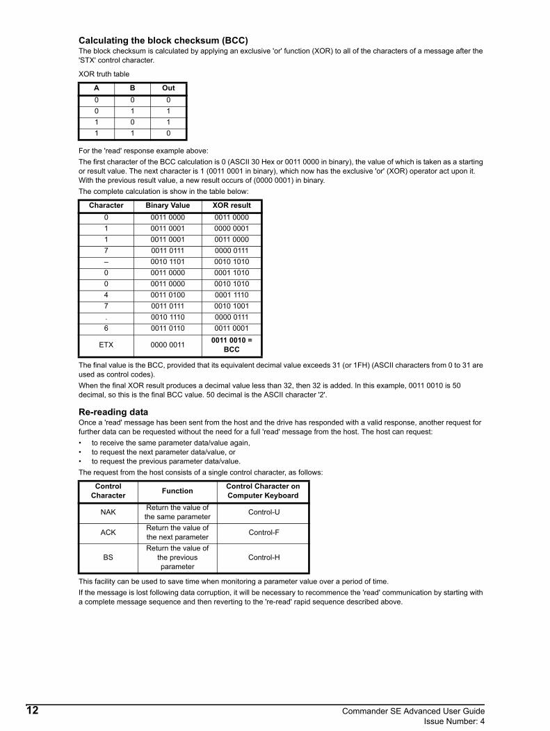
Calculating the block checksum (BCC)The block checksum is calculated by applying an exclusive 'or' function (XOR) to all of the characters of a message after the 'STX' control character.
XOR truth table
For the 'read' response example above:The first character of the BCC calculation is 0 (ASCII 30 Hex or 0011 0000 in binary), the value of which is taken as a starting or result value. The next character is 1 (0011 0001 in binary), which now has the exclusive 'or' (XOR) operator act upon it. With the previous result value, a new result occurs of (0000 0001) in binary.The complete calculation is show in the table below:
The final value is the BCC, provided that its equivalent decimal value exceeds 31 (or 1FH) (ASCII characters from 0 to 31 are used as control codes).When the final XOR result produces a decimal value less than 32, then 32 is added. In this example, 0011 0010 is 50 decimal, so this is the final BCC value. 50 decimal is the ASCII character '2'.
Re-reading dataOnce a 'read' message has been sent from the host and the drive has responded with a valid response, another request for further data can be requested without the need for a full 'read' message from the host. The host can request:• to receive the same parameter data/value again, • to request the next parameter data/value, or• to request the previous parameter data/value.The request from the host consists of a single control character, as follows:
This facility can be used to save time when monitoring a parameter value over a period of time.If the message is lost following data corruption, it will be necessary to recommence the 'read' communication by starting with a complete message sequence and then reverting to the 're-read' rapid sequence described above.
A B Out0 0 00 1 11 0 11 1 0
Character Binary Value XOR result0 0011 0000 0011 00001 0011 0001 0000 00011 0011 0001 0011 00007 0011 0111 0000 0111– 0010 1101 0010 10100 0011 0000 0001 10100 0011 0000 0010 10104 0011 0100 0001 11107 0011 0111 0010 1001. 0010 1110 0000 01116 0011 0110 0011 0001
ETX 0000 0011 0011 0010 = BCC
Control Character Function Control Character on
Computer Keyboard
NAK Return the value of the same parameter Control-U
ACK Return the value of the next parameter Control-F
BSReturn the value of
the previous parameter
Control-H
12 Commander SE Advanced User GuideIssue Number: 4

1.3.2 Writing DataTo write data (i.e. a value) to a drive parameter (i.e. host writing data to a drive), the message format from the host is as follows:
Where:CC = Control CharacterGA = Group addressGU = Unit address[M1][M2] = Menu number[P1] [P2] = Parameter number[D1][D2] ...[Dn] = Data characters including decimal point and sign where necessaryBCC = Block checksum (calculated as described below)
The data field can be of a variable length with a maximum length of 7 characters.Following the 'write' message, the drive will respond with a single control character, as follows:
An example of a host writing a value of +76.4 to parameter 1.25 of a drive that is addressed as unit 6 of group 2, the host message is:
The BCC in this example is calculated by the host as follows:
Calculating the block checksum (BCC)The block checksum is calculated by applying an exclusive 'or' function (XOR) to all of the characters of a message after the 'STX' control character.XOR truth table
For the 'write' message example above:The first character of the BCC calculation is 0 (0011 0000 in binary), the value of which is taken as a starting or result value. The next character is 1 (0011 0001 in binary), which now has the exclusive 'or' (XOR) operator act upon it. With the previous result value, a new result occurs of (0000 0001) in binary.The complete calculation is show in the table below:
The final value is the BCC, provided that its equivalent decimal value exceeds 31 (or 1FH) (ASCII characters from 0 to 31 are used as control codes).When the final XOR result produces a decimal value less than 32, then 32 is added. In this example, 0011 0101 is 53
CC Address CC Parameter Data CC BCCEOT GA GA UA UA STX M1 M2 P1 P2 D1 D2 .... Dn ETX BCC
Control Character Meaning
Control Character on Computer Keyboard
ASCII Character
NAK
Message invalid. Data is too long or out of range, parameter is invalid, parameter is read-only, or the BCC is incorrect.
Control-U
ACK Acknowledge — Message is valid and has been understood and implemented. Control-F
CC Address CC Parameter Data CC BCC
EOT 2 2 6 6 STX 0 1 2 5 + 7 6 . 4 ETX 5
A B Out0 0 00 1 11 0 11 1 0
Character Binary Value XOR result0 0011 0000 0011 00001 0011 0001 0000 00012 0011 0010 0011 00115 0011 0101 0000 0110+ 0010 1011 0010 11017 0011 0111 0001 10106 0011 0110 0010 1100. 0010 1110 0000 00104 0011 0100 0011 0110
ETX 0000 0011 0011 0101 = BCC
Commander SE Advanced User Guide 13Issue Number: 4

decimal, so this is the final BCC value. 53 decimal is the ASCII character '5'. The drive should reply with ACK control character if the message was received correctly, and the BCC agrees with the drive calculation.
1.3.3 Re-writing dataOnce a complete 'write' message has been sent to a drive, and the drive has responded with either a 'ACK' or 'NAK' character, subsequent 'write' messages to that particular drive can use a re-write message structure. The address does not need to be re-transmitted. The 're-write' message structure is as follows:
When a different drive needs to be addressed, or an ACK or NAK response is not received from the current drive addressed, the 're-write' facility can no longer be used. The particular drive can only be addressed by using the full 'write' message with the correct address, etc.
1.4 Modbus RTU1.4.1 Parameters
11.24 Serial Communication Mode
0 AnSI Ansi protocol half duplex serial communications 2 wire1 rtu Modbus RTU high data rate protocol2 F.bus Fieldbus communications mode
To implement Modbus RTU, parameter 11.24 should be set to 1
11.25 Data (baud) rate
0 2.4 2,400 bits/sec1 4.8 4,800 bits/sec2 9.6 9,600 bits/sec3 19.2 19,200 bits/sec
Used to select the communications port data (baud) rate.
11.23 Modbus node address
Used to define the network node address for the Commander SE. All nodes on a Modbus network MUST be configured with a unique node address.
1.4.2 Modbus frame specification
The COMMANDER SE does not use the parity bit.
1.4.3 Modbus register valueAll Commander SE parameters are mapped to the 4XXXX series of Modbus registers. To convert from a parameter number to a Modbus register, remove the decimal point from the parameter number e.g. parameter 11.22 = register 41122. All parameters (including bit parameters) are handled as signed 16 bit values.
1.4.4 Supported functions0x03 (3) Read holding registers Read Multiple Parameters0x10 (16) Preset multiple registers Write Multiple Parameters0x17 (23) Read/Write registers Read and Write Multiple ParametersWhen using multiple write or read commands, the parameters written to or read from must be consecutive. If a block of parameters is written to or read from where there is a missing parameter, the slave will respond with an exception code. Therefore this block should be split into a number of smaller blocks so as not to write to or read from a missing parameter.The maximum number of consecutive parameters that can be written to or read from is 16.
1.4.5 Broadcast messagesCommander SE also supports broadcast messages. If the master controller sends a WRITE message to node address 0, all nodes will accept the message but none will reply to the master.
CC Parameter Data CC BCCSTX M1 M2 P1 P2 D1 D2 .... Dn ETX BCC
Range Default Type Limitations Level 2 parameter0 ~ 2 0 (AnSi) RW P 41
Range Default Type Limitations Level 2 parameter0 ~ 3 1 (4.8) RW P 42
Range Default Type Limitations Level 2 parameter0.1 ~ 24.7 1.1 RW P 43
1 start bit 8 data bits 1 stop bit
14 Commander SE Advanced User GuideIssue Number: 4
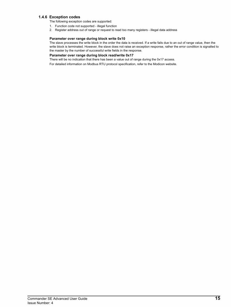
1.4.6 Exception codesThe following exception codes are supported:1. Function code not supported - illegal function2. Register address out of range or request to read too many registers - illegal data address
Parameter over range during block write 0x10The slave processes the write block in the order the data is received. If a write fails due to an out of range value, then the write block is terminated. However, the slave does not raise an exception response, rather the error condition is signalled to the master by the number of successful write fields in the response.Parameter over range during block read/write 0x17There will be no indication that there has been a value out of range during the 0x17 access.For detailed information on Modbus RTU protocol specification, refer to the Modicon website.
Commander SE Advanced User Guide 15Issue Number: 4

2 Parameter TypesThere are two fundamental types of parameters in the drive, read only (R/O) and read/write (R/W). The read only parameters cannot be changed by the user and are there to give the user useful information about the state of the drive. Read/write parameters are for the user to set up the way in which the drive operates.Parameters can be further broken down into Bit parameters and Non-bit parameters. Bit parameters are two state only (0 or 1) and if R/W are used as switches or two state input variables to the drive logic, or if R/O indicate various drive conditions which are either true (1) or false (0). Non-bit parameters have more than two values the range of each being given in the following descriptions.In the basic parameter set, some parameters are represented as strings rather than numeric values which give a more informative indication of the parameter setting.Since the parameters in the basic parameter set are copies of extended parameters, in the descriptions below the strings are indicated as well as the numeric value. Setting up via the serial interface requires numeric data.Most parameters when being adjusted take immediate effect, but there are some which do not. These are generally parameters which could cause a malfunction in the operation of the drive if an intermediary value were taken during the adjustment, such as parameters defining the destination of programmable inputs. For the new value of one of these parameters to take effect a 'Drive Reset' must be carried out (see below). Parameters which require a 'Drive Reset' before any new value becomes effective are coded with an R in the following descriptions.Any changes made to parameters over the serial interface are not stored in the drives EEPROM until a manual store is initiated.It will be seen later that Bit parameters can be controlled by programmable logic inputs or internal logic functions, and Non-bit parameters can be controlled by programmable analog inputs or internal drive functions. However, some parameters are of such a sensitive nature that they are protected from being controlled by programmable inputs and functions and these are coded with a P in the following descriptions.
2.1 Drive ResetA drive reset is required for a number of reasons:• To reset the drive from a tripped state• To initiate loading of defaults• To implement a change in the value of certain parameters• To initiate the saving of parameters in EEPROMThe later two of these can be carried out while the drive is running.The drive can be reset in one of four ways:• The drive will be reset with a 0 to 1 transition of the drive enable when the drive is tripped, such that a dedicated reset
terminal is not required.• The drive will be reset when a 0 to 1 transition of the Drive Reset parameter (10.33). This parameter is provided for
control by a programmable digital input such that a terminal can be used to reset the drive.• The Stop/Reset key. If the drive is not in keypad mode and the 'always stop' parameter is not set, then the key has a drive
reset function only. In keypad mode or if the 'always stop' parameter is set, a drive reset can be carried out while the drive is running by holding the Run key while the Stop/Reset key is activated. When the drive is not running the Stop/Reset key will always reset the drive.
• By the serial interface. This drive reset is triggered by a value of 100 being written to the User trip parameter (10.38).
2.2 Storing drive parametersUsing SE Soft:• Go to 'Tools' on tool bar• Click on 'Save parameters in drive'• Click on 'OK drive reset - parameters saved' box when prompted - OR• Go to 'Compare and Menu Tables'• Select 'Menu 1' (or any other Menu)• Set 01.00 (or xx.00) to 1000 and perform a RESET as above
Using Universal keypad:Set any Menu zero parameter, parameter xx.00 to 1000 and perform a RESET as above or:• Press the red STOP/RESET key on the Universal keypad (if enabled)
2.3 Key to parameter codesRW Read/WriteRO Read OnlyBit Two state only parameter, 0 or 1Bi Bipolar - can have positive and negative valuesUni Unipolar - can have positive values onlyTxt Parameter value is represented on the display with strings of Text.R Requires a 'Drive Reset' before any new value will be implementedP Parameter is Protected from being controlled by programmable inputs and functionsS Parameter saved on power down
16 Commander SE Advanced User GuideIssue Number: 4

3 MenusThe following table gives a list of level 1 and level 2 parameters and their corresponding extended menu parameter(s).
* Only becomes active when parameter 29 is set to “br.Eu” or “br.US” and the STOP/RESET button is pressed for 1 second.
Par DescriptionDefault Corresponding
extended menu parameter
Level 1 and 2 setting
Update rateEUR USA
LEVEL 101 Min. speed (Hz) 0.0 1.07 B02 Max. speed (Hz) 50.0 60.0 1.06 B03 Accel. rate (s/100Hz) 5.0 2.11 L204 Decel. rate (s/100Hz) 10.0 2.21 L205 Ref. select A1.A2 PAd 1.14 L206 Motor rated current (A) Drive rating 5.07 BS, MC07 Motor rated speed (rpm) 1500 1800 5.08 BS, MC08 Motor rated voltage (V) 230 / 400 230 / 460 5.09 BF, MC09 Motor power factor 0.85 5.10 BF, MC10 Parameter access L1 L1 11.44 B
LEVEL 211 Preset 1 (Hz) 0.0 1.21 L212 Preset 2 (Hz) 0.0 1.22 L213 Preset 3 (Hz) 0.0 1.23 L214 Preset 4 (Hz) 0.0 1.24 L215 Jog. speed (Hz) 1.5 1.05 L216 Current mode (mA) 4-.20 7.11 L217 Enable negative preset speeds OFF 1.10 B18 Last trip -- 10.20 B19 Trip before parameter 18 -- 10.21 B20 Trip before parameter 19 -- 10.22 B21 Trip before parameter 20 -- 10.23 B22 Load display units Ld 4.21 B23 Speed display units Fr 5.34 B24 Customer scaling 1.00 11.21 B25 Security setup 0 11.30 B26 Fwd/rev key enable OFF 6.13 L127 Power up key. ref 0 1.51 I28 Parameter cloning no 11.42 B29 Load defaults no 11.43 B30 Ramp mode 1 2.04 B31 Stopping mode 1 6.01 L132 Variable torque select OFF 5.13 BS, MC33 Spinning motor select 0 6.09 B34 Positive logic select On 8.29 I35 Start/Stop logic select 0 6.04 B, I36 Analog output select Fr 7.33 B37 Switching frequency (kHz) 6 5.18 B38 Auto tune 0 5.12 B39 Rated frequency (Hz) 50.0 60.0 5.06 BS, MC40 No. of poles Auto 5.11 BS, MC41 Serial mode AnSI 11.24 BF, L142 Baud rate 4.8 11.25 BF43 Serial address 1.1 11.23 BF44 Software version -- 11.29 I45 Fieldbus node address 0 15.0346 Fieldbus baudrate 0 15.0447 Fieldbus diagnostics 0 15.0648 Voltage mode selector 3 5.14 BS,MC49 Low frequency voltage boost 3.0 5.15 BF,MC50 Motor thermistor select OFF 8.40 LI*51 Zero speed threshold 1.0 3.05 B*52 Motor current threshold 0 4.01 B*53 Motor current threshold 0 12.05 L3*54 Brake release delay time 0 9.09 L3
Commander SE Advanced User Guide 17Issue Number: 4

3.1 Menu 1: Speed reference selection, limits and filters
* The maximum value is 1.06 or 21.01.
Parameter Range Type Default Setting Update Rate
1.01 Level of reference selected ±1000.0 Hz* RO Bi P L21.02 Pre-filter reference ±Max RO Bi P L21.03 Pre-ramp reference ±Max RO Bi P L21.04 Not used1.05 Jog reference 0 ~ 400.0Hz RW Uni 1.5 L2
1.06 Maximum speed clamp 0 ~1000.0Hz RW Uni 50(EUR)60(USA) B
1.07 Minimum speed clamp 0 ~ [1.06] RW Uni 0.0 B1.08~1.09 Not used
1.10 Allow negative digital references 0 or 1 RW Bit 0 B1.11 Reference enabled indicator 0 or 1 RO Bit P L11.12 Reverse selected indicator 0 or 1 RO Bit P L11.13 Jog selected indicator 0 or 1 RO Bit P L1
1.14 Reference selector 0-5 RW Uni Txt 0(EUR)4(USA) L2
1.15 Preset selector 0-8 RW Uni 0 L21.16 Not used1.17 Keypad reference ±Max RO Bi S P 0.0 B1.18 Precision reference ±1000.0Hz RW Bi 0.0 L21.19 Precision reference trim 0 ~ 99mHz RW Uni 0 L21.20 Precision reference update disable 0 or 1 RW Bit 0 L21.21 Preset speed reference 1 ±1000.0Hz RW Bi 0.0 L21.22 Preset speed reference 2 ±1000.0Hz RW Bi 0.0 L21.23 Preset speed reference 3 ±1000.0Hz RW Bi 0.0 L21.24 Preset speed reference 4 ±1000.0Hz RW Bi 0.0 L21.25 Preset speed reference 5 ±1000.0Hz RW Bi 0.0 L21.26 Preset speed reference 6 ±1000.0Hz RW Bi 0.0 L21.27 Preset speed reference 7 ±1000.0Hz RW Bi 0.0 L21.28 Preset speed reference 8 ±1000.0Hz RW Bi 0.0 L21.29 Skip frequency 1 0 ~1000.0Hz RW Uni 0.0 B1.30 Skip frequency band 1 0 ~ 5.0Hz RW Uni 0.5 B1.31 Skip frequency 2 0 ~1000.0Hz RW Uni 0.0 B1.32 Skip frequency band 2 0 ~ 5.0Hz RW Uni 0.5 B1.33 Skip frequency 3 0 ~1000.0Hz RW Uni 0.0 B1.34 Skip frequency band 3 0 ~ 5.0Hz RW Uni 0.5 B1.35 Reference in skip frequency band indicator 0 or 1 RO Bit P L21.36 Analog reference 1 ±1000Hz* RO Bi L21.37 Analog reference 2 ±1000Hz* RO Bi L21.38~1.40 Not used
1.41 Analog reference 2 select 0 or 1 RO Bit L21.42 Preset reference select 0 or 1 RO Bit L21.43 Keypad reference select 0 or 1 RO Bit L21.44 Precision reference select 0 or 1 RO Bit L21.45 Preset select bit 0 0 or 1 RO Bit L21.46 Preset select bit 1 0 or 1 RO Bit L21.47 Preset select bit 2 0 or 1 RO Bit L21.48 Not used1.49 Reference selected indicator 1 ~ 5 RO Uni P L21.50 Preset selected indicator 1 ~ 8 RO Uni P L21.51 Power up keypad reference 0 ~ 2 RW Uni Txt 0 I
18 Commander SE Advanced User GuideIssue Number: 4

Indication of the reference being used by the drive is given for system setup and fault finding.
Indication of the reference being used by the drive is given for system setup and fault finding.
Speed reference used for jogging.
This parameter is a symmetrical limit on both directions of rotation.Defines drive absolute maximum frequency reference. Slip compensation and current limit can increase the motor frequency further.
Used in unipolar mode to define drive minimum speed. This can be overridden by maximum speed clamp 1.06 if adjusted to be less than 1.07. Inactive during jogging.
Needs to be set if the user requires to change the direction of rotation with a negative reference. If it is not set, all negative references are treated as zero.Possible negative references are:• Preset speeds 1 to 8• Keypad reference• Precision reference
Both analog inputs are unipolar and setting this bit does not allow bipolar analog references to be applied to the drive. If an analog bipolar reference is required, use the optional SE51 Bipolar Speed Reference PCB.
1.01 Level of reference selected
±1000.0 Hz RO Bi P
1.02 Pre-filter reference
1.03 Pre-ramp reference
±par 1.06 or ±par 21.01 Hz RO Bi P
1.04 Unused parameter
1.05 Jog reference
0 ~ 400.0 1.5 Hz RW Uni
1.06 Maximum speed clamp
0 ~ 1000.0EUR> 50.0
USA> 60.0Hz RW Uni
1.07 Minimum speed clamp
0 ~ parameter 1.06 0.0 Hz RW Uni
1.08~ 1.09 Unused parameters
1.10 Allow negative digital references
0 or 1 0 RW Bit
NOTE
Commander SE Advanced User Guide 19Issue Number: 4

These flags are controlled by the drive sequencer defined in Menu 6. They select the appropriate reference as commanded by the drive logic.
This parameter is used to select a speed reference for motor 1 as follows:0 A1.A2 Analog voltage input on terminal 2 and analog current input on terminal 5 selected by terminal 12. Jog
selected by terminal 13.1 A1.Pr Analog voltage input on terminal 2 and three preset speeds selected by terminals 12 and 13.2 A2.Pr Analog current input on terminal 5 and three preset speeds selected by terminals 12 and 13.3 Pr 4 preset speeds selected by terminals 12 and 13.4 PAd Keypad Control.5 PrC Precision reference
Automatic set-upAs parameter 05 is changed from A1.A2 to A1.Pr etc. through the drives keypad, parameter 1.14 will change accordingly as per the table below.Also the destination parameters of terminals 12 and 13 will change accordingly as long as 8.39 = 0 - automatic set-up is enabled.
PrC cannot be selected from parameter 05 through the drives keypad although it will be displayed if parameter 1.14 is set to 5.
Advanced set-upWhen 1.14 is set to 0, the reference selected can also depend on the state of bit parameters 1.41 to 1.44. These bits are controlled by digital inputs such that references can be selected by external control. If any of the bits are set, the appropriate reference is selected (indicated by 1.49). If more than 1 bit is set the highest number will have priority.
In analog reference 1 and analog reference 2 modes, a preset speed will be selected instead of analog reference 1 or analog reference 2 if the preset speed selected is any other than preset speed 1 even if the preset reference, 1.42, is not selected. This is because of the easy set-up modes that give the user the flexibility to select between analog reference 1 and 3 preset speeds, or analog reference 2 and 3 presets speed with only 2 digital inputs.
1.11 Reference enabled indicator
1.12 Reverse selected indicator
1.13 Jog selected indicator
0 or 1 RO Bit P
1.14 Reference selector
0 ~ 5EUR> 0
USA> 4RW Uni Txt
Parameter 05 Parameter 1.14 Terminal 12 destination
Terminal 13 destination Parameter 1.49
A1.A2 0 1.41 6.31 1A1.Pr 1 1.45 1.46 1A2.Pr 2 1.45 1.46 2
Pr 3 1.45 1.46 3PAd 4 4PrC 5 5
Parameter 1.41
Parameter 1.42
Parameter 1.43
Parameter 1.44
Frequency reference selected
Parameter 1.49
0 0 0 0 Analog reference 1 (A1) 11 0 0 0 Analog reference 2 (A2) 2x 1 0 0 Preset reference (Pr) 3x x 1 0 Keypad reference (PAd) 4x x x 1 Precision reference (Prc) 5
NOTE
NOTE
20 Commander SE Advanced User GuideIssue Number: 4
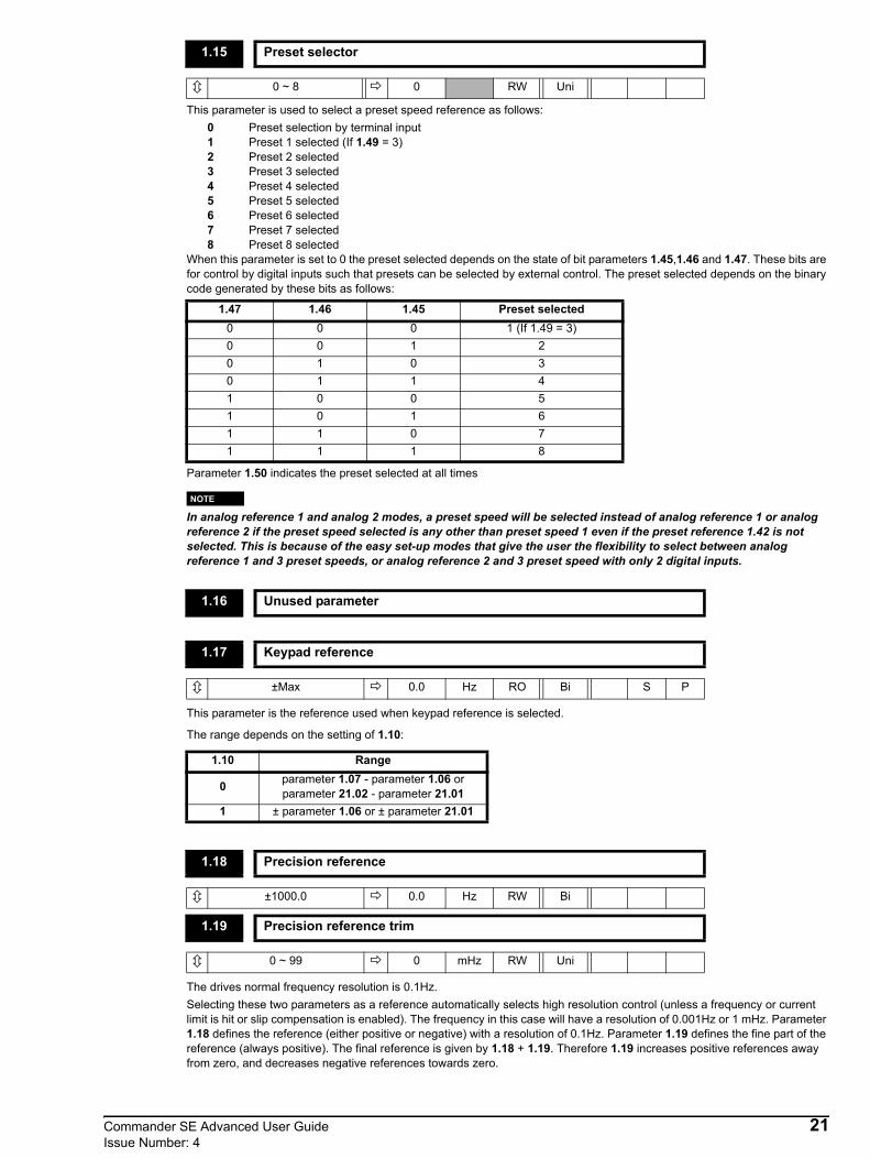
This parameter is used to select a preset speed reference as follows:0 Preset selection by terminal input1 Preset 1 selected (If 1.49 = 3)2 Preset 2 selected3 Preset 3 selected4 Preset 4 selected5 Preset 5 selected6 Preset 6 selected7 Preset 7 selected8 Preset 8 selected
When this parameter is set to 0 the preset selected depends on the state of bit parameters 1.45,1.46 and 1.47. These bits are for control by digital inputs such that presets can be selected by external control. The preset selected depends on the binary code generated by these bits as follows:
Parameter 1.50 indicates the preset selected at all times
In analog reference 1 and analog 2 modes, a preset speed will be selected instead of analog reference 1 or analog reference 2 if the preset speed selected is any other than preset speed 1 even if the preset reference 1.42 is not selected. This is because of the easy set-up modes that give the user the flexibility to select between analog reference 1 and 3 preset speeds, or analog reference 2 and 3 preset speed with only 2 digital inputs.
This parameter is the reference used when keypad reference is selected.
The range depends on the setting of 1.10:
The drives normal frequency resolution is 0.1Hz.Selecting these two parameters as a reference automatically selects high resolution control (unless a frequency or current limit is hit or slip compensation is enabled). The frequency in this case will have a resolution of 0.001Hz or 1 mHz. Parameter 1.18 defines the reference (either positive or negative) with a resolution of 0.1Hz. Parameter 1.19 defines the fine part of the reference (always positive). The final reference is given by 1.18 + 1.19. Therefore 1.19 increases positive references away from zero, and decreases negative references towards zero.
1.15 Preset selector
0 ~ 8 0 RW Uni
1.47 1.46 1.45 Preset selected0 0 0 1 (If 1.49 = 3)0 0 1 20 1 0 30 1 1 41 0 0 51 0 1 61 1 0 71 1 1 8
1.16 Unused parameter
1.17 Keypad reference
±Max 0.0 Hz RO Bi S P
1.10 Range
0 parameter 1.07 - parameter 1.06 or parameter 21.02 - parameter 21.01
1 ± parameter 1.06 or ± parameter 21.01
1.18 Precision reference
±1000.0 0.0 Hz RW Bi
1.19 Precision reference trim
0 ~ 99 0 mHz RW Uni
NOTE
Commander SE Advanced User Guide 21Issue Number: 4

When this bit is at 0 the precision reference parameters are read and stored in internal memory. Because the precision reference has to be set in two parameters, this bit is provided to prevent the drive reading the parameters while the reference is being updated. Instead, the drive uses the value stored in memory thus preventing the possibility of data skew.
Preset speed references 1 to 8.
Three skip frequency's available to prevent mechanical resonance's in a system by ensuring that certain frequencies are avoided by always ramping through them. When a skip frequency parameter is set to 0 that filter is disabled.
The skip frequency band parameters define the frequency either side of the programmed skip frequency, over which references are rejected. The actual reject band is therefore twice that programmed in these parameters, the skip frequency parameters defining the centre of the band. When the selected reference is within a band the lower limit of the band is passed through to the ramps such that speed is always less than demanded.
This parameter indicates that the selected reference is within one of the skip frequency regions such that the motor speed is not as demanded.
1.20 Precision reference update disable
0 or 1 0 RW Bit
1.21 Preset speed reference 1
1.22 Preset speed reference 2
1.23 Preset speed reference 3
1.24 Preset speed reference 4
1.25 Preset speed reference 5
1.26 Preset speed reference 6
1.27 Preset speed reference 7
1.28 Preset speed reference 8
±1000.0 0.0 Hz RW Bi
1.29 Skip frequency 1
1.31 Skip frequency 2
1.33 Skip frequency 3
0 ~ 1000.0 0.0 Hz RW Uni
1.30 Skip frequency band 1
1.32 Skip frequency band 2
1.34 Skip frequency band 3
0 ~ 5.0 0.5 Hz RW Uni
1.35 Reference in skip frequency band indicator
0 or 1 RO Bit P
22 Commander SE Advanced User GuideIssue Number: 4

These parameters are made available for control by analog inputs which are required to be frequency references.The programmed input is automatically scaled such that 100.0% input corresponds to the set maximum speed (1.06 or 21.01). Also the 0% input level corresponds to the minimum speed level (1.07 or 21.02) if Allow negative digital references (1.10) is not selected.
Although the drive’s analog inputs (7.01, 7.02) cannot provide negative speed references, if the analog input destination parameters (7.10, 7.14) are directed away from the analog reference parameters (1.36, 1.37), then negative values can be written to them over the serial interface.
These bits are provided for control by logic input terminals for external reference selection (see parameters 1.14, 21.03 and 1.15).
Although parameters 1.41 to 1.47 are Read only parameters, they can be written to but only via a digital input.
1.36 Analog reference 1
1.37 Analog reference 2
±par 1.06 or ±par 21.01 Hz RO Bi
1.38 ~ 1.40 Unused parameters
1.41 Analog reference 2 select
1.42 Preset reference select
1.43 Keypad reference select
1.44 Precision reference select
1.45 Preset select bit 0
1.46 Preset select bit 1
1.47 Preset select bit 2
0 or 1 RO Bit
Allow negative digital reference operation
(01.10 = 1)Frequency1.06
100.0Input (%)
0
NOTE
Commander SE Advanced User Guide 23Issue Number: 4

Indicates the reference currently being selected.1 Analog reference 1 selected2 Analog reference 2 selected3 Preset reference selected4 Keypad reference selected5 Precision reference selected
Indicates the preset currently being selected. If 1.49 = 1 or 2 then a value of 1 indicates that one of the analog references is being selected.
Selects the value of the keypad reference on power-up.0 0 keypad reference is zero1 LASt keypad reference is the last used value2 PrS1 keypad reference is copied from preset speed 1 (parameter 1.21)
1.48 Unused parameter
1.49 Reference selected indicator
1 ~ 5 RO Uni P
1.50 Preset selected indicator
1 ~ 8 RO Uni P
1.51 Power-up keypad reference
0 ~ 2 0 RW Uni Txt
24 Commander SE Advanced User GuideIssue Number: 4

Jog
refe
renc
e 1
.05
01
1
0
1.0
1
Ref
eren
ce s
elec
ted
1 0
Max
spee
d 1
.06
Min
spee
d 1
.07
Max
spee
d 2
1.01
* M
in sp
eed
21.
02 *
Dis
able
Min
spee
d
Rev
erse
sele
ct R
efer
ence
O
n
1 0
1.1
3 1
.12
1.1
1
0 H
z
OR
D
rive
Sequ
ence
r M
enu
6
M
enu
8
Pre
set 1
1.2
1
Pre
set 2
1.2
2
Pre
set 3
1.2
3
Pre
set 4
1.2
4
Pre
set 5
1.2
5
Pre
set 6
1.2
6
Pre
set 7
1.2
7
Pre
set 8
1.2
8
Key
pad
refe
renc
e 1
.17
Pre
cisi
on re
fere
nce
1.1
8 &
1.1
9
Ana
log
refe
renc
e 1
1.36
1.37
1
2 3
Pre
cisi
on re
fere
nce
u
pdat
e di
sabl
e
1
.20
1
2 3 4 5 6 7 8 M
emor
y
01
1 - 3 4
5
Pre
set r
efer
ence
sele
cted
indi
cato
r
1.
50
M E N U 7
2 5
L O G I C
01
to 8
Pre
set r
efer
ence
sel
ecto
r 1
.15
1.15
= 0
, ref
. sel
ecte
d by
dig
ital i
nput
s1.
15 =
1-8
, ref
. sel
ecte
d by
setti
ng o
f 1.1
5
Ref
eren
ce se
lect
edin
dica
tor
1
.49
Pres
et se
lect
0
1.45
Pres
et se
lect
1
1.46
Pres
et se
lect
2
1.47
M E N U 8
Prio
rity
01
to 5
Ref
eren
ce se
lect
or
1.1
41.
14 =
0, r
ef. s
elec
ted
by d
igita
l inp
uts
1.14
= 1
-5, r
ef. s
elec
ted
by se
tting
of 1
.14
Ref
eren
ce se
lect
or 2
1.03
*(a
s 1.1
4)
An.
ref 2
sele
ct
1.4
1
Pres
et se
lect
1
.42
Key
pad
sele
ct
1.43
Prec
.ref s
elec
t
1.44
L O G I C
Ana
log
refe
renc
e 2
X -
1
D I G I T A L I N P U T S
DIG
ITA
L IN
PUTS
Ski
p fr
eque
ncy
1 1
.29
Ski
p ba
nd 1
1
.30
Ski
p fr
eque
ncy
2 1
.31
Ski
p ba
nd 2
1
.32
Ski
p fr
eque
ncy
3 1
.33
Ski
p ba
nd 3
1
.34
1.0
2
Pre-
filte
rre
fere
nce
In fi
lter z
one
1.0
3
Pre-
ram
pre
fere
nce
1.3
5
* In
dica
tes p
aram
eter
from
seco
nd m
otor
mot
or m
ap
Pow
er u
p k
eypa
d re
f
1.5
1
0
Last
0
12
Men
u 2
MEN
U 1
Spee
d re
fere
nce
sele
ctio
n,lim
its a
nd fi
lters
Allo
w n
egat
ive
digi
tal
refe
renc
es1.
10
Jog
sele
ct
Commander SE Advanced User Guide 25Issue Number: 4

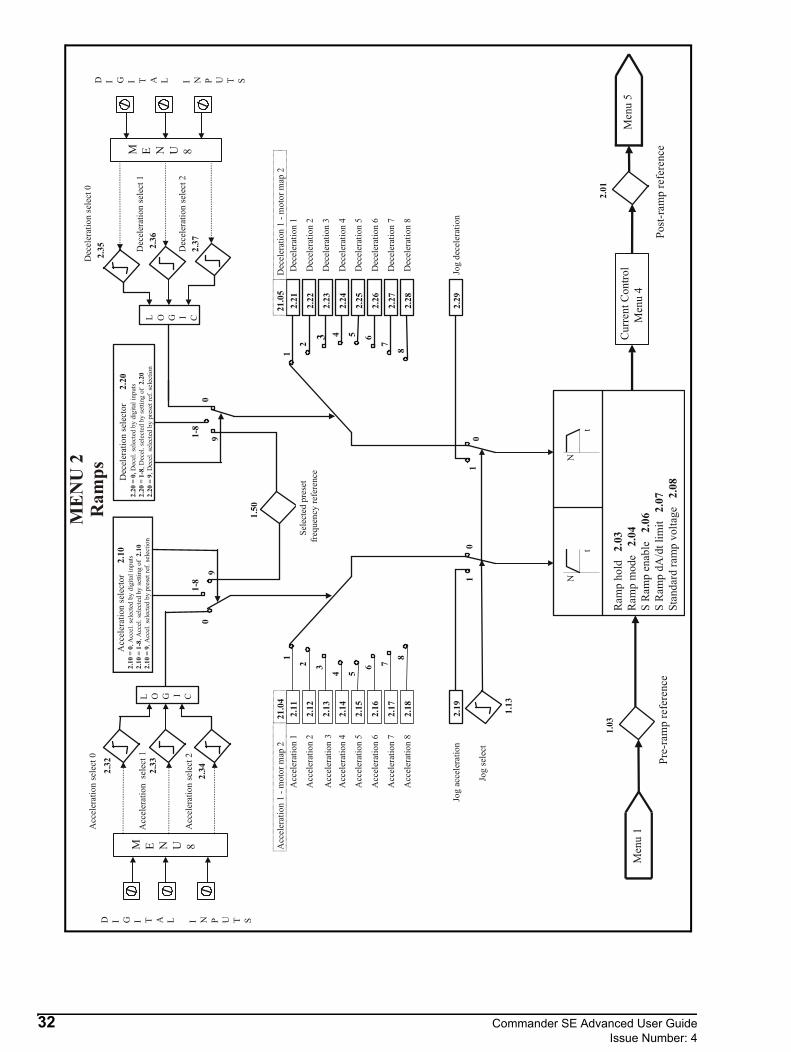
3.2 Menu 2: Ramps
Parameter Range Type Default Setting Update Rate
2.01 Post ramp speed reference ±Max RO Bi P L32.02 Not used2.03 Ramp hold 0 or 1 RW Bit 0 I, L12.04 Ramp mode selector 0 ~ 2 RW Uni 1 (Std) B2.05 Not used2.06 S-ramp enable 0 or 1 RW Bit 0 B2.07 S-ramp maximum da/dt 0.1 ~ 3000s²/100Hz RW Uni 3.1 B
2.08 Standard ramp voltage 400V drive = 0~800 200V drive = 0~400 RW Uni
400V drive = 750 (EUR) 775 (USA)200V drive = 390
B
2.09 Not used2.10 Acceleration ramp selector 0-9 RW Uni 0 L22.11 Acceleration rate 1 0.1~3200.0s/100Hz RW Uni 5.0 L22.12 Acceleration rate 2 0.1~3200.0s/100Hz RW Uni 5.0 L22.13 Acceleration rate 3 0.1~3200.0s/100Hz RW Uni 5.0 L22.14 Acceleration rate 4 0.1~3200.0s/100Hz RW Uni 5.0 L22.15 Acceleration rate 5 0.1~3200.0s/100Hz RW Uni 5.0 L22.16 Acceleration rate 6 0.1~3200.0s/100Hz RW Uni 5.0 L22.17 Acceleration rate 7 0.1~3200.0s/100Hz RW Uni 5.0 L22.18 Acceleration rate 8 0.1~3200.0s/100Hz RW Uni 5.0 L22.19 Jog acceleration rate 0.1~3200.0s/100Hz RW Uni 0.2 L22.20 Deceleration ramp selector 0 ~ 9 RW Uni 0 L22.21 Deceleration rate 1 0.1~3200.0s/100Hz RW Uni 10.0 L22.22 Deceleration rate 2 0.1~3200.0s/100Hz RW Uni 10.0 L22.23 Deceleration rate 3 0.1~3200.0s/100Hz RW Uni 10.0 L22.24 Deceleration rate 4 0.1~3200.0s/100Hz RW Uni 10.0 L22.25 Deceleration rate 5 0.1~3200.0s/100Hz RW Uni 10.0 L22.26 Deceleration rate 6 0.1~3200.0s/100Hz RW Uni 10.0 L22.27 Deceleration rate 7 0.1~3200.0s/100Hz RW Uni 10.0 L22.28 Deceleration rate 8 0.1~3200.0s/100Hz RW Uni 10.0 L22.29 Jog deceleration rate 0.1~3200.0s/100Hz RW Uni 0.2 L22.30~ 2.31 Not used
2.32 Acceleration select bit 0 (LSB) 0 or 1 RO Bit 0 L22.33 Acceleration select bit 1 0 or 1 RO Bit 0 L22.34 Acceleration select bit 2 (MSB) 0 or 1 RO Bit 0 L22.35 Deceleration select bit 0 (LSB) 0 or 1 RO Bit 0 L22.36 Deceleration select bit 1 0 or 1 RO Bit 0 L22.37 Deceleration select bit 2 (MSB) 0 or 1 RO Bit 0 L2
26 Commander SE Advanced User GuideIssue Number: 4

This is the speed reference after the ramps. For analog output scaling, the range of this parameter is ±1.06 or ±21.01.
If this bit is set the ramp will be held.
This parameter has 3 settings as follows:0 Fast ramp1 Standard ramp with normal motor voltage2 Standard ramp with high motor voltage
The acceleration ramp is not affected by the ramp mode, and the ramp output will rise at the programmed acceleration rate (subject to the current limits programmed). In mode 0 the output of the ramp will also fall at the programmed deceleration rate (subject to the current limits programmed).
Mode 0 should be selected when using a braking resistor.
In modes 1 & 2 the voltage rising to the standard ramp level (2.08) causes a proportional controller to operate, the output of which changes the demanded current in the motor. As the controller regulates the DC Bus voltage, the motor deceleration increases as the speed approaches zero speed. When the motor deceleration rate reaches the programmed deceleration rate the controller ceases to operate and the drive continues to decelerate at the programmed rate. If the standard ramp voltage (2.08) is set lower than the nominal DC Bus level the drive will not decelerate but will coast to rest.The current demand is fed to the frequency changing current controller and therefore the gain parameters 4.13 and 4.14 must be set up for optimum control.In mode 1 the motor voltage is correctly set according to the motor rated voltage parameter, while in mode 2 the motor voltage is allowed to go up to a factor of 1.2 times its normal value during deceleration. This second mode saturates the motor which increases the losses and therefore reduces the amount of energy transferring from the motor to the DC Bus for a given deceleration rate. For a given amount of energy being dissipated by the drive at the regulated DC Bus level, mode 2 will allow a faster deceleration than mode 1, providing that the motor can stand the extra losses being dissipated in it.See section 12.28 Ramp Modes on page 193 for further details.
Setting this parameter enables the S-ramp function. The S-ramp is disabled if the standard ramp controller is activated during ramp modes 1 and 2 (2.04).
This parameter defines the maximum rate of change of acceleration that the drive will operate with.The default values have been chosen such that for the default ramps and maximum speed, the curved parts of the S will be 25% of the original ramp if S-ramp is enabled.
2.01 Post ramp speed reference
±par 1.06 or ±par 21.01 Hz RO Bi P
2.02 Unused parameter
2.03 Ramp hold
0 or 1 0 RW Bit
2.04 Ramp mode selector
0 ~ 2 1 RW Uni
2.05 Unused parameter
2.06 S-ramp enable
0 or 1 0 RW Bit
2.07 S-ramp maximum da/dt
0.1 ~ 3000.0 3.1 s2/100Hz RW Uni
NOTE
Commander SE Advanced User Guide 27Issue Number: 4

Since the ramp rate is defined in s/100Hz and the S ramp parameter is defined in s2/100Hz, the time T for the 'curved' part of the S can be determined quite easily by dividing the two variables thus:
T = S-ramp rate of change / Ramp rateEnabling S-ramp increases the total ramp time by the period T since an additional T/2 is added to each end of the ramp in producing the S.
Although the ramp rate can be set to 0.0, there is a minimum ramp time within the software of 0.1s/100Hz.
This voltage is used as the level for standard ramp modes. If it is set too low the machine will coast to rest, and if it is set too high and no braking resistor is used it may trip on OV. The minimum level should be greater than the voltage produced on the DC Bus by the highest supply voltage. Normally the DC Bus voltage will be approximately the rms supply voltage x √2.
Care should be taken in the setting of this parameter. It is recommended that the setting should be at least 50V higher than the maximum expected level of the DC Bus voltage. If this is ignored, the motor may fail to decelerate on a STOP command.
This parameter is used to select acceleration ramp rates as follows:0 Ramp rate selection by terminal input1 Ramp rate 1 selected2 Ramp rate 2 selected3 Ramp rate 3 selected4 Ramp rate 4 selected5 Ramp rate 5 selected6 Ramp rate 6 selected7 Ramp rate 7 selected8 Ramp rate 8 selected9 Ramp rate selection by preset reference selection
When parameter 2.10 is set to 0 the acceleration ramp rate selected depends on the state of bit parameters 2.32, 2.33 & 2.34. These bits are for control by digital inputs such that ramp rates can be selected by external control. The ramp rate selected depends on the binary code generated by these bits as follows:
2.08 Standard ramp voltage
400V drive: 0 ~ 800
200V drive: 0 ~ 400
400V drive: 750 (Eur) 775 (USA)200V drive: 390
RW Uni
t
AccelerationActual Speed
Programmedramp rate
T TT/2 T/2 T/2T/2
S rampaccelerationrate of change
Demanded Speed
NOTE
2.09 Unused parameter
2.10 Acceleration ramp selector
0 ~ 9 0 RW Uni
CAUTION
28 Commander SE Advanced User GuideIssue Number: 4
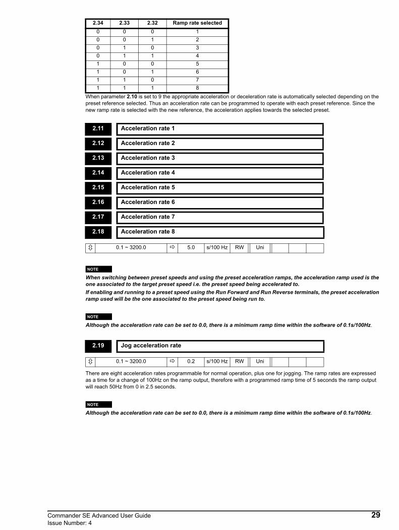
When parameter 2.10 is set to 9 the appropriate acceleration or deceleration rate is automatically selected depending on the preset reference selected. Thus an acceleration rate can be programmed to operate with each preset reference. Since the new ramp rate is selected with the new reference, the acceleration applies towards the selected preset.
When switching between preset speeds and using the preset acceleration ramps, the acceleration ramp used is the one associated to the target preset speed i.e. the preset speed being accelerated to.If enabling and running to a preset speed using the Run Forward and Run Reverse terminals, the preset acceleration ramp used will be the one associated to the preset speed being run to.
Although the acceleration rate can be set to 0.0, there is a minimum ramp time within the software of 0.1s/100Hz.
There are eight acceleration rates programmable for normal operation, plus one for jogging. The ramp rates are expressed as a time for a change of 100Hz on the ramp output, therefore with a programmed ramp time of 5 seconds the ramp output will reach 50Hz from 0 in 2.5 seconds.
Although the acceleration rate can be set to 0.0, there is a minimum ramp time within the software of 0.1s/100Hz.
2.34 2.33 2.32 Ramp rate selected0 0 0 10 0 1 20 1 0 30 1 1 41 0 0 51 0 1 61 1 0 71 1 1 8
2.11 Acceleration rate 1
2.12 Acceleration rate 2
2.13 Acceleration rate 3
2.14 Acceleration rate 4
2.15 Acceleration rate 5
2.16 Acceleration rate 6
2.17 Acceleration rate 7
2.18 Acceleration rate 8
0.1 ~ 3200.0 5.0 s/100 Hz RW Uni
2.19 Jog acceleration rate
0.1 ~ 3200.0 0.2 s/100 Hz RW Uni
NOTE
NOTE
NOTE
Commander SE Advanced User Guide 29Issue Number: 4

This parameter is used to select deceleration ramp rates as follows:0 Ramp rate selection by terminal input1 Ramp rate 1 selected2 Ramp rate 2 selected3 Ramp rate 3 selected4 Ramp rate 4 selected5 Ramp rate 5 selected6 Ramp rate 6 selected7 Ramp rate 7 selected8 Ramp rate 8 selected9 Ramp rate selection by preset reference selection
When 2.20 is set to 0 the deceleration ramp rate selected depends on the state of bit parameters 2.35, 2.36 & 2.37. These bits are for control by digital inputs such that ramp rates can be selected by external control. The ramp rate selected depends on the binary code generated by these bits as follows:
When 2.20 is set to 9 the appropriate deceleration rate is automatically selected depending on the preset reference selected. Thus an deceleration rate can be programmed to operate with each preset reference. Since the new ramp rate is selected with the new reference, the deceleration applies towards the selected preset.
When switching between preset speeds and using the preset deceleration ramps, the deceleration ramp used is the one associated to the target preset speed i.e. the preset speed being decelerated to.
Although the deceleration rate can be set to 0.0, there is a minimum ramp time within the software of 0.1s/100Hz.
2.20 Deceleration ramp selector
0 ~ 9 0 RW Uni
2.35 2.36 2.37 Ramp rate selected0 0 0 10 0 1 20 1 0 30 1 1 41 0 0 51 0 1 61 1 0 71 1 1 8
2.21 Deceleration rate 1
2.22 Deceleration rate 2
2.23 Deceleration rate 3
2.24 Deceleration rate 4
2.25 Deceleration rate 5
2.26 Deceleration rate 6
2.27 Deceleration rate 7
2.28 Deceleration rate 8
0.1 ~ 3200.0 10 s/100 Hz RW Uni
NOTE
NOTE
30 Commander SE Advanced User GuideIssue Number: 4

There are eight deceleration rates programmable for normal operation, plus one for jogging. The ramp rates are expressed as a time for a change of 100Hz on the ramp output, therefore, with a programmed ramp time of 10 seconds the ramp output will decelerate from 50Hz to 0Hz in 5 seconds.
Although the deceleration rate can be set to 0.0, there is a minimum ramp time within the software of 0.1s/100Hz.
These bits are provided for control by logic input terminals for external ramp selection (see 2.10 & 2.20).
2.29 Jog deceleration rate
0.1 ~ 3200.0 0.2 s/100 Hz RW Uni
2.30 ~ 2.31 Unused parameters
2.32 Acceleration select bit 0 (LSB)
2.33 Acceleration select bit 1
2.34 Acceleration select bit 2 (MSB)
2.35 Deceleration select bit 0 (LSB)
2.36 Deceleration select bit 1
2.37 Deceleration select bit 2 (MSB)
0 or 1 0 RO Bit
NOTE
Commander SE Advanced User Guide 31Issue Number: 4
0
A
ccel
erat
ion
sele
ctor
2
.10
2.1
0 =
0, A
ccel
. sel
ecte
d by
dig
ital i
nput
s 2
.10
= 1-
8, A
ccel
. sel
ecte
d by
setti
ng o
f 2.
10 2
.10
= 9,
Acc
el. s
elec
ted
by p
rese
t ref
. sel
ectio
n
1-8
Acc
eler
atio
n 1
Acc
eler
atio
n 2
Acc
eler
atio
n 3A
ccel
erat
ion
4
Acc
eler
atio
n 5
Acc
eler
atio
n 6
Acc
eler
atio
n 7
Acc
eler
atio
n 8
2.1
1
2.1
2
2.1
3
2.1
4
2.1
5
2.1
6
2.1
7
2.1
8
1
2 3
4 5
6 7
8
9
1.5
0
D
ecel
erat
ion
sele
ctor
2.20
2.2
0 =
0, D
ecel
. sel
ecte
d by
dig
ital i
nput
s 2
.20
= 1-
8, D
ecel
. sel
ecte
d by
setti
ng o
f 2.
20 2
.20
= 9,
Dec
el. s
elec
ted
by p
rese
t ref
. sel
ectio
n
01-
8
2.2
1
2.2
2
2.2
3
2.2
4
2.2
5
2.2
6
2.2
7
2.2
8
9
1
2
3 4 5 6
7
8
Dec
eler
atio
n 1
Dec
eler
atio
n 2
Dec
eler
atio
n 3
Dec
eler
atio
n 4
Dec
eler
atio
n 5
Dec
eler
atio
n 6
Dec
eler
atio
n 7
Dec
eler
atio
n 8
00
11
2.1
9Jo
g ac
cele
ratio
n 2
.29
Jog
dece
lera
tion
1.1
3
Jog
sele
ct
Ram
p ho
ld
2.03
Ram
p m
ode
2.0
4 S
Ram
p en
able
2.
06 S
Ram
p dA
/dt l
imit
2.0
7 S
tand
ard
ram
p vo
ltage
2.
08
N
t
N
t
Cur
rent
Con
trol
Men
u 4
2.0
1
Post
-ram
p re
fere
nce
21.
04 2
1.05
Acc
eler
atio
n 1
- mot
or m
ap 2
Dec
eler
atio
n 1
- mot
or m
ap 2
Se
lect
ed p
rese
tfre
quen
cy re
fere
nce
L O G I C
Dec
eler
atio
n se
lect
0
Dec
eler
atio
n se
lect
1
Dec
eler
atio
n se
lect
2
2.35 2.
36
2.37
M E N U 8
M E N U 8
L O G I C
Acc
eler
atio
n se
lect
0
2.32
Acc
eler
atio
n se
lect
1
Acc
eler
atio
n se
lect
2
2.
33
2.3
4
1.0
3
Pre-
ram
p re
fere
nce
D I G I T A L I N P U T S
D I G I T A L I N P U T S
Men
u 1
Men
u 5
MEN
U 2
Ram
ps
32 Commander SE Advanced User GuideIssue Number: 4

3.3 Menu 3: Speed sensing thresholds
If the post-ramp frequency reference (2.01) is at or below the setting of this parameter in either direction, the 'zero speed' indicator (10.03) is set to 1, otherwise the indicator is set to 0.
The 'At speed' window threshold defines the boundary around the set speed point in which the 'At speed' indication (10.06) is set to 1.The 'At speed' window is defined as Set speed ± (3.06/2).
Parameter Range Type Default Setting Update Rate3.01~3.04 Not used
3.05 Zero-speed threshold 0.0 ~ 20.0Hz RW Uni 1.0 B3.06 At speed window threshold 0.0 ~ 20.0Hz RW Uni 1.0 B
3.01 ~ 3.04 Unused parameters
3.05 Zero-speed threshold
0.0 ~ 20.0 1.0 Hz RW Uni
3.06 At speed window threshold
0.0 ~ 20.0 1.0 Hz RW Uni
Commander SE Advanced User Guide 33Issue Number: 4

Men
u4
Cu
rren
tco
ntr
ol
2.0
15
.01
Mo
tor
freq
uen
cyP
ost
-ram
pre
fere
nce
Pre
-ram
pre
fere
nce
1.0
3M
oto
r
At
or
bel
ow
min
imum
spee
d
10
.04
Min
imum
spee
d
1.0
7
*2
1.0
2
Zer
osp
eed
10
.03
Zer
osp
eed
thre
sho
ld
3.0
5
Fre
qu
ency
erro
r
3.0
6
2
Bel
ow
set
spee
d
10
.05
10
.07
Ab
ov
ese
tsp
eed
At
spee
d
10
.06
Men
u5
Sli
p
com
pen
sati
on
M
-3.0
6
2
*In
dic
ates
par
amet
erfr
om
seco
nd
mo
tor
map
Men
u1
Men
u2
Ram
pco
ntr
ol
ME
NU
3S
pee
dse
nsi
ng
thre
sho
ld
34 Commander SE Advanced User GuideIssue Number: 4

3.4 Menu 4: Current control
Parameter Range Type Default Setting Update Rate
4.01 Motor current magnitude 0 ~ Imax A RO Uni P B4.02 Motor active current ± I max A RO Bi P B4.03 Not used4.04 Current demand ± I max % RO Bi P B4.05~ 4.06 Not used
4.07 Current limit 0 ~ I max % RW Uni 165 B4.08 Torque reference ± I max % RW Bi 0 B4.09~ 4.10 Not used
4.11 Torque mode selector 0 or 1 RW Bit 0 B4.12 Not used4.13 Current loop proportional gain 0 ~ 250 RW Uni 20 B4.14 Current loop integral gain 0 ~ 250 RW Uni 40 B4.15 Motor thermal time constant 0 ~ 250 secs RW Uni 89 B4.16 Motor protection mode select 0 or 1 RW Bit 0 B4.17 Motor magnetising current ± I max A RO Bi P B4.18 Over-riding current limit 0 ~ I max % RO Uni P B4.19 Overload accumulator 0 ~ 100% RO Uni P B4.20 Drive load indicator 0 ~ I max % RO Bi P B4.21 Load indication selector 0 or 1 RW Uni Txt 0 B
Commander SE Advanced User Guide 35Issue Number: 4
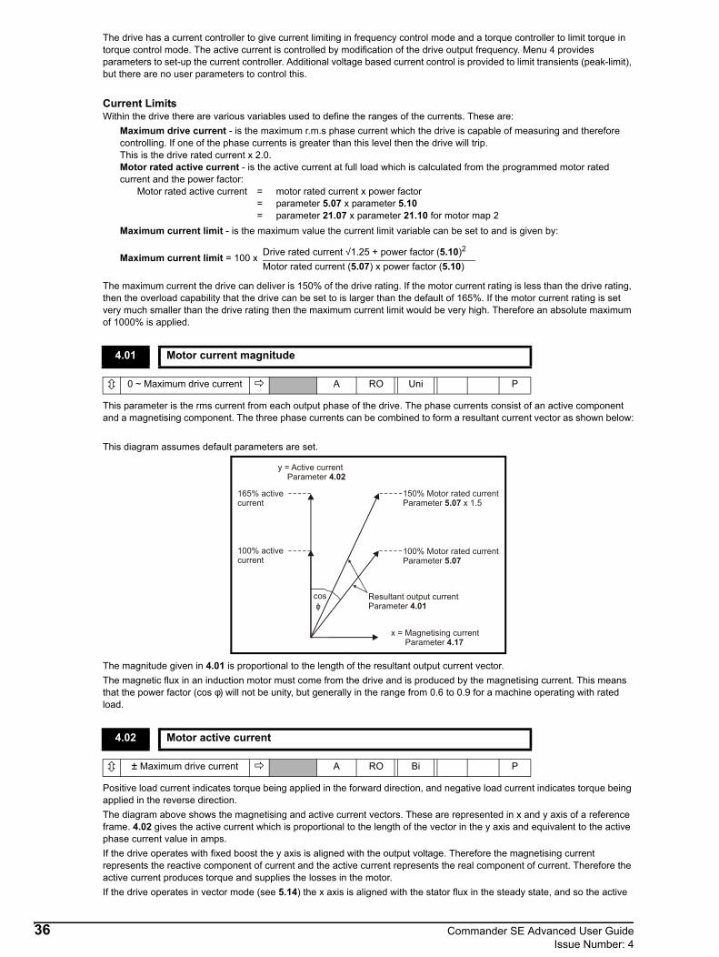
The drive has a current controller to give current limiting in frequency control mode and a torque controller to limit torque in torque control mode. The active current is controlled by modification of the drive output frequency. Menu 4 provides parameters to set-up the current controller. Additional voltage based current control is provided to limit transients (peak-limit), but there are no user parameters to control this.
Current LimitsWithin the drive there are various variables used to define the ranges of the currents. These are:
Maximum drive current - is the maximum r.m.s phase current which the drive is capable of measuring and therefore controlling. If one of the phase currents is greater than this level then the drive will trip. This is the drive rated current x 2.0.Motor rated active current - is the active current at full load which is calculated from the programmed motor rated current and the power factor:
Motor rated active current = motor rated current x power factor= parameter 5.07 x parameter 5.10= parameter 21.07 x parameter 21.10 for motor map 2
Maximum current limit - is the maximum value the current limit variable can be set to and is given by:
The maximum current the drive can deliver is 150% of the drive rating. If the motor current rating is less than the drive rating, then the overload capability that the drive can be set to is larger than the default of 165%. If the motor current rating is set very much smaller than the drive rating then the maximum current limit would be very high. Therefore an absolute maximum of 1000% is applied.
This parameter is the rms current from each output phase of the drive. The phase currents consist of an active component and a magnetising component. The three phase currents can be combined to form a resultant current vector as shown below:
This diagram assumes default parameters are set.
The magnitude given in 4.01 is proportional to the length of the resultant output current vector. The magnetic flux in an induction motor must come from the drive and is produced by the magnetising current. This means that the power factor (cos φ) will not be unity, but generally in the range from 0.6 to 0.9 for a machine operating with rated load.
Positive load current indicates torque being applied in the forward direction, and negative load current indicates torque being applied in the reverse direction.The diagram above shows the magnetising and active current vectors. These are represented in x and y axis of a reference frame. 4.02 gives the active current which is proportional to the length of the vector in the y axis and equivalent to the active phase current value in amps.If the drive operates with fixed boost the y axis is aligned with the output voltage. Therefore the magnetising current represents the reactive component of current and the active current represents the real component of current. Therefore the active current produces torque and supplies the losses in the motor.If the drive operates in vector mode (see 5.14) the x axis is aligned with the stator flux in the steady state, and so the active
Maximum current limit = 100 x Drive rated current √1.25 + power factor (5.10)2
Motor rated current (5.07) x power factor (5.10)
4.01 Motor current magnitude
0 ~ Maximum drive current A RO Uni P
4.02 Motor active current
± Maximum drive current A RO Bi P
165% active current
100% active current
cos ϕ
y = Active current Parameter 4.02
x = Magnetising current Parameter 4.17
150% Motor rated currentParameter x 1.55.07
100% Motor rated currentParameter 5.07
Resultant output currentParameter 4.01
36 Commander SE Advanced User GuideIssue Number: 4

current should be proportional to the torque produced by the machine. The active current will give a good indication of the machine torque over most of the frequency range, however, the accuracy is reduced below 10Hz.In both cases the relationship between the active current and motor torque will change once the maximum drive output voltage or the rated voltage of the motor set by 5.09 is reached, whichever is the lowest. (Generally the maximum drive output voltage will be just below the r.m.s. line supply voltage.) Once one of these limits is reached the voltage is held constant and the motor flux reduces with frequency. This is referred to as field weakening or constant power operation. In this region the relationship between torque and active current is approximately as follows, where K is a constant related to the motor:
Torque = K x active current x frequency at voltage limit / actual frequency Normally the point at which the voltage limit is reached is close to the rated frequency of the motor.
*Units: % of rated active currentThe current demand is limited by the Active current limit. If torque control mode is selected (4.11 = 1) this becomes the active current demand for the drive. The current demand is shown as percentage of rated active current which is defined by the user set up of the drive. Below the frequency where the output voltage is limited, the torque demand and active current are the same. Above the point where the voltage limit is active the torque and current are related by:
Current demand = (4.08) x output frequency (5.01) / rated frequency (5.06) = 4.08 x 5.01 / 5.06
*Units: % of rated active currentThis parameter defines the current limit as a percentage of (5.07 or 21.07) x (5.10 or 21.10) rated active current. The maximum value allowed for the motor rated current is the drive rated current. The maximum current limit parameter is given by:
Therefore, by setting the motor rated current below the drive rated current it is possible to have a current limit higher than 165%. Therefore, an absolute maximum of 1000% is applied.In frequency control mode (4.11 = 0), the drive output frequency is modified if necessary to keep the active current within the current limits as shown below:
The active current limit is compared with the active current and if the current exceeds the limit the error value passes through the PI controller to give a frequency component which is used to modify the ramp output. The direction of the modification is always to reduce the frequency to zero if the active current is motoring, or to increase the frequency towards the maximum if the current is regenerating. Even when the current limit is active the ramp still operates, therefore the proportional and integral gains (4.13 and 4.14) must be high enough to counter the effects of the ramp. For method of setting the gains see 4.13 and 4.14. In torque control mode the current demand is limited by the current limits. For operation of this mode see 4.11.
4.03 Unused parameter
4.04 Current demand
± Over-riding current limit * RO Bi P
4.05~4.06 Unused parameters
4.07 Current limit
0 ~ +Maximum current limit 165 * RW Uni
Maximum current limit = 100 x Drive rated current √1.25 + power factor (5.10)2
Motor rated current (5.07) x power factor (5.10)
Ramp
Current limitactive
P 04.13I 04.14
Activecurrent
Currentlimit
1 0
Post rampreference
+
-
Active
Commander SE Advanced User Guide 37Issue Number: 4

*Units: % of rated active currentMain torque reference parameter. A positive value is required for torque to be applied in the forward direction, and a negative value is required for torque to be applied in the reverse direction.For a negative value, program a digital input to the analog input invert bit. This will give a negative value on the analog input destination parameter.If operating in torque control (4.08 = 1), due to small errors in current measurement at low frequencies, with zero torque reference and light load, the drive may allow the motor to turn. The direction of rotation, while in torque control, is determined by the polarity of the torque reference. Therefore at power up with zero torque reference and with the drive enabled the motor may turn in either direction. The reason for this is because any error in the current feedback may be a positive or negative value. If the error is negative the motor can turn in the reverse direction and if the error is positive the motor can turn in the forward direction.If it is necessary to guarantee the direction of rotation at power up, while in torque control, then a small positive or negative value must be present in 4.08.
If this parameter is 0 normal frequency control is used. If this parameter is set to 1 the current demand is connected to the current PI controller giving closed loop torque/current control as shown below. The current error is passed through proportional and integral terms to give a frequency reference. The frequency reference is limited to the range -maximum frequency to + maximum frequency as defined by 1.06 ±20%.
To change from speed control to torque control or vice versa, the drive must be either disabled, tripped or in stand-by mode.When this parameter is set to 1, slip compensation is automatically disabled to prevent overspeed trips (O.SP).
These parameters control the proportional and integral gains of the current controller. As already mentioned the current controller either provides current limits or closed loop torque control by modifying the drive output frequency. Although the default settings have been chosen to give suitable gains for less demanding applications it may be necessary for the user to adjust the performance of the controller. The following is a guide to setting the gains for different applications.
4.08 Torque reference
Maximum current limit 0 * RW Bi
4.09 ~ 4.10 Unused parameters
4.11 Torque mode selector
0 or 1 0 RW Bit
4.12 Unused parameter
4.13 Current loop proportional gain
0 ~ 250 20 RW Uni
4.14 Current loop integral gain
0 ~ 250 40 RW Uni
P 04.13I 04.14
Activecurrent
Currentdemand
Frequencyreference
+
-
Active
NOTE
38 Commander SE Advanced User GuideIssue Number: 4

Current limit operationThe current limits will normally operate with an integral term only, particularly below the point where field weakening begins. The proportional term is inherent in the loop. The integral term must be increased enough to counter the effect of the ramp which is still active even in current limit. For example, if the drive is operating at constant frequency and is overloaded the current limit system will try to reduce the output frequency to reduce the load. At the same time the ramp will try to increase the frequency back up to the demand level. If the integral gain is increased too far the first signs of instability will occur when operating around the point where field weakening begins. These oscillations can be reduced by increasing the proportional gain.
Torque controlAgain the controller will normally operate with an integral term only, particularly below the point where field weakening begins. The first signs of instability will appear around base speed, and can be reduced by increasing the proportional gain. The controller tends to be less stable in torque control mode than when it is used for current limiting. This is because load helps to stabilise the controller, and under torque control the drive may operate with light load. Under current limit the drive is often under heavy load unless the current limits are set at a low level.
The motor is modelled thermally in a way that is equivalent to the following electrical circuit:
Where: Vc represents the temperature of the motorVin represents the amount of energy losses in the motor
The energy loss in the motor is proportional to the current squared and it is assumed that the motor reaches rated temperature at rated current in a time determined by the thermal time constant of the motor. 4.15 defines the time constant of the circuit above and should be set to the thermal time constant of the motor.
To allow for tolerances in current measurement the trip threshold for Vc is set at (105% of motor rated current)2
i.e. (5.07 x 1.05)2.
The drive will trip if the following is true:
I2 (1 - e-t/τ) = (5.07 x 1.05)2
Therefore time to trip with 150% rated motor current (5.07) = -4.15 ln(1 - 1052 / 1502). If 4.15 = 89s the time to trip = 60s.
If a different value for the time constant is required it can be calculated as follows:• The motor thermal time constant can be used directly.• A specific overload time and current level can be used, i.e. 60s at 150%
4.15 = -time to trip / ln(1 - 1052 / 1502) = 89• If the reset time from an overload is assumed to be the time it takes for the motor to cool to within 1% of the ambient
temperature, this can be taken as 5 times the thermal time constant.
There are two alternative modes of operation for motor thermal protection defined by 4.16:• If 4.16=0, trip when the trip level is reached.• If 4.16=1, reduction of the current limit to keep the rated current below 100% when the trip level is reached. 5% hysteresis
will be included in this case.
See 4.15 also.4.16 = 0: trip when threshold reached4.16 = 1: reduce current limit when threshold reached
4.15 Motor thermal time constant
0 ~ 250 89 s RW Uni
4.16 Motor protection mode select
0 or 1 0 RW Bit
C
R
VcVin
Commander SE Advanced User Guide 39Issue Number: 4

This parameter is proportional to the length of the vector in the x axis of the reference frame and is equivalent to the magnetising current in each output phase in amps.
*Units: % of rated active current limitThis parameter is an indication of the internal active current limit, it's range depends on the settings of 5.07 (or 21.07) and 5.10 (or 20.10) and could be very high if the motor rating is set very much smaller than the drive rating. For this reason an absolute maximum of 1000% is applied.
*Units: % of trip levelThis parameter gives a continuous indication of modelled motor temperature as a percentage of the trip level. When this parameter reaches 100% the drive will give an Ixt trip or apply a restriction on the current limit. The level of the accumulator is given by:
4.19 = (4.012 (1 - e-t/4.15) / (5.07 x 1.05)2) x 100%
*Units: % of motor rated active currentThis parameter indicates the drive loading as a percentage of motor rated active current, where the 100% rated active is 5.07 x 5.10. Therefore:
4.20 = motor active current (4.02) x 100% / motor rated current (5.07) x power factor (5.10)
A positive value in this parameter indicates motoring load and a negative value indicates a regenerating load.
This parameter defines whether percentage load or output current is displayed.0 Ld Value of parameter 4.20 displayed1 A Value of parameter 4.01 displayed
4.17 Motor magnetising current
0 ~ Maximum drive current A RO Bi P
4.18 Over-riding current limit
0 ~ Maximum current limit * RO Uni P
4.19 Overload accumulator
0 ~ 100.0 * RO Uni P
4.20 Drive load indicator
± Over-riding current limit * RO Bi P
4.21 Load indication selector
0 or 1 0 RO Uni Txt
40 Commander SE Advanced User GuideIssue Number: 4

Post
-ram
pre
fere
nce
2.0
1
P g
ain
4.1
3 I
gain
4
.14
Tor
que
mod
e se
lect
or
4
.11
Cur
rent
dem
and
4.0
4
%
Pre-
ram
pre
fere
nce
1.0
3
M
enu
2R
amp
cont
rol
Cur
rent
lim
it a
ctiv
e 1
0.09
Mot
or fr
eque
ncy
5
.01
Mot
or0 1
01
1 0
Cur
rent
lim
it
4.07
Ove
rload
det
ectio
n
4.1
5 M
otor
ther
mal
ti
me
cons
tant
4.1
6 M
otor
p
rote
ctio
n
m
ode
C
urre
nt m
easu
rem
ent
4
.01
Mag
nitu
de
4
.17
Mag
netis
ing
Act
ive
4.0
2
Loa
d 4
.20
Ove
rload
accu
mul
ator
4.1
9
Ala
rm 1
0.17
4.1
8O
ver-r
idin
gcu
rrent
limit
%
5
.01
M
otor
frequ
ency T
orqu
e to
c
urre
ntco
nver
sion
Tor
que
refe
renc
e
4.0
8
R
ated
fre
quen
cy
5.
06
*21.
06
M
Men
u 5
Mot
or m
ap
* In
dica
tes p
aram
eter
from
seco
nd m
otor
map
Men
u 1
ME
NU
4C
urre
nt c
ontr
ol
Commander SE Advanced User Guide 41Issue Number: 4

3.5 Menu 5: Machine controlParameter Range Type Default Setting
5.01 Motor frequency ±[1.06]Hz RO Bi P L35.02 Motor voltage 240-480V RO Bi P B
5.03 Total motor power (Output power from drive) ± P max(kW) RO Bi P B
5.04 Motor rpm ±9999rpm RO Bi P B
5.05 DC Bus voltage
400V units = 0 ~ 830V
200V units = 0 ~ 420V
RO Uni P B
5.06 Motor rated frequency 0 ~ 1000.0 Hz RW Uni EUR> 50.0USA> 60.0 BS, MC
5.07 Motor rated current 0 ~ Drive rating RW Uni FLC BS, MC
5.08 Motor rated full load rpm 0 ~ 9999rpm RW Uni EUR> 1500USA> 1800 BS, MC
5.09 Motor rated voltage
400V units = 0 ~ 480V
200V units = 0 ~ 240V
RW Uni
EUR> 400V units = 400V 200V units = 230VUSA> 400V units = 460V 200V units = 230V
BF, MC
5.10 Motor rated power factor 0 ~ 1.00 RW Uni 0.85 BS, MC5.11 No of motor poles 0 ~ 4 RW Uni Txt (Auto)0 BS, MC5.12 Autotune 0 ~ 2 RW Uni 0 B5.13 Variable V to F select 0 or 1 RW Bit 0 BS, MC5.14 Voltage mode selector 0 ~ 3 RW Uni 3 BS, MC
5.15 Low frequency voltage boost 0 ~ 25.0% of [5.09] RW Uni 3.0 BF, MC
5.16 Not used5.17 Stator resistance 0 ~ 99.99Ω RW Uni 0.0 BS, MC
5.18 PWM switching frequency selector 3,6,12 kHz(0 ~ 2) RW Uni Size 1 to 4: (1)6kHz
Size 5: (0)3kHz B
5.19 High stability space vector modulation select 0 or 1 RW Bit 0 B
5.20~ 5.22 Not used
5.23 Voltage offset 0 ~ 25.5V RW Uni BF, MC5.24 Motor leakage inductance 000.0 ~ 500.0mH RO Uni P A5.25~ 5.33 Not used
5.34 Speed indication selector 0 ~ 2 RW Uni Txt P 0(Fr) B
42 Commander SE Advanced User GuideIssue Number: 4

The range of this parameter is 1.06 (or 21.01) plus whatever is added or subtracted by the current limit algorithm and for the slip compensation.This parameter gives the output frequency of the drive. This is the sum of the post ramp reference and the slip compensation:
2.01+ rated slip frequency x 4.02 / rated active current2.01 is limited to the maximum frequency defined by 1.06, plus a margin of 20% to allow the drive to control current effectively at maximum speed, but the final frequency can exceed this by the slip compensation frequency.
This is the fundamental line voltage at the inverter output.
This is the total output power of the drive. This is calculated from the in phase components of voltage and current such that the total real output power is measured.The range of this parameter is calculated by the above equation.
I Max = 150% of drive rated current
The motor rpm is calculated from the post ramp reference (2.01). The speed of rotation is calculated as follows:rpm = 60 x frequency / No of pole pairs = 60 x 2.01 / (5.11 / 2)
The result will be accurate providing the slip compensation has been set up correctly with the rated full load speed parameter (5.08).However, if 5.11 = 0 (default), the drive calculates the number of poles automatically and so the above equation is not applicable.
Voltage across the internal DC Bus of the drive
The motor rated frequency is used to define the voltage to frequency characteristic applied to the drive (see 5.09 and 5.14).
The motor rated current should be set to the machine nameplate value for rated current.This value is used in the following:
Current limit, parameter 4.07IxT system, parameter 4.15Slip compensation, parameter 5.08Dynamic V to F control, parameter 5.13
5.01 Motor frequency
±parameter 1.06 (or 21.01) Hz RO Bi P
5.02 Motor voltage
Max Volts V RO Bi P
5.03 Total motor power (Output power from drive)
√3 x I Max x 5.091000 kW RO Bi P
5.04 Motor rpm
±9999 rpm RO Bi P
5.05 DC Bus voltage
400V units > 0 ~ 830200V units > 0 ~ 420
V RO Uni P
5.06 Motor rated frequency
0 ~ 1000EUR> 50.0USA> 60.0
Hz RW Uni
5.07 Motor rated current
0 ~ Drive rated current Drive rated current A RW Uni
Commander SE Advanced User Guide 43Issue Number: 4

The rated full load rpm is used with the motor rated frequency and No. of poles to calculate the rated slip of the induction machine in Hz.
Rated slip = motor rated frequency - (No. of pole pairs x motor full load rpm / 60) = 5.06 - ((5.11 / 2) x 5.08 / 60)
The rated slip is used to calculate the frequency adjustment required to compensate for slip from the following equation:Slip compensation = rated slip x active current / rated active current
If slip compensation is required this parameter should be set to the name-plate value, which should give the correct rpm for a hot machine.Sometimes it will be necessary to adjust this when the drive is commissioned because the nameplate value might be inaccurate. Slip compensation will operate correctly for below base speed and field weakening operation. Slip compensation is used to prevent a “droop” in motor shaft speed as load is applied. If the motor full load speed is set below the synchronous speed, the slip compensation will increase the output frequency with a motoring load and decrease the frequency with a regenerative load both operating in the forward direction. The opposite is true for reverse direction.
A value of zero entered into parameter 07 means slip compensation is disabled
If the full load speed of the motor is above 9999rpm, enter a value of 0 in parameter 07. This will disable slip compensation as values greater than 9999 cannot be entered into this parameter.
Slip compensation should be disabled when using Commander SE on a high inertia load, e.g. fan.
This voltage is used in conjunction with the motor rated frequency 5.06 to define the voltage to frequency characteristic applied to the machine. If fixed boost is selected (5.14 = 2) the following characteristic is used.
If vector mode is selected (5.14 = 0 or 1) the voltage characteristic is a function of the stator resistance (5.17), voltage offset (5.23) and power factor (5.10), all are required to be set up accurately for optimum performance. At no load, the output voltage will be equal to the rated voltage at the rated frequency.
5.08 Motor rated full load rpm
0 ~ 9999Eur> 1500USA> 1800
rpm RW Uni
5.09 Motor rated voltage
EUR: 50Hz Defaults400V units > 0 ~ 480200V units> 0 ~ 240
400V units> 400200V units> 230
V RW Uni
USA: 60Hz Defaults 400V units > 0 ~ 480200V units > 0 ~ 240
400V units> 460200V units> 230
V RW Uni
NOTE
NOTE
NOTE
voltage boost
outputvoltage
05.09
05.09 / 2
05.06 / 2 05.06 outputfrequency
Output voltage characteristic
44 Commander SE Advanced User GuideIssue Number: 4
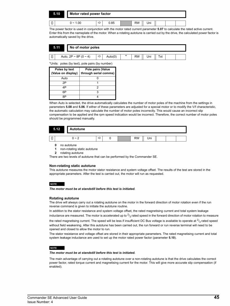
The power factor is used in conjunction with the motor rated current parameter 5.07 to calculate the rated active current. Enter this from the nameplate of the motor. When a rotating autotune is carried out by the drive, the calculated power factor is automatically saved by the drive.
*Units: poles (by text), pole pairs (by number)
When Auto is selected, the drive automatically calculates the number of motor poles of the machine from the settings in parameters 5.08 and 5.06. If either of these parameters are adjusted for a special motor or to modify the V/f characteristic, the automatic calculation may calculate the number of motor poles incorrectly. This would cause an incorrect slip compensation to be applied and the rpm speed indication would be incorrect. Therefore, the correct number of motor poles should be programmed manually.
0 no autotune1 non-rotating static autotune2 rotating autotune
There are two levels of autotune that can be performed by the Commander SE.
Non-rotating static autotuneThis autotune measures the motor stator resistance and system voltage offset. The results of the test are stored in the appropriate parameters. After the test is carried out, the motor will run as requested.
The motor must be at standstill before this test is initiated.
Rotating autotuneThe drive will always carry out a rotating autotune on the motor in the forward direction of motor rotation even if the run reverse command is given to initiate the autotune routine.In addition to the stator resistance and system voltage offset, the rated magnetising current and total system leakage inductance are measured. The motor is accelerated up to 2/3 rated speed in the forward direction of motor rotation to measure
the rated magnetising current. The speed will be less if insufficient DC Bus voltage is available to operate at 2/3 rated speed without field weakening. After this autotune has been carried out, the run forward or run reverse terminal will need to be opened and closed to allow the motor to run.The stator resistance and voltage offset are stored in their appropriate parameters. The rated magnetising current and total system leakage inductance are used to set up the motor rated power factor (parameter 5.10).
The motor must be at standstill before this test is initiated.
The main advantage of carrying out a rotating autotune over a non-rotating autotune is that the drive calculates the correct power factor, rated torque current and magnetising current for the motor. This will give more accurate slip compensation (if enabled).
5.10 Motor rated power factor
0 ~ 1.00 0.85 RW Uni
5.11 No of motor poles
Auto, 2P ~ 8P (0 ~ 4) Auto(0) * RW Uni Txt
Poles by text (Value on display)
Pole pairs (Value through serial comms)
Auto 02P 14P 26P 38P 4
5.12 Autotune
0 ~ 2 0 RW Uni
NOTE
NOTE
Commander SE Advanced User Guide 45Issue Number: 4

Autotune ProcedureBefore a non-rotating static autotune is carried out, the drive’s motor map parameters should be correctly set:
Parameter 5.07 - motor rated currentParameter 5.08 - motor rated full load rpmParameter 5.09 - motor rated voltageParameter 5.10 - motor power factor
Before a rotating autotune is carried out, additional parameters should be correctly set (this is only true if the motor is not a standard 50/60Hz motor).
Parameter 5.06 - motor rated frequencyParameter 1.06 - maximum speed
Although parameter 5.12 is defaulted to ‘no autotune’, on the very first power up, Enable and Run command of the drive after delivery from the factory, the drive will initiate a non-rotating static autotune. After this test, the autotune will be dependent on the value set in parameter 5.12. The results of this test will depend on what is connected to the drive’s motor terminals.
When default parameters are set (see parameter 11.43) the first time the drive is given an Enable and Run command, a non-rotating autotune will be initiated.
No motor connectedWith no motor connected, the drive will trip on ‘rS’ which indicates a stator resistance measurement failure, this will be stored by the drive as zero ohms. The trip can be reset and the drive run as normal. If the drive is powered down and then back up, after an enable and run signal, it will again perform a non-rotating static autotune and trip on ‘rS’.
Motor connected but stator resistance higher than allowable valueThe drive will again trip on ‘rS’ if the stator resistance being measured is greater than the drive’s internal maximum limit. This can happen if a star connected motor is connected to a 200V Commander SE or a motor of a lower kW rating is connected to a larger kW Commander SE. In this case, the drive will store the maximum allowable stator resistance for that size of drive. If the drive is powered down and then back up, after an enable and run signal, it will not perform another autotune.
Motor connected but current levels required for successful autotune not reachedThe drive will trip on ‘rS’ if the current levels required to measure the stator resistance are not reached in the allowable test time, this will be stored by the drive as zero ohms. This can occur because a combination of stator resistance and motor voltage prevents the required current levels being reached. If the drive is powered down and then back up, after an enable and run signal, it will again perform a non-rotating static autotune.The current levels required for a successful autotune are both half and full motor rated current (parameter 5.07). Two measurements are taken to ensure accurate results.
Important Notes:
It is important to ensure that the motor wiring configuration is correct (i.e. Star / Delta) before performing an autotune.
If any changes are made to the drive’s motor map parameters, system wiring, motor wiring configuration or motor type, the drive must be re-autotuned to the motor. Not performing another autotune will result in poor motor performance, OI.AC or IT.AC trips.
0 Fixed linear voltage to frequency ratio (constant torque - standard load).1 Voltage to frequency ratio dependant on load current (dynamic / variable torque - fan / pump load).
5.13 Variable V to F select
0 or 1 0 RW Bit
NOTE
NOTE
NOTE
46 Commander SE Advanced User GuideIssue Number: 4
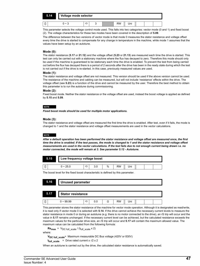
This parameter selects the voltage control mode used. This falls into two categories: vector mode (0 and 1) and fixed boost (2). The voltage characteristics for these two modes have been covered in the description of 5.09.The difference between the two versions of vector mode is that mode 0 measures the stator resistance and voltage offset every time the drive is started to compensate for any change in temperature in the machine, while mode 1 assumes that the values have been setup by an autotune.
Mode (0):The stator resistance (5.17 or 21.12) and the voltage offset (5.23 or 21.13) are measured each time the drive is started. This test can only be carried out with a stationary machine where the flux has decayed to zero. Therefore this mode should only be used if the machine is guaranteed to be stationary each time the drive is enabled. To prevent the test from being carried out before the flux has decayed there is a period of 2 seconds after the drive has been in the ready state during which the test is not carried out if the drive is re-started. In this case, previously measured values are used.Mode (1):The stator resistance and voltage offset are not measured. This version should be used if the above version cannot be used. The resistance of the machine and cabling can be measured, but will not include ‘resistance’ effects within the drive. The voltage offset (see 5.23) is a function of the drive and cannot be measured by the user. Therefore the best method to obtain this parameter is to run the autotune during commissioning.Mode (2):Fixed boost mode. Neither the stator resistance or the voltage offset are used, instead the boost voltage is applied as defined by 5.15 and 5.09.
Fixed boost mode should be used for multiple motor applications.
Mode (3):The stator resistance and voltage offset are measured the first time the drive is enabled. After test, even if it fails, the mode is changed to 1 and the stator resistance and voltage offset measurements are used in the vector calculations.
After a default operation has been performed the stator resistance and voltage offset are measured once, the first time the drive is enabled. If the test passes, the mode is changed to 1 and the stator resistance and voltage offset measurements are used in the vector calculations. If the test fails due to not enough current being drawn i.e. no motor connected, the mode will remain at 3. See parameter 5.12 - Autotune.
The boost level for the fixed boost characteristic is defined by this parameter.
This parameter stores the stator resistance of the machine for vector mode operation. Although it is designated as read/write, it is read only if vector mode 0 is selected with 5.14. If the drive cannot achieve the necessary current levels to measure the stator resistance in mode 0 or during an autotune (e.g. there is no motor connected to the drive), an rS trip will occur and the value in 5.17 remains unchanged. If the necessary current level can be achieved, but the calculated resistance exceeds the maximum values for the particular drive size, an rS trip will occur and 5.17 will contain the maximum allowed value. The maximum value can be calculated from the following formula:
Rsmax = VDC full_scale / (Ifull_scale x 2)where:
VDC full_scale= Maximum measurable DC Bus voltage (420V or 830V)Ifull_scale = Drive rated current x √2 x 2
When an autotune is carried out by the drive, the calculated stator resistance is automatically saved.
5.14 Voltage mode selector
0 ~ 3 3 RW Uni
5.15 Low frequency voltage boost
0 ~ 25.0 3.0 % RW Uni
5.16 Unused parameter
5.17 Stator resistance
0 ~ 99.99 0.0 Ω RW Uni
NOTE
NOTE
Commander SE Advanced User Guide 47Issue Number: 4

This parameter is used to select the required switching frequency.
12kHz is not available on SE size 5.
Intelligent Thermal Management The Commander SE contains a heatsink thermistor that monitors the temperature of the drive’s heatsink. If the switching frequency is set above 3kHz and the heatsink temperature increases above set levels, the drive will reduce the switching frequency in order to prevent the drive from tripping on heatsink over-temperature (Oht2). If the switching frequency is set to 3kHz and the heatsink temperature increases above the maximum allowable level, the drive will trip on Oht2.The drive also contains a software thermal model that calculates the IGBT power semiconductor junction temperatures. This temperature will be greater than the thermistor temperature especially under thermal shock conditions because of drive thermal impedances and the heatsink thermal mass. If the switching frequency is set above 3kHz and the thermal model calculates an IGBT junction temperature above a set level, the drive will reduce the switching frequency in order to prevent the drive from tripping on thermal model over-temperature, Oht1. If the switching frequency is set to 3kHz and the calculated IGBT junction temperature increases above the maximum allowable level, the drive will trip on Oht1.If the drive’s thermal model reduces the switching frequency in order to prevent the drive from tripping, the drive’s right hand display will alternately flash between the units it is currently displaying and ‘hot’.
Normally the drive will use space vector modulation to produce the IGBT control signals. High stability space vector modulation offers three advantages in an open loop drive, but the acoustic noise produced by the machine may increase slightly.• It is possible for instability to occur around motor rated frequency/2 on light load. To prevent this, high stability space
vector modulation should be enabled by setting this parameter.• As the output voltage approaches the maximum available from the drive, pulse deletion occurs. This can cause unstable
operation with a lightly or fully loaded machine. High stability space vector modulation will reduce this effect.• High stability space vector modulation gives a small reduction in drive heat loss.
High stability space vector modulation is not available on the Commander SE Size 1.
5.18 PWM switching frequency selector
3, 6, 12 (0 ~ 2)Size 1to4: (1) 6
Size 5: (0) 3kHz RW Uni
Drive Condition Action
Heatsink >95°C (Sizes 1 ~ 3 & 5)Heatsink >100°C (Size 4) Trip drive
Heatsink >92°C Reduce switching frequency to 3kHz
Heatsink >88°C Reduce switching frequency to 6kHz
Heatsink <85°C and IGBT temperature at new switching frequency <135°C Allow an increase in switching frequency
IGBT temperature >135°C Reduce switching frequencyIf it is already 3kHz, trip drive
5.19 High stability space vector modulation select
0 or 1 0 RW Bit
5.20 ~ 5.22 Unused parameters
NOTE
NOTE
48 Commander SE Advanced User GuideIssue Number: 4
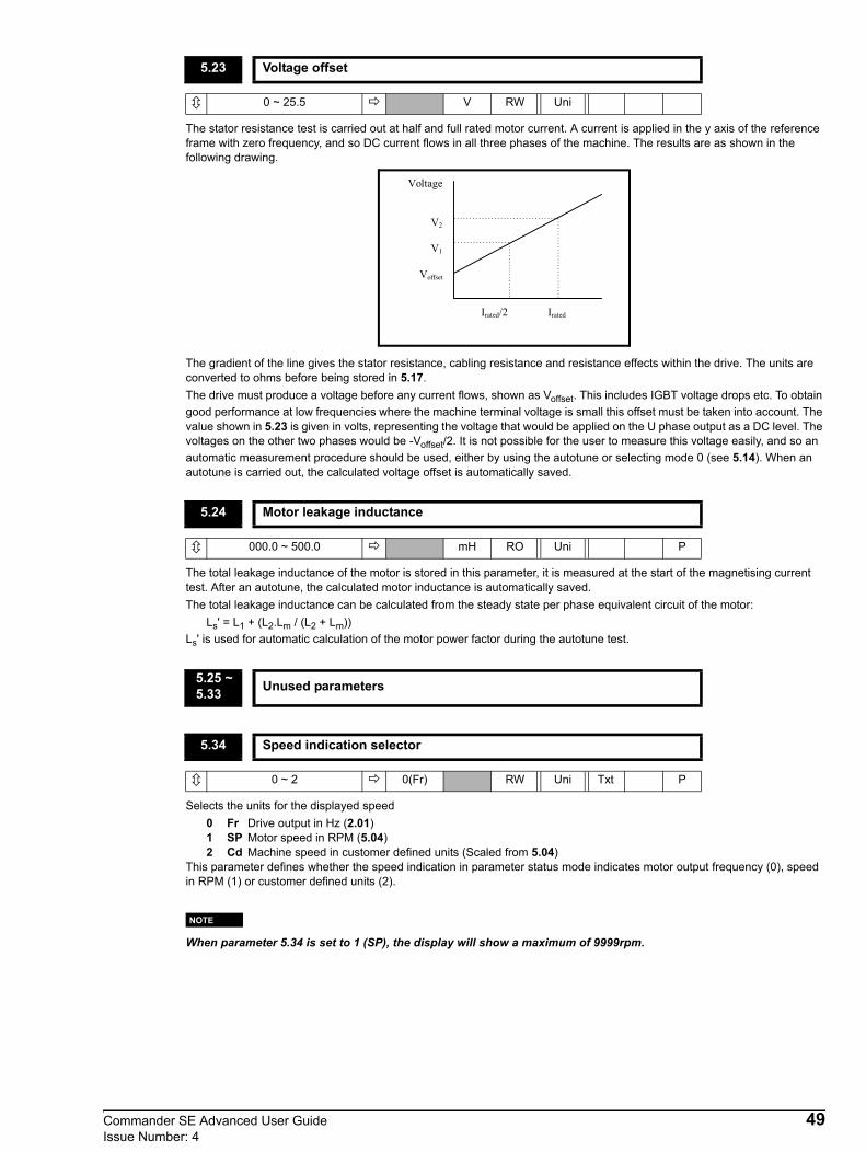
The stator resistance test is carried out at half and full rated motor current. A current is applied in the y axis of the reference frame with zero frequency, and so DC current flows in all three phases of the machine. The results are as shown in the following drawing.
The gradient of the line gives the stator resistance, cabling resistance and resistance effects within the drive. The units are converted to ohms before being stored in 5.17. The drive must produce a voltage before any current flows, shown as Voffset. This includes IGBT voltage drops etc. To obtain good performance at low frequencies where the machine terminal voltage is small this offset must be taken into account. The value shown in 5.23 is given in volts, representing the voltage that would be applied on the U phase output as a DC level. The voltages on the other two phases would be -Voffset/2. It is not possible for the user to measure this voltage easily, and so an automatic measurement procedure should be used, either by using the autotune or selecting mode 0 (see 5.14). When an autotune is carried out, the calculated voltage offset is automatically saved.
The total leakage inductance of the motor is stored in this parameter, it is measured at the start of the magnetising current test. After an autotune, the calculated motor inductance is automatically saved.The total leakage inductance can be calculated from the steady state per phase equivalent circuit of the motor:
Ls' = L1 + (L2.Lm / (L2 + Lm))Ls' is used for automatic calculation of the motor power factor during the autotune test.
Selects the units for the displayed speed0 Fr Drive output in Hz (2.01)1 SP Motor speed in RPM (5.04)2 Cd Machine speed in customer defined units (Scaled from 5.04)
This parameter defines whether the speed indication in parameter status mode indicates motor output frequency (0), speed in RPM (1) or customer defined units (2).
When parameter 5.34 is set to 1 (SP), the display will show a maximum of 9999rpm.
5.23 Voltage offset
0 ~ 25.5 V RW Uni
5.24 Motor leakage inductance
000.0 ~ 500.0 mH RO Uni P
5.25 ~ 5.33 Unused parameters
5.34 Speed indication selector
0 ~ 2 0(Fr) RW Uni Txt P
Voltage
V2
V1
Voffset
Irated/2 Irated
NOTE
Commander SE Advanced User Guide 49Issue Number: 4
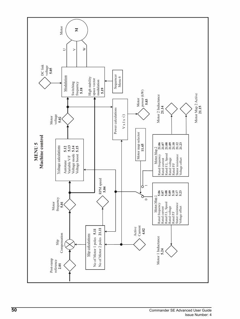
No
of M
otor
1 p
oles
5.
11N
o of
Mot
or 2
pol
es 2
1.11
Mot
or 1
Indu
ctan
ce
5.2
4M
otor
2 In
duct
ance
2
1.14
MEN
U 5
Mac
hine
con
trol
Aut
otun
e
Varia
ble
V/F
Volta
ge m
ode
Vo
ltage
boo
st 5.
12 5.13
5.14
5.15
Mot
or M
ap 2
Act
ive
2
1.15
Mot
or M
ap 1
Rat
ed fr
eque
ncy
Rat
ed c
urre
ntR
ated
F.L
. Spe
edR
ated
vol
tage
Rat
ed P
.FSt
ator
resi
stan
ceVo
ltage
offs
et
5.06
5.07
5.08
5.09
5.10
5.17
5.23
Mot
or M
ap 2
Rat
ed fr
eque
ncy
Rat
ed c
urre
ntR
ated
F.L
. Spe
edR
ated
vol
tage
Rat
ed P
.FSt
ator
resi
stan
ceVo
ltage
offs
et
21.0
621
.07
21.0
821
.09
21.1
021
.12
21.2
3
50 Commander SE Advanced User GuideIssue Number: 4

3.6 Menu 6: Drive sequencer
Parameter Range Type Default Setting Update Rate
6.01 Stop mode selector 0~4 RW Uni 1 L16.02 Not used6.03 AC supply loss mode selector 0~2 RW Uni 0 L26.04 Start/stop logic select 0 ~ 4 RW Uni R 0 B, I6.05 Not used
6.06 Injection braking level 0 ~ Active current limit RW Uni 100 B
6.07 Injection braking time 0.0 ~ 25.0 secs RW Uni 1.0 L16.08 Not used6.09 Synchronize to a spinning motor 0 ~ 3 RW Uni 0 B6.10~ 6.11 Not used
6.12 Keypad stop key enable 0 or 1 RW Bit (EUR) 0(USA) 1 B
6.13 Keypad fwd/rev key enable 0 or 1 RW Bit 0 L16.14 Not used6.15 Drive enable 0 or 1 RW Bit 1 L16.16 Electricity cost/kWh 0.0 ~ 600.0 RW Uni 0 B6.17 Power consumption meter reset 0 or 1 RW Bit 0 B6.18~ 6.21 Not used
6.22 Run time logYears/Days
0 ~ 9.364 Years.Days RO Uni S P B
6.23 Run time logHours/Minutes
0 ~ 23.59 Hours.Minutes RO Uni S P B
6.24 Power meter MWh 0.0 ~ 999.9 Mwh RO Uni S P B6.25 Power meter kWh 0.0 ~ 99.99 kWh RO Uni S P B
6.26 Running cost 0 ~ 32000 Currency/Hour RO Uni P B
6.27~ 6.28 Not used
6.29 Hardware enable 0 or 1 RW Bit 0 L16.30 Digital input control bit 0 (Run/Fwd) 0 or 1 RW Bit 0 L16.31 Digital input control bit 1 (Jog) 0 or 1 RW Bit 0 L16.32 Digital input control bit 2 (Run/Rev) 0 or 1 RW Bit 0 L16.33 Digital input control bit 3 (Fwd/Rev) 0 or 1 RW Bit 0 L16.34 Digital input control bit 4 (Run) 0 or 1 RW Bit 0 L16.35~ 6.38 Not used
6.39 Digital input control bit 5 (Not Stop) 0 or 1 RW Bit 0 L16.40 Enable latching run inputs 0 or 1 RW Bit 0 L16.41 Control word mask RW Uni 0 L16.42 Control word RW Uni 0 L16.43 Control word enable 0 or 1 RW Bit 0 L1
Commander SE Advanced User Guide 51Issue Number: 4
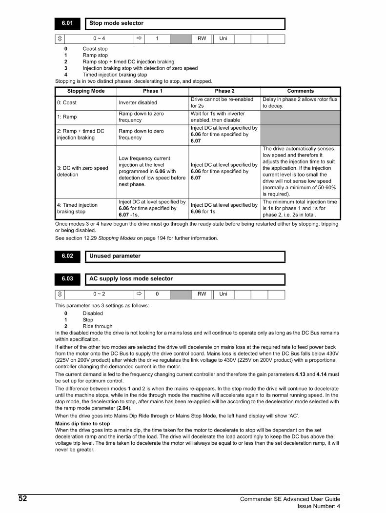
0 Coast stop1 Ramp stop2 Ramp stop + timed DC injection braking3 Injection braking stop with detection of zero speed4 Timed injection braking stop
Stopping is in two distinct phases: decelerating to stop, and stopped.
Once modes 3 or 4 have begun the drive must go through the ready state before being restarted either by stopping, tripping or being disabled.See section 12.29 Stopping Modes on page 194 for further information.
This parameter has 3 settings as follows:0 Disabled1 Stop2 Ride through
In the disabled mode the drive is not looking for a mains loss and will continue to operate only as long as the DC Bus remains within specification.If either of the other two modes are selected the drive will decelerate on mains loss at the required rate to feed power back from the motor onto the DC Bus to supply the drive control board. Mains loss is detected when the DC Bus falls below 430V (225V on 200V product) after which the drive regulates the link voltage to 430V (225V on 200V product) with a proportional controller changing the demanded current in the motor.The current demand is fed to the frequency changing current controller and therefore the gain parameters 4.13 and 4.14 must be set up for optimum control.The difference between modes 1 and 2 is when the mains re-appears. In the stop mode the drive will continue to decelerate until the machine stops, while in the ride through mode the machine will accelerate again to its normal running speed. In the stop mode, the deceleration to stop, after mains has been re-applied will be according to the deceleration mode selected with the ramp mode parameter (2.04).When the drive goes into Mains Dip Ride through or Mains Stop Mode, the left hand display will show ‘AC’.Mains dip time to stopWhen the drive goes into a mains dip, the time taken for the motor to decelerate to stop will be dependant on the set deceleration ramp and the inertia of the load. The drive will decelerate the load accordingly to keep the DC bus above the voltage trip level. The time taken to decelerate the motor will always be equal to or less than the set deceleration ramp, it will never be greater.
6.01 Stop mode selector
0 ~ 4 1 RW Uni
Stopping Mode Phase 1 Phase 2 Comments
0: Coast Inverter disabled Drive cannot be re-enabled for 2s
Delay in phase 2 allows rotor flux to decay.
1: Ramp Ramp down to zero frequency
Wait for 1s with inverter enabled, then disable
2: Ramp + timed DC injection braking
Ramp down to zero frequency
Inject DC at level specified by 6.06 for time specified by 6.07
3: DC with zero speed detection
Low frequency current injection at the level programmed in 6.06 with detection of low speed before next phase.
Inject DC at level specified by 6.06 for time specified by 6.07
The drive automatically senses low speed and therefore it adjusts the injection time to suit the application. If the injection current level is too small the drive will not sense low speed (normally a minimum of 50-60% is required).
4: Timed injection braking stop
Inject DC at level specified by 6.06 for time specified by 6.07 -1s.
Inject DC at level specified by 6.06 for 1s
The minimum total injection time is 1s for phase 1 and 1s for phase 2, i.e. 2s in total.
6.02 Unused parameter
6.03 AC supply loss mode selector
0 ~ 2 0 RW Uni
52 Commander SE Advanced User GuideIssue Number: 4

This parameter changes the functions of terminals 9, 10 and 11 which are normally associated with the enabling, starting and stopping the drive. Setting 6.04 from modes 0 to 3 automatically changes the functions of terminals 9,10 and 11 as in the following table. This automatically writes to 6.40 to enable and disable the input latches as appropriate. The new value only takes effect when the drive is reset when in disabled or tripped state.When 6.04 is set to mode 4, the user is free to assign the terminals as appropriate to their application. Also 6.40 can be set as required.
6.04 must be set to a 4 and saved before the destination parameters of terminals 9,10 and 11 can be reassigned.
This parameter defines the current level used for injection braking.(For definition of Active current limit see Menu 4: Current control).
Defines the time of injection braking for injection braking stop.
This parameter controls which direction of motor speed the drive should detect. When the motor frequency has been detected the output frequency is started from that value and ramped towards the reference.
0 Catch a spinning motor disabled1 Detect all frequencies2 Only detect positive frequencies3 Only detect negative frequencies
For the spinning motor software to function, the drive must perform a non-rotating autotune to measure a stator resistance (see parameters 5.12, 5.14 and 5.17). The drive uses this stator resistance measurement to ‘catch a spinning motor’. On the first enable and run command of the drive from the factory, the drive will perform this autotune.
If the drive is to be set up in fixed boost mode (parameter 5.14 set to 2) an autotune must be performed before the drive is set into fixed boost, so that a stator resistance is measured.If the drive does not perform an autotune to measure a stator resistance, the ‘catch a spinning motor’ software will not perform correctly and 0V or OI.AC trips will be seen. The delay time for the drive to detect the frequency of a spinning motor and act upon it is 500mS.
6.04 Start / stop logic select
0 ~ 4 0 RW Uni R
NOTE
6.04 Terminal 9 Terminal 10 Terminal 11 6.400 (default) Enable Run Forward Run Reverse 0 (non latching)
1 /Stop Run Forward Run Reverse 1 (latching)2 Enable Run Reverse 0 (non latching)3 /Stop Run Reverse 1 (latching)4 User programmable User programmable User programmable User programmable
6.05 Unused parameter
6.06 Injection braking level
0.0 ~ Active current limit 100.0 % RW Uni
6.07 Injection braking time
0.0 ~ 25.0 1.0 s RW Uni
6.08 Unused parameter
6.09 Synchronize to a spinning motor
0 ~ 3 0 RW Uni
6.10 ~ 6.11 Unused parameters
NOTE
Commander SE Advanced User Guide 53Issue Number: 4

This parameter permanently enables the Stop button on the drive such that the drive will always stop when the stop button is pressed.
This parameter enables the Fwd/Rev button on the drive.
Setting this parameter to 0 will disable the drive. It must be at 1 for the drive to run.
*Units: Currency/kWhWhen this parameter is set up correctly for the local currency, 6.26 will give an instantaneous read out of running cost.
Used to reset parameters 6.24 and 6.25 back to zero.
Together with the next parameter the drive records the amount of time the drive has been running since it left the manufacturing plant.
Together with the previous parameter the drive records the amount of time the drive has been running since it left the manufacturing plant.
Drive power consumption meter. This can be reset to zero by setting parameter 6.17.
6.12 Keypad stop key enable
0 or 1Europe> 0USA> 1
RW Bit
6.13 Keypad fwd / rev key enable
0 or 1 0 RW Bit
6.14 Unused parameter
6.15 Drive enable
0 or 1 1 RW Bit
6.16 Electricity cost / kWh
0.0 ~ 600.0 1 * RW Uni
6.17 Power consumption meter reset
0 or 1 0 RW Bit
6.18 ~ 6.21 Unused parameters
6.22 Run time log. years / days
0 ~ 9.364 years/days RO Uni S P
6.23 Run time log. hours / minutes
0 ~ 23.59 hours/mins RO Uni S P
6.24 Power meter MWh
0 ~ 999.9 MWh RO Uni S P
54 Commander SE Advanced User GuideIssue Number: 4

Drive power consumption meter. This can be reset to zero by setting parameter 6.17.Parameter 6.24 and 6.25 give an accumulative value of power used.
Gives a read out of the cost/hour of running the drive. This requires 6.16 to be set up correctly.Parameter 6.26 gives an instantaneous value of running costs.
Provides a means of enabling / disabling the drive from a programmable input. In order that the drive does not always require a separate enable terminal this parameter is automatically set to a 1 if a terminal is not programmed as an enable terminal. When a terminal is set to control this parameter, the terminal always has over-riding control. When a terminal is programmed as an enable terminal, there is a 2 second delay after the drive is disabled before it will re-enable again. This 2 second delay is set in the drives software and cannot be changed.
The drive sequencer uses these bits as inputs rather than looking at terminals directly. This allows the customer to define the use of each drive terminal according to each applications needs.Although these parameters are R/W, they are volatile and are not stored on power down. Every time the drive powers up they will be reset to 0.
6.30 Run Forward 6.31 Jog 6.32 Run Reverse 6.33 Forward/Reverse 6.34 Run 6.39 Not Stop
The drive uses these sequencer bits to control the operation of the drive providing the keypad reference has not been selected. If the keypad reference has been selected, all the sequencing bits are disregarded such that only the keypad keys are used to control the drive, in this mode the Run and Stop keys are always operational, and the Fwd/Rev key is operational if selected.The drive checks the state of the ‘Run Forward’ and ‘Run Reverse’ bits first. If either are set to 1 (but not both) then the drive will run in the commanded direction. If both are found to be 0 then the sequencer looks at the ‘Run’ bit and if it is set then the drive is run in the direction commanded by the ‘Forward/Reverse’ bit (0 = forward, 1 = reverse).If the ‘Jog’ bit is set the sequencer switches 1.13 to 1 to select the Jog reference. The sequencer must also see one of the run commands for the drive to run at the Jog speed.Two of the drives terminals are programmed to control the ‘Run Forward’ and ‘Run Reverse’ bits in the drives default state. For customers who prefer to command the drive with ‘Run’ and ‘Forward/Reverse’ terminals see 6.04.
6.25 Power meter kWh
0.00 ~ 99.99 kWh RO Uni S P
6.26 Running cost
0 ~ 32000 currency/hour RO Uni P
6.27 ~ 6.28 Unused parameters
6.29 Hardware enable
0 or 1 1 RW Bit
6.30 Digital input control bit 0 (Run / Fwd)
6.31 Digital input control bit 1 (Jog)
6.32 Digital input control bit 2 (Run / Rev)
6.33 Digital input control bit 3 (Fwd / Rev)
6.34 Digital input control bit 4 (Run)
6.39 Digital input control bit 5 (Not Stop)
0 or 1 0 RW Bit
Commander SE Advanced User Guide 55Issue Number: 4
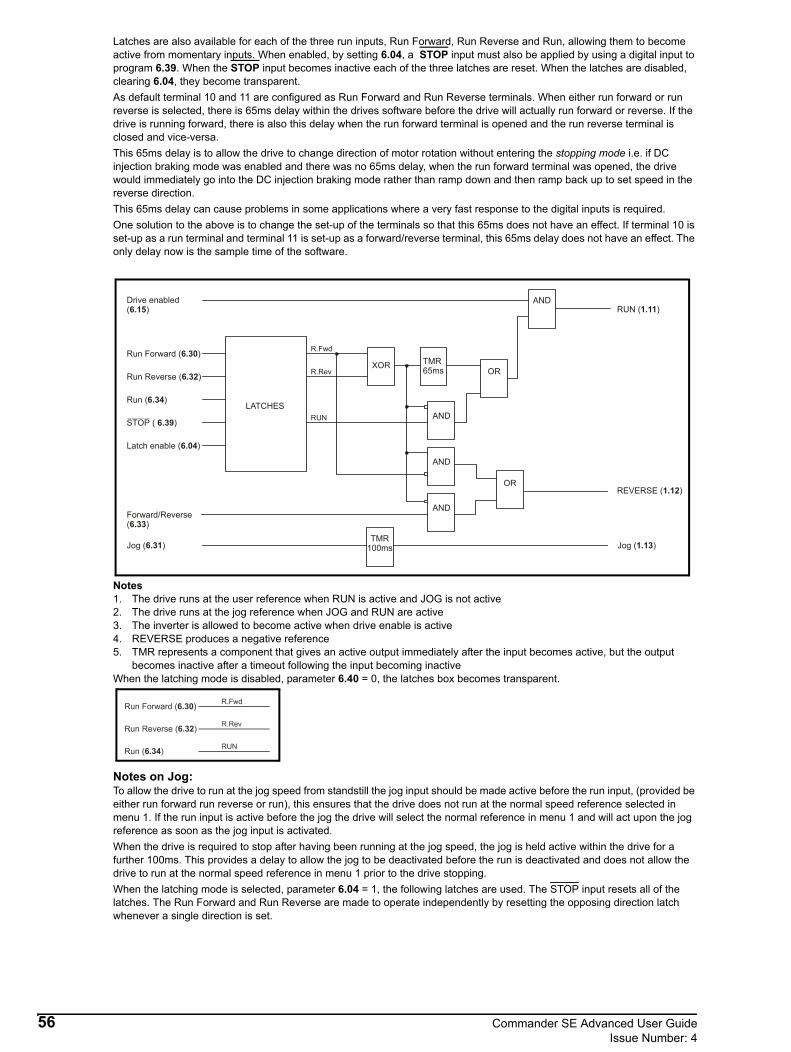
Latches are also available for each of the three run inputs, Run Forward, Run Reverse and Run, allowing them to become active from momentary inputs. When enabled, by setting 6.04, a STOP input must also be applied by using a digital input to program 6.39. When the STOP input becomes inactive each of the three latches are reset. When the latches are disabled, clearing 6.04, they become transparent.As default terminal 10 and 11 are configured as Run Forward and Run Reverse terminals. When either run forward or run reverse is selected, there is 65ms delay within the drives software before the drive will actually run forward or reverse. If the drive is running forward, there is also this delay when the run forward terminal is opened and the run reverse terminal is closed and vice-versa.This 65ms delay is to allow the drive to change direction of motor rotation without entering the stopping mode i.e. if DC injection braking mode was enabled and there was no 65ms delay, when the run forward terminal was opened, the drive would immediately go into the DC injection braking mode rather than ramp down and then ramp back up to set speed in the reverse direction. This 65ms delay can cause problems in some applications where a very fast response to the digital inputs is required.One solution to the above is to change the set-up of the terminals so that this 65ms does not have an effect. If terminal 10 is set-up as a run terminal and terminal 11 is set-up as a forward/reverse terminal, this 65ms delay does not have an effect. The only delay now is the sample time of the software.
Notes1. The drive runs at the user reference when RUN is active and JOG is not active2. The drive runs at the jog reference when JOG and RUN are active3. The inverter is allowed to become active when drive enable is active4. REVERSE produces a negative reference5. TMR represents a component that gives an active output immediately after the input becomes active, but the output
becomes inactive after a timeout following the input becoming inactiveWhen the latching mode is disabled, parameter 6.40 = 0, the latches box becomes transparent.
Notes on Jog:To allow the drive to run at the jog speed from standstill the jog input should be made active before the run input, (provided be either run forward run reverse or run), this ensures that the drive does not run at the normal speed reference selected in menu 1. If the run input is active before the jog the drive will select the normal reference in menu 1 and will act upon the jog reference as soon as the jog input is activated.When the drive is required to stop after having been running at the jog speed, the jog is held active within the drive for a further 100ms. This provides a delay to allow the jog to be deactivated before the run is deactivated and does not allow the drive to run at the normal speed reference in menu 1 prior to the drive stopping.When the latching mode is selected, parameter 6.04 = 1, the following latches are used. The STOP input resets all of the latches. The Run Forward and Run Reverse are made to operate independently by resetting the opposing direction latch whenever a single direction is set.
Drive enabled( )6.15
Run Forward ( )6.30
Run Reverse ( )6.32
Run ( )6.34
STOP ( )6.39
Latch enable ( )6.04
LATCHES
Forward/Reverse( )6.33
Jog ( )6.31
XOR TMR65ms
Jog ( )1.13
REVERSE ( )1.12
RUN ( )1.11
AND
AND
AND
AND
OR
OR
TMR100ms
R.Fwd
R.Rev
RUN
56 Commander SE Advanced User GuideIssue Number: 4

See previous page for details.
This bit can be used to enable latches on the run forward, run reverse and run inputs to allow the drive to be controlled from momentary inputs. See also parameters 6.30 ~ 6.34 and 6.04.A user can use parameters 6.41 Control word mask, 6.42 Control Word and 6.43 Control word enable to start, stop, run forward, run reverse etc. the drive via serial communications.
This parameter in conjunction with parameters 6.42 and 6.43 provides the means of controlling the drives Start/Stop functions via serial communications.The value set in parameter 6.41 is used to define and limit which functions can be controlled by the user i.e. Enable, Run Forward, Run Reverse etc. This value only needs to be set once to the appropriate value. This value is the binary code addition of the functionality required.
This parameter is not saved when the drive is powered off
6.35 ~ 6.38 Unused parameters
6.39 Digital input control bit 5 (Not Stop)
0 or 1 0 RW Bit
6.40 Enable latching run inputs
0 or 1 0 RW Bit
6.41 Control word mask
0 RW Uni
Binary code Function1 Drive Enable2 Run Forward4 Jog8 Run Reverse
16 Forward / Reverse32 Run64 Not Stop
Run Forward ( )6.30
Run Reverse ( )6.32
Run ( )6.34
STOP ( )6.39
Forward/Reverse( )6.33
R.Fwd
R.Rev
RUN
LATCH
LATCH
LATCH
OR
OR
REV
S
S
S
R
R
R
NOTE
Commander SE Advanced User Guide 57Issue Number: 4
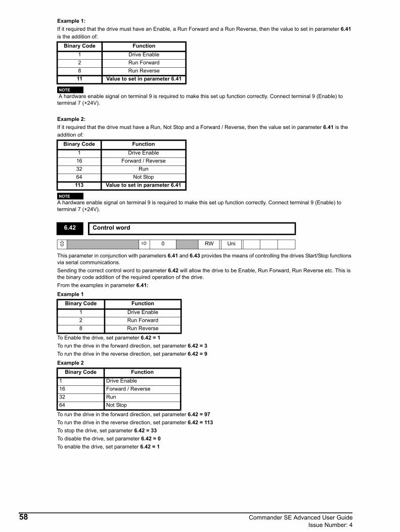
Example 1:If it required that the drive must have an Enable, a Run Forward and a Run Reverse, then the value to set in parameter 6.41 is the addition of:
A hardware enable signal on terminal 9 is required to make this set up function correctly. Connect terminal 9 (Enable) to terminal 7 (+24V).
Example 2:If it required that the drive must have a Run, Not Stop and a Forward / Reverse, then the value set in parameter 6.41 is the addition of:
A hardware enable signal on terminal 9 is required to make this set up function correctly. Connect terminal 9 (Enable) to terminal 7 (+24V).
This parameter in conjunction with parameters 6.41 and 6.43 provides the means of controlling the drives Start/Stop functions via serial communications.Sending the correct control word to parameter 6.42 will allow the drive to be Enable, Run Forward, Run Reverse etc. This is the binary code addition of the required operation of the drive.From the examples in parameter 6.41:Example 1
To Enable the drive, set parameter 6.42 = 1To run the drive in the forward direction, set parameter 6.42 = 3To run the drive in the reverse direction, set parameter 6.42 = 9Example 2
To run the drive in the forward direction, set parameter 6.42 = 97To run the drive in the reverse direction, set parameter 6.42 = 113To stop the drive, set parameter 6.42 = 33To disable the drive, set parameter 6.42 = 0To enable the drive, set parameter 6.42 = 1
Binary Code Function1 Drive Enable2 Run Forward8 Run Reverse11 Value to set in parameter 6.41
Binary Code Function1 Drive Enable
16 Forward / Reverse32 Run64 Not Stop113 Value to set in parameter 6.41
6.42 Control word
0 RW Uni
Binary Code Function1 Drive Enable2 Run Forward8 Run Reverse
Binary Code Function1 Drive Enable16 Forward / Reverse32 Run64 Not Stop
NOTE
NOTE
58 Commander SE Advanced User GuideIssue Number: 4
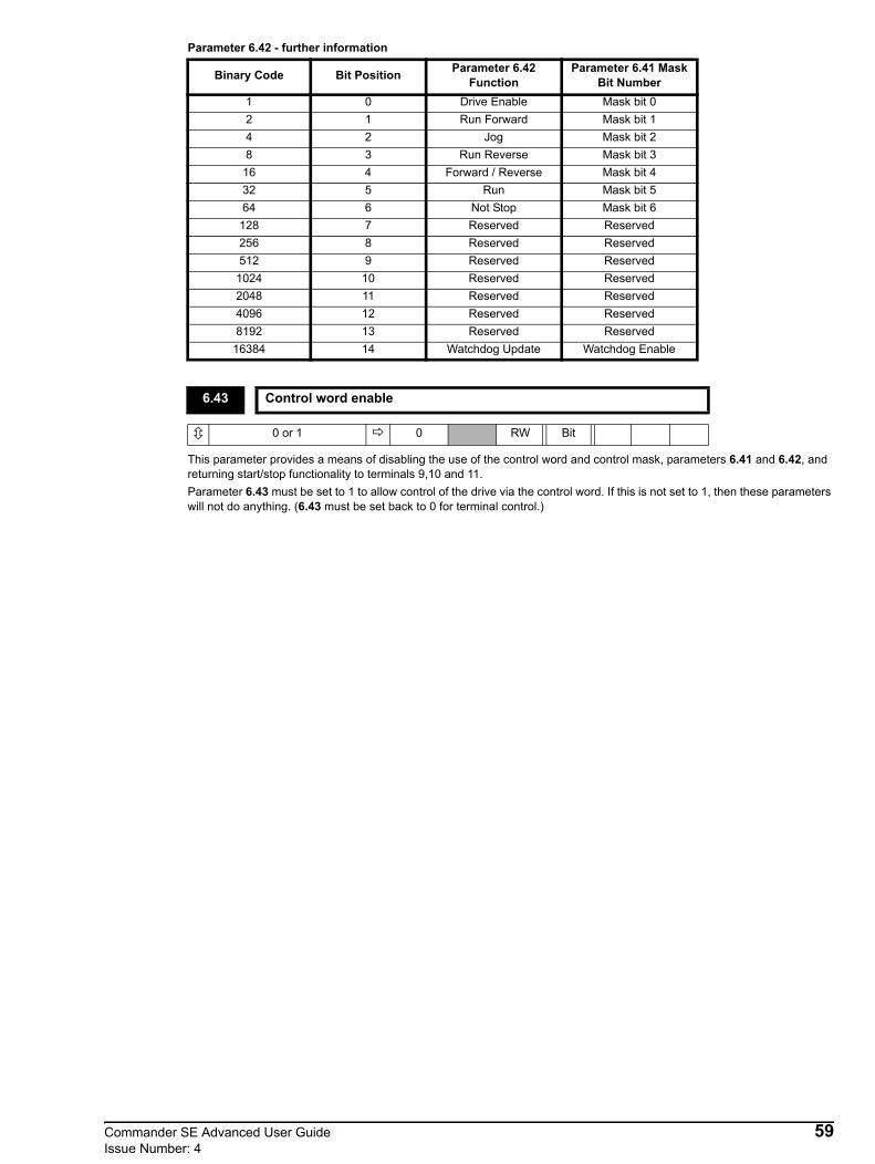
Parameter 6.42 - further information
This parameter provides a means of disabling the use of the control word and control mask, parameters 6.41 and 6.42, and returning start/stop functionality to terminals 9,10 and 11.Parameter 6.43 must be set to 1 to allow control of the drive via the control word. If this is not set to 1, then these parameters will not do anything. (6.43 must be set back to 0 for terminal control.)
Binary Code Bit Position Parameter 6.42 Function
Parameter 6.41 Mask Bit Number
1 0 Drive Enable Mask bit 02 1 Run Forward Mask bit 14 2 Jog Mask bit 28 3 Run Reverse Mask bit 3
16 4 Forward / Reverse Mask bit 432 5 Run Mask bit 564 6 Not Stop Mask bit 6
128 7 Reserved Reserved256 8 Reserved Reserved512 9 Reserved Reserved
1024 10 Reserved Reserved2048 11 Reserved Reserved4096 12 Reserved Reserved8192 13 Reserved Reserved
16384 14 Watchdog Update Watchdog Enable
6.43 Control word enable
0 or 1 0 RW Bit
Commander SE Advanced User Guide 59Issue Number: 4

Logi
cle
vel 1
1
1
0
0
0
Key
pad
refe
renc
e se
lect
ed M
enu
1
Ena
ble
STO
P ke
y
6.12
Ena
ble
FWD
/REV
key
6.
13
Run
For
war
d
6
.30
Jog
6
.31
Run
Rev
erse
6.
32
For
war
d/R
ever
se 6
.33
Run
6
.34
STO
P
6
.39
M E N U 8
Clo
ck C
ontro
l
Ele
ctric
ity c
ost /
kW
h
6.16
Res
et p
ower
con
sum
ptio
n m
eter
6.
17
Run
tim
e cl
ock
6.2
2 &
6.2
3
5.03
Mot
or p
ower
(kW
)
Pow
er m
eter
6.2
4 (M
Wh)
& 6
.25
(kW
h)
6.26
Run
ning
cos
t
Sta
rt/St
op lo
gic
6
.04
9 10 11
D I G I T A L I N P U T S
SE
QU
ENC
ER
Sto
p M
ode
6.
01 M
ains
loss
mod
e
6.
03 C
atch
spin
ning
mot
or
6.
09 In
ject
ion
brak
ing
leve
l
6.06
Inje
ctio
n br
akin
g tim
e
6.0
7 L
atch
es E
nabl
e
6
.40
PW
M M
odul
ator
Ref
eren
ce O
n 1
.11
Rev
erse
sele
ct 1
.12
Jog
sele
ct 1
.13
Har
dwar
e En
able
6.2
9
Con
trol W
ord
6.42
Con
trol M
ask
6.41
Com
ms C
ontro
l Ena
ble
6.43
&
1
OR
&
Driv
e En
able
6.1
5
MEN
U 6
Sequ
ence
r
60 Commander SE Advanced User GuideIssue Number: 4

3.7 Menu 7: Analog inputs and outputs
Parameter Range Type Default Setting Update Rate
7.01 Analog input 1 (Terminal 2) 0 ~ 100.0% RO Uni P L27.02 Analog input 2 (Terminal 5) 0 ~ 100.0% RO Uni P L27.03 Not used7.04 Heatsink temperature 0 ~ 100°C RO Uni P B7.05~ 7.07 Not used
7.08 Analog input 1 scaling 0.00 ~ 2.50 RW Uni 1.0 B, I7.09 Analog input 1 invert bit 0 or 1 RW Bit 0 L2
7.10 Analog input 1 destination parameter 0.00 ~ 21.51 Menu.parameter RW Uni R P P1.36 I
7.11 Analog input 2 mode selector
(0)0 ~ 20(1)20 ~ 0(2)4 ~ 20(3)20 ~ 4(4)4 ~ .20(5)20 ~ .4
RW Uni Txt (4)4-.20 L2
7.12 Analog input 2 scaling 0.00 ~ 2.50 RW Uni 1.0 B, I7.13 Analog input 2 invert bit 0 or 1 RW Bit 0 L2
7.14 Analog input 2 destination parameter 0.00 ~ 21.51 Menu.parameter RW Uni R P P1.37 I
7.15~ 7.18 Not used
7.19 Analog output source selector (Terminal 6)
0.00 ~ 21.51 Menu.parameter RW Uni P 2.01-Post ramp
reference B, I
7.20 Analog output scaling 0.00 ~ 2.50 RW Uni 1.0 L37.21~ 7.27 Not used
7.28 Current loop loss indicator 0 or 1 RO Bit P L27.29~ 7.32 Not used
7.33 Analog output select(0)Fr(1)Ld
(2)AdvRW Uni Txt R (0)Fr B
Commander SE Advanced User Guide 61Issue Number: 4

This parameter displays the level of the analog signal present at terminal 2. Analog input 1 is a unipolar voltage input having a range of 0 to +10V which is converted to 0 to 100.0%. The resolution for this parameter is 10 bit (i.e. 0.1V) and the sample time is every 6ms.
This parameter displays the level of the analog signal present at terminal 5. Analog input 2 is a unipolar current input having a maximum measurable current input of 20mA. The drive can be programmed to convert the measured current to any one of the following ranges (see 7.11):
The resolution is 10 bit (i.e. 0.2mA) and the sample time is 6mS.
This parameter displays the temperature currently being measured on the drives’ heatsink. If the level reaches 95°C (or 100°C for Commander SE Size 4), the drive will trip (O.ht2 on the display). This is used in the thermal management software (see 10.18 and 5.18).The drive will also trip if the heatsink thermistor goes open circuit.
These parameters can be used to scale an input if so desired. However in most cases it is not necessary as each input is automatically scaled such that for 100.0% input, the destination parameter (defined by parameters 7.10 and 7.14) will be at maximum.
These parameters can be used to invert an input reference (i.e. multiply the input scaling result by -1)
7.01 Analog input 1 (Terminal 2)
0 ~ 100.0 % RO Uni P
7.02 Analog input 2 (Terminal 5)
0 ~ 100.0 % RO Uni P
7.11 = 0 0-20 0 to 20mA 0mA = 0% 20mA = 100%7.11 = 1 20-0 20 to 0mA 20mA = 0% 0mA = 100%7.11 = 2 4-20 4 to 20mA 4mA = 0% 20mA = 100%7.11 = 3 20-4 20 to 4mA 20mA = 0% 4mA = 100%7.11 = 4 4-.20 4 to 20mA 4mA = 0% 20mA = 100%7.11 = 5 20-.4 20 to 4mA 20mA = 0% 4mA = 100%
7.03 Unused parameter
7.04 Heatsink temperature
0 ~ 100 °C RO Uni P
7.05 ~ 7.07 Unused parameters
7.08 Analog input 1 scaling
7.12 Analog input 2 scaling
0.00 ~ 2.50 1.00 RW Uni
7.09 Analog input 1 invert bit
7.13 Analog input 2 invert bit
0 or 1 0 RW Bit
62 Commander SE Advanced User GuideIssue Number: 4
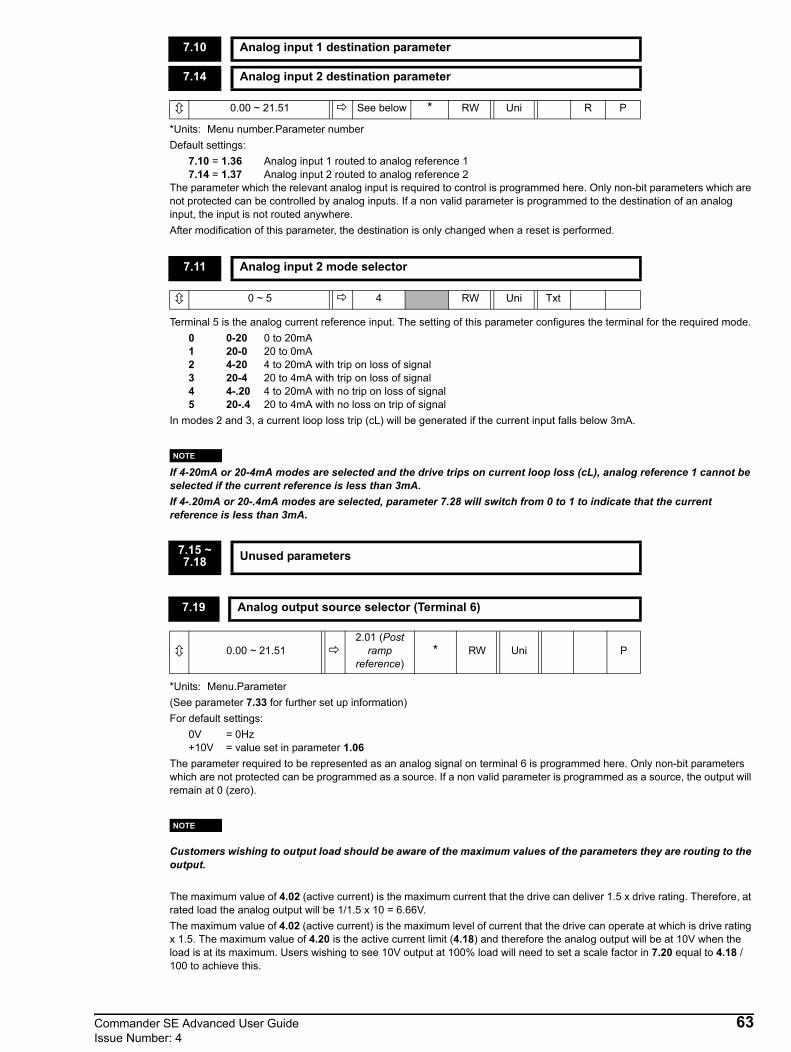
*Units: Menu number.Parameter numberDefault settings:
7.10 = 1.36 Analog input 1 routed to analog reference 17.14 = 1.37 Analog input 2 routed to analog reference 2
The parameter which the relevant analog input is required to control is programmed here. Only non-bit parameters which are not protected can be controlled by analog inputs. If a non valid parameter is programmed to the destination of an analog input, the input is not routed anywhere.After modification of this parameter, the destination is only changed when a reset is performed.
Terminal 5 is the analog current reference input. The setting of this parameter configures the terminal for the required mode.0 0-20 0 to 20mA1 20-0 20 to 0mA2 4-20 4 to 20mA with trip on loss of signal3 20-4 20 to 4mA with trip on loss of signal4 4-.20 4 to 20mA with no trip on loss of signal5 20-.4 20 to 4mA with no loss on trip of signal
In modes 2 and 3, a current loop loss trip (cL) will be generated if the current input falls below 3mA.
If 4-20mA or 20-4mA modes are selected and the drive trips on current loop loss (cL), analog reference 1 cannot be selected if the current reference is less than 3mA.If 4-.20mA or 20-.4mA modes are selected, parameter 7.28 will switch from 0 to 1 to indicate that the current reference is less than 3mA.
*Units: Menu.Parameter(See parameter 7.33 for further set up information)For default settings:
0V = 0Hz+10V = value set in parameter 1.06
The parameter required to be represented as an analog signal on terminal 6 is programmed here. Only non-bit parameters which are not protected can be programmed as a source. If a non valid parameter is programmed as a source, the output will remain at 0 (zero).
Customers wishing to output load should be aware of the maximum values of the parameters they are routing to the output.
The maximum value of 4.02 (active current) is the maximum current that the drive can deliver 1.5 x drive rating. Therefore, at rated load the analog output will be 1/1.5 x 10 = 6.66V.The maximum value of 4.02 (active current) is the maximum level of current that the drive can operate at which is drive rating x 1.5. The maximum value of 4.20 is the active current limit (4.18) and therefore the analog output will be at 10V when the load is at its maximum. Users wishing to see 10V output at 100% load will need to set a scale factor in 7.20 equal to 4.18 / 100 to achieve this.
7.10 Analog input 1 destination parameter
7.14 Analog input 2 destination parameter
0.00 ~ 21.51 See below * RW Uni R P
7.11 Analog input 2 mode selector
0 ~ 5 4 RW Uni Txt
7.15 ~ 7.18 Unused parameters
7.19 Analog output source selector (Terminal 6)
0.00 ~ 21.512.01 (Post
ramp reference)
* RW Uni P
NOTE
NOTE
Commander SE Advanced User Guide 63Issue Number: 4

This parameter can be used to scale the output if so desired. However in most cases it is not necessary as the output is automatically scaled such that when the source parameter is at its maximum, the analog output will be at its maximum. The update time for this output is 21ms.
If analog input 2 is programmed in any of the modes 2 to 5 (see 7.11) then this bit is set if the current input falls below 3mA.This bit can be outputed via a digital output to indicate that the current input is less than 3mA.
This parameter offers a simple control of parameter 7.19 to change the analog output source. It has a range of 0 to 1 for access via the drive’s keypad but 0 to 2 when written to over the serial interface.
0 (Fr) Frequency output Parameter 7.19 = 2.01 (Post ramp speed reference)0V represents 0Hz/0rpm+10V represents the value of parameter 1.06 (Maximum speed clamp)
1 (Ld) Load output Parameter 7.19 = 4.02 (Active current)
2 (AdV) This allows another parameter other than 2.01 and 4.02 to be assigned to 7.19. This parameter must first be set to 2 over serial comms to allow 7.19 to be assigned to any other parameter that the user wishes to display on the analog output.
7.20 Analog output scaling
0.00 ~ 2.50 1.00 RW Uni
7.21 ~ 7.27 Unused parameters
7.28 Current loop loss indicator
0 or 1 RO Bit P
7.29 ~ 7.32 Unused parameters
7.33 Analog output select
0 ~ 2 0 RW Uni Txt R
VoutActive Current
1.5 Drive Rated Current×--------------------------------------------------------------------------- 10×=
64 Commander SE Advanced User GuideIssue Number: 4
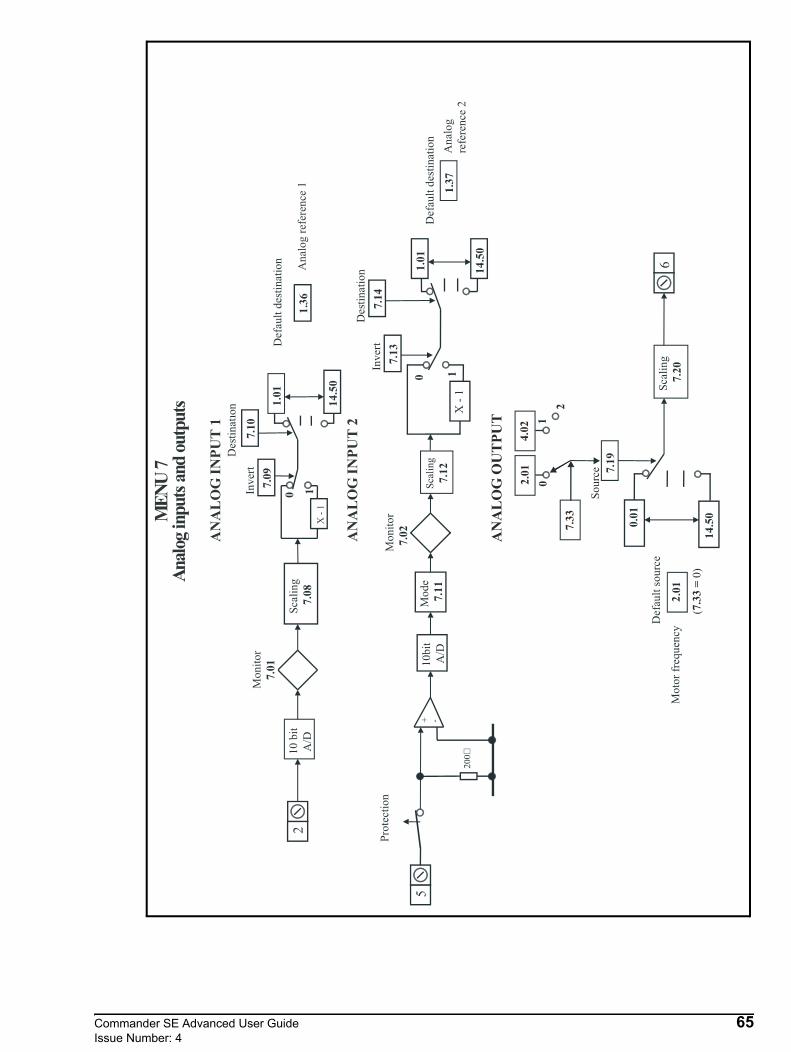
7.1
9
Sca
lin
g
7.2
06
.01
Def
ault
sou
rce
14
.50
0.0
1
10
bit
A/D
20
0
+ -S
cali
ng
7.1
2
0 1
Inv
ert
Mo
nit
or
7.0
2
5M
ode
7.1
1
7.1
3P
rote
ctio
n
X-
1
1.0
1
14
.50
Des
tinat
ion
7.1
4
1.3
7
Def
ault
des
tinat
ion
Des
tin
atio
n
10
bit
A/D
Sca
lin
g
7.0
8
0 1Inv
ert
7.0
91
.01
14.5
0
7.1
0
Def
ault
des
tinat
ion
1.3
6
Mo
nit
or
7.0
1
2
X-
1
An
alo
g
refe
rence
2
Moto
rfr
equ
ency
ME
NU
7A
nal
ogin
puts
and
outp
uts
AN
AL
OG
INP
UT
2
AN
AL
OG
INP
UT
1
An
alo
gre
fere
nce
1
2
(0
)7
.33
=
So
urc
e
7.3
3
2.0
14
.02
01
2
AN
AL
OG
OU
TP
UT
Commander SE Advanced User Guide 65Issue Number: 4

3.8 Menu 8: Digital inputs and outputs
Parameter Range Type Default Setting Update Rate
8.01 Digital input / output 1 (Terminal 8) 0 or 1 RO Bit P L18.02 Digital input 2 (Terminal 9) 0 or 1 RO Bit P L18.03 Digital input 3 (Terminal 10) 0 or 1 RO Bit P L18.04 Digital input 4 (Terminal 11) 0 or 1 RO Bit P L18.05 Digital input 5 (Terminal 12) 0 or 1 RO Bit P L18.06 Digital input 6 (Terminal 13) 0 or 1 RO Bit P L1
8.07 Relay output indicator (Terminals 15 & 16) 0 or 1 RO Bit P L1
8.08~ 8.10 Not used
8.11 Digital input / output 1 invert 0 or 1 RW Bit 0 L18.12 Digital input 2 invert 0 or 1 RW Bit 0 L18.13 Digital input 3 invert 0 or 1 RW Bit 0 L18.14 Digital input 4 invert 0 or 1 RW Bit 0 L18.15 Digital input 5 invert 0 or 1 RW Bit 0 L18.16 Digital input 6 invert 0 or 1 RW Bit 0 L18.17 Relay state invert 0 or 1 RW Bit 0 L18.18~ 8.20 Not used
8.21 Digital input 1 destination / output source 0.00 ~ 21.51 RW Uni R P P10.03 I8.22 Digital input 2 destination 0.00 ~ 21.51 RW Uni R P P06.29 I8.23 Digital input 3 destination 0.00 ~ 21.51 RW Uni R P P06.30 I8.24 Digital input 4 destination 0.00 ~ 21.51 RW Uni R P P06.32 I
8.25 Digital input 5 destination 0.00 ~ 21.51 RW Uni R PReference
select dependant
I
8.26 Digital input 6 destination 0.00 ~ 21.51 RW Uni R PReference
select dependant
I
8.27 Relay source 0.00 ~ 21.51 RW Uni R P P10.01 I8.28 Not used8.29 Logic input polarity 0 ~ 1 RW Bit R P 1 I8.30 Not used8.31 Activate digital output 1 0 ~ 1 RW Bit R 1 L18.32~ 8.38 Not used
8.39 Disable digital inputs 5 and 6 auto selection 0 ~ 1 RW Bit 0 B
8.40 Digital input 6 as thermistor input 0 ~ 1 RW Bit R 0 L1
66 Commander SE Advanced User GuideIssue Number: 4

SummaryTerminals 9 to 13 are five programmable digital inputs. Terminal 8 is a digital output that can also be programmed as a digital input. Also terminal 13 can be programmed as a motor thermistor input.If an External Trip is required, then one of the terminals should be programmed to control the External Trip parameter (10.32) with the invert set to 1 so that the terminal must be made active for the drive not to trip.The digital inputs are sampled every 1.5ms and the digital outputs is updated every 21ms.See Chapter 12 Applications for set-up examples.
This parameter indicates the input state of the terminal if it is set up as an input, or the output state if it is set up as an output. For inputs:
0 = in-active 1 = active
When programmed as a digital output, this terminal is not affected by the logic polarity.
These parameters indicate the input state of the terminal. 0 = in-active 1 = active
This parameter indicates the state of the drive relay. 0= de-energised, 1=energised.
Setting these parameters to a 1 causes the input sense to the destination parameter to be inverted or the output sense from the source parameter to be inverted.
8.01 Digital input / output 1 (Terminal 8)
0 or 1 RO Bit P
8.02 Digital input 2 (Terminal 9)
8.03 Digital input 3 (Terminal 10)
8.04 Digital input 4 (Terminal 11)
8.05 Digital input 5 (Terminal 12)
8.06 Digital input 6 (Terminal 13)
0 or 1 RO Bit P
8.07 Relay output indicator (Terminals 15 and 16)
0 or 1 RO Bit P
8.08~8.10 Unused parameters
8.11 Digital input / output 1 invert
8.12 Digital input 2 invert
8.13 Digital input 3 invert
8.14 Digital input 4 invert
8.15 Digital input 5 invert
8.16 Digital input 6 invert
8.17 Relay state invert
0 or 1 0 RW Bit
Commander SE Advanced User Guide 67Issue Number: 4

*Units: Menu.ParameterDestination parameters define the parameter each of the programmable inputs is to control. Only Bit parameters which are not protected can be controlled by the programmable digital inputs. If a non-valid parameter is programmed, the digital input is not routed anywhere.Source parameters define the parameter to be represented at the digital output terminal or relay. Only Bit parameters can be selected as a source for a digital output. If a non-valid parameter is programmed, then the digital output will remain in the inactive state and the relay will remain in the de-energised state.
This parameter changes the logic polarity on the digital inputs. In its default state the input polarity is positive logic which requires the digital inputs to be driven high to activate the input. When this parameter is set to a 0, the input polarity is negative logic which requires the digital inputs to be pulled low to activate the input.
A change to the logic input polarity will only be implemented if the drive is disabled or tripped and the Stop/Reset key is pressed or a Reset command is given over serial comms. The Run terminals should be open when any change is implemented.
This parameter is set to 1 for Terminal 8 to be an output and set to a 0 for Terminal 8 to be an input.
8.18~8.20 Unused parameters
8.21 Digital input 1 destination / output source
8.22 Digital input 2 destination
8.23 Digital input 3 destination
8.24 Digital input 4 destination
8.25 Digital input 5 destination
8.26 Digital input 6 destination
8.27 Relay source
Source: 0.00 ~ 21.51 * RW Uni R P
TerminalDestination/
source parameter
Function Default parameter Default description Comments
8 8.21 Input destination/Output source 10.03 Zero speed (output)
9 8.22 Input destination 6.29 EnableSee parameter 6.04 for
further set-up information10 8.23 Input destination 6.30 Run Forward11 8.24 Input destination 6.32 Run Reverse12 8.25 Input destination 6.31 Jog Reference select dependant.
See parameter 1.1413 8.26 Input destination 1.41 Local / Remote15 & 16 8.27 Relay source 10.01 Drive Healthy
8.29 Logic input polarity
0 or 1 1 RW Bit R P
8.30 Unused parameter
8.31 Activate digital output 1
0 or 1 1 RW Bit R
NOTE
68 Commander SE Advanced User GuideIssue Number: 4

When this parameter is set to a 0, parameter 8.25 and 8.26 (Terminals 12 and 13 digital inputs) are set up automatically according to the setting of the reference select parameter 1.14 (or 21.03 for motor map 2).
Setting this parameter to 1 stops this auto selection of the digital inputs on terminals 12 and 13 from taking place. This allows the user to determine the function of these terminals.
Setting this bit to a 1 enables terminal 13 to act as a motor thermistor input. In this case, the digital input operation of this terminal is disabled.
Trip Resistance:3kΩReset Resistance:1k8
The drive will not trip if the motor thermistor goes short circuit.
The motor thermistor going short circuit will not damage the drive.
There is not a parameter to display the motor temperature.Connect the motor thermistor between 0V and terminal 13.
When terminal 13 is set-up as a motor thermistor, it is not affected by the logic select. (See parameter 34 or 8.29.)
Connection diagram
8.32~8.38 Unused parameters
8.39 Disable digital inputs 5 and 6 auto selection
0 or 1 0 RW Bit
Parameter 1.14 (or 21.03)
Parameter 8.21 valueTerminal 12 function
Parameter 8.23 valueTerminal 13 function
0 - Analog by terminal 1.41 - Local/Remote 6.31 - Jog1 - Analog voltage 1.45 - Preset select bit 0 1.46 - Preset select bit 12 - Analog current 1.45 - Preset select bit 0 1.46 - Preset select bit 13 - Presets 1.45 - Preset select bit 0 1.46 - Preset select bit 14 - Keypad reference N/A N/A5 - Precision reference N/A N/A
8.40 Digital input 6 as thermistor input
0 or 1 0 RW Bit R
NOTE
NOTE
Commander SE Advanced User Guide 69Issue Number: 4

Inp
ut
/O
utp
ut
monit
or
8.0
1
0 1
Inv
ert
0.0
1
10
.03
Def
ault
sou
rce
Zer
osp
eed
ou
tpu
t
1.0
1
Des
tinat
ion/
sou
rce
(An
yb
it
par
amet
er)
8.2
1
8.3
1
1 0
Inp
ut
/O
utp
ut
sele
ct
0 1
Input
logic
pola
rity
8
8.2
9
01
8.1
1
0.0
1
10
8.2
7
So
urc
e
8.1
7
Inv
ert
Monit
or
8.0
7
10
.01
Def
ault
sou
rce
Dri
ve
hea
lthy
RE
LA
YO
UT
PU
T
15
16
Rel
ay
DIG
ITA
LIN
PU
T/
OU
TP
UT
1:
Posi
tive
logic
0:
Neg
ativ
elo
gic
ME
NU
8A
Dig
ita
lin
pu
ts/
ou
tpu
ts
21
.51
21
.51
21
.51
70 Commander SE Advanced User GuideIssue Number: 4

Monit
or
8.0
2
9 10
11
Input
logic
pola
rity
8.2
9
01
1.0
1
8.2
3
Des
tinat
ion
(An
yb
it
par
amet
er)
Def
ault
des
tinat
ion
6.3
0R
un
Forw
ard
(Def
ined
by
6.0
4)
Monit
or
8.0
3
Inv
ert
0 1
8.1
3
Des
tinat
ion
(An
yb
it
par
amet
er)
1.0
1
8.2
2
Def
ault
des
tinat
ion
6.2
9D
riv
eE
nab
le
(Def
ined
by
6.0
4)
Inv
ert
0 1
8.1
2
Monit
or
8.0
4
Inv
ert
0 1
8.1
4
1.0
1
Des
tinat
ion
(An
yb
it
par
amet
er)
Def
ault
des
tinat
ion
6.3
2R
un
Rev
erse
(Def
ined
by
6.0
4)
8.2
4
Sta
rt/S
top
logic
6.0
4
1:
Posi
tive
logic
0:
Neg
ativ
elo
gic
ME
NU
8B
Dig
ita
lIn
pu
ts
21
.51
21
.51
21
.51
Commander SE Advanced User Guide 71Issue Number: 4

Inv
ert
0 1
8.1
5M
onit
or
8.0
51
.01
8.2
5
Des
tinat
ion
(An
yb
it
par
amet
er)
Def
ault
des
tinat
ion
12
13
Input
logic
pola
rity
8.2
9
01
1.1
4
Ref
eren
ce
sele
ct
01
8.3
9
Dis
able
12
&1
3
auto
mat
icse
t-u
p
Inv
ert
0 1
8.1
6M
onit
or
8.0
61
.01
8.2
6
Des
tinat
ion
Def
ault
des
tinat
ion
6.3
1
Moto
rth
erm
isto
r
sele
ct
8.4
00
1
1:
Posi
tive
logic
0:
Neg
ativ
elo
gic
Jog
(Def
ined
by
1.1
4)
Lo
cal
/R
emo
te
(Def
ined
by
1.1
4)
Dig
ita
lin
pu
ts(c
on
tin
ued
)
21.5
1
21.5
1
1.4
1
72 Commander SE Advanced User GuideIssue Number: 4

3.9 Menu 9: Programmable logic and motorised pot
Parameter Range Type Default Setting Default Rate
9.01 Prog. logic function output indicator 0 or 1 RO Bit P L39.02 Not used9.03 Motorised pot output indicator ±100.0% RO Bi S P L3
9.04 Prog. logic function 1 source parameter
0.00 ~ 21.51 Menu.parameter RW Uni P 0.00 L3
9.05 Prog. logic function source 1 invert 0 or 1 RW Bit 0 L3
9.06 Prog. logic function 2 source parameter
0.00 ~ 21.51 Menu.parameter RW Uni P 0.00 L3
9.07 Prog. logic function source 2 invert 0 or 1 RW Bit 0 L39.08 Prog. logic function output invert 0 or 1 RW Bit 0 L39.09 Prog-logic function delay 0.0 ~ 25.0 secs RW Uni 0 L3
9.10 Prog-logic function destination 0.00 ~ 21.51 Menu.parameter RW Uni R P 0.00 I
9.11~ 9.20 Not used
9.21 Motorised pot zero start select 0 or 1 RW Bit 0 I9.22 Motorised pot bipolar select 0 or 1 RW Bit 0 L39.23 Motorised pot rate 0 ~ 250 secs RW Uni 20 B9.24 Motorised pot scale factor 0.00 ~ 2.50 RW Uni 1.00 B, I
9.25 Motorised pot destination 0.00 ~ 21.51 Menu.parameter RW Uni R P 0.00 I
9.26 Motorised pot. up 0 or 1 RO Bit L39.27 Motorised pot.down 0 or 1 RO Bit L39.28 Motorised pot.reset 0 or 1 RW Bit 0 L3
Commander SE Advanced User Guide 73Issue Number: 4

This parameter indicates the output state of the programmable logic function. The output of the logic function can be routed to the digital output if required, by setting the appropriate digital output source in menu 8.
Indicates the level of the motorised pot prior to scaling. If parameter 9.21 is set to 1 this parameter is set to 0 at power up.
*Units: Menu.ParameterThis source parameter defines the parameter to be sourced into logic input 1 of the programmable logic function 1.Only a bit parameter can be programmed as an input.If both inputs to the logic function are non valid, then the logic output will always be a 0. If one input source is left at its default value of 0.00 or one input source is non valid, its input is taken as 1 so that the valid input on the other input source can pass through the function gate.
Setting this parameter to a 1 causes the input sense from logic function 1 source parameter to be inverted.
*Units: Menu.ParameterThis source parameter defines the parameter to be sourced into logic input 2 of the programmable logic function 1.Only a bit parameter can be programmed as an input.If both inputs to the logic function are non valid, then the logic output will always be a 0. If one input source is left at its default value of 0.00 or one input source is non valid, its input is taken as 1 so that the valid input on the other input source can pass through the function gate.
Setting this parameter to a 1 causes the input sense from logic function 2 source parameter to be inverted.
Setting this parameter to a 1 causes the output from the logic to be inverted.
This parameter introduces a delay into the switching of the logic output of logic function 1. The delay is on an output transition from a 0 to a 1 only, such that there is a delay on the output becoming active, but not on the output becoming inactive. The delay parameters are primarily there to ensure that the output condition is a genuine condition (by being present for a period of time) and not just a temporary one.
9.01 Programmable logic function output indicator
0 or 1 0 RO Bit P
9.02 Unused parameter
9.03 Motorised pot output indicator
±100.0 % RO Bi S P
9.04 Prog. logic function 1 source parameter
0.00 ∼ 21.51 * 0.00 RW Uni P
9.05 Prog. logic function source 1 invert
0 or 1 0 RW Bit
9.06 Prog. logic function 2 source parameter
0.00 ~ 21.51 0.00 * RW Uni P
9.07 Prog. logic function source 2 invert
0 or 1 0 RW Bit
9.08 Prog. logic function output invert
0 or 1 0 RW Bit
9.09 Prog. logic function delay
0.0 ~ 25.0 0 s RW Uni
74 Commander SE Advanced User GuideIssue Number: 4
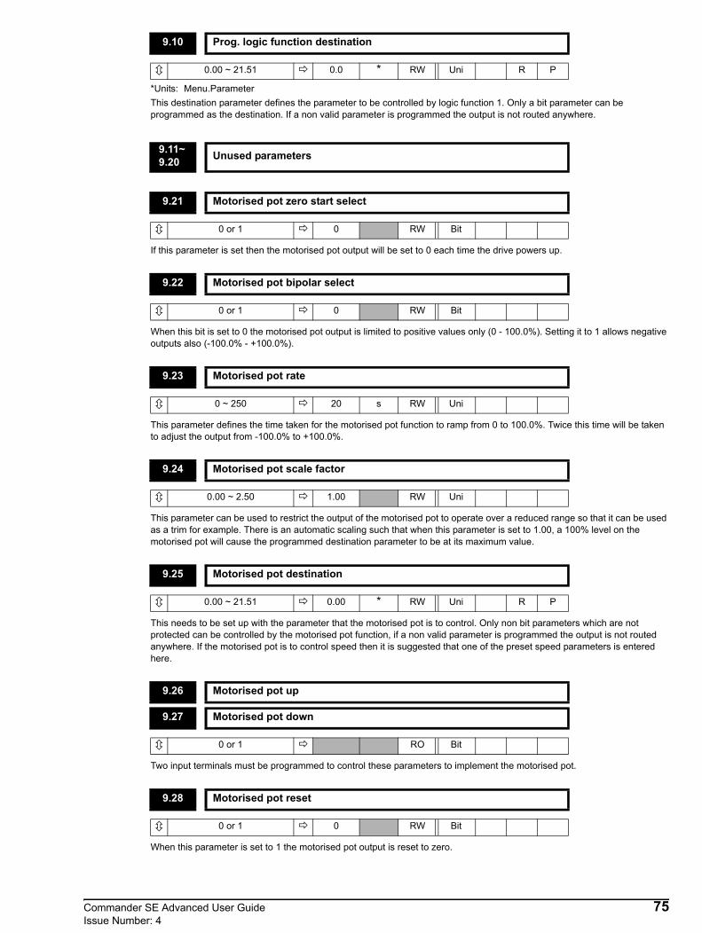
*Units: Menu.ParameterThis destination parameter defines the parameter to be controlled by logic function 1. Only a bit parameter can be programmed as the destination. If a non valid parameter is programmed the output is not routed anywhere.
If this parameter is set then the motorised pot output will be set to 0 each time the drive powers up.
When this bit is set to 0 the motorised pot output is limited to positive values only (0 - 100.0%). Setting it to 1 allows negative outputs also (-100.0% - +100.0%).
This parameter defines the time taken for the motorised pot function to ramp from 0 to 100.0%. Twice this time will be taken to adjust the output from -100.0% to +100.0%.
This parameter can be used to restrict the output of the motorised pot to operate over a reduced range so that it can be used as a trim for example. There is an automatic scaling such that when this parameter is set to 1.00, a 100% level on the motorised pot will cause the programmed destination parameter to be at its maximum value.
This needs to be set up with the parameter that the motorised pot is to control. Only non bit parameters which are not protected can be controlled by the motorised pot function, if a non valid parameter is programmed the output is not routed anywhere. If the motorised pot is to control speed then it is suggested that one of the preset speed parameters is entered here.
Two input terminals must be programmed to control these parameters to implement the motorised pot.
When this parameter is set to 1 the motorised pot output is reset to zero.
9.10 Prog. logic function destination
0.00 ~ 21.51 0.0 * RW Uni R P
9.11~9.20 Unused parameters
9.21 Motorised pot zero start select
0 or 1 0 RW Bit
9.22 Motorised pot bipolar select
0 or 1 0 RW Bit
9.23 Motorised pot rate
0 ~ 250 20 s RW Uni
9.24 Motorised pot scale factor
0.00 ~ 2.50 1.00 RW Uni
9.25 Motorised pot destination
0.00 ~ 21.51 0.00 * RW Uni R P
9.26 Motorised pot up
9.27 Motorised pot down
0 or 1 RO Bit
9.28 Motorised pot reset
0 or 1 0 RW Bit
Commander SE Advanced User Guide 75Issue Number: 4

76 Commander SE Advanced User GuideIssue Number: 4
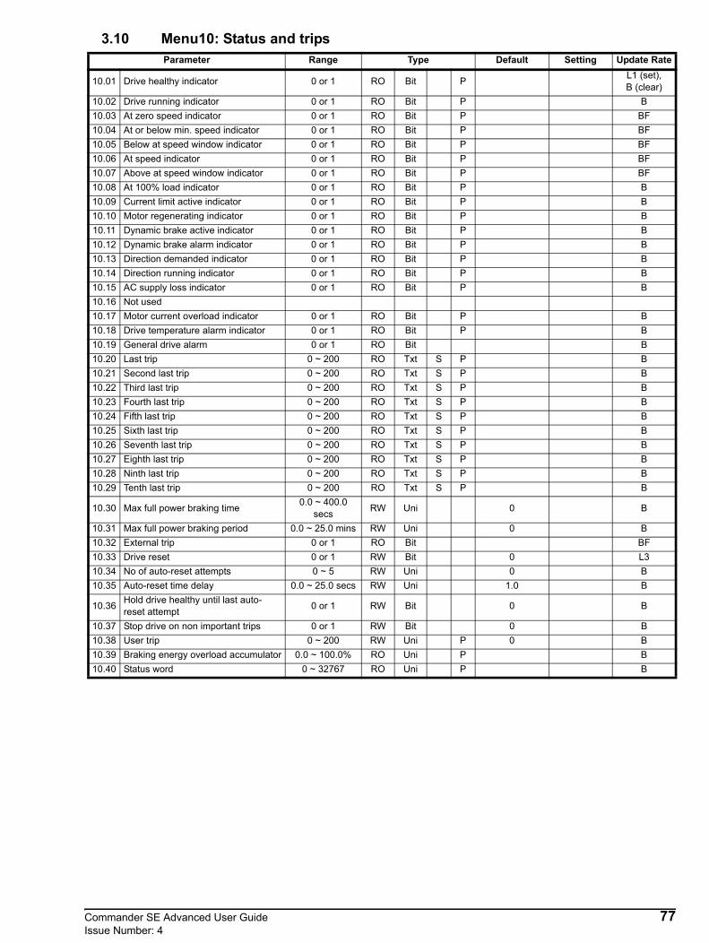
3.10 Menu10: Status and tripsParameter Range Type Default Setting Update Rate
10.01 Drive healthy indicator 0 or 1 RO Bit P L1 (set), B (clear)
10.02 Drive running indicator 0 or 1 RO Bit P B10.03 At zero speed indicator 0 or 1 RO Bit P BF10.04 At or below min. speed indicator 0 or 1 RO Bit P BF10.05 Below at speed window indicator 0 or 1 RO Bit P BF10.06 At speed indicator 0 or 1 RO Bit P BF10.07 Above at speed window indicator 0 or 1 RO Bit P BF10.08 At 100% load indicator 0 or 1 RO Bit P B10.09 Current limit active indicator 0 or 1 RO Bit P B10.10 Motor regenerating indicator 0 or 1 RO Bit P B10.11 Dynamic brake active indicator 0 or 1 RO Bit P B10.12 Dynamic brake alarm indicator 0 or 1 RO Bit P B10.13 Direction demanded indicator 0 or 1 RO Bit P B10.14 Direction running indicator 0 or 1 RO Bit P B10.15 AC supply loss indicator 0 or 1 RO Bit P B10.16 Not used10.17 Motor current overload indicator 0 or 1 RO Bit P B10.18 Drive temperature alarm indicator 0 or 1 RO Bit P B10.19 General drive alarm 0 or 1 RO Bit B10.20 Last trip 0 ~ 200 RO Txt S P B10.21 Second last trip 0 ~ 200 RO Txt S P B10.22 Third last trip 0 ~ 200 RO Txt S P B10.23 Fourth last trip 0 ~ 200 RO Txt S P B10.24 Fifth last trip 0 ~ 200 RO Txt S P B10.25 Sixth last trip 0 ~ 200 RO Txt S P B10.26 Seventh last trip 0 ~ 200 RO Txt S P B10.27 Eighth last trip 0 ~ 200 RO Txt S P B10.28 Ninth last trip 0 ~ 200 RO Txt S P B10.29 Tenth last trip 0 ~ 200 RO Txt S P B
10.30 Max full power braking time 0.0 ~ 400.0 secs RW Uni 0 B
10.31 Max full power braking period 0.0 ~ 25.0 mins RW Uni 0 B10.32 External trip 0 or 1 RO Bit BF10.33 Drive reset 0 or 1 RW Bit 0 L310.34 No of auto-reset attempts 0 ~ 5 RW Uni 0 B10.35 Auto-reset time delay 0.0 ~ 25.0 secs RW Uni 1.0 B
10.36 Hold drive healthy until last auto-reset attempt 0 or 1 RW Bit 0 B
10.37 Stop drive on non important trips 0 or 1 RW Bit 0 B10.38 User trip 0 ~ 200 RW Uni P 0 B10.39 Braking energy overload accumulator 0.0 ~ 100.0% RO Uni P B10.40 Status word 0 ~ 32767 RO Uni P B
Commander SE Advanced User Guide 77Issue Number: 4

This parameter indicates whether the drive has tripped or not. If parameter 10.36 is set to 1, this bit will be at 1 in a tripped state if an auto reset is going to occur. Once the programmed number of auto resets have occurred the next trip will cause this bit to be cleared.
When a reset is performed to reset a drive trip, there is a 1 second delay before the drive healthy relay contacts will change to indicate that the drive is healthy. This 1 second delay is in the drive’s sequencer software and cannot be changed.
This parameter is set if the inverter output is active
This bit is set to 1 when the absolute value of the ramp output is at or below the threshold programmed into parameter 3.05.
In bipolar mode (1.10 = 1) this parameter is the same as zero speed (10.03).In unipolar mode this parameter is set if the absolute value of the ramp output is at or below minimum speed + 0.5Hz. Minimum speed is defined by parameter 1.07.This parameter is only set if the drive is running.
This parameter is set when the absolute value of the ramp output is below the 'At speed' window. The 'At speed' window is Set speed ±(Parameter 3.06 / 2). Parameter is only set if drive is running.
This parameter is set when the absolute value of the ramp output is within the 'At speed' window which is Set speed ±(Parameter 3.06 / 2). Parameter is only set if drive is running.
This parameter is set when the absolute value of the ramp output is above the 'At speed' window. The 'At speed' window is Set speed ±(Parameter 3.06 / 2). Parameter is only set if drive is running.
Set if active current (4.02) is greater or equal to rated active current (see Menu 4: Current control for definition of rated active current).
This parameter is set if the normal current limit is active.
10.01 Drive healthy indicator
0 or 1 RO Bit P
10.02 Drive running indicator
0 or 1 RO Bit P
10.03 At zero speed indicator
0 or 1 RO Bit P
10.04 At or below min. speed indicator
0 or 1 RO Bit P
10.05 Below at speed window indicator
0 or 1 RO Bit P
10.06 At speed indicator
0 or 1 RO Bit P
10.07 Above at speed window indicator
0 or 1 RO Bit P
10.08 At 100% load indicator
0 or 1 RO Bit P
10.09 Current limit active indicator
0 or 1 RO Bit P
NOTE
78 Commander SE Advanced User GuideIssue Number: 4

This parameter is set if the output bridge is transferring power from the motor to the DC Bus.
This parameter is set when power is being dumped in the optional braking resistor if fitted.
This flag is set when the dynamic brake is active and the braking energy accumulator is greater than 75%.
This parameter is a 1 if the pre-ramp reference is negative (reverse), and is a 0 if pre-ramp reference is positive (forward).
This parameter is a 1 if the post-ramp reference is negative (reverse), and a 0 if post-ramp reference is positive (forward).
Indicates a loss of input supply to the drive.
This flag is set if the motor active current is larger than 105% of the programmed motor rated active current and the overload accumulator is greater than 75% to warn that if the motor current is not reduced the drive will trip on an Ixt overload or will reduce the current automatically depending on the protection mode programmed in parameter 4.16.
This flag is set if the IGBT junction temperature calculated from the drive thermal model is above 135°C, or if the heatsink temperature has made the switching frequency decrease.The following table indicates how the switching frequency is controlled.
*Commander SE Size 4 >100°C
The switching frequency and drive thermal model are updated once per second. Whenever the drive has reduced the switching frequency, this alarm is set. Also, when this alarm has been set, the drive’s display will flash ‘hot’. Also see parameters 5.18 and 7.04.
10.10 Motor regenerating indicator
0 or 1 RO Bit P
10.11 Dynamic brake active indicator
0 or 1 RO Bit P
10.12 Dynamic brake alarm indicator
0 or 1 RO Bit P
10.13 Direction demanded indicator
0 or 1 RO Bit P
10.14 Direction running indicator
0 or 1 RO Bit P
10.15 AC supply loss indicator
0 or 1 RO Bit P
10.16 Unused parameter
10.17 Motor current overload indicator
0 or 1 RO Bit P
10.18 Drive temperature alarm indicator
0 or 1 RO Bit P
Drive condition ActionHeatsink >95°C* Trip driveHeatsink >92°C Reduce switching frequency to 3kHzHeatsink >88°C Reduce switching frequency to 6kHz
Heatsink <85°C and IGBT temperature at new switching frequency <135°C Allow an increase in the switching frequency
IGBT temperature >135°C Reduce switching frequency. If it is 3kHz minimum, trip drive
Commander SE Advanced User Guide 79Issue Number: 4

This flag is set if any of the drive alarms are active, i.e. Drive temperature alarm, Overload alarm or Dynamic brake alarm. 10.19 = 10.18 or 10.17 or 10.12.
Parameter 10.20 is the most recent trip and 10.29 the oldest. When a new trip occurs all the parameters move down one, the new trip is put in 10.20 and the oldest trip disappears from the bottom. Possible trips are:
10.19 General drive alarm
0 or 1 RO Bit P
10.20 Last trip
10.21 Second last trip
10.22 Third last trip
10.23 Fourth last trip
10.24 Fifth last trip
10.25 Sixth last trip
10.26 Seventh last trip
10.27 Eighth last trip
10.28 Ninth last trip
10.29 Tenth last trip
0 ~ 200 RO Uni Txt S P
Trip Code TripNumber Condition Possible Cause
UU 1 DC link under voltageLow AC supply voltageLow DC link voltage when supplied by external DC power supply
OU 2 DC link over voltage Excessive inertia in the machine during decelerationDeceleration rate set too fast for inertia of machine
OI.AC** 3 AC instantaneous over current trip
Insufficient ramp timesPhase to phase or phase to earth short-circuit at drive outputDrive requires autotuning to motor or motor connections changed, re-autotune drive to motor (see parameter 5.12)
OI.br** 4 Overcurrent on braking IGBTExcessive current in braking resistorBraking resistor value too small(Does not apply to Size 1 units)
Et 6 External trip External trip terminal opened (when programmed)
O.SP 7 Over speedExcessive motor speed (typically caused by the mechanical load driving the motor) Standard ramp voltage set too low, see parameter 2.08
tunE 18 Auto-tune failure Motor loaded or no motor connected
It.br 19 Ixt on braking resistor Excessive braking resistor energy(Does not apply to Size 1 units)
It.AC 20 Motor overload on current x time
Too much mechanical loadHigh impedance phase to phase or phase to earth short circuit at drive output drive requires autotuning to motor. Motor or motor connections changed, re-autotune drive to Motor (see parameter 5.12)
Oht1 21 Overheat Overheat thermal model
Oht2† 22 Overheat (heatsink thermistor) Temperature exceeds 95°C (203°F), 100°C (212°C) for Size 4
th 24 Over temperature (Motor thermistor) Excessive motor temperatureO.Ld1* 26 +24V or digital output overload Excessive load or short circuit on +24V output
80 Commander SE Advanced User GuideIssue Number: 4
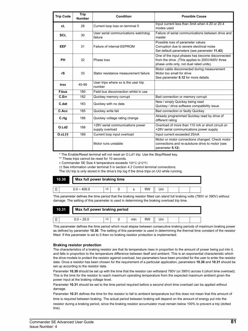
* The Enable/Reset terminal will not reset an O.Ld1 trip. Use the Stop/Reset key.** These trips cannot be reset for 10 seconds. † Commander SE Size 4 temperature exceeds 100°C (212°F)†† See information under terminal 5 in section 4.2 Control terminal connections.The UU trip is only stored in the drive’s trip log if the drive trips on UU while running.
This parameter defines the time period that the braking resistor fitted can stand full braking volts (780V or 390V) without damage. The setting of this parameter is used in determining the braking overload trip time.
This parameter defines the time period which must elapse between consecutive braking periods of maximum braking power as defined by parameter 10.30. The setting of this parameter is used in determining the thermal time constant of the resistor fitted. If this parameter is set to 0 then no braking resistor protection is implemented.
Braking resistor protectionThe characteristics of a braking resistor are that its temperature rises in proportion to the amount of power being put into it, and falls in proportion to the temperature difference between itself and ambient. This is an exponential characteristic which the drive models to protect the resistor against overload, two parameters have been provided for the user to enter the resistor data. Once a resistor has been chosen for the requirement of a particular application, parameters 10.30 and 10.31 should be set up according to the resistor data.Parameter 10.30 should be set up with the time that the resistor can withstand 780V (or 390V) across it (short time overload). This is the time for the resistor to reach maximum operating temperature from the expected maximum ambient given the power input at the braking voltage level.Parameter 10.31 should be set to the time period required before a second short time overload can be applied without damage.Parameter 10.31 defines the time for the resistor to fall to ambient temperature but this does not mean that this amount of time is required between braking. The actual period between braking will depend on the amount of energy put into theresistor during a braking period, since the braking resistor accumulator must remain below 100% to prevent a trip (dotted line).
cL 28 Current loop loss on terminal 5 Input current less than 3mA when 4-20 or 20-4 modes used
SCL 30 User serial communications watchdog failure
Failure of serial communications between drive and master
EEF 31 Failure of internal EEPROMPossible loss of parameter valuesCorruption due to severe electrical noiseSet default parameters (see parameter 11.43)
PH 32 Phase lossOne of the input phases has become disconnected from the drive. (This applies to 200V/400V three phase units only, not dual rated units).
rS 33 Stator resistance measurement failureMotor cable disconnected during measurementMotor too small for driveSee parameter 5.12 for more details
trxx 40-99 User trips where xx is the user trip number
F.bus 180 Field bus disconnection whilst in useC.Err 182 Quickey memory corrupt Bad connection or memory corrupt
C.dat 183 Quickey with no data New / empty Quickey being readQuickey / drive software compatibility issue
C.Acc 185 Quickey write fail Bad connection or faulty Quickey
C.rtg 186 Quickey voltage rating change Already programmed Quickey read by drive of different rating
O.Ld2 188 +28V serial communications power supply overload
Overload of more than 110 mA or short circuit on +28V serial communications power supply
O.cL†† 189 Current loop input overload Input current exceeded 25mA
Motor runs unstableMotor or motor connections changed. Check motor connections and re-autotune drive to motor (see parameter 5.12)
10.30 Max full power braking time
0.0 ~ 400.0 0 s RW Uni
10.31 Max full power braking period
0.0 ~ 25.0 0 min RW Uni
Trip Code TripNumber Condition Possible Cause
Commander SE Advanced User Guide 81Issue Number: 4

If this flag is set to 1 then the drive will trip (Et). An inversion of the input logic must also be programmed such that the terminal must be active to prevent a trip.Although this parameter is defined as Read Only, it can be programmed as a destination for a digital input. It cannot be written to over serial communications.
A 0 - 1 change on this parameter will cause a drive reset. If a drive reset terminal is required on the drive the required terminal must be programmed to control this bit.
If this parameter is set to zero then no auto reset will ever occur. Any other value will cause the drive to automatically reset following a trip for the number of times programmed. Parameter 10.35 defines the time between the trip and the auto reset. The reset count is only incremented when the trip is the same as the previous trip, otherwise it is reset to 0. When the reset count reaches the programmed value, any further trip of the same value will not incur an auto-reset.If there has been no trip for 2 minutes then the reset count is cleared.Auto reset will not occur on an External trip (Et).
This parameter defines the time between a trip and an auto reset subject to the minimum trip time for IGBT overcurrent trips.
If this parameter is 0 then parameter 10.01 (Drive healthy) is cleared every time the drive trips regardless of any auto-reset that may occur. When this parameter is set the Inverter healthy indication is not cleared on a trip if an auto-reset is going to occur.
If this parameter is set, the drive will stop before tripping on non important trips. Non important trips are cL, EEF error when saving data, O.Ld, and PH.
10.32 External trip
0 or 1 RO Bit
10.33 Drive reset
0 or 1 0 RW Bit
10.34 No. of auto reset attempts
0 ~ 5 0 RW Uni
10.35 Auto reset time delay
0 ~ 25.0 1.0 s RW Uni
10.36 Hold drive healthy until last auto-reset attempt
0 or 1 0 RW Bit
10.37 Stop drive on non important trips
0 or 1 0 RW Bit
0
100
Overloadaccumulator%
t10.3010.31
10.39
82 Commander SE Advanced User GuideIssue Number: 4

This parameter is used to generate user trips over the serial comms. Valid trip codes are numbers between the largest trip code used by the drive and 99. Writing a trip code that already exists causes that trip to occur. User generated trips will be indicated by trxx in the trip log where xx is the trip code.Users wishing to reset the drive over the serial comms can do so by writing a value of 100 to this parameter.See Chapter 12 Applications for an example of using the user trip.
This parameter gives an indication of braking resistor temperature based on the model described above (see 10.30 and 10.31). Zero indicates the resistor is close to ambient and 100% is the maximum temperature (trip level).
This parameter is for use by a serial comms interface. The value of this parameter is the addition of the drive read only bits with binary weighting as follows:
10.38 User trip
0 ~ 200 0 RW Uni P
10.39 Braking energy overload accumulator
0.0 ~ 100.0 % RO Uni P
10.40 Status word
0 ~ 32767 RO Uni P
10.01 20 10.09 28
10.02 21 10.10 29
10.03 22 10.11 210
10.04 23 10.12 211
10.05 24 10.13 212
10.06 25 10.14 213
10.07 26 10.15 214
10.08 27
Commander SE Advanced User Guide 83Issue Number: 4

3.11 Menu 11: MiscellaneousParameter Range Type Default Setting Update Rate
11.01~ 11.20 Not used
11.21 Parameter scaling 0.00 ~ 99.99 RW Uni 1.00 B
11.22 Parameter displayed at power up select 0 or 1 RW Bit 0 B
11.23 Serial comms address 0.0 ~ 24.7 Group.Unit RW Uni 1.1 BF
11.24 Serial comms mode(0) Ansi(1) rtu
(2) F.busRW Txt R 0 BF, L1
11.25 Serial comms baud rate
(0) 2.4(1) 4.8(2) 9.6
(3) 19.2
RW Txt (1)4.8 BF
11.26 Serial comms minimum transmit delay 0-250mS RW Uni 20 BF, L1
11.27~ 11.28 Not used
11.29 Drive software version 1.00 ~ 9.99 RO Uni P I11.30 User security code 0 ~ 9999 RW Uni S P 0 B11.31 Not used11.32 Drive rated continuous current 1.50 ~ 70.0A RO Uni P I11.33 Drive voltage rating 240 ~ 480V RO Uni P I11.34 Drive software sub version 0 ~ 99 RO Uni P I11.35 Drive DSP software version 0 ~ 9.9 RO Uni P B11.36~ 11.40 Not used
11.41 Status mode timeout 0 ~ 250secs RW Uni P 240 B
11.42 Parameter cloning
(0) no(1) rEAD(2) Prog(3) Auto(4) boot
RW Uni Txt R (0)no B
11.43 Load default parameters
(0) no(1) Eur(2) USA(3) br.Eu(4) br.US
RW Uni Txt R (0)no B
11.44 Security status(0) L1(1) L2(2) Loc
RW Uni Txt R (0)L1 B
11.45 Select motor 2 parameters 0 or 1 RW Bit 0 B
84 Commander SE Advanced User GuideIssue Number: 4
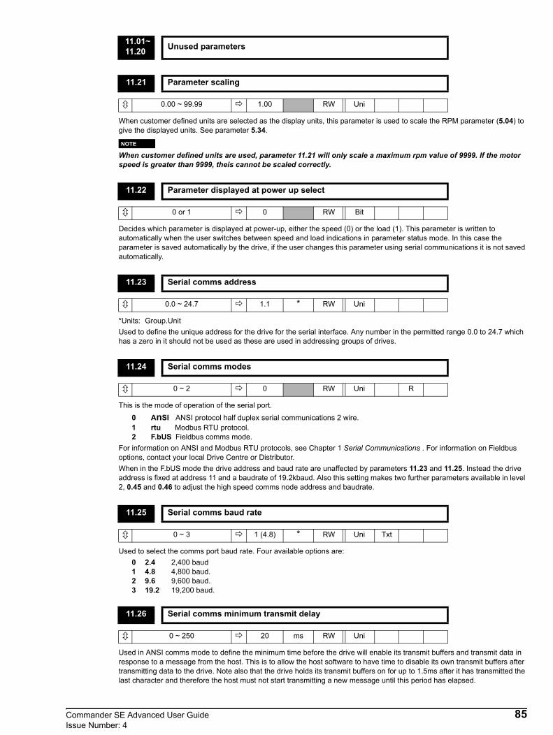
When customer defined units are selected as the display units, this parameter is used to scale the RPM parameter (5.04) to give the displayed units. See parameter 5.34.
When customer defined units are used, parameter 11.21 will only scale a maximum rpm value of 9999. If the motor speed is greater than 9999, theis cannot be scaled correctly.
Decides which parameter is displayed at power-up, either the speed (0) or the load (1). This parameter is written to automatically when the user switches between speed and load indications in parameter status mode. In this case the parameter is saved automatically by the drive, if the user changes this parameter using serial communications it is not saved automatically.
*Units: Group.UnitUsed to define the unique address for the drive for the serial interface. Any number in the permitted range 0.0 to 24.7 which has a zero in it should not be used as these are used in addressing groups of drives.
This is the mode of operation of the serial port.
0 AnSI ANSI protocol half duplex serial communications 2 wire.1 rtu Modbus RTU protocol.2 F.bUS Fieldbus comms mode.
For information on ANSI and Modbus RTU protocols, see Chapter 1 Serial Communications . For information on Fieldbus options, contact your local Drive Centre or Distributor.When in the F.bUS mode the drive address and baud rate are unaffected by parameters 11.23 and 11.25. Instead the drive address is fixed at address 11 and a baudrate of 19.2kbaud. Also this setting makes two further parameters available in level 2, 0.45 and 0.46 to adjust the high speed comms node address and baudrate.
Used to select the comms port baud rate. Four available options are:0 2.4 2,400 baud1 4.8 4,800 baud.2 9.6 9,600 baud.3 19.2 19,200 baud.
Used in ANSI comms mode to define the minimum time before the drive will enable its transmit buffers and transmit data in response to a message from the host. This is to allow the host software to have time to disable its own transmit buffers after transmitting data to the drive. Note also that the drive holds its transmit buffers on for up to 1.5ms after it has transmitted the last character and therefore the host must not start transmitting a new message until this period has elapsed.
11.01~11.20 Unused parameters
11.21 Parameter scaling
0.00 ~ 99.99 1.00 RW Uni
11.22 Parameter displayed at power up select
0 or 1 0 RW Bit
11.23 Serial comms address
0.0 ~ 24.7 1.1 * RW Uni
11.24 Serial comms modes
0 ~ 2 0 RW Uni R
11.25 Serial comms baud rate
0 ~ 3 1 (4.8) * RW Uni Txt
11.26 Serial comms minimum transmit delay
0 ~ 250 20 ms RW Uni
NOTE
Commander SE Advanced User Guide 85Issue Number: 4

Indicates the version of drive software fitted
If any number other than 0 is programmed in this parameter a user security will be applied. When a user security code has been programmed, none of the parameters in the basic parameter set can be altered.
This parameter indicates the drives continuous current rating in amps.
This parameter indicates the voltage rating of the drive.
Indicates the sub-version of drive software fitted.
Indicates the version of DSP software fitted.
Sets the timeout in seconds for the drive display to revert to status mode from parameter mode following no action on the keypad.
11.27~11.28 Unused parameters
11.29 Drive software version
1.00 ~ 9.99 RO Uni P
11.30 User security code
0 ~ 9999 0 RW Uni S P
11.31 Unused parameter
11.32 Drive rated continuous current
1.50 ~ 70.00 A RO Uni P
11.33 Drive voltage rating
240 ~ 480 V RO Uni P
11.34 Drive software sub version
0 ~ 99 RO Uni P
11.35 Drive DSP software version
0 ~ 9.9 RO Uni P
11.36~11.40 Unused parameters
11.41 Status mode timeout
0 ~ 250 240 s RW Uni P
86 Commander SE Advanced User GuideIssue Number: 4

Alternatives to pressing the STOP/RESET when in rEAd or Prog modes:• Set parameter 10.33 to a 1 via serial communications• Set parameter 10.38 to 100 via serial communications• Toggle a terminal programmed as a reset terminal
Any parameter values that have been changed via serial communications but not stored in the drives EEPROM memory will not be stored in the Quickey
When the drive parameters are stored to the Quickey, if the current mode is rEAd or Prog, it is stored in the Quickey as no. If the current mode is AutO or boot, these are stored as AutO or boot.
The Quickey memory contains drive size specific information. If the contents of the Quickey are copied to a drive of a different rating to that previously programmed, the drive will trip with the code C.rtg. This signifies that all of the parameters apart from the drive rating specific parameters have been copied from the Quickey.
The Quickey should only be installed or removed when power to the drive has been switched off.
Different drive ratingsThe cloning key can be used to copy parameters between drives with different ratings but certain rating dependant parameters are not copied to the cloned drive, but are still stored within the cloning key.
Drive Rating has changed
In the event that the ratings are different the parameters are firstly written to the drive and then the drive will trip with C.rtg.
11.42 Parameter cloning
0 ~ 4 0 RW Uni Txt R
0 no Do nothing1 rEAd When this is set and the user performs a drive reset by pressing the STOP/RESET key
while the drive is disabled (ih), tripped (tr) or on stand-by (rd), the Quickey contents will be copied to the drive and parameter 11.42 reset to no (0). These parameters are then saved automatically by the drive.
2 Prog When this is set and the user performs a drive reset by pressing the STOP/RESET key, the Quickey contents will be updated with the current drive EEPROM memory parameter settings. Parameter 11.42 is also reset to no (0).
3 AutO When this is set and the user performs a parameter save by pressing the mode button after adjusting a parameter value, the drives current EEPROM memory parameter settings are saved in the Quickey.
4 boot When this is set, it provides exactly the same functionality as Auto but in addition it will overwrite the drives EEPROM memory parameter settings with the Quickey parameter settings when the drive is powered up. These parameters are then automatically saved by the drive. This mode provides a very fast and efficient way of re-programming a number of drives.
Parameter Description02.08 Standard ramp voltage04.07 Current Limit04.08 Torque Reference05.07 Motor 1 rated current06.06 Injection braking level05.09 Motor 1 rated voltage05.17 Motor 1 stator resistance05.23 Motor 1 voltage offset21.07 Motor 2 rated current21.09 Motor 2 rated voltage21.12 Motor 2 stator resistance21.13 Motor 2 voltage offset
NOTE
NOTE
NOTE
NOTE
Commander SE Advanced User Guide 87Issue Number: 4

If this parameter is set to a non-zero value and the drive reset the selected default parameters will automatically be loaded.0 no do nothing1 Eur Load European 50Hz defaults2 USA Load USA 60Hz defaults3 br.Eu Load European 50Hz Defaults With Brake Function4 br.US Load USA 60Hz Default With Brake Function
This read write parameter defines the level of security for menu 00 L1 Only the first ten parameters can be accessed1 L2 All parameters in level 1 and level 2 can be accessed2 Loc Lock security, so that the security code must be entered before a parameter can be edited and set security
status to L1. For this to be acted upon a Drive Reset must be performed.
When this bit is set to 1 the Motor two parameter set becomes active. The following parameter changes are made:
Changes will only be implemented when the drive is in a disabled state. When the second motor parameter set is active, the decimal point in the centre of the two digit display will be illuminated and 21.15 will change from logic 0 to 1.
11.43 Load default parameters
0 ~ 4 0 RW Uni Txt R
11.44 Security status
0 ~ 2 0 RW Uni Txt R
11.45 Select motor 2 parameters
0 or 1 0 RW Bit
Motor 1 Motor 2Maximum Speed 1.06 21.01Minimum Speed 1.07 21.02Reference Select 1.14 21.03Acceleration rate 2.11 21.04Deceleration Rate 2.21 21.05Rated Frequency 5.06 21.06Rated Current 5.07 21.07Rated RPM 5.08 21.08Rated Voltage 5.09 21.09Rated PF 5.10 21.10No of Poles 5.11 21.11Stator resistance 5.17 21.12Voltage Offset 5.23 21.13Machine Inductance 5.24 21.14Motor Map 2 Active - 21.25
88 Commander SE Advanced User GuideIssue Number: 4

3.12 Menu 12: Threshold detectorParameter Range Type Default Setting Update Rate
12.01 Threshold detector output indicator 0 or 1 RO Bit P L3
12.02 Not used
12.03 Threshold detector source 0.00 ~ 21.51 Menu.Parameter RW Uni P 0.00 B
12.04 Threshold detector level 0.0 ~ 100.0% RW Uni 0.0 L312.05 Threshold detector hysteresis 0.0 ~ 25.0% RW Uni 0.0 L312.06 Threshold detector output invert 0 or 1 RW Bit 0 L3
12.07 Threshold detector destination 0.00 ~ 21.51 Menu.Parameter RW Uni R P 0.00 I
12.08 Variable selector source 1 0.00 ~ 21.51 Menu.Parameter RW Uni R P 0.00 I
12.09 Variable selector source 2 0.00 ~ 21.51 Menu.Parameter RW Uni R P 0.00 I
12.10 Variable select bit 0 or 1 RW Bit 0 L3
12.11 Variable selector destination 0.00 ~ 21.51 Menu.Parameter RW Uni R P 0.00 I
Commander SE Advanced User Guide 89Issue Number: 4

This menu contains a programmable threshold and a variable selector. The programmable threshold can be used to change the drives action or output a signal at a predetermined level of the input signal. For example it can be used to change a ramp rate at a pre-programmed frequency. The variable selector allows the user to be able to set up two different values for a particular parameter and switch between them.Viewing the block diagram of Menu 12 will help in understanding the functions of the following parameters.See Chapter 12 Applications for threshold detector and variable selector set up examples.
This parameter indicates whether the threshold input variable is above (1) or below (0) the programmed threshold.
*Units: Menu.ParameterDefines the parameter to be input to the programmable threshold.The absolute value of the source variable is taken as input to the threshold comparator. Only non-bit parameters can be programmed as a source. If a non valid parameter is programmed the input value is taken as 0.
This is the user defined threshold level entered as a percentage of the source maximum.
This parameter defines the band within which no change will occur on the output. The upper limit for switching is therefore Level + Hyst/2 and the lower level will be Level - Hyst/2.
This parameter is used to invert the logic state of the threshold output if required.
*Units: Menu.ParameterThis parameter defines the parameter which is to be controlled by the threshold comparator. Only Bit parameters which are not protected can be setup as a destination. If a non valid parameter is programmed the output is not routed anywhere.
*Units: Menu.ParameterDefines the parameters which are to be switched by the variable selector block. These can be bit variables or non bit variables but not a mixture of both. Also the output parameter programmed must be the same type as the destination parameter, if not they are always read as zero. Please be aware when programming a reference to a variable source select, if the reference is a percentage, then the variable source treats the percentage as a whole number e.g. 50.0% of reference = 50.0Hz.
12.01 Threshold detector output indicator
0 or 1 RO Bit P
12.02 Unused parameter
12.03 Threshold detector source
0.00 ~ 21.51 0.0 * RW Uni P
12.04 Threshold detector level
0.0 ~ 100.0 0 % RW Uni
12.05 Threshold detector hysteresis
0.0 ~ 25.0 0 % RW Uni
12.06 Threshold detector output invert
0 or 1 0 RW Bit
12.07 Threshold detector destination
0.00 ~ 21.51 0.00 * RW Uni R P
12.08 Variable selector source 1
12.09 Variable selector source 2
0.00 ~ 21.51 0.00 * RW Uni R P
90 Commander SE Advanced User GuideIssue Number: 4

This bit is used to select one of two variables. Users wishing to make the change by external control should program a terminal to control this bit.
*Units: Menu.ParameterThis parameter defines the parameter that the variable selector is to control. Only parameters which are not protected can be setup as a destination. If a non valid parameter is programmed the output is not routed anywhere.
12.10 Variable select bit
0 or 1 0 RW Bit
12.11 Variable selector destination
0.00 ~ 21.51 0.00 * RW Uni R P
Commander SE Advanced User Guide 91Issue Number: 4

12.0
4
Lev
el
12.0
5
Hyst
eres
is
0.0
1
12.0
3
So
urc
e
Th
resh
old
exce
eded
12.0
1
1 0
12.0
6
Inv
ert
1.0
1
Des
tinat
ion
(An
yb
it
par
amet
er)
12.0
7
Hyst
eres
is
12.0
5
Thre
shold
exce
eded
12.0
1
12.0
4=
%of
max
imum
of
12.0
3
Th
resh
old
sou
rce
12.0
3
ME
NU
12
AP
rog
ram
ma
ble
thre
sho
ld
21
.51
21
.51
92 Commander SE Advanced User GuideIssue Number: 4
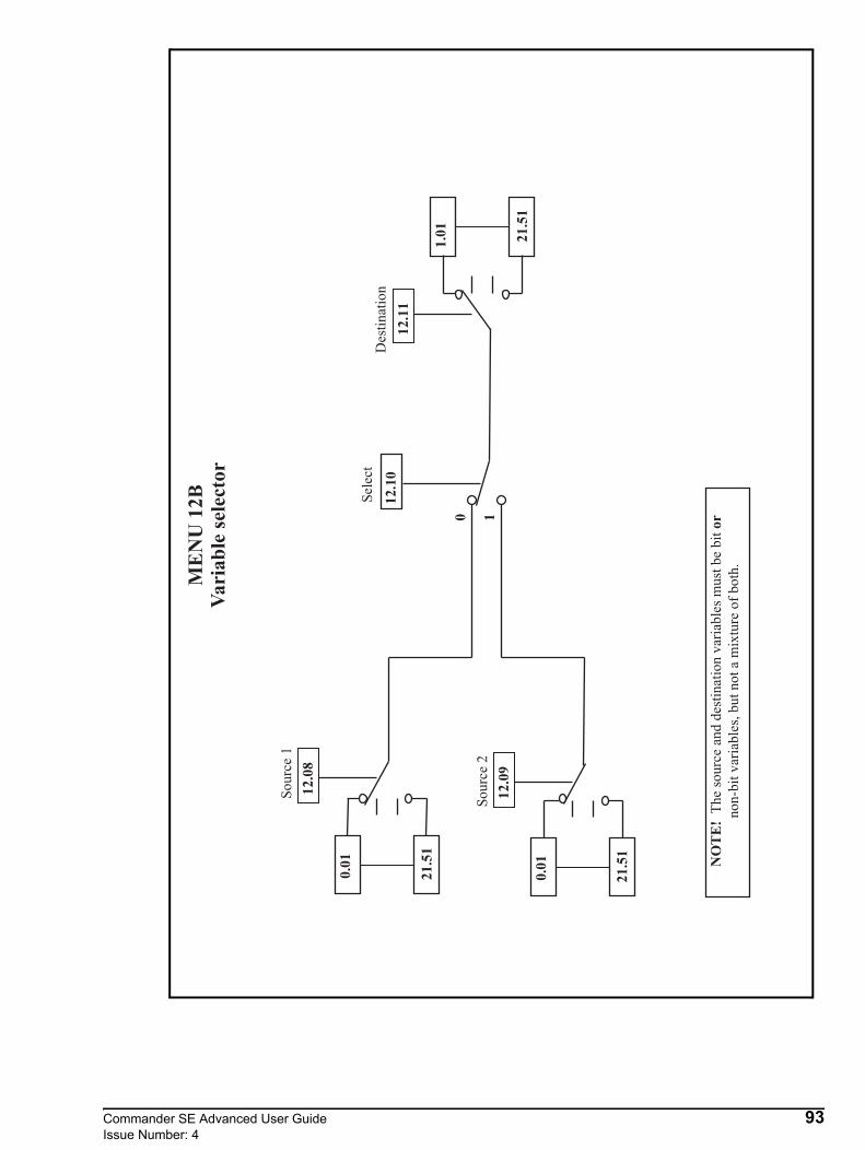
Commander SE Advanced User Guide 93Issue Number: 4
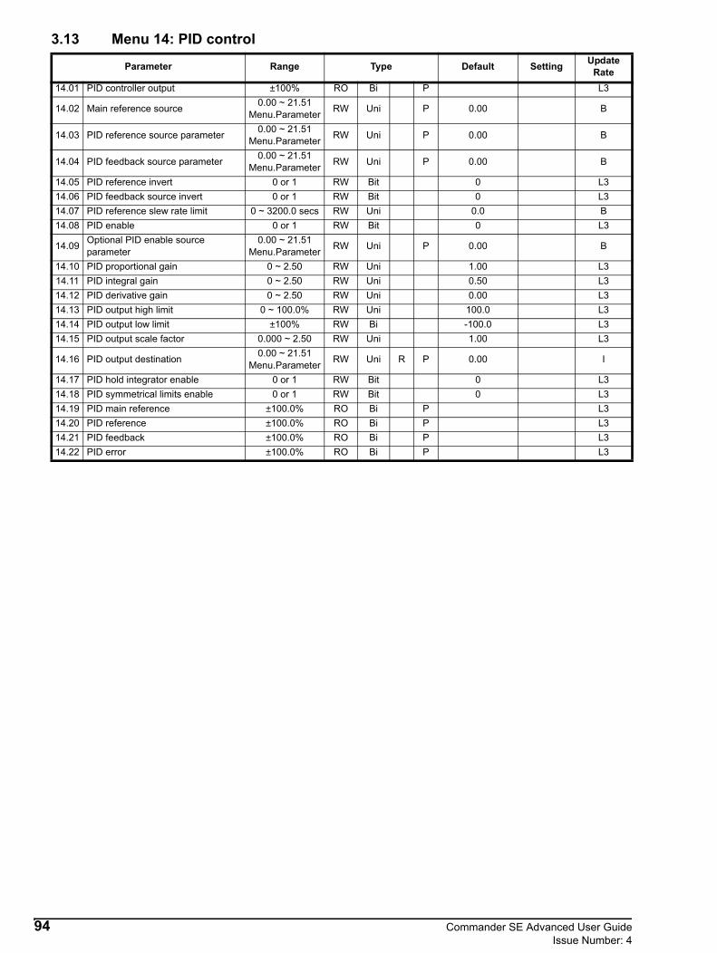
3.13 Menu 14: PID control
Parameter Range Type Default Setting Update Rate
14.01 PID controller output ±100% RO Bi P L3
14.02 Main reference source 0.00 ~ 21.51 Menu.Parameter RW Uni P 0.00 B
14.03 PID reference source parameter 0.00 ~ 21.51 Menu.Parameter RW Uni P 0.00 B
14.04 PID feedback source parameter 0.00 ~ 21.51 Menu.Parameter RW Uni P 0.00 B
14.05 PID reference invert 0 or 1 RW Bit 0 L314.06 PID feedback source invert 0 or 1 RW Bit 0 L314.07 PID reference slew rate limit 0 ~ 3200.0 secs RW Uni 0.0 B14.08 PID enable 0 or 1 RW Bit 0 L3
14.09 Optional PID enable source parameter
0.00 ~ 21.51 Menu.Parameter RW Uni P 0.00 B
14.10 PID proportional gain 0 ~ 2.50 RW Uni 1.00 L314.11 PID integral gain 0 ~ 2.50 RW Uni 0.50 L314.12 PID derivative gain 0 ~ 2.50 RW Uni 0.00 L314.13 PID output high limit 0 ~ 100.0% RW Uni 100.0 L314.14 PID output low limit ±100% RW Bi -100.0 L314.15 PID output scale factor 0.000 ~ 2.50 RW Uni 1.00 L3
14.16 PID output destination 0.00 ~ 21.51 Menu.Parameter RW Uni R P 0.00 I
14.17 PID hold integrator enable 0 or 1 RW Bit 0 L314.18 PID symmetrical limits enable 0 or 1 RW Bit 0 L314.19 PID main reference ±100.0% RO Bi P L314.20 PID reference ±100.0% RO Bi P L314.21 PID feedback ±100.0% RO Bi P L314.22 PID error ±100.0% RO Bi P L3
94 Commander SE Advanced User GuideIssue Number: 4
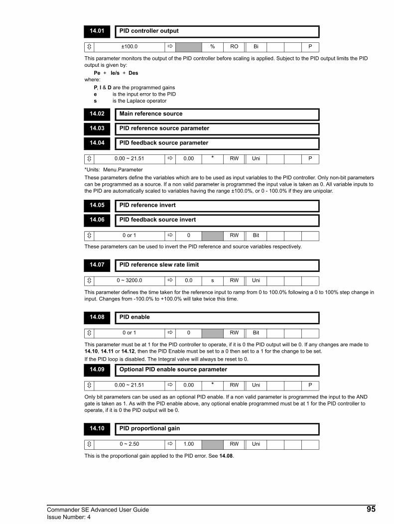
This parameter monitors the output of the PID controller before scaling is applied. Subject to the PID output limits the PID output is given by:
Pe + Ie/s + Deswhere:
P, I & D are the programmed gainse is the input error to the PIDs is the Laplace operator
*Units: Menu.ParameterThese parameters define the variables which are to be used as input variables to the PID controller. Only non-bit parameters can be programmed as a source. If a non valid parameter is programmed the input value is taken as 0. All variable inputs to the PID are automatically scaled to variables having the range ±100.0%, or 0 - 100.0% if they are unipolar.
These parameters can be used to invert the PID reference and source variables respectively.
This parameter defines the time taken for the reference input to ramp from 0 to 100.0% following a 0 to 100% step change in input. Changes from -100.0% to +100.0% will take twice this time.
This parameter must be at 1 for the PID controller to operate, if it is 0 the PID output will be 0. If any changes are made to 14.10, 14.11 or 14.12, then the PID Enable must be set to a 0 then set to a 1 for the change to be set.If the PID loop is disabled. The Integral valve will always be reset to 0.
Only bit parameters can be used as an optional PID enable. If a non valid parameter is programmed the input to the AND gate is taken as 1. As with the PID enable above, any optional enable programmed must be at 1 for the PID controller to operate, if it is 0 the PID output will be 0.
This is the proportional gain applied to the PID error. See 14.08.
14.01 PID controller output
±100.0 % RO Bi P
14.02 Main reference source
14.03 PID reference source parameter
14.04 PID feedback source parameter
0.00 ~ 21.51 0.00 * RW Uni P
14.05 PID reference invert
14.06 PID feedback source invert
0 or 1 0 RW Bit
14.07 PID reference slew rate limit
0 ~ 3200.0 0.0 s RW Uni
14.08 PID enable
0 or 1 0 RW Bit
14.09 Optional PID enable source parameter
0.00 ~ 21.51 0.00 * RW Uni P
14.10 PID proportional gain
0 ~ 2.50 1.00 RW Uni
Commander SE Advanced User Guide 95Issue Number: 4

This is the gain applied to the PID error before being integrated. See 14.08.
This is the gain applied to the PID error before being differentiated. See 14.08.
If parameter 14.18 is set to 0 this is the maximum positive PID output, and if 14.18 is set to 1 this is a symmetrical limit on the PID output.
The maximum negative or minimum positive PID output can be limited by this parameter if parameter 14.18 is set to 0. This parameter has no function if parameter 14.18 is set to 1.
The PID output is scaled by this parameter before being added to the main reference. After the addition to the main reference, the output is automatically scaled again to match the range of the destination parameter.
This destination parameter should be set up with the parameter that the PID controller is to control. Only non-bit parameters which are not protected can be controlled by the PID function. If a non valid parameter is programmed the output is not routed anywhere. If the PID is to control speed then it is suggested that one of the preset speed parameters is entered here.
When this parameter is set to 0, the integrator operates normally. Setting this parameter to 1 will cause the integrator value to be held as long as the PID is enabled when the drive is disabled. If the PID is disabled, the integral value will always be reset to 0.
When this parameter is set to 1, 14.13 is used as a symmetrical limit on the PID output, while if it is set to 0 the positive and negative limits can be set differently with parameters 4.13 and 4.14.
This parameter monitors the Main reference input of the PID controller.
14.11 PID integral gain
0 ~ 2.50 0.50 RW Uni
14.12 PID derivative gain
0 ~ 2.50 0.00 RW Uni
14.13 PID output high limit
0 ~ 100.0 100.0 % RW Uni
14.14 PID output low limit
±100.0 -100.0 % RW Bi
14.15 PID output scale factor
0.00 ~ 2.50 1.00 RW Uni
14.16 PID output destination
0.00 ~ 21.51 0.00 * RW Uni R P
14.17 PID hold integrator enable
0 or 1 0 RW Bit
14.18 PID symmetrical limits enable
0 or 1 0 RW Bit
14.19 PID main reference
±100.0 % RO Bi P
96 Commander SE Advanced User GuideIssue Number: 4

This parameter monitors the reference input of the PID controller.
This parameter monitors the feedback input of the PID controller.
This parameter monitors the error of the PID controller.
14.20 PID reference
±100.0 % RO Bi P
14.21 PID feedback
±100.0 % RO Bi P
14.22 PID error
±100.0 % RO Bi P
Commander SE Advanced User Guide 97Issue Number: 4

98 Commander SE Advanced User GuideIssue Number: 4
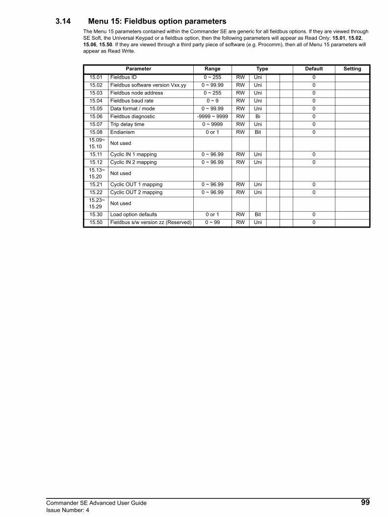
3.14 Menu 15: Fieldbus option parametersThe Menu 15 parameters contained within the Commander SE are generic for all fieldbus options. If they are viewed through SE Soft, the Universal Keypad or a fieldbus option, then the following parameters will appear as Read Only: 15.01, 15.02, 15.06, 15.50. If they are viewed through a third party piece of software (e.g. Procomm), then all of Menu 15 parameters will appear as Read Write.
Parameter Range Type Default Setting15.01 Fieldbus ID 0 ~ 255 RW Uni 015.02 Fieldbus software version Vxx.yy 0 ~ 99.99 RW Uni 015.03 Fieldbus node address 0 ~ 255 RW Uni 015.04 Fieldbus baud rate 0 ~ 9 RW Uni 015.05 Data format / mode 0 ~ 99.99 RW Uni 015.06 Fieldbus diagnostic -9999 ~ 9999 RW Bi 015.07 Trip delay time 0 ~ 9999 RW Uni 015.08 Endianism 0 or 1 RW Bit 015.09~ 15.10 Not used
15.11 Cyclic IN 1 mapping 0 ~ 96.99 RW Uni 0 15.12 Cyclic IN 2 mapping 0 ~ 96.99 RW Uni 0 15.13~ 15.20 Not used
15.21 Cyclic OUT 1 mapping 0 ~ 96.99 RW Uni 0 15.22 Cyclic OUT 2 mapping 0 ~ 96.99 RW Uni 0 15.23~ 15.29 Not used
15.30 Load option defaults 0 or 1 RW Bit 015.50 Fieldbus s/w version zz (Reserved) 0 ~ 99 RW Uni 0
Commander SE Advanced User Guide 99Issue Number: 4

The fieldbus option menu exists all the time within the drive. All the following Menu 15 parameters are stored in the drive EEPROM, except those indicated. A generic description is given here, see the appropriate fieldbus module manual for more details.
e.g. V03.02.01 = 3.02 (The ZZ component will be displayed in 15.50)
0 = Disabled
The selected baud rate depends upon the fieldbus module fitted. See relevant fieldbus for baud rate settings.
The selected data format / mode depends on the fieldbus module fitted.
See relevant fieldbus manual for data format / mode settings.
* Network Cycles per Second
15.01 Fieldbus ID
0 ~ 255 0 RW Uni
Fieldbus IDNot Fitted 0Profibus DP 1Interbus S 2CAN 5
15.02 Fieldbus software version Vxx.yy
0 ~ 99.99 RW Uni
0-9 0-9 0-9 0-9
X X • Y Y
15.03 Fieldbus node address
0 ~ 255 0 RW Uni
15.04 Fieldbus baud rate
0 ~ 9 0 RW Uni
15.05 Data format / mode
0 ~ 99.99 0 RW Uni
15.06 Fieldbus diagnostic
-9999 ~ 9999 * RW Bi
Value Description-2 Fieldbus initialisation failure.-1 Initialisation complete but no network running.0 Network running but no network cycles per second detected.x Network cycles per second detected.
NOTE
100 Commander SE Advanced User GuideIssue Number: 4

The delay time that is required for the loss of communications to cause a trip.0 = Disabled
1 = Little (LSB 1st)0 = Big (MSB 1st)
This parameter selects the order of bytes transmitted/received for cyclic data words.
* Parameter
e.g. 11.28 = 11.28 0 = Disabled
* Parameter
e.g. 11.28 = 11.28 0 = Disabled
Cleared once defaults are loaded.
Indicates the software sub version of the fieldbus module software.
15.07 Trip delay time
0 ~ 9999 0 ms RW Uni
15.08 Endianism
0 or 1 0 RW Bit
15.09~15.10 Unused parameters
15.11~15.12 Cyclic IN mappings
0 ~ 96.99 0 * RW Uni
0-9 0-9 0-9 0-9
X X • Y Y
15.13~15.20 Unused parameters
15.21~15.22 Cyclic OUT mappings
0 ~ 96.99 0 * RW Uni
0-9 0-9 0-9 0-9
X X • Y Y
15.23~15.29 Unused parameters
15.30 Load option defaults
0 or 1 0 RW Bit
15.31~15.49 Unused parameters
15.50 Software version zz (Reserved)
0 ~ 99 RO Uni
Commander SE Advanced User Guide 101Issue Number: 4
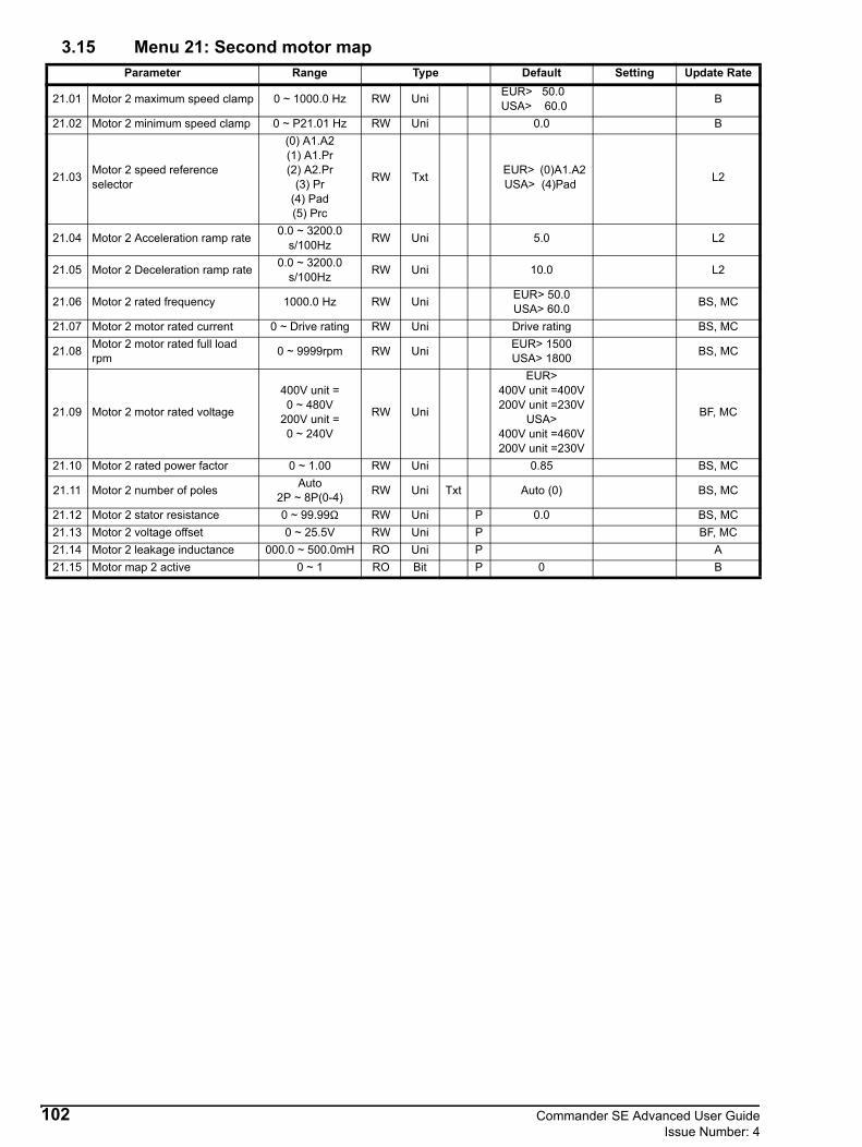
3.15 Menu 21: Second motor mapParameter Range Type Default Setting Update Rate
21.01 Motor 2 maximum speed clamp 0 ~ 1000.0 Hz RW Uni EUR> 50.0 USA> 60.0 B
21.02 Motor 2 minimum speed clamp 0 ~ P21.01 Hz RW Uni 0.0 B
21.03 Motor 2 speed reference selector
(0) A1.A2(1) A1.Pr(2) A2.Pr
(3) Pr(4) Pad(5) Prc
RW Txt EUR> (0)A1.A2 USA> (4)Pad L2
21.04 Motor 2 Acceleration ramp rate 0.0 ~ 3200.0 s/100Hz RW Uni 5.0 L2
21.05 Motor 2 Deceleration ramp rate 0.0 ~ 3200.0 s/100Hz RW Uni 10.0 L2
21.06 Motor 2 rated frequency 1000.0 Hz RW Uni EUR> 50.0USA> 60.0 BS, MC
21.07 Motor 2 motor rated current 0 ~ Drive rating RW Uni Drive rating BS, MC
21.08 Motor 2 motor rated full load rpm 0 ~ 9999rpm RW Uni EUR> 1500
USA> 1800 BS, MC
21.09 Motor 2 motor rated voltage
400V unit =0 ~ 480V
200V unit =0 ~ 240V
RW Uni
EUR> 400V unit =400V200V unit =230V
USA>400V unit =460V200V unit =230V
BF, MC
21.10 Motor 2 rated power factor 0 ~ 1.00 RW Uni 0.85 BS, MC
21.11 Motor 2 number of poles Auto2P ~ 8P(0-4) RW Uni Txt Auto (0) BS, MC
21.12 Motor 2 stator resistance 0 ~ 99.99Ω RW Uni P 0.0 BS, MC21.13 Motor 2 voltage offset 0 ~ 25.5V RW Uni P BF, MC21.14 Motor 2 leakage inductance 000.0 ~ 500.0mH RO Uni P A21.15 Motor map 2 active 0 ~ 1 RO Bit P 0 B
102 Commander SE Advanced User GuideIssue Number: 4

When the second motor map is implemented with parameter 11.45, the display will show the programmed second motor map values.There is a delay of approximately 1 second for the digital output to change state when changing from one motor map to the other.
This parameter is a symmetrical limit on both directions of rotation.This parameter defines the drive absolute maximum frequency reference, although slip compensation and current limit can increase the motor frequency further.
Used in unipolar mode to define the drive minimum speed. This can be overridden by maximum speed clamp 21.01. If adjusted less than 21.02, inactive during jogging.
This parameter is used to select a speed reference for motor 2 as follows:0 A1.A2 Analog voltage input on terminal 2 and analog current input on terminal 5 selected by terminal 12. Jog
selected by terminal 13.1 A1.Pr Analog voltage input on terminal 2 and three preset speeds selected by terminals 12 and 13.2 A2.Pr Analog current input on terminal 5 and three preset speeds selected by terminals 12 and 13.3 Pr 4 preset speeds selected by terminals 12 and 13.4 PAd Keypad Control.5 PrC Precision reference
Automatic set-upAs parameter 05 is changed from A1.A2 to A1.Pr etc. through the drives keypad, parameter 21.03 will change accordingly as per the above numerical value.Also the destination parameters of terminals 12 and 13 will change accordingly as long as 8.39 = 0 - automatic set-up is enabled.
PrC cannot be selected from parameter 05 through the drives keypad although it will be displayed if parameter 1.14 is set to 5.
Advanced set-upWhen 21.03 is set to 0, the reference selected can also depend on the state of bit parameters 1.41 to 1.44. These bits are controlled by digital inputs such that references can be selected by external control. If any of the bits are set, the appropriate reference is selected (indicated by 1.49). If more than 1 bit is set the highest number will have priority.
21.01 Motor 2 maximum speed clamp
0 ~ 1000.0 Europe> 50.0USA> 60.0 Hz RW Uni
21.02 Motor 2 minimum speed clamp
0 ~ 21.01 0.0 Hz RW Uni
21.03 Motor 2 speed reference selector
0 ~ 5EUR> 0
USA> 4RW Uni Txt
Parameter 05 Parameter 21.03 Terminal 12 destination
Terminal 13 destination Parameter 1.49
A1.A2 0 1.41 6.31 1A1.Pr 1 1.45 1.46 1A2.Pr 2 1.45 1.46 2
Pr 3 1.45 1.46 3PAd 4 4PrC 5 5
Parameter 1.41
Parameter 1.42
Parameter 1.44
Parameter 1.44
Frequency reference selected
Parameter 1.49
0 0 0 0 Analog reference 1 (A1) 11 0 0 0 Analog reference 2 (A2) 2x 1 0 0 Preset reference (Pr) 3x x 1 0 Keypad reference (PAd) 4x x x 1 Precision reference (Prc) 5
NOTE
Commander SE Advanced User Guide 103Issue Number: 4

In analog reference 1 and analog reference 2 modes, a preset speed will be selected instead of analog reference 1 or analog reference 2 if the preset speed selected is any other than preset speed 1 even if the preset reference, 1.42, is not selected. This is because of the easy set-up modes that give the user the flexibility to select between analog reference 1 and 3 preset speeds, or analog reference 2 and 3 presets speed with only 2 digital inputs.
The ramp rates are expressed as time for a change of 100Hz on the ramp output. Therefore with a programmed ramp time of 5 seconds the ramp output will reach 50Hz from 0 in 2.5 seconds.
The motor rated frequency is used to define the voltage to frequency characteristic applied to the drive (see 5.14 and 21.09).
The motor rated current should be set to the machine nameplate value for rated current.This value is used in the following:
Current limit, see parameter 4.07Ixt system, see parameter 4.15Slip compensation, see parameter 5.36Dynamic v to f control, see parameter 5.13
The rated full load rpm is used with the motor rated frequency and No. of poles to calculate the rated slip of the induction machine in Hz.
rated slip = motor rated frequency - (no. of pole pairs x motor full load rpm / 60) = 21.06 - ((21.11 / 2) x 21.08 / 60)
The rated slip is used to calculate the frequency adjustment required to compensate for slip from the following equation:slip compensation = rated slip x active current / rated active current
If slip compensation is required this parameter should be set to the name-plate value, which should give the correct rpm for a hot machine.Sometimes it will be necessary to adjust this when the drive is commissioned because the nameplate value might be inaccurate. Slip compensation will operate correctly for below base speed and field weakening operation. Slip compensation will not cause a frequency in the opposite direction to the post ramp frequency reference.
21.04 Motor 2 Acceleration ramp rate
21.05 Motor 2 Deceleration ramp rate
0.0 ~ 3200.0 s/100Hz RW Uni
Parameter Function Default 21.04 Motor 2 Accel 1 5.0 21.05 Motor 2 Decel 1 10.0
21.06 Motor 2 rated frequency
1000.0Europe> 50.0
USA> 60.0Hz RW Uni
21.07 Motor 2 motor rated current
0 ~ Drive rated current Drive rated current A RW Uni
21.08 Motor 2 motor rated full load rpm
0 ~ 9999 Europe> 1500 USA> 1800 rpm RW Uni
NOTE
104 Commander SE Advanced User GuideIssue Number: 4

This voltage is used in conjunction with the motor rated frequency (21.06) to define the voltage to frequency characteristic applied to the machine. If fixed boost is selected (5.14 = 2) the following characteristic is used.
If vector mode is selected (5.14 = 0 or 1) a linear characteristic is used from 0Hz to rated frequency, and then a constant voltage above rated frequency. When the drive operates between rated frequency/50 and rated frequency/4, full vector based stator resistance (Rs) compensation is applied. However there is a delay of 0.5s when the drive is enabled during which only partial vector based compensation is applied to allow the machine flux to build up. When the drive operates between rated frequency/4 and rated frequency/2 (this may change after some testing has been carried out) the Rs compensation is gradually reduced to zero as the frequency increases. For the vector modes to operate correctly the stator resistance (21.12), motor rated power factor (21.10) and voltage offset (21.13) are all required to be set up accurately.
The power factor is used in conjunction with the motor rated current (21.07) to calculate the rated active current. Enter this from the name plate of the motor. When a rotating autotune is carried out by the drive, the calculated power factor is automatically saved by the drive.
*Units: poles (by text), pole pairs (by number)When Auto is selected, the drive automatically calculates the number of motor poles of the machine from the settings in parameters 21.08 and 21.06. If either of these parameters are adjusted for a special motor or to modify the V/f characteristic, the automatic calculation may calculate the number of motor poles incorrectly. This would cause an incorrect slip compensation to be applied and the rpm speed indication would be incorrect. Therefore, the correct number of motor poles should be programmed manually.
21.09 Motor 2 motor rated voltage
EUR: 50Hz Defaults400V units > 0 ~ 480200V units> 0 ~ 240
400V units> 400200V units> 230 V RW Uni
USA: 60Hz Defaults 400V units > 0 ~ 480200V units > 0 ~ 240
400V units> 460200V units 230 V RW Uni
21.10 Motor 2 rated power factor
0 ~ 1.00 0.85 RW Uni
21.11 Motor 2 number of poles
Auto, 2P-8P (0-4) Auto (0) * RW Uni Txt
voltageboost
outputvoltage
21.09
21.09/2
21.06 / 2 21.06 outputfrequency
Output voltage characteristic
Commander SE Advanced User Guide 105Issue Number: 4

This parameter stores the stator resistance of the machine for vector mode operation. Although it is designated as read/write, it is read only if vector mode 0 is selected with parameter 5.14. If the drive cannot achieve the necessary current levels to measure the stator resistance in mode 0 or during an autotune (e.g. there is no motor connected to the drive), an rS trip will occur and the value in parameter 21.12 remains unchanged. If the necessary current level can be achieved, but the calculated resistance exceeds the maximum values for the particular drive size, an rS trip will occur and parameter 21.11 will contain the maximum allowed value. The maximum value can be calculated from the following formula:
Rsmax = VDC full_scale / (Ifull_scale * 2)
where: VDC full_scale = Maximum measurable DC Bus voltage (420V or 830V)Ifull_scale = Drive rated current √2 x 2.2
When an autotune is carried out by the drive, the calculated stator resistance is automatically saved.
The stator resistance test is carried out at half and full rated motor current. A current is applied in the y axis of the reference frame with zero frequency, and so DC current flows in all three phases of the machine. The results are as shown on the following diagram.
The gradient of the line gives the stator resistance, cabling resistance and resistance effects within the drive. The units are converted to ohms before being stored in 21.12. The drive must produce a voltage before any current flows, shown as Voffset. This includes IGBT voltage drops etc. To obtain good performance at low frequencies where the machine terminal voltage is small this offset must be taken into account. The value shown in 21.13 is given in volts, representing the voltage that would be applied on the U phase output as a DC level. The voltages on the other two phases would be -Voffset/2. It is not possible for the user to measure this voltage easily, and so an automatic measurement procedure should be used, either by using the autotune or selecting mode 0 (see 5.14).
The value of inductance stored in this parameter is the total leakage inductance (Ls') of the motor. The value can be measured at the start of the magnetising current test and stored in this parameter.The total leakage inductance can be calculated from the steady state per phase equivalent circuit of the motor:
Ls' = L1 + (L2.Lm / (L2 + Lm))
Ls' is used for automatic calculation of the motor power factor during the autotune test.
This parameter will change from a logic 0 to 1 when motor map 2 becomes active.The second motor map will become active when 11.45 is set to a 1 and the drive is in a disabled, tripped or standby mode. If the drive is running, 11.45 will be set to a 1 but the second motor map will not be implemented.This parameter can be programmed to a digital output to close a second motor contactor when motor map 2 becomes active.See Chapter 12 Applications for a second motor map set-up example.
21.12 Motor 2 stator resistance
0 to 99.99 0.0 Ω RW Uni P
21.13 Motor 2 voltage offset
0 ~ 25.5 V RW Uni
21.14 Motor 2 leakage inductance
000.0 ~ 500.0 mH RO Uni P
21.15 Motor map 2 active
0 ~ 1 0 RO Bit P
Voltage
V 2
V 1
Voffset
Irated/2 I rated
106 Commander SE Advanced User GuideIssue Number: 4

4 Drive Information4.1 Power Terminal Connections
Figure 4-1 Commander SE Size 1 power terminal connections
* See Fuses on page 24 of the Commander SE User Guide (Issue 8)
Figure 4-2 Commander SE Size 2 to 4 power terminal connections
When a Commander SE Size 2 200 volt unit is used on single phase, use terminals L1 and L2.
Figure 4-3 Commander SE Size 5 power terminal connections
L1 L2/N PE U V W
OptionalRFI filter
Optionalline reactor
MainsSupply
Fuses
L1 L2/NSupplyGround
Motor
MotorGround
Circuit breaker/Isolator
*
OptionalMotorGround
L1 L2
L2L1+ - L3 PEDBR U V W
Optional RFI filter
Optionalline reactor
Fuses
L3SupplyGround
MainsSupply
Motor
MotorGround
Start/Reset
Stop
Optional
Thermalprotection
device
BrakingResistor
OptionalMotorGround
NOTE
L1 L2
L2L1 + _L3 U V W
Optional RFI filter
Optionalline reactor
Fuses
L3MainsSupply
Motor
MotorGround
Start/Reset
Stop
Thermalprotection
device
BrakingResistor
SupplyGround
Optional
OptionalMotor
Ground
Commander SE Advanced User Guide 107Issue Number: 4

4.1.1 Power terminal torques
4.1.2 Thermal protection for an optional braking resistorFigure 4-2 and Figure 4-3 show a typical circuit arrangement for braking resistor protection. This thermal protection must disconnect the AC supply from the drive if the resistor becomes overloaded. (Do not use overload opening contact in line with braking resistor).
4.2 Commander SE power circuit layoutsFigure 4-4 Commander SE size 1 power circuit layout
Figure 4-5 Commander SE size 2, 3 and 4 power circuit layout
Commander SE sizes 2, 3 and 4 can be powered directly on to its + and - DC terminals from a DC power supply without any external softstart circuitry.Commander SE size 5 requires an external softstart circuit, see Figure 4-7.
Drive sizeMaximum power terminal
screw/stud torque
Nm lb in
1 & 2 1 9
3 & 4 2 18
Nm lb ft
5 15 11
WARNING
Motor
Motor
+DC bus
-DC bus
* Not on Commander SE size 2
*
108 Commander SE Advanced User GuideIssue Number: 4

Figure 4-6 Commander SE size 5 power circuit layout
Figure 4-7 Method of powering up the Commander SE size 5 by the DC bus using the drives internal inrush resistor
The source of the relay must NOT be changed from Drive Healthy. For relay ratings refer to the Commander SE User Guide.
4.3 Gland plate holesA slot has been provided in the gland plate of sizes 1 to 4 for control cables. One of the gland plate holes can be used for control cables but this should be separate from any power cables.Size 5 has a separate gland plate with two 22mm holes for the control cables.Table 4-1 Gland plate hole dimensions
Motor
+DC bus
-DC bus
L1 L2 L3 U V W + -
DC Supply with eachdrive individually fused
NC NO
Soft startcontactor
110V ac supply for softstart contactor coil
Contactor coil supplymust be wired throughthe drive healthy relay
Terminal 15
Terminal 16
Contactorcoil
DC Choke
NO
Normally Open Auxiliarycontact must be hardwired with the drive
enable on terminal 9
NOTE
Drive sizeNumber of holes in power terminal gland plate
22mm 27mm1 32 33 1 24 2 25 11
Commander SE Advanced User Guide 109Issue Number: 4

4.4 Control terminal connectionsThe terminal connections are shown in Figure 4-8. As default - in positive logic. Maximum control terminal screw torque: 0.6 Nm (5.5 lb in).Figure 4-8 Control terminal connections
The connection arrangement shown here illustrates how the terminals are intended to be used. Screening of the analog signal wires is not essential, but reduces the risk of electrical noise causing disturbance to the signals.Where full EMC precautions are required, the guidelines in section 4.5.2 of the Commander SE User Guide must also be followed to ensure compliance with radio frequency emission limits. This requires the use of one or more screened cables for all wiring to terminals 1 to 14, with the screen bonded to the gland plate (ground). This results in the 0V common terminal being connected to ground through the cable screen.Where it is required to keep 0V separate from ground, there are two possibilities:• Use a multi-core cable with overall screen, using one core for the 0V connection. There is a slight risk of
electrical noise affecting the analog inputs.• Use a double screened cable for the analog inputs, with the inner screen connected to 0V and the outer screen
to ground.
4.5 Serial communication connectionsSerial communication connections can be made via the RJ45 connector (see Figure 4-8).
PIN 2 RXTXPIN 3 0VPIN 4 +26V (+10% / -7%) 100mA serial communicationsPIN 6 TX EnablePIN 7 RX\TX\
When using a suitable serial communications converter with Commander SE, it is recommended that no terminating resistors be connected on the network. This applies to any of the drives on the network and also any converter used. It may be necessary to link out the terminating resistor within the converter, depending on which type is used. The information on how to link out the terminating resistor will normally be contained in the user information supplied with the converter. Terminating resistors are of little or no value when used on RS485 networks operating at or below 19.2KBaud.
The communications port of the Commander SE drive is double-insulated from the power electronics and single insulated from the status relay contacts. Providing that the voltage on the status relay contacts does not exceed 110V, the communications port meets the requirements for SELV in EN50178. However, in the event of a serious fault in the drive the safety barriers could be breached. Therefore when using the communications port with a personal computer or centralised controller e.g. PLC, an isolation device must be included with rated voltage at least equal to the drive supply voltage. Ensure that the correct fuses are installed at the drive input, and that the drive is connected to the correct supply voltage.
NOTE
WARNING
110 Commander SE Advanced User GuideIssue Number: 4

4.6 Control terminal specificationsThe control terminals of the Commander SE drive are double-insulated from the power electronics and single-insulated from the status relay contacts. Providing that the voltage on the status relay contacts does not exceed 110V, the control terminals meet the requirements for SELV in EN50178. However, in the event of a serious fault in the drive the safety barriers could be breached. The installer must ensure that the external control circuits are insulated from human contact by at least one layer of insulation rated for use at the AC supply voltage. If the control circuits are to be connected to other circuits classified as SELV e.g. a personal computer, an additional isolating barrier must be included in order to maintain SELV classification. Ensure that the correct fuses are installed at the drive input, and that the drive is connected to the correct supply voltage.
4.6.1 Default configurationAll outputs (+24, +10V, Digital output and Analog output) could be permanently damaged if a negative voltage greater than -1V is applied to them.
The remote current speed-reference input circuit incorporates a protection circuit to prevent any internal damage within the drive in the event of an external controller fault. This protection circuit senses the input current and if this exceeds 25mA, a FET disconnects the external controller from the drive. This FET will also disconnect the external controller signal when the drive is powered off.
WARNING
1 0V common
2 Local Speed reference input (A1)Type of input Single-endedVoltage range 0 to +10V
Scaling
0V represents the value in parameter 01, Minimum speed.+10V represents the value in parameter 02, Maximum speed.
Absolute maximum voltage range +35V to -18V with respect to 0V commonInput impedance 100kΩResolution 0.1% (10 bit)Accuracy ± 2%Sample time 6ms
3 +10V reference outputVoltage accuracy ± 2%Maximum output current 5mAProtection tolerates continuous short circuit to 0V
4 0V common
5 Remote current speed-reference input (A2)Default 4 - .20mA (See parameter 16)Type of input Single ended
Current range (programmable) 0-20mA, 20-0mA, 4-20mA, 20-4mA, 4-.20mA, 20-.4mA
Absolute maximum voltage range +30V to -18V with respect to 0V commonInput impedance 200ΩResolution 0.1% (10 bit)Accuracy ± 2%Sample time 6ms
CAUTION
Commander SE Advanced User Guide 111Issue Number: 4

The total current available from the +24V rail, which includes the digital output, is 100mA. Therefore if the digital output is providing 30mA, the +24V rail will only provide 70mA.
If the enable terminal is opened, the drive’s output is disabled and the motor will coast to a stop. The drive cannot be re-enabled for 2 seconds following the opening of the enable terminal.† Following a drive trip, open and close the Enable terminal to reset the drive. If the Run Forward or Run Reverse terminal is closed, the drive will run straight away.* Following a drive trip and a reset via the Stop/Reset key the Run Forward or Run Reverse terminals will need to be opened and closed to allow the drive to run. This ensures that the drive does not start when the Stop/Reset key is pressed.
There is a delay of 65ms in the drives software when switching from Run Forward to Run Reverse or vice-versa. The delay is to allow the direction of motor rotation to be changed without the drive entering the selected stopping mode, e.g. coast to stop.If the Commander SE is being used on an application where the terminal timing is critical, the terminal set-up mode should be changed as to remove this 65ms delay. This can be done by setting Parameter 35 to mode 2 or 3 so that the terminals are set up as Run/Stop terminals and not Run Forward/Run Reverse terminals.
6 Analog voltage outputDefault Motor Speed (See parameter 36)Absolute maximum voltage range +35V to -1V with respect to 0V commonVoltage range 0 to +10VScaling: Motor speed output 0V represent 0Hz/0 rpm output
+10V represents the value of parameter 02, Maximum speed.
% Motor load output
Maximum output current 5mAResolution 0.1% (10 bit)Accuracy ± 5%Update time 22msProtection tolerates continuous short circuit to 0V
7 +24V outputVoltage accuracy ± 10%Maximum output current 100mAProtection tolerates continuous short circuit to 0V
8 Digital outputFunction Zero Speed OutputAbsolute maximum voltage range +35V to -1V with respect to 0V commonVoltage range 0V to +24VMaximum output current 50mA at +24VOutput impedance 10kΩ pull-down resistor in inactive state. Update time 1.5msOperation of digital output +24V = Zero speed, 0V = Above zero speed
910111213
Digital input - Enable / Reset †Digital input - Run Forward (Edge triggered) *Digital input - Run Reverse (Edge triggered) *Digital input - Local/Remote Speed Ref (A1/A2)Digital input - Jog
Default Positive logic (See parameter 34)Voltage range 0V to +24VAbsolute maximum voltage range +35V to -18V with respect to 0V commonNominal threshold voltage +10VInput impedance 7.5kΩSample time 1.5ms
VOUTActive Current
1.5 Drive Rated Current×------------------------------------------------------------------------------------ 10×=
NOTE
NOTE
112 Commander SE Advanced User GuideIssue Number: 4

Provide fuse or other over-current protection in status relay circuit.
4.6.2 Digital inputs sample timesThe digital I/O sample times for the control terminals are shown in Default configuration on page 111. These times are correct but are the times for the control microprocessor to sample the digital inputs. The actual time for the drive to act upon these signals will be slightly longer.The digital input will be sampled within 1.5ms, then it takes between 4.5 to 6ms for this information to be passed across the serial communications link between the control microprocessor and the machine control DSP (Digital Signal Processor). The DSP runs on a 6kHz cycle and the information is processed as soon as it receives the information from the serial comms link.Example:The maximum time taken to disable the drive:
Control microprocessor update rate: 1.5ms maximumTime across serial comms link and DSP to process information: 6.0ms maximum
Therefore it will take a maximum of 7.5ms for the drive to disable from receiving the disable signal.
4.6.3 Digital output update rateThe time taken for the digital output to be updated will depend upon the parameter programmed to the digital output source (parameter 8.21). The DSP is run on a 6kHz cycle and the information is passed across the serial comms link on this cycle time.Example:The maximum update time for the drive healthy relay to be set:
DSP to process information and time across the serial comms link: 6.0ms maximumControl microprocessor update rate: 1.5ms maximum
Therefore it will take a maximum of 7.5ms for the drive healthy relay to be set to indicate a fault.Task Routine Levels:
The timing of each parameter can be seen in the single line parameter description at the beginning of each menu.
14 +24V outputVoltage accuracy ± 10%Maximum output current 100mAProtection tolerates continuous short circuit to 0V
1516
Status relay (Normally open)
Function Drive HealthyVoltage rating 240VAC /30VDCCurrent rating 2A/6A (resistive)
Contact isolation 2.5kVAC (meets IEC664-1 with over voltage category II)
Update time 6ms
Operation of contact
OPEN - AC supply removed from drive- AC supply applied to drive with the drive in a tripped conditionCLOSED- AC supply applied to drive with the drive in a ‘ready to run’ or ‘running’ condition (not tripped)
WARNING
Level Abbreviation TimeLevel 1 L1 1.5msLevel 2 L2 6.0msLevel 3 L3 22msBackground BBackground slow and motor changed BS, MCBackground fast and motor changed BF, MCBackground fast BFBackground fast and L1 BF, L1Background and Reset BF, IReset IMotor changed MCReset and Level 1 I, L1Autotune A
Commander SE Advanced User Guide 113Issue Number: 4
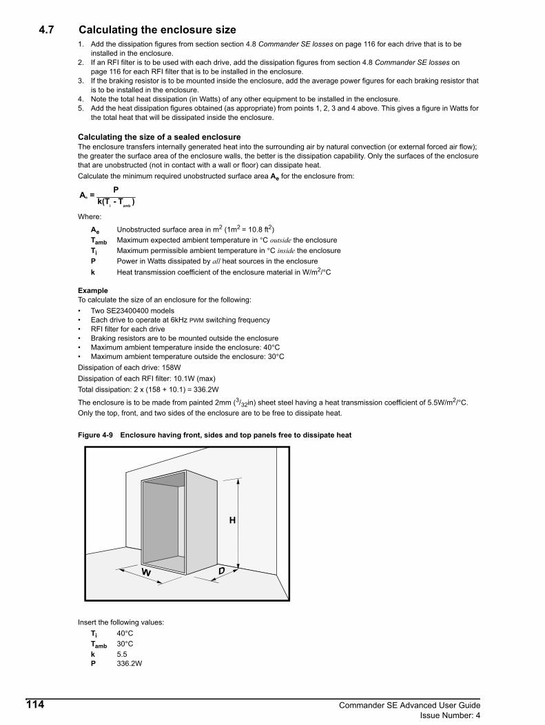
4.7 Calculating the enclosure size1. Add the dissipation figures from section section 4.8 Commander SE losses on page 116 for each drive that is to be
installed in the enclosure. 2. If an RFI filter is to be used with each drive, add the dissipation figures from section 4.8 Commander SE losses on
page 116 for each RFI filter that is to be installed in the enclosure.3. If the braking resistor is to be mounted inside the enclosure, add the average power figures for each braking resistor that
is to be installed in the enclosure. 4. Note the total heat dissipation (in Watts) of any other equipment to be installed in the enclosure.5. Add the heat dissipation figures obtained (as appropriate) from points 1, 2, 3 and 4 above. This gives a figure in Watts for
the total heat that will be dissipated inside the enclosure.
Calculating the size of a sealed enclosureThe enclosure transfers internally generated heat into the surrounding air by natural convection (or external forced air flow); the greater the surface area of the enclosure walls, the better is the dissipation capability. Only the surfaces of the enclosure that are unobstructed (not in contact with a wall or floor) can dissipate heat.Calculate the minimum required unobstructed surface area Ae for the enclosure from:
Where:
Ae Unobstructed surface area in m2 (1m2 = 10.8 ft2)Tamb Maximum expected ambient temperature in °C outside the enclosureTi Maximum permissible ambient temperature in °C inside the enclosureP Power in Watts dissipated by all heat sources in the enclosurek Heat transmission coefficient of the enclosure material in W/m2/°C
ExampleTo calculate the size of an enclosure for the following:• Two SE23400400 models• Each drive to operate at 6kHz PWM switching frequency• RFI filter for each drive• Braking resistors are to be mounted outside the enclosure• Maximum ambient temperature inside the enclosure: 40°C• Maximum ambient temperature outside the enclosure: 30°CDissipation of each drive: 158W Dissipation of each RFI filter: 10.1W (max) Total dissipation: 2 x (158 + 10.1) = 336.2W
The enclosure is to be made from painted 2mm (3/32in) sheet steel having a heat transmission coefficient of 5.5W/m2/°C. Only the top, front, and two sides of the enclosure are to be free to dissipate heat.
Figure 4-9 Enclosure having front, sides and top panels free to dissipate heat
Insert the following values:Ti 40°CTamb 30°Ck 5.5P 336.2W
A = Pk(T - T )e
i amb
114 Commander SE Advanced User GuideIssue Number: 4

The minimum required heat conducting area is then:
(1m = 3.3 ft)Estimate two of the enclosure dimensions — the height (H) and depth (D), for instance. Calculate the width (W) from:
Inserting H = 2m and D = 0.6m, obtain the minimum width:
If the enclosure is too large for the space available, it can be made smaller only by attending to one or all of the following:• Using a lower PWM switching frequency to reduce the dissipation in the drives • Reducing the ambient temperature outside the enclosure, and/or applying forced-air cooling to the outside of the
enclosure• Reducing the number of drives in the enclosure• Removing other heat-generating equipment
Calculating the air-flow in a ventilated enclosureThe dimensions of the enclosure are required only for accommodating the equipment. The equipment is cooled by the forced air flow.Calculate the minimum required volume of ventilating air from:
Where:
V Air-flow in m3 per hourTamb Maximum ambient temperature in °C outside the enclosureTi Maximum ambient temperature in °C inside the enclosureP Power in Watts dissipated by all heat sources in the enclosure
k Ratio of
Where:P0 is the air pressure at sea levelPI is the air pressure at the installationTypically use a factor of 1.2 to 1.3, to allow also for pressure-drops in dirty air-filters.
ExampleTo calculate the air flow for the following:• Two SE23400400 models• Each drive to operate at 6kHz PWM switching frequency• RFI filter for each drive• Braking resistors are to be mounted outside the enclosure• Maximum ambient temperature inside the enclosure: 40°C• Maximum ambient temperature outside the enclosure: 30°CDissipation of each drive: 158WDissipation of each RFI filter: 10.1W Total dissipation: 2 x (158 + 10.1) = 336.2WInsert the following values:
Ti 40°CTamb 30°Ck 1.3P 2190W
Then:
(1m3\hr = 0.59ft3\min)
Ae336.2
5.5 40 30–( )--------------------------------- 6.11m2 66.6ft2( )= =
WAe 2HD–
H D+--------------------------=
W 7.8 2 2× 0.6×( )–2 0.6+
---------------------------------------------- 2.1m 6ft10in( )= =
V 3kPTi Tamb–-------------------------=
P0PI------
V 3 1.3× 336.2×40 30–
--------------------------------------- 131m3\hr 504ft3\min( )= =
Commander SE Advanced User Guide 115Issue Number: 4
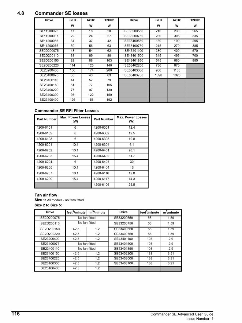
4.8 Commander SE losses
Commander SE RFI Filter Losses
Fan air flow Size 1: All models - no fans fitted.Size 2 to Size 5:
Drive 3kHz 6kHz 12kHz Drive 3kHz 6kHz 12kHz
W W W W W WSE11200025 17 18 20 SE33200550 210 230 265SE11200037 22 24 27 SE33200750 280 305 335SE11200055 34 37 42 SE33400550 130 190 295SE11200075 50 56 63 SE33400750 215 270 385SE2D200075 48 54 62 SE43401100 280 400 570SE2D200110 63 69 80 SE43401500 345 495 700SE2D200150 82 88 103 SE43401850 545 660 885SE2D200220 114 125 146 SE53402200 730 870SE23200400 156 174 206 SE53403000 950 1130SE23400075 35 43 63 SE53403700 1090 1325SE23400110 44 57 79SE23400150 61 77 105SE23400220 77 97 130SE23400300 95 122 159SE23400400 126 158 192
Part Number Max. Power Losses(W) Part Number Max. Power Losses
(W)
4200-6101 6 4200-6301 12.4
4200-6102 6 4200-6302 19.5
4200-6103 6 4200-6303 10.8
4200-6201 10.1 4200-6304 6.1
4200-6202 10.1 4200-6401 26.1
4200-6203 15.4 4200-6402 11.7
4200-6204 6 4200-6403 30
4200-6205 10.1 4200-6404 16
4200-6207 10.1 4200-6116 12.8
4200-6209 15.4 4200-6117 14.3
4200-6106 25.5
Drive feet3/minute m3/minute Drive feet3/minute m3/minuteSE2D200075 No fan fitted SE33200550 56 1.59
SE2D200110 No fan fitted SE33200750 56 1.59
SE2D200150 42.5 1.2 SE33400550 56 1.59SE2D200220 42.5 1.2 SE33400750 56 1.59SE23200400 42.5 1.2 SE43401100 103 2.9SE23400075 No fan fitted SE43401500 103 2.9SE23400110 No fan fitted SE43401850 103 2.9SE23400150 42.5 1.2 SE53402200 138 3.91SE23400220 42.5 1.2 SE53403000 138 3.91SE23400300 42.5 1.2 SE53403700 138 3.91SE23400400 42.5 1.2
116 Commander SE Advanced User GuideIssue Number: 4

4.9 Derating Curves4.9.1 Commander SE Size 1
There is no derating on 0.25kW and 0.37kW drives.
0.55kW
0.75kW
NOTE
10 20 30 40 50 60
1
2
33
4
Ambient Co
FLC (A)
3 + 6kHz
12kHz
10 20 30 40 50 60
1
2
33
4
Ambient Co
FLC (A)
4.5
12kHz
6kHz
3kHz
Commander SE Advanced User Guide 117Issue Number: 4

4.9.2 Commander SE Size 2200V 0.75kW (1 & 3 phase)
200V 1.1kW (1 & 3 phase)
10 20 30 40 50 60
1
2
33
4
Ambient Co
FLC (A)
12kHz
3 + 6kHz
10 20 30 40 50 60
1
2
33
4
Ambient Co
FLC (A)
12kHz
6kHz5
6
3kHz
118 Commander SE Advanced User GuideIssue Number: 4
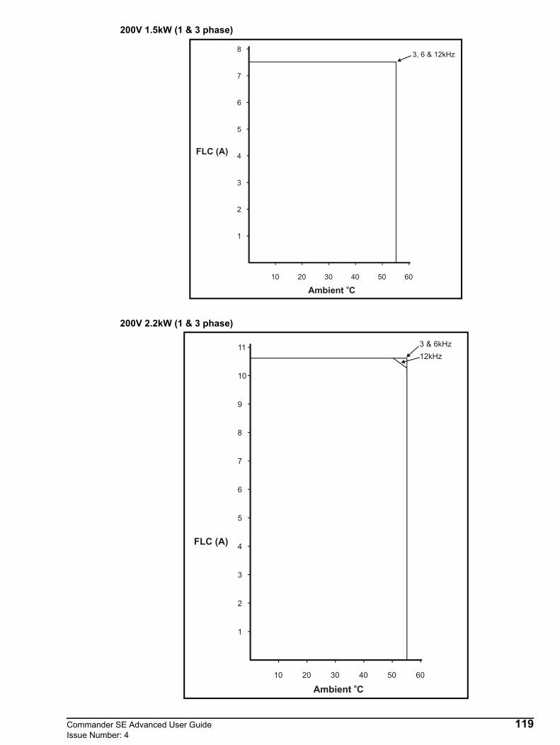
200V 1.5kW (1 & 3 phase)
200V 2.2kW (1 & 3 phase)
10 20 30 40 50 60
1
2
3
4
Ambient Co
FLC (A)
5
6
3, 6 & 12kHz
7
8
10 20 30 40 50 60
1
2
3
4
Ambient Co
FLC (A)
5
6
3 & 6kHz
7
8
9
10
1112kHz
Commander SE Advanced User Guide 119Issue Number: 4

200V 4kW (3 phase)
400V 0.75kW (3 phase)
10 20 30 40 50 60
2
4
8
6
16
Ambient Co
FLC (A)
3kHz
12kHz10
12
14
18
6kHz
10 20 30 40 50 60
1
2
33
Ambient Co
FLC (A)3kHz12kHz
0.5
1.5
2.5
6kHz
Typical no loadcurrent of 0.75kW motor
120 Commander SE Advanced User GuideIssue Number: 4
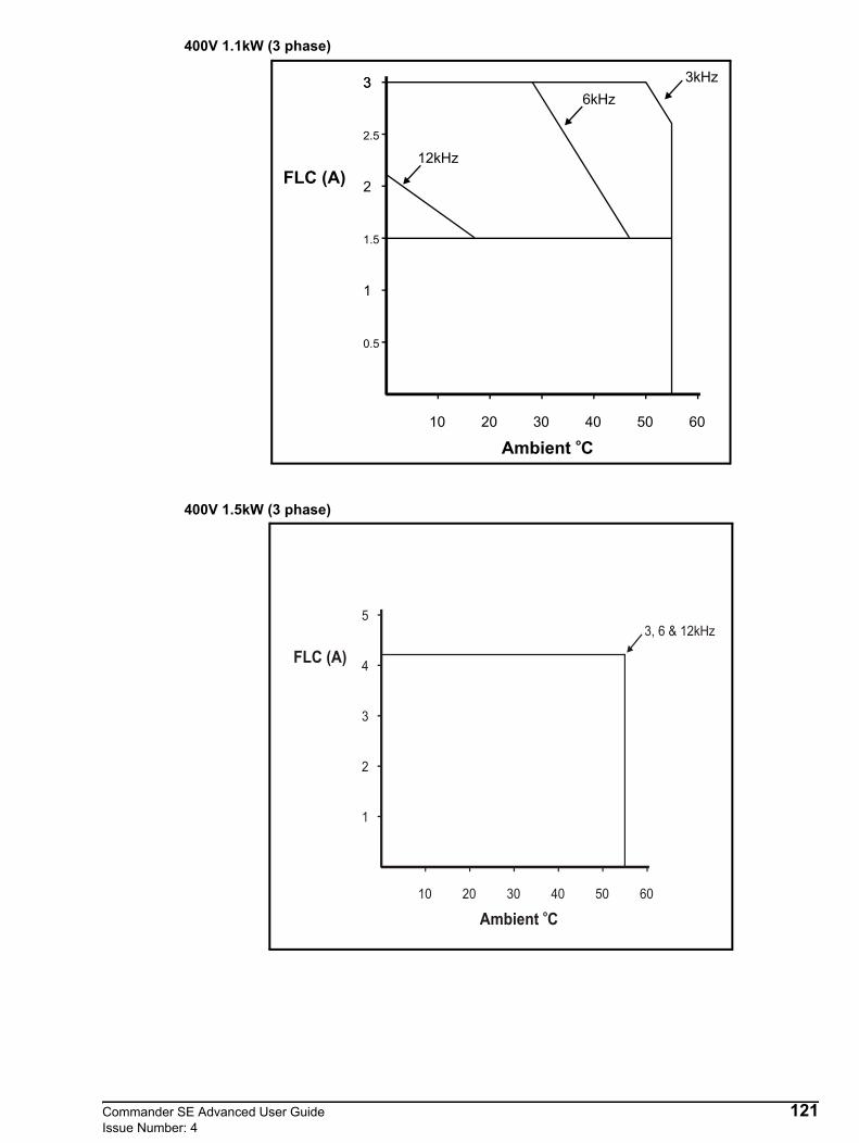
400V 1.1kW (3 phase)
400V 1.5kW (3 phase)
10 20 30 40 50 60
1
2
33
Ambient Co
FLC (A)
3kHz
12kHz
0.5
1.5
2.5
6kHz
10 20 30 40 50 60
2
4
Ambient Co
FLC (A)3, 6 & 12kHz
1
3
5
Commander SE Advanced User Guide 121Issue Number: 4

400V 2.2kW (3 phase)
400V 3kW (3 phase)
10 20 30 40 50 60
2
4
Ambient Co
FLC (A)
3 & 6kHz
1
3
5
6
12kHz
10 20 30 40 50 60
2
4
Ambient Co
FLC (A)
3 & 6kHz
1
3
5
6
12kHz
7
8
122 Commander SE Advanced User GuideIssue Number: 4

400V 4kW (3 phase)
10 20 30 40 50 60
2
4
Ambient Co
FLC (A)
3kHz
1
3
5
6
12kHz
7
8
9
10
6kHz
Commander SE Advanced User Guide 123Issue Number: 4

4.9.3 Commander SE Size 3 200V 5.5kW
200V 7.5kW
10 20 30 40 50 60
Ambient Co
FLC (A)
3kHz
12kHz
6kHz
10
30
25
20
15
5
10 20 30 40 50 60
Ambient Co
FLC (A)
3kHz
12kHz6kHz
10
30
25
20
15
5
124 Commander SE Advanced User GuideIssue Number: 4

400V 5.5kW
400V 7.5kW
10 20 30 40 50 60
2
4
8
6
Ambient Co
FLC (A)
3 & 6kHz
12kHz10
12
14
10 20 30 40 50 60
2
4
8
6
16
Ambient Co
FLC (A)
3kHz
12kHz10
12
14
18
6kHz
Commander SE Advanced User Guide 125Issue Number: 4

4.9.4 Commander SE Size 411kW
15kW
10 20 30 40 50 60
5
Ambient Co
FLC (A) 6kHz
12kHz
10
15
20
25
3kHz
10 20 30 40 50 60
5
Ambient Co
FLC (A)
6kHz
12kHz
10
15
20
25
30
35
3kHz
126 Commander SE Advanced User GuideIssue Number: 4

18.5kW
4.9.5 Commander SE Size 522kW
10 20 30 40 50 60
5
Ambient Co
FLC (A)
6kHz
12kHz10
15
20
25
30
35
3kHz
40
10 20 30 40 50
10
Ambient Co
FLC (A)
6kHz
20
30
40
503kHz
Commander SE Advanced User Guide 127Issue Number: 4

30kW
37kW
10 20 30 40 50
10
Ambient Co
FLC (A)
6kHz
20
30
40
503kHz
60
10 20 30 40 50
10
Ambient Co
FLC (A)
6kHz
20
30
40
50
3kHz60
70
128 Commander SE Advanced User GuideIssue Number: 4
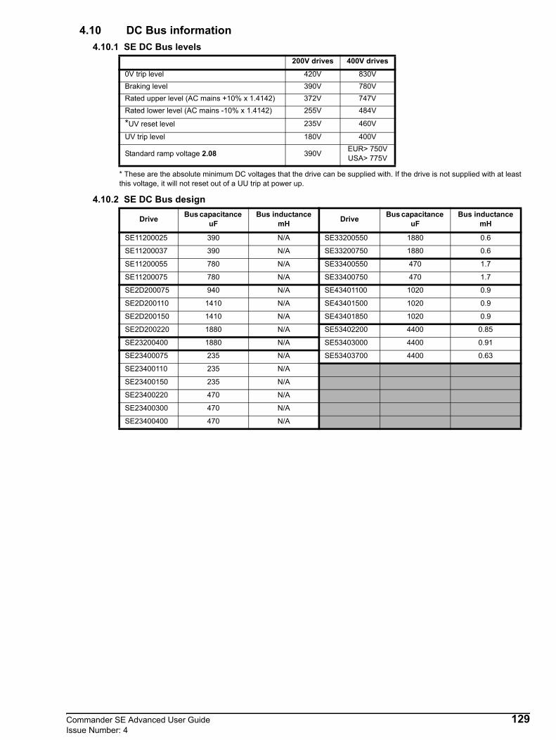
4.10 DC Bus information4.10.1 SE DC Bus levels
* These are the absolute minimum DC voltages that the drive can be supplied with. If the drive is not supplied with at least this voltage, it will not reset out of a UU trip at power up.
4.10.2 SE DC Bus design
200V drives 400V drives
0V trip level 420V 830VBraking level 390V 780VRated upper level (AC mains +10% x 1.4142) 372V 747VRated lower level (AC mains -10% x 1.4142) 255V 484V
*UV reset level 235V 460V
UV trip level 180V 400V
Standard ramp voltage 2.08 390V EUR> 750VUSA> 775V
Drive Bus capacitance uF
Bus inductance mH Drive Bus capacitance
uFBus inductance
mH
SE11200025 390 N/A SE33200550 1880 0.6
SE11200037 390 N/A SE33200750 1880 0.6
SE11200055 780 N/A SE33400550 470 1.7
SE11200075 780 N/A SE33400750 470 1.7
SE2D200075 940 N/A SE43401100 1020 0.9
SE2D200110 1410 N/A SE43401500 1020 0.9
SE2D200150 1410 N/A SE43401850 1020 0.9
SE2D200220 1880 N/A SE53402200 4400 0.85
SE23200400 1880 N/A SE53403000 4400 0.91
SE23400075 235 N/A SE53403700 4400 0.63
SE23400110 235 N/A
SE23400150 235 N/A
SE23400220 470 N/A
SE23400300 470 N/A
SE23400400 470 N/A
Commander SE Advanced User Guide 129Issue Number: 4

4.10.3 SE Inrush resistor
*Commander SE size 5 uses a resistor as its inrush current limiting resistor. Its value remains constant as the temperature increases.
The Commander SE sizes 1 to 4 use surge guards as its inrush current limiting resistors. The ohmic values are given at 25oC. This ohmic value reduces as the surge guards temperature increases.
4.11 High-capacitance cablesMost cables have an insulating jacket between the cores and armour or shield; these cables have low capacitance and are recommended. Cables that do not have an insulating jacket tend to have high capacitance; if a cable of this type is used, the maximum cable length is half that quoted in the table. The drawing below shows how to identify the two types.Figure 4-10 Cable construction influencing the capacitance.
Maximum motor cable lengthsThe capacitive loading of the drive by the motor cable means that the cable length limits shown in the table must be observed. Failure to do so can result in spurious OI.AC tripping of the drive. If longer cable lengths are required, consult your local Drive Centre or distributor.The capacitance of the cable used for the maximum cable lengths and EMC testing on Commander SE was measured at 412pF/m when using method 1 and 130F/m when using method 2, as below.Method 1By connecting the 3 phases together as one node and connecting the screen and earth (if any) as the other node and measuring the capacitance between these two points.
DriveInrush resistor
Ω at 25oCDrive
Inrush resistor Ω at 25oC
SE11200025 10 SE33200550 30
SE11200037 10 SE33200750 30
SE11200055 10 SE33400550 30
SE11200075 10 SE33400750 30
SE2D200075 20 SE43401100 30
SE2D200110 20 SE43401500 30
SE2D200150 20 SE43401850 30
SE2D200220 30 SE53402200 22*
SE23200400 30 SE53403000 22*
SE23400075 20 SE53403700 22*
SE23400110 20
SE23400150 20
SE23400220 20
SE23400300 30
SE23400400 30
NOTE
Normal capacitanceShield or armour separated from the cores
High capacitanceShield or armour close to the cores
412pF
130 Commander SE Advanced User GuideIssue Number: 4

Method 2By taking one phase as one node and the screen and earth (if any) as the other node and measuring the capacitance between these two points.
The same cable as used before would give a capacitance measurement of 130pF/m when using this method.
*This cable length is for 3kHz switching frequency. The cable length reduces in proportion to switching frequency; e.g. at 6kHz by a factor of 2 to 60m.
4.12 Storage and transportation4.12.1 Storage
The drive can be safely stored in its “as delivered” state for up to 2 years provided the drive environment is within the limits specified in the General Data section of the Commander SE User Guide. Following a 2 year storage period the DC Bus electrolytic capacitors will need reforming. This is a simple operation requiring a variable AC source (such as a Variac - single and three phase). Provided the DC electrolytic capacitors are reformed at the end of each and every 2 year storage period, the drive can be stored indefinitely.The reforming process is carried out as follows:• Connect the drive as illustrated (single phase Variac and drive shown). No other control/power connections are
necessary.• Suitably fuse the input to the Variac using slow-blow type fuses (e.g. 0.5A or similar) and a similar rated fuse to the input
of the drive.• With the Variac set to 0VAC output, turn on the supply and gradually increase the voltage to the drive (e.g. 4.5VAC per
minute with a maximum of 5VAC steps). Over a period of time increase the voltage from 0VAC to 275VAC (525VAC - 400V product). At the end of the time period, with 275VAC (525VAC - 400V product), applied remove the drive from the supply.
The reforming process is now complete and the drive can be stored for another 2 years.
Drive SizeMaximum motor cable length
m ft
1 75 246
2 100 330
3 150 495
4 150 495
5 120* 394*
130pF
V~
VariacDrive
Supply 200~240VAC 50/60Hz
L2
L1
Commander SE Advanced User Guide 131Issue Number: 4
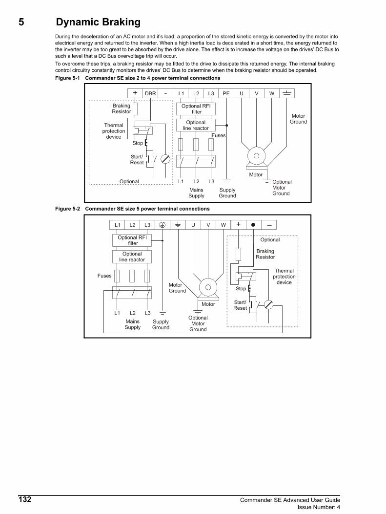
5 Dynamic BrakingDuring the deceleration of an AC motor and it’s load, a proportion of the stored kinetic energy is converted by the motor into electrical energy and returned to the inverter. When a high inertia load is decelerated in a short time, the energy returned to the inverter may be too great to be absorbed by the drive alone. The effect is to increase the voltage on the drives’ DC Bus to such a level that a DC Bus overvoltage trip will occur.To overcome these trips, a braking resistor may be fitted to the drive to dissipate this returned energy. The internal braking control circuitry constantly monitors the drives’ DC Bus to determine when the braking resistor should be operated.Figure 5-1 Commander SE size 2 to 4 power terminal connections
Figure 5-2 Commander SE size 5 power terminal connections
L1 L2
L2L1+ - L3 PEDBR U V W
Optional RFI filter
Optionalline reactor
Fuses
L3SupplyGround
MainsSupply
Motor
MotorGround
Start/Reset
Stop
Optional
Thermalprotection
device
BrakingResistor
OptionalMotorGround
L1 L2
L2L1 + _L3 U V W
Optional RFI filter
Optionalline reactor
Fuses
L3MainsSupply
Motor
MotorGround
Start/Reset
Stop
Thermalprotection
device
BrakingResistor
SupplyGround
Optional
OptionalMotor
Ground
132 Commander SE Advanced User GuideIssue Number: 4
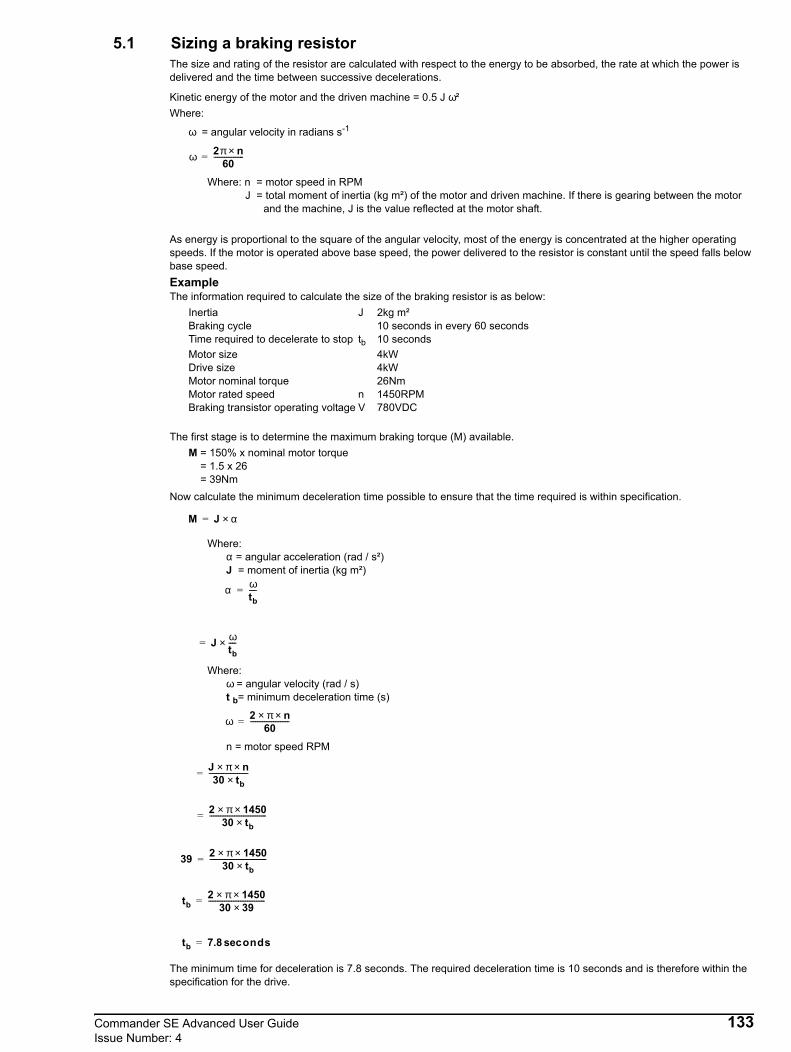
5.1 Sizing a braking resistorThe size and rating of the resistor are calculated with respect to the energy to be absorbed, the rate at which the power is delivered and the time between successive decelerations.
Kinetic energy of the motor and the driven machine = 0.5 J ω²Where:
ω = angular velocity in radians s-1
Where: n = motor speed in RPMJ = total moment of inertia (kg m²) of the motor and driven machine. If there is gearing between the motor
and the machine, J is the value reflected at the motor shaft.
As energy is proportional to the square of the angular velocity, most of the energy is concentrated at the higher operating speeds. If the motor is operated above base speed, the power delivered to the resistor is constant until the speed falls below base speed.ExampleThe information required to calculate the size of the braking resistor is as below:
Inertia J 2kg m²Braking cycle 10 seconds in every 60 secondsTime required to decelerate to stop tb 10 secondsMotor size 4kWDrive size 4kWMotor nominal torque 26NmMotor rated speed n 1450RPMBraking transistor operating voltage V 780VDC
The first stage is to determine the maximum braking torque (M) available.M = 150% x nominal motor torque = 1.5 x 26 = 39Nm
Now calculate the minimum deceleration time possible to ensure that the time required is within specification.
Where:α = angular acceleration (rad / s²)J = moment of inertia (kg m²)
Where: ω = angular velocity (rad / s)
t b= minimum deceleration time (s)
n = motor speed RPM
The minimum time for deceleration is 7.8 seconds. The required deceleration time is 10 seconds and is therefore within the specification for the drive.
ω 2π n×60
-----------------=
M J α×=
α ωtb----=
J ωtb----×=
ω 2 π× n×60
----------------------=
J π× n×30 tb×
----------------------=
2 π× 1450×30 tb×
--------------------------------=
39 2 π× 1450×30 tb×
--------------------------------=
tb2 π× 1450×
30 39×--------------------------------=
tb 7.8 ondssec=
Commander SE Advanced User Guide 133Issue Number: 4

Now using the required deceleration time of 10 seconds, calculate the required braking torque:
Now calculate the braking power:
Since braking occurs intermittently, the resistor can be rated for intermittent rather than continuous power dissipation so that the overload factor of the resistor can be used. This factor can be obtained from the cooling curves for resistor type that is being used. See the following example:
Figure 5-3 Examples cooling curves for power resistors (in practice, refer to the cooling curves for the resistor to be used)
The cooling curve indicates that for a braking time of 10 seconds and a repeat cycle time of 60 seconds, the overall factor (F) is 2.0.Calculate the required power rating of the resistor:
Now calculate the value of the braking resistor:
For this example use 120Ω which is the nearest value in the E12 range of resistors.In practice, use a resistor having a preferred value close to and lower than the calculated value. This is because the calculated value would cause the braking transistor to be switched on almost continuously during braking. In this case, the drive will not have full control of the DC Bus voltage. A lower value of braking resistor will cause the braking transistor to act as a chopper which will then allow the drive to control the DC Bus voltage more accurately.This reduction in value does not increase the power dissipation since the average voltage across the resistor is reduced by the braking transistor operating as a chopper.
Mb2 π× 1450×
30 10×--------------------------------=
Mb 30.4Nm=
PbMb π× n×
30 103×---------------------------=
30.4 π× 1450×30 103×
----------------------------------------=
4.6kW=
PRPbF
------ 4.6 103×2.0
------------------------ 2.3kW= = =
RmaxVR( )2
Pb---------------- 7802
4.6 103×------------------------ 132Ω= = =
134 Commander SE Advanced User GuideIssue Number: 4

Sizing an appropriate thermal overload relayCalculate the maximum permissible continuous current through the braking resistor as follows:
Where:PR is the power rating of the resistor to be used.R is the actual value of the braking resistor (not the calculated).
Use the tripping curves for the chosen manufacturer of thermal overload relay in order to find the overload factor (F) that will cause the relay to trip after 10 seconds.
Figure 5-4 Example tripping curves for the Telemecanique thermaloverload relays type LR-Dx3xx
Calculate the current setting required for the thermal overload relay as follows:
Select a model of thermal overload relay that can be set at 1.1A (e.g. Telemecanique LR2-D1306).Calculate the maximum current that could flow through the resistor (e.g. due to the braking transistor becoming short circuit) as follows:
Calculate the overload factor for this condition as follows:
Use the tripping curves to find the time that the thermal overload relay will take to trip (e.g. 5 seconds approximately).Check that the braking resistor can tolerate the overload current for this duration.
Braking resistors must be installed equipped with a thermal overload device.Resistors intended for braking duty should be capable of tolerating thermal shock. ‘Pulse rated’ resistors are recommended.The resistance value calculated above does not take into account any tolerance in the resistance value.The power ratings above are at the limit of satisfactory operation and thus a 10% safety factor should be built in to ensure any tolerances do not add up to cause overvoltage trips. This could be critical where inaccurate values are used for inertia etc. This safety factor should be increased where necessary to incorporate any sort of inaccuracy in values used.
IRmaxPRR
------- 2.3 103×120
------------------------ 4.4A= = =
0.5 1 2 5 10 171
2
5
10
20
50
100
Balanced operation 3-phase, from cold state
Time (s)
x current setting (F)
Balanced operation 2-phase, from cold stateBalanced operation, 3-phase, after a long period of set current flow (hot state)
4
ISETISET
F----------- 4.4
4-------- 1.1A= = =
IRpkVRR
------- 780120---------- 6.5A= = =
FS C⁄IRpkISET----------- 6.5
1.1-------- 5.9= = =
NOTE
Commander SE Advanced User Guide 135Issue Number: 4
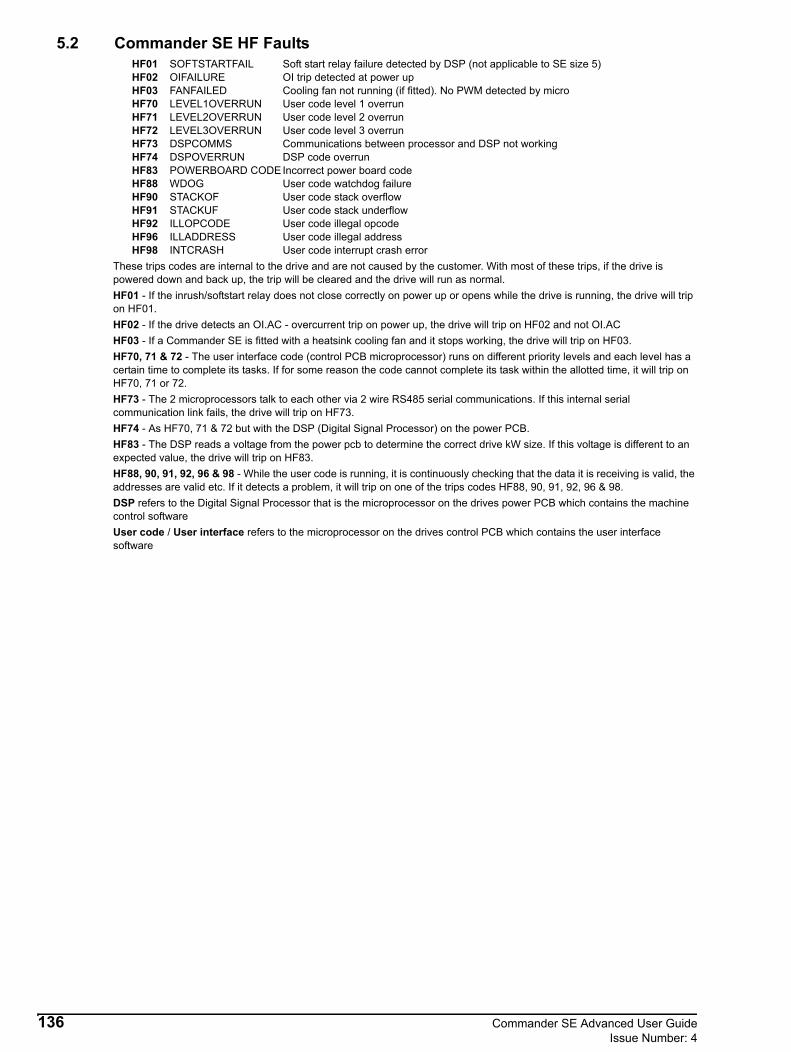
5.2 Commander SE HF FaultsHF01 SOFTSTARTFAIL Soft start relay failure detected by DSP (not applicable to SE size 5)HF02 OIFAILURE OI trip detected at power upHF03 FANFAILED Cooling fan not running (if fitted). No PWM detected by microHF70 LEVEL1OVERRUN User code level 1 overrunHF71 LEVEL2OVERRUN User code level 2 overrunHF72 LEVEL3OVERRUN User code level 3 overrunHF73 DSPCOMMS Communications between processor and DSP not workingHF74 DSPOVERRUN DSP code overrunHF83 POWERBOARD CODEIncorrect power board codeHF88 WDOG User code watchdog failureHF90 STACKOF User code stack overflowHF91 STACKUF User code stack underflowHF92 ILLOPCODE User code illegal opcodeHF96 ILLADDRESS User code illegal addressHF98 INTCRASH User code interrupt crash error
These trips codes are internal to the drive and are not caused by the customer. With most of these trips, if the drive is powered down and back up, the trip will be cleared and the drive will run as normal.HF01 - If the inrush/softstart relay does not close correctly on power up or opens while the drive is running, the drive will trip on HF01.HF02 - If the drive detects an OI.AC - overcurrent trip on power up, the drive will trip on HF02 and not OI.ACHF03 - If a Commander SE is fitted with a heatsink cooling fan and it stops working, the drive will trip on HF03.HF70, 71 & 72 - The user interface code (control PCB microprocessor) runs on different priority levels and each level has a certain time to complete its tasks. If for some reason the code cannot complete its task within the allotted time, it will trip on HF70, 71 or 72.HF73 - The 2 microprocessors talk to each other via 2 wire RS485 serial communications. If this internal serial communication link fails, the drive will trip on HF73.HF74 - As HF70, 71 & 72 but with the DSP (Digital Signal Processor) on the power PCB.HF83 - The DSP reads a voltage from the power pcb to determine the correct drive kW size. If this voltage is different to an expected value, the drive will trip on HF83.HF88, 90, 91, 92, 96 & 98 - While the user code is running, it is continuously checking that the data it is receiving is valid, the addresses are valid etc. If it detects a problem, it will trip on one of the trips codes HF88, 90, 91, 92, 96 & 98.DSP refers to the Digital Signal Processor that is the microprocessor on the drives power PCB which contains the machine control softwareUser code / User interface refers to the microprocessor on the drives control PCB which contains the user interface software
136 Commander SE Advanced User GuideIssue Number: 4

6 Input line reactorsLine reactors can be used to reduce supply harmonics and also should be used if any of the following conditions apply:• Supply capacity exceeds 200kVA• Fault current exceeds 5kA• Power-factor correction equipment is connected close to the drives• Large DC drives having no or ineffective line reactors connected to the supply• Direct on-line started motor(s) are connected to the supply and, when any of these motors are started, a dip is produced
in excess of 20% of the actual supply voltageDuring any of the above conditions, excessive peak current may flow in the input bridge. This may cause nuisance drive tripping or, in extreme cases, failure of the input bridge.A line reactor should then be connected in each phase of the supply to the input bridge. Line reactor(s) add the required impedance to the AC supply in order to reduce current transients to a level that can be tolerated by the input bridge. An impedance value of 2% is usually recommended.Three individual reactors, or a single three-phase reactor should be used. Each network of drives must have its own reactor(s).
RFI filters (for EMC purposes) do not give adequate protection against these conditions.
The following line reactors are available through Control Techniques:
Commander SE sizes 3, 4 and 5 drives include DC chokes, AC reactors are only required for harmonic reduction.
*These input line reactors are not stocked by Control Techniques. Therefore they should be ordered directly from the manufacturer, Skot Transformers, or sourced locally.
sales @skot.co.ukThey can be ordered using the above part numbers or Skot reference numbers:
Line reactors also improve the input current waveform and reduce the input current harmonic levels. Further information is included in the EMC Data Sheets.
Input line reactors for Harmonics standards EN61000-3-2 & IEC61000-3-2The following input line reactors allow the Commander SE 0.25 - 0.55kW drives to conform to harmonic standards EN61000-3-2 and IEC61000-3-2
EN61000-3-2 and IEC61000-3-2 applies to equipment with a supply voltage of 230VAC and a line current up to 16A, single or three phase. Professional equipment with rated input power exceeding 1kW has no limits - this applies to the 0.75kW drive.Further information on EN61000-3-2 and IEC61000-3-2 is included on the EMC data sheets available from your local Control Techniques Drive Centre or distributor.
CAUTION
Part Number Phases InductanceContinuous rms current
Peak current Weight
Drive used onA A kg lb
4402-0224 1 2.25 6.5 13 0.8 1.8 11200025, 11200037
4402-0225 1 1.0 15.1 30.2 1.1 2.4 11200055, 11200075, 2D200075, 2D200110
4402-0226 1 0.5 26.2 52.4 1.5 3.3 2D200150, 2D2002204402-0227 3 2.0 7.9 15.8 3.5 7.7 23400075, 23400110, 23400150
4402-0228 3 1.0 15.4 47.4 3.8 8.42D200075, 2D200110, 2D200150, 23400220, 23400300, 23400400, 33400550, 33400750
4402-0229 3 0.4 24.6 49.2 3.8 8.4 23200400, 2D200220, 33200550, 33200750
4402-0232 3 0.6 27.4 54.8 6 13 43401100, 43401500*4400-0240 3 0.45 46 92 7 15.5 43401850, 53402200*4400-0241 3 0.3 74 148 10 22 53403000, 53403700
CT Part Number Skot reference number
4400-0240 352324400-0241 35233
Drive Reactor part number
Drive power de-rating
Input power Inductance Continuous rms currentW mH
SE12200025 4400-0239 None 374 4.5 2.4SE12200037 4400-0238 None 553 9.75 3.2SE12200055 4400-0237 18% 715 16.25 4.5
NOTE
NOTE
Commander SE Advanced User Guide 137Issue Number: 4
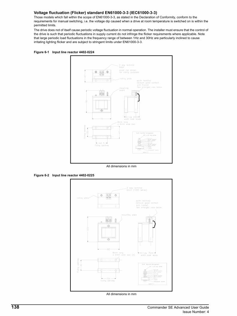
Voltage fluctuation (Flicker) standard EN61000-3-3 (IEC61000-3-3)Those models which fall within the scope of EN61000-3-3, as stated in the Declaration of Conformity, conform to the requirements for manual switching, i.e. the voltage dip caused when a drive at room temperature is switched on is within the permitted limits.The drive does not of itself cause periodic voltage fluctuation in normal operation. The installer must ensure that the control of the drive is such that periodic fluctuations in supply current do not infringe the flicker requirements where applicable. Note that large periodic load fluctuations in the frequency range of between 1Hz and 30Hz are particularly inclined to cause irritating lighting flicker and are subject to stringent limits under EN61000-3-3.
Figure 6-1 Input line reactor 4402-0224
All dimensions in mm
Figure 6-2 Input line reactor 4402-0225
All dimensions in mm
138 Commander SE Advanced User GuideIssue Number: 4
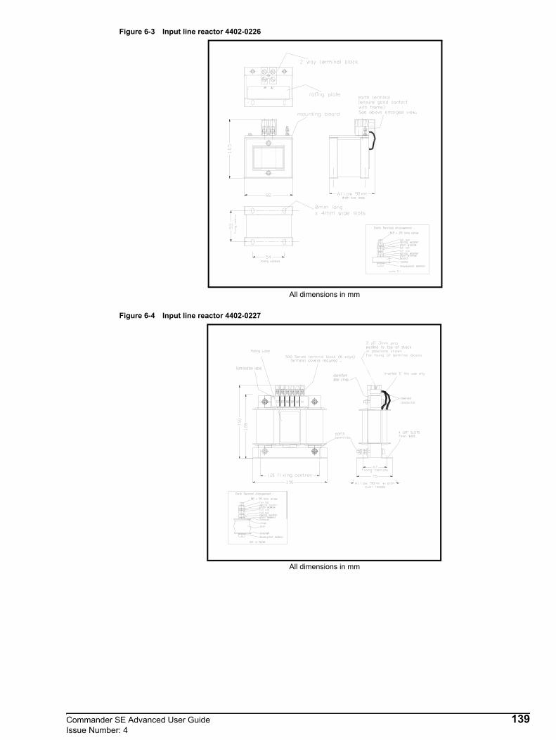
Figure 6-3 Input line reactor 4402-0226
All dimensions in mm
Figure 6-4 Input line reactor 4402-0227
All dimensions in mm
Commander SE Advanced User Guide 139Issue Number: 4

Figure 6-5 Input line reactor 4402-0228
All dimensions in mm
Figure 6-6 Input line reactor 4402-0229
All dimensions in mm
140 Commander SE Advanced User GuideIssue Number: 4

Figure 6-7 Input line reactor 4402-0232
All dimensions in mm
Figure 6-8 Input line reactor 4400-0240
All dimensions in mm
Commander SE Advanced User Guide 141Issue Number: 4

Figure 6-9 Input line reactor 4400-0241
All dimensions in mm.
142 Commander SE Advanced User GuideIssue Number: 4

7 Through-hole mounting platesThese should be manufactured locally, as per the following drawings, as they are not available through Control Techniques. (Not available for Commander SE size 1 and 5; size 5 can be through-hole mounted as standard.)
Figure 7-1 Commander SE Size 2
Figure 7-2 Commander SE Size 3
All dimensions in mm
All dimensions in mm
Commander SE Advanced User Guide 143Issue Number: 4

Figure 7-3 Commander SE Size 4
All dimensions in mm
144 Commander SE Advanced User GuideIssue Number: 4

8 Braking resistor bracketsDynamic braking resistor mounting bracketsDynamic braking resistor mounting brackets are available as an option for Commander SE Sizes 2, 3 and 4. These allow the SRF600 braking resistors to be mounted within the footprint of the drive and thus take up less cubicle space.The brackets can either mount directly onto the cubicle backplate or if a Schaffner RFI filter is being used, between the filter and the drive.These brackets are supplied as a kit with all the appropriate nuts, washers and spacers etc.
.
*Not available for Commander SE sizes 1 and 5
Commander SE Sizes 2, 3 and 4.
Drive CT Part Number Schaffner Part NumberCommander SE Size 2 6500-0358 295-988Commander SE Size 3 6500-0359 296-326Commander SE Size 4 6500-0360 296-327
Commander SE
Mountingbracket
Dynamicbraking resistors
Schaffner footprint filter
Commander SE Advanced User Guide 145Issue Number: 4

9 Dynamic braking resistorsSRF 600 zinc plated steel housed power wirewound resistor
The two lower wires in the diagram above, are connected internally to a Klixon bi-metallic switch (normally closed) which operates at 160°C, and resets at 140°C.The capability of the switch contacts is 6A @ 230 VACThis thermal switch must be used as part of a thermal protection circuit, removing the power supply from the drive when activated. Refer to Chapter 5 Dynamic Braking on page 132, for connection details.
Resistor values available
The resistors can be connected in series or parallel to give you the correct value required or a higher power rating. See Table 9-1 for minimum and recommended braking resistor values.When using the braking resistor mounting bracket as described in Chapter 8 Braking resistor brackets , it is advised that no more than two resistors are mounted on this plate. This will keep the amount of heat dissipated into the drive’s heatsink and into the RFI filter (if fitted) to an acceptable level.
These resistors are only recommended for a very light duty. They will certainly not be suitable for heavy braking, especially on the larger kW ratings of drives. Alternative higher power resistors should be sourced.
Resistor characteristics SRF600Power Rating 80WTemperature rise 160°CResistance tolerance ±5%Max. working voltage 1,000VInsulation resistance @ 1,000 VDC 1,000MΩ
Ohmic Value CT Part Number15Ω 1220-215320Ω 1220-220330Ω 1220-230340Ω 1220-240350Ω 1220-250375Ω 1220-2753
100Ω 1220-3103150Ω 1220-3153
57
13102
68
81
300
2.5mm2
NOTE
146 Commander SE Advanced User GuideIssue Number: 4

The information to be entered into parameters 10.30 Maximum full power braking time and 10.31 Maximum full power braking period for the protection of these resistors is given in the following tables. It can be seen that the ON time at 780VDC on certain resistor values* is too small to be entered into parameter 10.30. The range of parameter 10.30 is 0.0 to 400.0 in 100ms steps.The following ON times will increase the resistor element up to a temperature of 400°C. The following ‘duty cycles’ keep the resistor case temperature below the thermostat trip temperature of 160°C. If the following times and duty cycle are exceeded, the resistor thermostat will open.
Adiabatic ratingsThese resistors have a low adiabatic rating. The adiabatic rating is the amount of heat the resistor element can withstand in a single pulse without being damaged.Maximum ON timesThe following table gives the maximum ON times that the resistor can withstand without the element being damaged. The table also gives the minimum OFF times before the next pulse to ensure that the resistor element does not get damaged and also that the resistor case temperature does not exceed approx 160°C.
The following ON times will increase the resistor element up to a temperature of 800°C.
If these ON times are exceeded, the resistor will be damaged.
Alternative braking resistorsAlternative braking resistors can be sourced from the following braking resistor manufacturers:
Pentagon Electrical Products Ltdwww.pentagonelectric.co.ukCressall Resistorswww.cressall.comREOwww.reo.co.uk
Resistor TON @ 390VDC TOFF @ 390VDC TON @ 780VDC TOFF @ 780VDC
Ω ms s ms s15 110 32 28* 3220 135 29 34* 2930 199 25 50* 2540 218 23 54* 2350 343 23 86* 2375 249 18 62* 18
100 438 18 109 18150 479 15 120 15
Resistor TON @ 390VDC TOFF @ 390VDC TON @ 780VDC TOFF @ 780VDC
Ω ms s ms s15 220 56 55* 5620 270 51 67* 5130 398 42 99* 4240 436 40 109 4050 686 41 172 4175 497 31 124 31
100 876 31 219 31150 959 26 240 26
NOTE
Commander SE Advanced User Guide 147Issue Number: 4

Table 9-1 Commander SE braking resistor values
*Based on the recommended braking resistor value
Drive Minimum resistance (Ω)
Recommendedresistance (Ω)
Resistor peak power rating (W)*
SE2D200075 50 100 1.8SE2D200110 50 100 1.8SE2D200150 50 75 2.4SE2D200220 40 50 3.5SE23200400 30 30 5.9SE23400075 100 200 3.4SE23400110 100 200 3.4SE23400150 100 200 3.4SE23400220 75 100 6.9SE23400300 75 100 6.9SE23400400 75 100 6.9SE33200550 12 15 11.8SE33200750 12 15 11.8SE33400550 39 50 13.8SE33400750 39 50 13.8SE43401100 24 40 17.2SE43401500 24 30 23SE43401850 24 24 28.7SE53402200 10 20 34.5SE53403000 10 12 57.5SE53403700 10 12 57.5
148 Commander SE Advanced User GuideIssue Number: 4

10 EMC cable screening bracket and screening clampsEMC Screening bracket and screening clamps kitThe EMC screening bracket and screening clamps kits provide a convenient way of connecting supply, motor and control cable screens to ground (control cables only on size 5).
The kits will contain:
Commander SE Size 12 x M4 screws4 x 11.16mm cable clips1 x Size 1 cable screening bracket
Commander SE Size 22 x M4 screws4 x 11.16mm cable clips1 x Size 2 cable screening bracket
Commander SE Size 34 x M4 screws2 x SK20 screen terminal block2 x 11.16mm cable clips1 x Size 3 cable screening bracket
Commander SE Size 44 x M4 screws2 x SK20 screen terminal block3 x 11.16mm cable clips1 x Size 4 cable screening bracket
Commander SE Size 51 x M6 screw2 x 11.16mm cable clips1 x M6 nut1 x Size 5 cable screening bracket
Screen Terminal BlocksIncluded in the Size 3 and 4 kits are SK20 screen terminal blocks. They provide a very easy but more expensive method of connecting the cable screens to the screening bracket. Each screening bracket has been design to take either the SK14 or both the SK14 and SK20 screen terminal blocks.
Commander SE Size 1:5 x SK14 screen terminal blocks
Commander SE Size 2:4 x SK14 screen terminal blocks
Commander SE Size 3:3 x SK14 screen terminal blocks2 x SK20 screen terminal blocks
Commander SE Size 4:3 x SK14 screen terminal blocks2 x SK20 screen terminal blocks
Commander SE Size 5:2 x SK14 screen terminal blocks
These screening terminal blocks will take any diameter of cable up to the maximum of:SK14 14mm diameter cableSK20 20mm diameter cable
If these screen terminal blocks are preferred as an alternative to the cable clips, they can be purchased through Phoenix Contact.Phoenix Contact web site: www.phoenixcon.com
Drive Size Part Number Reference Number1 9500-0014 SE112 9500-0016 SE123 9500-0017 SE134 9500-0018 SE145 9500-0041 SE15
Commander SE Advanced User Guide 149Issue Number: 4
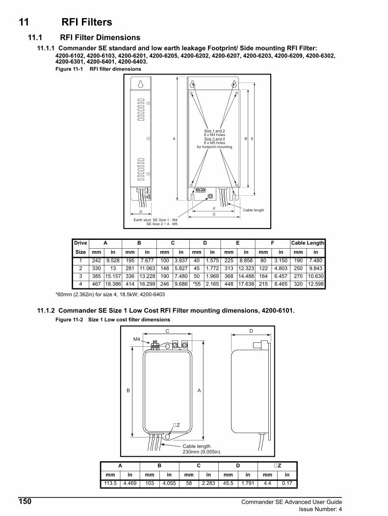
11 RFI Filters11.1 RFI Filter Dimensions
11.1.1 Commander SE standard and low earth leakage Footprint/ Side mounting RFI Filter: 4200-6102, 4200-6103, 4200-6201, 4200-6205, 4200-6202, 4200-6207, 4200-6203, 4200-6209, 4200-6302, 4200-6301, 4200-6401, 4200-6403.Figure 11-1 RFI filter dimensions
*60mm (2.362in) for size 4, 18.5kW; 4200-6403
11.1.2 Commander SE Size 1 Low Cost RFI Filter mounting dimensions, 4200-6101.Figure 11-2 Size 1 Low cost filter dimensions
Drive A B C D E F Cable Length
Size mm in mm in mm in mm in mm in mm in mm in1 242 9.528 195 7.677 100 3.937 40 1.575 225 8.858 80 3.150 190 7.4802 330 13 281 11.063 148 5.827 45 1.772 313 12.323 122 4.803 250 9.8433 385 15.157 336 13.228 190 7.480 50 1.969 368 14.488 164 6.457 270 10.6304 467 18.386 414 16.299 246 9.686 *55 2.165 448 17.638 215 8.465 320 12.598
DF
C
A B E
Size 1 and 2
Size 3 and 48 x M4 holes
8 x M5 holesfor footprint mounting
Cable length
Earth stud: SE Size 1 - M4SE Size 2 ~ 4 - M5
A B C D ∅ Z
mm in mm in mm in mm in mm in113.5 4.469 103 4.055 58 2.283 45.5 1.791 4.4 0.17
DC
AB
Cable length230mm (9.055in)
M4
∅ Z
150 Commander SE Advanced User GuideIssue Number: 4

11.1.3 Commander SE Size 2 and 3 Low cost single and three phase RFI Filter mounting dimensions, 4200-6204 and 4200-6304.Figure 11-3 RFI filter dimensions
11.1.4 Commander SE Size 2, 3 and 4 Low cost three phase RFI Filter mounting dimensions, 4200-6303, 4200-6402 and 4200-6404.Figure 11-4 RFI Filter Dimensions
Cable length4200-6204 = 250mm (9.843in)4200-6304 = 300mm (4.811in)
M5
∅ Z
A B C D E F G ∅ Zmm in mm in mm in mm in mm in mm in mm in mm in119 4.685 98.5 3.878 85.5 3.366 57.6 2.268 109 4.291 51 2 66 2.298 4.3 x 7.5 0.17 x 0.3
AB
C
D
E
F
G
H
Cable length300mm (11.811in)
M5
Z∅
A B C D E F G H ∅ Zmm in mm in mm in mm in mm in mm in mm in mm in mm in
4200-6303 133 5.236 120 4.724 118 4.646 70 2.756 80 3.150 103 4.055 90 3.543 130.6 5.142 6.5 0.2554200-6402 143 5.630 130 5.118 128 5.039 80 3.150 80 3.150 113 4.449 100 3.937 143 5.630 6.5 0.255
Commander SE Advanced User Guide 151Issue Number: 4

11.1.5 SE5340220 bookcase mounted filter, 4200-6116Figure 11-5 RFI filter dimensions
11.1.6 SE53403000 to SE53403700 bookcase mounted filter, 4200-6116Figure 11-6 RFI filter dimensions
C F
A
B
D
E
G
A B C D E F G ∅ Z
mm in mm in mm in mm in mm in mm in mm in mm in4200-6116 337 13.27 259.5 10.22 90 3.54 100 3.94 275 10.83 50 1.97 290 11.42 7 0.284200-6117 377 14.84 300 11.81 150 5.9 103 4.05 315 12.4 105 4.13 330 12.99 7 0.284200-6106 380 14.96 294 11.57 150 5.9 107 4.21 310 12.2 105 4.13 325 12.79 7 0.28
A
B
C
D
E
F
G
4200-6117 = M64200-6106 = M8
152 Commander SE Advanced User GuideIssue Number: 4

11.2 RFI Filter DataRFI filters are available as optional extra parts where required.
Table 11-1 Commander SE Size 1
Table 11-2 Commander SE Size 2 - 200V, 26A, 1 phase
Table 11-3 Commander SE Size 2 - 200 / 400V, 16A, 3 phase
Table 11-4 Commander SE Size 2 - 200 / 400V, 16A, 3 phase
Table 11-5 Commander SE Size 2 - 200V, 26A, 3 phase
Table 11-6 Commander SE Size 3 - 200V, 30A
Table 11-7 Commander SE Size 3 - 400V, 17A
Table 11-8 Commander SE Size 4
Table 11-9 Commander SE Size 5
Used with Filter Part No
Filter Type Mounting Max motor cable lengthStandard Low leakage Low cost Footprint Side m ft
SE11200025 to SE11200075
4200-6101 Y Y 20 664200-6102 Y Y Y 75 2464200-6103 Y Y Y 15 49
Used with Filter Part No
Filter Type Mounting Max motor cable lengthStandard Low leakage Low cost Footprint Side m ft
SE2D200075 to SE2D200220
4200-6201 Y Y Y 100 3304200-6204 Y Y 50 1644200-6205 Y Y Y 15 49
Used with Filter Part No
Filter Type Mounting Max motor cable lengthStandard Low leakage Low cost Footprint Side m ft
SE2D200075 to SE2D200220
4200-6202 Y Y Y 100 3304200-6304 Y Y 15 494200-6207 Y Y Y 45 148
Used with Filter Part No
Filter Type Mounting Max motor cable lengthStandard Low leakage Low cost Footprint Side m ft
SE23400075 to SE23400400
4200-6202 Y Y Y 100 3304200-6304 Y Y 15 494200-6207 Y Y Y 20 66
Used with Filter Part No
Filter Type Mounting Max motor cable length Standard Low leakage Low cost Footprint Side m ft
SE232004004200-6203 Y Y Y 100 3304200-6303 Y Y 20 664200-6209 Y Y Y 45 148
Used with Filter Part NoFilter Type Mounting Max motor cable length
Standard Low cost Footprint Side m ftSE33200550 to SE33200750
4200-6302 Y Y Y 100 3304200-6303 Y Y 15 49
Used with Filter Part NoFilter Type Mounting Max motor cable length
Standard Low cost Footprint Side m ftSE33400550 to SE33400750
4200-6301 Y Y Y 100 3304200-6304 Y Y 15 49
Used with Filter Part NoFilter Type Mounting Max motor cable length
Standard Low cost Footprint Side m ftSE43401100 to SE43401500
4200-6401 Y Y Y 100 3304200-6402 Y Y 15 49
SE434018504200-6403 Y Y Y 100 3304200-6404 Y Y 20 66
Used with Filter Part NoFilter Type Mounting Max motor cable lengthStandard Bookcase m ft
SE53402200 4200-6116 Y Y 100 330SE53403000 4200-6117 Y Y 100 330SE53403700 4200-6106 Y Y 100 330
Commander SE Advanced User Guide 153Issue Number: 4

Further data for the filters is given in the following tables:
Table 11-10 Commander SE Size 1
Table 11-11 Commander SE Size 2
Table 11-12 Commander SE Size 3
*Also used on Size 2 units.
Table 11-13 Commander SE Size 4
Table 11-14 Commander SE Size 5
Discharge resistors1.5MΩ in a star connection between phases with star point connected by a 680kΩ resistor to ground.
This may cause an earth leakage indication in monitored ungrounded power systems such as IT systems.
For tables 11-9 to 13-14, please be aware of the following: Weight is unpacked weight. Worst case leakage current:Single phase filters - when the neutral is disconnected. Three phase filters - when an input phase is disconnected.The data is given for an input voltage of 230V, 50Hz.
Part Number
Maximum Power Losses
IP Rating WeightOperational
Leakage Current
Worst Case Leakage Current
Filter Terminal Tightening Torque
Filter current rating
W kg lb mA mA Nm lb ft A4200-6101 6 21 0.49 1.1 4.0 8.0 0.8 0.6 124200-6102 6 20 0.60 1.3 40.7 77.5 0.8 0.6 124200-6103 6 21 0.60 1.3 2.9 5.7 0.8 0.6 12
Part Number
Maximum Power Losses
IP Rating WeightOperational
Leakage Current
Worst Case Leakage Current
Filter Terminal Tightening Torque
Filter current rating
W kg lb mA mA Nm lb ft A4200-6201 10.1 20 1.2 2.6 89 128 0.8 0.6 264200-6202 10.1 20 1.1 2.4 45.7 184.2 0.8 0.6 164200-6203 15.4 20 1.3 2.9 26.4 106.3 0.8 0.6 264200-6204 6 20 0.7 1.5 29.5 58.9 0.8 0.6 264200-6205 10.1 20 1.2 2.6 2.8 5.7 0.8 0.6 264200-6207 10.1 20 1.1 2.4 3 18.3 0.8 0.6 164200-6209 15.4 20 1.3 2.9 2.6 15.5 0.8 0.6 26
Part Number
Maximum Power Losses
IP Rating WeightOperational
Leakage Current
Worst Case Leakage Current
Filter Terminal Tightening Torque
Filter current rating
W kg lb mA mA Nm lb ft A4200-6301 12.4 20 1.6 3.5 45.7 184.2 0.8 0.6 174200-6302 19.5 20 1.7 3.7 26.4 106.3 0.8 0.6 304200-6303* 10.8 20 0.8 1.7 14.1 68 0.8 0.6 304200-6304* 6.1 20 0.6 1.3 33 148 0.8 0.6 17
Part Number
Maximum Power Losses
IP Rating WeightOperational
Leakage Current
Worst Case Leakage Current
Filter Terminal Tightening Torque
Filter current rating
W kg lb mA mA Nm lb ft A4200-6401 26.1 20 3.1 6.8 29.4 280 2.2 1.6 334200-6402 11.7 20 1.1 2.4 14.1 68 2.2 1.6 334200-6403 30 20 3.1 6.8 38 220 2.2 1.6 374200-6404 16 20 1.2 2.6 24.5 132 2.2 1.6 37
Part Number
Maximum Power Losses
IP Rating Weight
Operational Leakage Current
Worst Case Leakage Current
Terminal Torques
Ground Connection
Torque
Filter current rating
W kg lb mA mA Nm lb ft Nm lb ft A4200-6116 12.8 20 3.8 9 31 143 4.5 3.3 2.2 1.6 504200-6117 14.3 20 3.8 9 29 126 4.5 3.3 4.0 2.9 634200-6106 25.5 20 7.8 17 48.5 209 8.0 5.9 9.0 6.6 100
NOTE
NOTE
154 Commander SE Advanced User GuideIssue Number: 4

11.3 Multiple motor applicationsWhen more than one motor is to be connected to the output terminals of one drive, the following wiring recommendations should be followed to ensure that the drive is not prone to spurious overcurrent tripping and that the motors are thermally protected.
Figure 11-7
Figure 11-8
It is recommended that a single cable is used to serially connect all motors as in Figure 11-7 rather than individual cables from the drive to each motor as in Figure 11-8.Where the motors are connected as in Figure 11-7, the total length of the cable should not exceed the recommended maximum cable length for the drive. If the length does not exceed the recommended maximum cable length, then an output inductor should be used.Where it is unavoidable to use individual cables to each motor as in Figure 11-8, an output line inductor must be used, see Figure 11-9. When the cables and motors are connected in this way, the overall inductance of the cables get smaller because they are connected in parallel. This has the effect of making the cable capacitance charging currents larger, which may cause spurious OI.AC trips.In a multiple motor application, individual thermal overloads must be fitted as in Figure 11-7 and Figure 11-9 to protect each individual motor. To avoid premature operation of the thermal overloads because of the cable capacitance charging currents, they should be connected at the motor end of the cables, and as close to the motor as possible.
Thermal overloads
Thermal overloads
Commander SE Advanced User Guide 155Issue Number: 4

Figure 11-9
The following calculations can be used to calculate the correct value of output line inductor.
Step 1Estimate the cable capacitance - from one line to all others.Typical values:Multi-core cables, and screened armoured cables where there is a plastic sheath between the phases and the screen: 130pF/mScreened cables with no plastic sheath between cores and screen, mineral insulated cables: 300pF/mAdd an allowance for the motor capacitance. This depends on the motor size, but we suggest a value of 1nF per motor is a reasonable estimate. This will usually be rather smaller than the cable capacitance.
Step 2Decide on the available charging current from the drive. This depends to some extent on the application and the drive. Here is the typical procedure for Commander SE:
Where:In is the nominal rated rms drive output currentk is the acceptable short-term overload factor.
The drive is rated for 150%, i.e. k = 1.5, but increased cable driving capability is achieved if this can be reduced. For many applications 1.25 is acceptable and for fan/pump applications, 1.1 may be acceptable.In the case where the drive has been de-rated to allow for the long cable, i.e. a larger than normal drive is used, a lower value of k will be appropriate. It should be the ratio of the expected maximum short-term torque to the (theoretical) rated torque capability of the drive.The factor 2.1 in the expression is the ratio of drive instant trip current to nominal output current, for Commander SE.
Step 3Decide the maximum DC link voltage where the drive is required to produce full torque. This will normally be 1.41 times the highest AC supply voltage.
Step 4The minimum value of inductance (per phase) is given by the expression:
If using standard iron-cored chokes, the inductance at the high frequencies involved will be rather lower than the specified 50/60Hz inductance. We suggest specifying an inductance of twice that determined by this calculation i.e. 2Lmin
Thermal overloads
Outputline
inductor
Ich 1.41In 2.1 k–( )=
Lmin2C3
-------- VdcIch
----------- 2
=
156 Commander SE Advanced User GuideIssue Number: 4

Step 5The maximum value of inductance is determined by the acceptable voltage drop at the working frequency. Calculate it from the following expression:
Where:x is acceptable voltage drop fraction e.g. for 5% use 0.05Vac is motor voltage rating (line to line)fo is maximum drive output frequency
Since the voltage drop is inductive, it does not subtract directly from the motor terminal voltage. A value of k of 0.05 is generally acceptable. If the application is very critical to obtaining full rated torque at full speed then it may be advisable to apply a lower value of k e.g. 0.02
Step 6If 2Lmin < Lmax then any value between these limits can be used. This may be helpful in allowing a small number of standard values to be held in stock to cover most applications.If there is a need to minimise the high frequency current, for example to prevent premature operation of thermal relays, then the highest value should be used.If 2Lmin > Lmax then the drive cannot operate with this length of cable and a higher rated drive must be used. Choose the value of L.
Step 7Consideration must now be given to the high frequency losses in the chokes. The loss in each choke can be estimated from the following expression:
P = 0.8fsCV2DC where
Fs = switching frequencyThe factor 0.8 is a rough estimate of the fraction of the total losses which are dissipated in the choke. Note that the loss is proportional to the switching frequency so the lowest acceptable frequency should be selected.
Step 8It is now necessary to decide whether the choke is able to tolerate this loss. This is a difficult judgement. As a crude rule, the loss should not exceed 0.1 of the VA in the choke at maximum speed, i.e.
P = <0.2fo(max) x L x In x InWhere:
fo(max) = maximum output frequency
If the loss exceeds this limit, and it is not possible to reduce the switching frequency, then a resistor should be connected in parallel with the choke to extract some of the power.The resistor value is given by:
The value is not critical and variations of ±50% are acceptable.The power rating of the resistor should be at least 0.8P.Provision must be made for the resistor to dissipate this power without overheating itself or nearby equipment. Values of 100W per phase are not uncommon.
ExampleA Commander SE 7.5kW with 8 motors of 0.75kW each connected by 140m of multi-core cable. 380VAC supply, maximum output frequency 50Hz, switching frequency 6kHz. Thermal relays in all motor circuits.
Step 1Cable capacitance 130 x 140 x 8 = 0.146uF = 0.154uFMotor capacitance 1nF x 8 = 0.008uF= 0.154uF
Step 2Use k = 1.25 (note motor power total is only 6kW)In = 16A = 19.2A
Step 3380VAC +10% x 1.41= 591V
LmaxxVac
2πfo 3In--------------------------=
R 2LC
-------=
Commander SE Advanced User Guide 157Issue Number: 4

Step 4 = 97uH
Step 5Use x = 0.05= 2.18mH
Step 6194uH < 2.18mH so any value in this range is acceptable. Use 2mH to minimise the heating of the thermal relays.
Step 7P = 258W
This is excessive, so reduce the switching frequency to 3kHz giving 129W.= 129W
Step 80.2πfo(max) LIn2 = 16W so heating would be excessive.R = 161Ω so use 150Ω or 180Ω with a power rating 150W.
Drive set-upThe Commander SE should be set up into fixed boost mode when operated in a multi-motor application. Set parameter 5.14 = 2 and perform a save routine. The boost level parameter 5.15 may need adjusting depending on the size of the motors.
158 Commander SE Advanced User GuideIssue Number: 4

12 Applications
External Menu parameters can only be accessed via the Universal Keypad, SE Soft or high speed comms options cards.
12.1 Connecting digital inputs in parallelMake the following connections when the digital inputs of a number of Commander SE drives are to be controlled from the same source:• Connect the relevant digital input (e.g. terminal 10) on all the drives in parallel.• Use an external +24V supply, or use the +24V output supply on terminal 7. When using terminal 7 for more than three
drives, connect in parallel terminal 7 from a number of drives. Make each connection through a 300mA diode. For each additional three drives, connect another terminal 7 through a diode.
• Ensure that the controlling signal produces definite logic states; a logic state must not be assumed by leaving an input disconnected (e.g. use achange-over relay, not a single contact).
Provided these conditions are met, any number of drives can be controlled in parallel using positive or negative logic.
Figure 12-1 Example parallel signal connections using the 24V supply of the drive
Figure 12-2 Example parallel signal connections using an external 24V supply
NOTE
Drive 1
7101
+24V output
Run forward
0V common
Drive 2
7101
+24V output
Run forward
0V common
Drive 4
7101
+24V output
Run forward
0V common
Drive 3
7101
+24V output
Run forward
0V common
Commander SE Advanced User Guide 159Issue Number: 4

12.2 How to re-assign drive terminal input/output functions
12.2.1 Digital inputsTo aid the ease of set-up of the digital input terminals of Commander SE, it has two parameters that automatically change the functionality of the digital inputs to suit the majority of applications. This allows a number of combinations of terminal set-ups to be achieved by only changing two parameters. Obviously there will be occasions when these set-ups are not what is required and an alternative set-up is required.Parameter 6.04 (parameter 35) automatically changes the functionality of terminals 9, 10 and 11.
Parameter 1.14 (parameter 05) automatically changes the functionality of terminals 12 and 13 when parameter 8.39 = 0.
The Commander SE also has the flexibility to allow the user to change the function of the drives digital input terminals to the functionality that is required.
Terminals 9, 10 and 11Example
It may be required that:terminal 9 = Runterminal 10 = /Stopterminal 11 = Reset
To allow the user to change the functionality of terminals 9, 10 and 11, parameter 6.04 must be changed to 4 and saved. This disables the automatic set-up of terminals 9, 10 and 11.
6.04 = 4Perform a save routine: xx.00 = 1000 and press the red Stop/Reset button on the drive.
8.22 = 6.34 Assigns the Run function to terminal 98.23 = 6.39 Assigns the /Stop function to terminal 108.24 = 10.33 Assigns the reset function to terminal 11At this stage, the setting of parameter 6.40 - Enable latching run inputs should be considered and set as required.
Perform a save routine: xx.00 = 1000 and press the red Stop/Reset button on the drive.
Terminals 12 and 13Example
It may be required that:terminal 12 = Forward / Reverseterminal 13 = Enable
To allow the user to change the functionality of terminals 12 and 13, parameter 8.39 must be changed to 1. This disables the automatic set-up of terminals 12 and 13.
8.39 = 18.25 = 6.33 Assigns the Forward / Reverse function to terminal 128.26 = 6.29 Assigns the Enable function to terminal 13
Perform a save routine: xx.00 = 1000 and press the red Stop/Reset button on the drive.
6.04 Terminal 9 Terminal 10 Terminal 11 Parameter 6.40
0 (default) Enable Run Forward Run Reverse 0 (non latching)
1 /Stop Run Forward Run Reverse 1 (latching)
2 Enable Run Reverse 0 (non latching)
3 /Stop Run Reverse 1 (latching)
4 User Programmable User Programmable User Programmable User Programmable
Parameter 1.14 Terminal 12 Terminal 13
0 Local/Remote Jog
1 Preset speeds Preset speeds
2 Preset speeds Preset speeds
3 Preset speeds Preset speeds
4
5
160 Commander SE Advanced User GuideIssue Number: 4

12.2.2 Digital outputsAs default, the digital output on terminal 8 is set-up as a zero speed output and the relay output on terminals 15 and 16 is set-up as a drive healthy relay. These two outputs can be re-assigned as required:Example
It may be required thatterminal 8 = Drive running indicatorterminals 15 and 16 = at speed relay
8.21 = 10.02 Assigns terminal 8 as a drive running indicator8.27 = 10.06 Assigns terminals 15 and 16 as an at speed indicator
Perform a save routine: xx.00 = 1000 and press the red Stop/Reset button on the drive.
Terminal 8 as a digital inputTerminal 8 can also be set-up as a digital input if required.
8.31 = 0 Assigns terminal 8 as a digital input
Perform a save routine: xx.00 = 1000 and press the red Stop/Reset button on the drive.
12.2.3 Analog outputAs default, the analog output on terminal 6 is set-up as an indication of motor speed. The analog output is automatically set-up by the setting of parameter 7.33 (parameter 36).
ExampleIt may be required that the analog output gives an indication of DC bus voltage.
7.33 = 2 Allows terminal 6 to be user programmable7.19 = 5.05 Assigns terminal 6 to give a voltage output proportional to DC bus voltage
Perform a save routine: xx.00 = 1000 and press the red Stop/Reset button on the drive.
12.2.4 Analog inputAs default, the voltage reference on terminal 2 controls analog reference 1 which is called the local speed reference. The cur-rent reference on terminal 5 controls analog reference 2 which is called the remote speed reference. Both of these inputs can be re-assigned as desired.
ExampleIt is required that the drives speed reference is controlled by the current reference on terminal 5 and the voltage reference on terminal 2 controls the current limit.
7.10 = 4.07 analog input 1 assigned to the current limit
Perform a save routine: xx.00 = 1000 and press the red Stop/Reset button on the drive.
Exactly the same thing could be achieved if the drives speed reference was to be controlled by the voltage reference on ter-minal 2 and the current reference on terminal 5 was to control the current limit.
7.14 = 4.07 analog input 2 assigned to the current limit
Perform a save routine: xx.00 = 1000 and press the red Stop/Reset button on the drive.
12.3 Commander SE user tripsParameter 10.38User trips are from 40 to 99. If the user sends via serial communications the value 40 to 99 to parameter 10.38, the drive will trip and display
tr txxwhere xx is the trip code.
If the user sends a value via serial communications to parameter 10.38 which already has a trip code associated with it, then the drive will trip on this trip code i.e. if the user sends 1 to 10.38, the drive will trip on
tr UUSee information after parameter 10.29 for trip codes.
Parameter 7.33 Parameter 7.19 Analog output
Fr 2.01 A voltage proportional to motor speed
Ld 4.02 A voltage proportional to motor load
AdV User programmable User requirement
Commander SE Advanced User Guide 161Issue Number: 4

12.4 Analog input 2Analog input 2 is the remote current input, which is fed into terminal 5 on the control terminals. This input has 6 modes, which can be selected.
If the 4 – 20 or 20 – 4mA modes are selected, the drive will trip on cL if the input reference is less than 3mA. If the drive trips on cL, analog reference 1 cannot be selected.If the 4 - .20 or 20 - .4mA modes are selected, the drive will not trip on cL if the input reference is less than 3mA. This will allow analog reference 1 to be selected if analog reference 2 fails. A bit parameter, parameter 7.28 Current loop loss indicator is provided so that this can be programmed to a digital output to give a signal if the analog 2 reference falls below 3mA.
Parameter set-upParameter 8.21 = parameter 7.28Perform a Save routine: xx.00 = 1000 and press red Stop / Reset button on the driveConnectionsControl signal terminal block.
OperationWhen the current into terminal 5 falls below 3mA, terminal 8 will go to +24V and therefore light the LED. The signal from terminal 8 could go to a PLC or other type of signal monitoring system. The PLC or signal monitoring system could then automatically switch terminal 12, Local/Remote speed reference select, to select analog reference 1 on terminal 2 so that the application can keep running with the minimum of downtime.
AlternativelyIf it is required that the drive trips on cL and the reference must be changed back to analog reference 1 to allow the application to continue running, the variable selector can be used to achieve this.
Set-up from default1.21 = 0.2 Preset speed 1 to 0.21.22 = 0.4 Preset speed 2 to 0.48.39 = 1 Disable automatic set-up of terminals 12 and 138.26 = 12.10 Terminal 13 to control variable selector select bit12.08 = 1.21 Variable select source 1 from preset speed 112.09 = 1.22 Variable select source 2 from preset speed 212.11 = 7.11 Variable select output to analog input 2 mode selector
Perform a Save routine: xx.00 = 1000 and press red Stop / Reset button on the drive
OperationFrom default operation:The drive will be running from a 4-20mA signal into terminal 5 with terminal 12 (Local/Remote) closed. If the 4-20mA signal falls below 3mA, the drive will trip on cL. Terminal 13 can then be closed so that variable selector out will select 4-20mA without cL trip on parameter 7.11 (4-.20). Then terminal 12 can be opened and the drive reset so that it can run from a 0 to 10V input on terminal 2.
Mode Description0 – 20 Current input 0 to 20mA (20mA full scale)20 – 0 Current input 20 to 0mA (0mA full scale)4 – 20 Current input 4 to 20mA with current loop loss (cL) trip (20mA full scale)20 – 4 Current input 20 to 4mA with current loop loss (cL) trip (4mA full scale)4 - .20 Current input 4 to 20mA with no current loop loss (cL) trip (20mA full scale)20 - .4 Current input 20 to 4mA with no current loop loss (cL) trip (4mA full scale)
162 Commander SE Advanced User GuideIssue Number: 4

12.5 Drive overload alarm signal connectionThe digital output or the status relay can be set-up to signal an alarm output such as drive temperature alarm 'hot', drive overload alarm 'OVL' or braking resistor overload 'br.rS'.
Example 1To provide a digital output signal when the drive goes into current overload.
Parameter settingsSet parameter 8.21 to parameter 10.17Perform a Save routine: xx.00 = 1000 and press red Stop / Reset button on the drive
ConnectionsControl signal terminal block
OperationWhen the drive goes into current overload and OVL flashes on the display, terminal 8 will go to +24V and therefore light the LED. The signal from terminal 8 could be go to a PLC or other type of signal monitoring system.
Example 2To provide a signal when the drive goes into current overload using the drives status relay.
Parameter settingsSet parameter 8.27 to parameter 10.17Perform a Save routine: xx.00 = 1000 and press red Stop / Reset button on the drive
ConnectionsControl signal terminal block
OperationWhen the drive goes into current overload and OVL flashes on the display, the relay will close and therefore light the LED. The signal from the +24V rail through the relay could be go to a PLC or other type of signal monitoring system.
12.6 Motor thermistor set upTerminal 13 (digital input 6) can be used as a motor thermistor input. To set this up, set parameter 50 = ON. Connect the motor thermistor between 0V (terminals 1 or 4) and terminal 13.
The trip resistance is approximately 3k and the reset resistance is approximately 1k8.The input does not have Motor thermistor short circuit protection. Therefore if the motor thermistor goes short circuit, the drive will not trip out on ‘th’. The motor thermistor going short circuit will not damage the drive.There is not a parameter to display the motor temperature.The motor thermistor can also be enabled through the advanced menus by setting parameter 8.40 = 1 and performing a save by setting xx.00 to 1000 and pressing the Stop/Reset button.
1 8 14
PLC
1 8 14
PLC
15 16
Commander SE Advanced User Guide 163Issue Number: 4

12.7 Drive set-up for 8 preset speedsParameter set up
8.39 = 1 (disable auto set-up of terminals 12 and 13).6.04 = 4 (allow terminals 9,10 and 11 to be programmed).Perform a Save routine: xx.00 = 1000 and press red Stop / Reset button on the drive8.26 = 1.47 (Terminal 13).8.25 = 1.46 (Terminal 12).8.24 = 1.45 (Terminal 11).1.14 to Pr, Mode 3 (allows the above terminals to control preset speeds).1.21 = ? (required preset speed 1).1.22 = ? (required preset speed 2).1.23 = ? (required preset speed 3).1.24 = ? (required preset speed 4).1.25 = ? (required preset speed 5).1.26 = ? (required preset speed 6).1.27 = ? (required preset speed 7).1.28 = ? (required preset speed 8).Perform a Save routine: xx.00 = 1000 and press red Stop / Reset button on the drive
If a negative value speed is required then set parameter 1.10 = 1 (Enable negative preset speeds).
0 = Switch open1 = Switch closed
The relative preset speed will be selected according to the sequence of switch settings on terminals 11, 12 and 13.Terminals 9 (Enable) and 10 (Run Forward) will need to be connected to +24V for the drive to run.
12.8 Utilising dual motor set-upThe Commander SE has the ability to control 2 different motors of different ratings, so long as they are both within the specification of the drive. Only one motor can be controlled at any one time. The motor 2 parameters should be entered in Menu 21.A digital input should be programmed to 11.45 to select the second motor map. The second motor map will only be implemented when the drive is in the inhibit, ready or tripped modes.A parameter in Menu 21, 21.15, will change from a 0 to a 1 when the second motor map is implemented. This can be used to change a changeover relay which intern will select the correct motor contactor.See diagram on the next page.
Parameter set-up8.39 = 1 Disable automatic set-up of terminals 12 and 138.26 = 11.45 Terminal 13 to select second motor map.8.21 = 21.15 Digital output to second motor map implementedPerform a Save routine: xx.00 = 1000 and press red Stop / Reset button on the drive
Enter motor 1 nameplate details into motor map parameters in level 1 or Menu 5 with motor 1 selected and perform an autotune (0.38 = 1[non rotating] or 2 [rotating])Enter motor 2 nameplate details into motor map 2 in Menu 21 and with motor 2 selected perform an autotune (0.38 = 1[non rotating] or 2 [rotating])
OperationWhen the switch on terminal 13 is open, the external relay will be de-energised and therefore the contactor to motor 1 will be closed.If the drive is running and the switch on terminal 13 is closed, the contactor to motor 1 will remain closed. If the drive is stopped or disabled, the external relay will energise and open the contactor to motor 1 and close the contactor to motor 2.This set-up ensures that the drive is disabled when the contactors are opened or closed.
Terminal 13 Terminal 12 Terminal 11 Preset Speed0 0 0 10 0 1 20 1 0 30 1 1 41 0 0 51 0 1 61 1 0 71 1 1 8
164 Commander SE Advanced User GuideIssue Number: 4
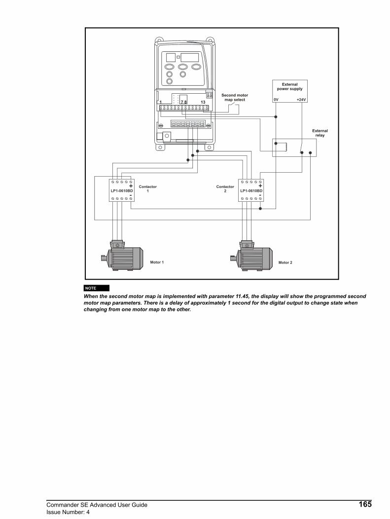
When the second motor map is implemented with parameter 11.45, the display will show the programmed second motor map parameters. There is a delay of approximately 1 second for the digital output to change state when changing from one motor map to the other.
0V +24V
LP1-0610BD+-
LP1-0610BD+-
Contactor2
Contactor1
Motor 2Motor 1
8Second motor
map select
Externalrelay
1 137
Externalpower supply
NOTE
Commander SE Advanced User Guide 165Issue Number: 4

12.9 Commander SE analog output offset scalerExample 1The Commander SE does not have an offset trim parameter, so in order to achieve this function the drive’s internal PID loop can be used. For this example the analog output on terminal 6 is required to give 0-10V (0-50Hz) when the analog input goes from 5.5V-10V.Parameter set up
7.10 = 01.28 = 550.0 Offset using preset speed 8 calculated by:
Required voltage level @ 0Hz / Maximum voltage value of analog output x 1000 (Range of 1.28)14.03 = 7.01 PID reference source assigned to analog input 114.04 = 1.28 PID feedback source assigned to preset speed 814.10 = 1.00 PID proportional gain14.11 = 0 PID integral gain14.12 = 0 PID derivative gain14.13 = 45% PID output limited to 45% of total value14.14 = 0 PID output can never go negative14.15 = 2.22 Output from the PID is scaled back to the full range of the frequency reference, calculated by:
Max range of 14.15 / 14.1314.16 = 1.36 PID output destination assigned to analog reference 114.08 = 1 Enable PIDPerform a Save routine: xx.00 = 1000 and press red Stop / Reset button on the drive
7.01
14.03
1.28
14.04
5.5V10V 1000 = 550.0X
Offset using 1.28
14.08 EnablePID
14.10
14.12 = 014.11 = 0
= 1.00
Subtractor
+
_14.15
14.10 14.13
= 0= 45%
Clamp
100%45% = 2.22
Scale back to full range of
frequency reference
14.16= 1.36
166 Commander SE Advanced User GuideIssue Number: 4
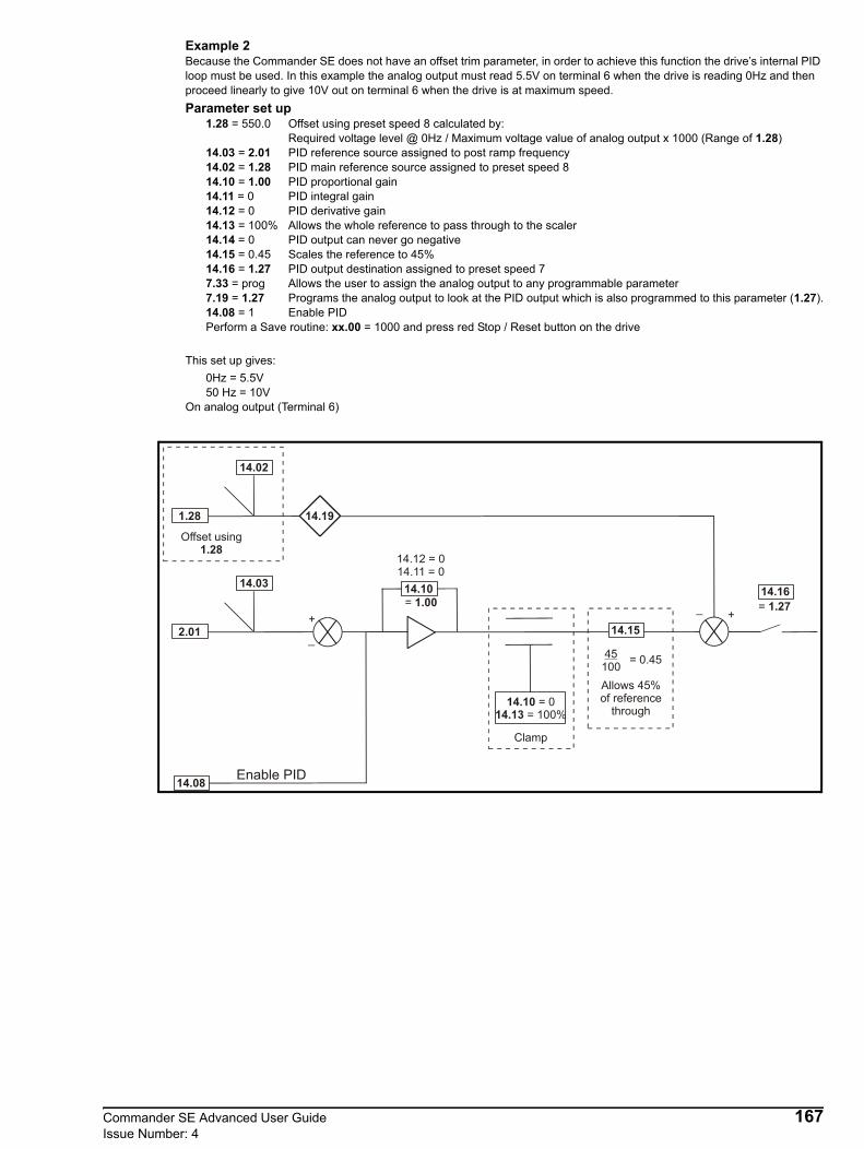
Example 2Because the Commander SE does not have an offset trim parameter, in order to achieve this function the drive’s internal PID loop must be used. In this example the analog output must read 5.5V on terminal 6 when the drive is reading 0Hz and then proceed linearly to give 10V out on terminal 6 when the drive is at maximum speed.Parameter set up
1.28 = 550.0 Offset using preset speed 8 calculated by: Required voltage level @ 0Hz / Maximum voltage value of analog output x 1000 (Range of 1.28)
14.03 = 2.01 PID reference source assigned to post ramp frequency14.02 = 1.28 PID main reference source assigned to preset speed 814.10 = 1.00 PID proportional gain14.11 = 0 PID integral gain14.12 = 0 PID derivative gain14.13 = 100% Allows the whole reference to pass through to the scaler14.14 = 0 PID output can never go negative14.15 = 0.45 Scales the reference to 45%14.16 = 1.27 PID output destination assigned to preset speed 77.33 = prog Allows the user to assign the analog output to any programmable parameter7.19 = 1.27 Programs the analog output to look at the PID output which is also programmed to this parameter (1.27).14.08 = 1 Enable PIDPerform a Save routine: xx.00 = 1000 and press red Stop / Reset button on the drive
This set up gives:0Hz = 5.5V50 Hz = 10V
On analog output (Terminal 6)
14.03
2.01
14.08 Enable PID
14.10
14.12 = 014.11 = 0
= 1.00+
_14.15
14.10 14.13
= 0= 100%
Clamp
45100 = 0.45
Allows 45%of reference
through
14.16= 1.27
14.02
1.28
Offset using 1.28
14.19
+_
Commander SE Advanced User Guide 167Issue Number: 4

12.10 Brake set-up parameters12.10.1 Brake set-up 1
Great care should be taken when implementing a brake control set-up as this may cause a safety issue depending on the application, e.g. crane. If in any doubt, please contact the supplier of the drive for advice and information.
The following set-up should only be used in non-safety critical applications.
3.05 = 2.0 Zero speed threshold set to 2Hz (set to appropriate frequency as necessary)8.21 = 9.01 Brake release output on terminal 8 - digital output9.04 = 10.03 Logic function source 1 = zero speed9.05 = 1 Logic function 1 source invert9.06 = 12.01 Logic function source 2 = threshold level exceeded9.09 = 0.2 Logic function delay of 0.2 seconds12.03 = 4.01 Threshold source is motor current magnitude12.04 = 10 Threshold level set to 10% (set to appropriate level as necessary)12.05 = 10 Hysteresis level set to 10% (set to appropriate frequency as necessary)Perform a Save routine: xx.00 = 1000 and press red Stop / Reset button on the drive
From the above:Brake release = Drive healthy & not zero speed (>2Hz) & 4.01 > threshold
The digital output signal MUST be fed through the drive healthy relay and should drive an external relay coil. The contacts of this relay should feed the brake.When the drive is healthy, the drives status relay will be closed. When the drives speed goes above 2Hz and the current magnitude goes above the threshold, the digital output will go high. This will release the mechanical brake.If the speed falls below 2Hz or the current falls below the threshold level, the digital output will go low engaging the brake. If the drive trips while running, the status relay will open again causing the brake to be engaged.
This set-up is appropriate for forward or reverse applications but can cause an issue if you go from forward to reverse as the brake can pulse on when the motor speed falls below the set zero speed threshold. If this is the case, the next example using external circuitry must be implemented.
WARNING
NOTE
Powersupply
1615
ExternalrelayN/O
Drive HealthyrelayN/O
Digitaloutput
Motor (Brake)
U V W
168 Commander SE Advanced User GuideIssue Number: 4

12.10.2 Brake set-up 2The following set-up is an alternative to the set-up on the previous page.
Great care should be taken when implementing a brake control set-up as this may cause a safety issue depending on the application, e.g. crane. If in any doubt, please contact the supplier of the drive for advice and information.
Frequency ReferenceUsually by analog reference of preset speeds. The run forward and/or run reverse inputs must be used to change the direction of motor rotation. Changing the direction of rotation by the sign of the analog input is not advisable for safety reasons.
Brake ControlIMPORTANT INFORMATION!• Connect a +24V interface relay to the Commander SE according to the connection diagram on the following page. • Control the brake contactor according to the diagram on the following page. • The programming of the Drive Healthy relay should not be changed, it should remain as a Drive Healthy relay.• Make sure that the Drive Healthy relay of the Commander SE inhibits the brake contactor.• Use a separate overspeed detection which is integrated into the emergency stop circuit.• Use DC control of the brake coil to improve brake response.• Fast ramps must be selected to stop extended travel due to the drives internal DC bus controller becoming active and
increasing the ramp times automatically.
Commissioning and drive set-up• Connect the Commander SE according to the connection diagram on the following page.• Disconnect the coil connecting the brake contactor.• Program the following parameters:
02 = set the appropriate motor rated frequency06 = set the appropriate motor rated current07 = 0 disable slip compensation08 = set the appropriate motor rated voltage09 = set the appropriate motor rated power factor30 = 0 (FASt) Set fast ramps
8.21 = 9.01 Digital output source from programmable logic output indicator9.04 = 12.01 Programmable logic source 1 from programmable threshold indicator9.06 = 10.03 Programmable logic source 2 from zero speed indicator9.07 = 1 Programmable logic source 2 invert12.03 = 4.01 Threshold detector source from motor current magnitude
• Calculate and program parameter 3.05 - Zero speed threshold3.05 = ((Nsync - Nrated) / Nsync) x 50
Example Motor rated speed of 1440 rpm3.05 =((1500-1440) / 1500) x 50 = 2Hz
• Calculate and program parameter 15 - Jog reference15 = 3.05 + 0.5
Example15 = 2 + 0.5 = 2.5Hz
• Calculate and program parameter 12.04 - Threshold detector level12.04 = (I rated motor / I rated Commander SE) x 25
• Program parameter 12.05, Threshold detector hysteresis, with the value of parameter 12.04• Program parameter 01, minimum speed, with the value of parameter 15• If 2 preset speeds are used, the high speed will be selected by terminal 12 and the following parameters will need to be
programmed:8.39 =1 Disable digital inputs 5 and 6 auto select1.14 = 3 Reference selector to select preset speeds8.25 = 1.45 Terminal 12 destination to select preset select bit 011 Required low speed into preset speed 112 Required high speed into preset speed 2
• Press the red stop/reset button on the drives keypad and reconnect the coil of the brake contactor• Perform an autotune by setting parameter 38 = 1.• Run the drive and tune/adjust the acceleration ramps in parameters 03 and 04.• Perform a Save routine: xx.00 = 1000 and press red Stop / Reset button on the drive
WARNING
Commander SE Advanced User Guide 169Issue Number: 4

Logic diagram
Terminal Set-up (Positive Logic - as default)
2.01
3.05
Zero speedthreshold
Motorspeed
4.01
Motorcurrent
12.04
Motor currentthreshold
+
_
+
_
12.05
Hysteresis
9.09
Delay
Brake releaserelay coil
0V
0V common
Local voltage speed reference input (A1)
+10V reference output
0V common
Remote current speed reference input (A2)
Analog output (motor speed)
+24V output
Digital output
Digital enable / reset
Run forward
Run reverseLocal (A1) / Remote (A2) speed reference
Jog+24V output
1
2
3
4
5
6
7
8
9
Status relay (Drive healthy)
Status relay (Drive healthy)
Q6
K1
K2
T4
Frequency reference
Brake relay coil
170 Commander SE Advanced User GuideIssue Number: 4

Terminal Set-up (Negative Logic)
Control circuit diagram
Speed Profile
0V common
Local voltage speed reference input (A1)
+10V reference output
0V common
Remote current speed reference input (A2)
Analog output (motor speed)
+24V output
Digital output
Digital enable / reset
Run forward
Run reverseLocal (A1) / Remote (A2) speed reference
Jog+24V output
1
2
3
4
5
6
7
8
9
Status relay (Drive healthy)
Status relay (Drive healthy)
Q6
K1
K2
T4
Frequency reference
Brake relay coil
0~3sec
Up Down
K1 K2 Q3 T4* Q6
Up Down
K1 K2 Q3
Commander SEline MCB
Commander SEline contactor
Brake resistortemperatureswitch
Brakerelaycontact
Limitswitch
Limitswitch
Motor brake
#02
T4
Motor brake
#03 #04
#15
#51
Stop
Commander SE Advanced User Guide 171Issue Number: 4

12.11 Motorised potentiometer set-upThe Commander SE has the possibility to emulate a motorised potentiometer by simply supplying two logic input signals to increase or decrease the potentiometer. The output of the potentiometer may be routed to control any of the drives non-bit parameters such as speed, torque or current limit. Additionally the function may be configured to reset upon power cycling, or to memorise its value.
Parameter set-up8.39 = 1 Disable auto set-up of terminals 12 and 13.8.31 = 0 Digital input 1 (terminal 8) set as an input.8.21 = 9.28 Digital input 1 (terminal 8) assigned as RESET for motorised potentiometer.8.25 = 9.26 Digital input 5 (terminal 12) assigned as motorised potentiometer increase.8.26 = 9.27 Digital input 6 (terminal 13) assigned as motorised potentiometer decrease.9.23 = ? This adjusts the rate of increase / decrease.7.10 = 0 Analog input 1 not used.9.25 = 1.36 Motorised potentiometer destination assigned to analog reference 1.Perform a Save routine: xx.00 = 1000 and press red Stop / Reset button on the drive.
RESET
1 0
DECREASE
INCREASE
+24V
172 Commander SE Advanced User GuideIssue Number: 4
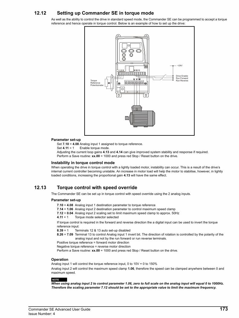
12.12 Setting up Commander SE in torque modeAs well as the ability to control the drive in standard speed mode, the Commander SE can be programmed to accept a torque reference and hence operate in torque control. Below is an example of how to set up the drive:
Parameter set-upSet 7.10 = 4.08 Analog input 1 assigned to torque reference.Set 4.11 = 1 Enable torque mode.Adjusting the current loop gains 4.13 and 4.14 can give improved system stability and response if required.Perform a Save routine: xx.00 = 1000 and press red Stop / Reset button on the drive.
Instability in torque control modeWhen operating the drive in torque control with a lightly loaded motor, instability can occur. This is a result of the drive’s internal current controller becoming unstable. An increase in motor load will help the motor to stabilise, however, in lightly loaded conditions, increasing the proportional gain 4.13 will have the same effect.
12.13 Torque control with speed overrideThe Commander SE can be set up in torque control with speed override using the 2 analog inputs.
Parameter set-up7.10 = 4.08 Analog input 1 destination parameter to torque reference7.14 = 1.06 Analog input 2 destination parameter to control maximum speed clamp7.12 = 0.04 Analog input 2 scaling set to limit maximum speed clamp to approx. 50Hz4.11 = 1 Torque mode selector selectedIf torque control is required in the forward and reverse direction the a digital input can be used to invert the torque reference input:8.39 = 1 Terminals 12 & 13 auto set-up disabled8.26 = 7.09 Terminal 13 to control Analog input 1 invert bit. The direction of rotation is controlled by the polarity of the
analog input and not by the run forward or run reverse terminals.Positive torque reference = forward motor directionNegative torque reference = reverse motor directionPerform a Save routine: xx.00 = 1000 and press red Stop / Reset button on the drive.
OperationAnalog input 1 will control the torque reference input, 0 to 10V = 0 to 150%Analog input 2 will control the maximum speed clamp 1.06, therefore the speed can be clamped anywhere between 0 and maximum speed.
When using analog input 2 to control parameter 1.06, zero to full scale on the analog input will equal 0 to 1000Hz. Therefore the scaling parameter 7.12 should be set to the appropriate value to limit the maximum frequency.
Drive EnableRun ForwardRun ReverseTorque
ReferencePotentiometer
+24V
NOTE
Commander SE Advanced User Guide 173Issue Number: 4

12.14 Torque limitingExample 1When the Commander SE is in torque control and is told to stop by opening the run forward or run reverse terminals, sometimes the motor will carry on turning at low frequency. This is due to inaccuracies in the current measurement circuitry on the drive. This may be seen on unloaded or very lightly loaded motors, but can be overcome by using the following set-up.
Parameter set-up1.22 = 30 Preset speed 2 to the maximum speed the drive will run at (will be 1.22 +20%)1.23 = -750 Preset speed 3 to -750 to give an error between PID main reference and PID reference4.11 = 1 Torque control selected7.10 = 4.08 Analog input 1 destination to torque reference9.04 = 8.03 Logic source 1 to terminal 10 monitor9.05= 1 Logic source 1invert9.06 = 8.04 Logic source 2 to terminal 11 monitor9.07 = 1 Logic source 2 invert9.10 = 14.08 Logic source output to PID enable14.02 = 1.22 Preset speed 2 to PID main reference source14.03 = 1.23 Preset speed 3 to PID reference source14.10 = 0 PID proportional gain to zero14.11 = 0.1 PID integral gain to 0.114.13 = 30 PID high limit to 3014.14 = -30 PID low limit to -3014.15 = 0.1 PID scaling to 0.114.16 = 1.06 PID output to maximum speedPerform a Save routine: xx.00 = 1000 and press red Stop / Reset button on the drive.
OperationWhen the Drive is enabled and told to run via either the run forward or run reverse terminals, the PID loop will be disabled so that the Drive will run in torque control as normal. The maximum output frequency of the Drive is set by the value of preset speed 1 +20%. When either the run forward or run reverse terminals are opened, the PID loop will be enabled, this will create an error between the main PID reference source and the PID reference source. This error will cause the PID output and thus the maximum speed clamp to ramp to zero frequency. This will then clamp the output frequency at zero Hz.
Example 2The following set-up monitors the drive's output current and when this current goes above a set level for a set period of time, stops the drive.
Parameter set-upSet 6.04 = 3 Changes terminal 9, 10 & 11 set-upPerform a Save routine: xx.00 = 1000 and press red Stop / Reset button on the driveSet 8.11 = 1 Terminal 8, digital output invertSet 8.21 = 9.01 Digital output from programmable logic output indicatorSet 8.39 = 1 Terminal 12 & 13 automatic set-up disableSet 8.25 = 6.15 Terminal 12 as Enable/Disable terminalSet 9.04 = 12.01 Programmable logic source 1 from programmable threshold output indicatorSet 9.09 = ?? Programmable logic timer - set to required timeSet 12.03 = 4.01 Programmable threshold source from motor current magnitudeSet 12.04 = ?? Programmable threshold level - set to required levelSet 12.05 = 5 Programmable threshold hysteresis set to 5%Perform a Save routine: xx.00 = 1000 and press red Stop / Reset button on the drive.
Terminal Set-upTerminal 9 = Not Stop (latching)Terminal 10 = Run (latching)Terminal 11 = Forward / ReverseTerminal 12 = EnableConnect terminal 8, digital output to terminal 9, Not Stop input. A normally closed push button switch could be put in series with this connection to allow the drive to be stopped rather than disabled.
174 Commander SE Advanced User GuideIssue Number: 4

Figure 12-3 Terminal Connection Diagram
OperationWith the Enable terminal closed press the normally open Run switch to run the drive, the drive will run up to speed.To stop the drive either
press the normally closed Stop switch in series with the connection between terminals 8 and 9. The motor will stop under the control of selected stopping mode and then disable
or open the enable switch to terminal 12. The drives output will be inhibited and the motor will coast to a stop.
When the drive is running and the motor current (4.01) is below the threshold level set in 12.04, the drive will run normally. If the motor current increases above this threshold, then the programmable threshold indicator (12.01) will be set to a 1. This will cause the programmable logic timer (9.09) to start timing. Once this time has elapsed the programmable logic indicator (9.01) will cause the digital output to change state. Because the digital output is feeding into the Not Stop terminal, the drive will Stop.If during the programmable logic timer period the motor current falls back below the programmable threshold level, the drive will continue to run normally.The programmable logic timer (9.09) and the programmable logic threshold level (12.04) can be set as required for the particular application.
12.15 Keypad / Terminal ControlThe set-up below allows the drive to be started and stopped from the drives terminals and for the speed of the motor to be controlled by the keypads up and down buttons.
This set-up will only function with V01.08.00 (and later) Commander SE User Interface software.
Parameter set-upSet 1.22 = 0.4 Preset speed reference 2 to 0.4Set 1.23 = 0.1 Preset speed reference 3 to 0.1Set 9.04 = 6.30 Prog. logic function 1 source parameter to run forwardSet 9.05 = 1 Prog. logic function source 1 invert invertedSet 9.06 = 6.32 Prog. logic function 2 source parameter to run reverseSet 9.07 = 1 Prog. logic function source 2 invert invertedSet 9.10 = 12.10 Prog. logic function destination to variable selector selectSet 12.08 = 1.22 Variable selector source 1 to preset speed 1Set 12.09 = 1.23 Variable selector source 2 to preset speed 2Set 12.11 = 1.14 Variable selector destination to reference selectPerform a Save routine: xx.00 = 1000 and press red Stop / Reset button on the drive.
OperationWhen either the run forward or run reverse terminal is closed allowing the drive to run, keypad mode is selected. This allows the drive’s speed to be increased or decreased via the drive’s up and down buttons on the drive’s keypad. The drive can also be stopped or started via the drive’s keypad. If the drive is running and either the run forward or run reverse terminal is opened, the drive will stop as keypad mode is deselected and terminal mode selected.
Digital output
Not Stop
Run
Enable
+24V
8
9
10
11
12
13
14
Forward / Reverse
NOTE
Commander SE Advanced User Guide 175Issue Number: 4

12.16 Timed Digital OutputThe following set-up can be used to get a delay of up to 33 minutes between the drive being told to run and the digital output switching.
1.22 = 11 Preset speed 2 to 118.21 = 12.01 Digital output (terminal 8) controlled by threshold reached indicator9.04 = 10.02 Programmable logic source to drive running indicator9.10 = 14.08 Programmable logic destination to PID enable12.03 = 14.01 Programmable threshold to PID controller output12.04 = 90 Programmable threshold level set to 90%14.03 = 1.22 PID reference source to preset speed 214.10 = 0 PID proportional gain to 014.11 = 0.05 PID integral gain to 0.0514.14 = 0 PID low limit to 0Perform a Save routine: xx.00 = 1000 and press red Stop / Reset button on drive
OperationWhen the drive is told to run the PID loop is enabled. An error is created and this error integrates the PID controller output. When the PID controller output reaches the programmable threshold level, the digital output is switched. When the drive is told to stop, the PID loop is disable which resets the PID loop error so that when the drive is told to run again, the timing starts from zero.This set-up with the PID reference source set to 1 and the integral gain set to 0.05 gives 2000 seconds for 100% in the threshold level. With the above set-up of 90% in the threshold level, the digital output will switch in a time of 1800 seconds (30 minutes). The threshold can obviously be adjusted to give the required time, if a time of 20 minutes is required:
20 x 60 = 1200 seconds1200 / 2000 = 0.6 x 100 = 60
Therefore set parameter 12.04 to 60% to get a time of 20 minutes.
12.17 Variable Select Set-up (Selecting two levels of Voltage boost)The Variable Selector allows a second value to be switched to one parameter on a particular operation of the drive. This can be used to change the value of a parameter or change the mode of operation of the drive. Preset speed parameters can be used as the Variable Selector source parameters. The Variable Selector destination parameter can only be programmed to unprotected parameters. It cannot be programmed to protected, source or destination parameters.
Example 1Two different levels of boost can be set, a low level during the starting of a motor and a higher level during the stopping of a motor.
Set-up5.14 = 2 Voltage mode select to fixed boost mode9.04 = 1.11 Programmable logic function 1 source parameter to reference enable indicator9.10 = 12.10 Programmable logic function destination to Variable Selector select12.08 = 1.21 Variable selector source 1 to preset speed 112.09 = 1.22 Variable selector source 2 to preset speed 212.11 = 5.15 Variable selector destination to voltage boost1.21 = 8.0 High level of boost. Set as appropriate1.22 = 2.0 Low level of boost. Set as appropriatePerform a Save routine: xx.00 = 1000 and press red Stop / Reset button on the drive
OperationThe programmable logic function monitors parameter 1.11 reference enabled indicator. When the drive is told to run, the output of the programmable logic switches the variable selector select parameter so that the low level of boost is programmed to parameter 5.15. When the drive is told to stop, the output of the programmable logic switches the variable selector select parameter so that the high level of boost is programmed to parameter 5.15. The level of boost applied can be adjusted by changing the values of parameters 1.21 and 1.22.
176 Commander SE Advanced User GuideIssue Number: 4

Example 2The variable selector can also be used to select between two modes of operation of an unprotected parameter of the drive e.g. parameter 1.14 reference select
Set-up1.22 = 0.4 Preset speed 2 to 0.41.23 = 0.l Preset speed 3 to 0.19.04 = 6.30 Logic source 1 to run forward9.05 = 1 Logic source 1 inverted9.06 = 6.32 Logic source 2 to run reverse9.07 = 1 Logic source 2 inverted9.10 = 12.10 Logic destination to variable selector select12.08 = 1.22 Variable selector source 1 to preset speed 112.09 = 1.23 Variable selector source 2 to preset speed 212.11 = 1.14 Variable selector output to reference selectPerform a Save routine: xx.00 = 1000 and press red Stop / Reset button on the drive
OperationWhen either the run forward or run reverse terminal is closed allowing the drive to run, keypad mode is selected. This allows the drive’s speed to be increased or decreased via the drive’s up and down buttons on the drive’s keypad. The drive can also be stop or started via the drive’s keypad. If the drive is running and either the run forward or run reverse terminal is opened, the drive will stop as keypad mode is de-selected and terminal mode selected.
Parameter 1.14 was only unprotected in V01.08.00 software.
To change between other different modes of parameter 1.14 or another parameter, change the values of parameters 1.21 and 1.22
0.0 Mode 0 A1.A20.1 Mode 1 A1.Pr0.2 Mode 2 A2.Pr0.3 Mode 3 Pr0.4 Mode 4 PAd0.5 Mode 5 Prc
12.18 Analog input trimThe following set-up allows analog input 1 to be used as the main speed reference and analog input 2 as an offset trim of the main reference.
Example 11.21 = 500 Preset speed 1 to 500. This will give an error between PID reference source and PID feedback7.10 = 0 Analog input 1 destination to zero 7.14 = 0 Analog input 2 destination to zero14.02 = 7.01 PID main reference source to analog input 1 percentage14.03 = 7.02 PID reference source to analog input 2 percentage14.04 = 1.21 PID feedback source to preset speed 114.08 = 1 PID enabled14.11 = 0 PID integral gain to zero14.13 = 25 PID high limit to 25 14.14 = -25 PID low limit to -2514.16 = 1.36 PID output to analog reference 1Perform a Save routine: xx.00 = 1000 and press red Stop / Reset button on the drive
OperationWith the above set-up, analog reference 1 can be used as normal to control the speed of the motor. Analog reference 2 canbe used to increase or decrease (trim) this speed around analog reference 1. With this set-up the trim will be approx. ±12.5Hzaround analog reference 1. Parameter 14.13 and 14.14 can be increased or decreased to give larger or smaller trim value.One problem with the above set-up is if maximum trim is set on analog reference 2 with zero speed reference on analog ref-erence 1, the drive will run at maximum trim speed and not go to zero speed. If the motor is required to go to zero speed withzero reference, the following set-up should be used.
NOTE
Commander SE Advanced User Guide 177Issue Number: 4
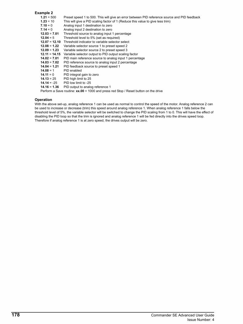
Example 21.21 = 500 Preset speed 1 to 500. This will give an error between PID reference source and PID feedback1.23 = 10 This will give a PID scaling factor of 1 (Reduce this value to give less trim)7.10 = 0 Analog input 1 destination to zero7.14 = 0 Analog input 2 destination to zero12.03 = 7.01 Threshold source to analog input 1 percentage12.04 = 5 Threshold level to 5% (set as required)12.07 = 12.10 Threshold indicator to variable selector select12.08 = 1.22 Variable selector source 1 to preset speed 212.09 = 1.23 Variable selector source 2 to preset speed 312.11 = 14.15 Variable selector output to PID output scaling factor14.02 = 7.01 PID main reference source to analog input 1 percentage14.03 = 7.02 PID reference source to analog input 2 percentage14.04 = 1.21 PID feedback source to preset speed 114.08 = 1 PID enabled14.11 = 0 PID integral gain to zero14.13 = 25 PID high limit to 25 14.14 = -25 PID low limit to -2514.16 = 1.36 PID output to analog reference 1Perform a Save routine: xx.00 = 1000 and press red Stop / Reset button on the drive
OperationWith the above set-up, analog reference 1 can be used as normal to control the speed of the motor. Analog reference 2 can be used to increase or decrease (trim) this speed around analog reference 1. When analog reference 1 falls below the threshold level of 5%, the variable selector will be switched to change the PID scaling from 1 to 0. This will have the effect of disabling the PID loop so that the trim is ignored and analog reference 1 will be fed directly into the drives speed loop. Therefore if analog reference 1 is at zero speed, the drives output will be zero.
178 Commander SE Advanced User GuideIssue Number: 4

12.19 Programmable threshold set-upThe Commander SE drive software supports a software controllable numerical comparator. This comparator can be used to detect when an internal or external signal exceeds a user set point threshold. The threshold comparator also provides a hysteresis band to prevent erratic operation at or near the threshold point.This example shows how the programmable threshold can be set up to switch on an integrated motor cooling fan, when the drive speed falls below 50%.
Parameter set-up12.03 = 5.01 Threshold detector source parameter assigned to motor frequency.12.04 = 50% Threshold level as a percentage of maximum reference.8.27 = 12.01 Programmable relay source parameter assigned to “threshold exceeded” signal.Set threshold detector hysteresis band (12.05) if required. This will define the band within which no change will occur on the output.Perform a Save routine: xx.00 = 1000 and press red Stop / Reset button on drive.
U V W
1 2 3
1615
SPEED REFERENCE
Motor ventilation ON
Motor ventilation OFF
100%
50%
0%240V AC
Fan Supply
Contactor
Commander SE Advanced User Guide 179Issue Number: 4
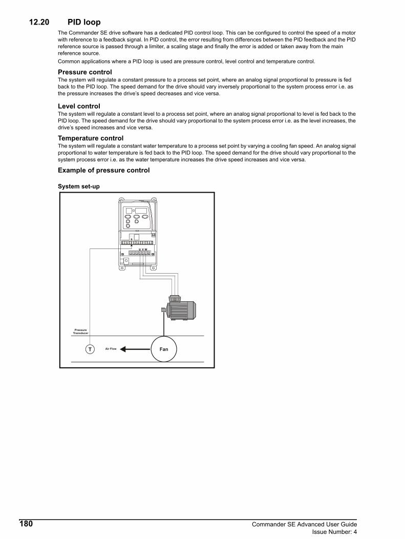
12.20 PID loopThe Commander SE drive software has a dedicated PID control loop. This can be configured to control the speed of a motor with reference to a feedback signal. In PID control, the error resulting from differences between the PID feedback and the PID reference source is passed through a limiter, a scaling stage and finally the error is added or taken away from the main reference source.Common applications where a PID loop is used are pressure control, level control and temperature control.
Pressure controlThe system will regulate a constant pressure to a process set point, where an analog signal proportional to pressure is fed back to the PID loop. The speed demand for the drive should vary inversely proportional to the system process error i.e. as the pressure increases the drive’s speed decreases and vice versa.
Level control The system will regulate a constant level to a process set point, where an analog signal proportional to level is fed back to the PID loop. The speed demand for the drive should vary proportional to the system process error i.e. as the level increases, the drive’s speed increases and vice versa.
Temperature controlThe system will regulate a constant water temperature to a process set point by varying a cooling fan speed. An analog signal proportional to water temperature is fed back to the PID loop. The speed demand for the drive should vary proportional to the system process error i.e. as the water temperature increases the drive speed increases and vice versa.
Example of pressure control
System set-up
T
PressureTransducer
Air Flow Fan
180 Commander SE Advanced User GuideIssue Number: 4

Drive set-up
Parameter set-up Firstly, establish the actual speed in Hz that is needed to maintain the required pressure for the system. This should be set by the potentiometer or terminal 2 or by the value in preset speed 1.22. This will be the speed set point.
On terminal 2, 0 - 10V = 0 - 100% Parameter 1.22, 0 - 1000 = 0 - 100%
Set 7.10 = 0.00 Analog input 1 is not required to be assigned to a destination.Set 7.14 = 0.00 Analog input 2 is not required to be assigned to a destination.Set 7.11 for the appropriate feedback range.Set 14.03 = 7.01 or 1.22 dependant on the chosen speed and set point.Set 14.04 = 7.02 PID feedback reference assigned to feedback signal from current transducer.Set 14.08 = 1 Enable PID.Set 14.16 = 1.36 PID output assigned to control the final speed reference, which will increase or decrease
automatically depending on the errordetected and therefore maintain a constant pressure.It may be necessary to adjust the internal PID gains 14.10, 14.11 and 14.12 to improve system stability and response.Perform a Save routine: xx.00 = 1000 and press red Stop / Reset button on drive.
With this set-up, as the feedback signal increases the speed of the motor will decrease and vice versa.For level control and temperature control, as the feedback signal increases the speed of the motor should increase. To achieve this, set 14.06 = 1 and 14.05 = 1 to invert the feedback signal.
Terminal 2 7.01
+10V
0V
1.22
14.03
X-1
0
1
1.36
X-1
1 0
14.04
7.02
Terminal 5
Mode7.11
T
Set point PID loop
Feedback
Speedreference
NOTE
Commander SE Advanced User Guide 181Issue Number: 4

12.21 2 x Latching Run Forward Inputs
Set-up for 2 x Latching Run Forward Inputs
V01.08.00 software or later must be used for this set-up. It will not work with earlier versions.
The following set-up gives two momentary latching Run Forward inputs with two different speeds set by the analog inputs.
Set-up6.04 = 1Perform a Save routine: xx.00 = 1000 and press red Stop / Reset button on the drive1.10 = 1 Allow negative digital references1.22 = 0.2 Preset 2 to 0.21.23 = 0.1 Preset 3 to 0.17.13 = 1 Analog input 2 invert9.04 = 1.12 Logic function source 1 to reverse selected bit9.10 = 12.10 Logic function destination to variable select selector bit12.08 = 1.23 Variable selector source 1 to preset 312.09 = 1.22 Variable selector source 2 to preset 212.11 = 1.14 Variable selector destination to reference selectorPerform a Save routine: xx.00 = 1000 and press red Stop / Reset button on the drive
Terminal set-up
OperationWhen the Run Forward 1 terminal is closed momentarily the drive will run forward at the speed requested by analog input 1When the Run Forward 2 terminal is closed momentarily the drive will run forward at the speed requested by analog input 2
NOTE
2
7
8
9
10
11
+24V
/Stop
Run Forward 1
Run Forward 2
6
5
4
3
1
Analog input 2
Analog input 1
0V
+10V
mA Input
182 Commander SE Advanced User GuideIssue Number: 4

12.22 Jog CommandExample 1The following set-up allows the jog function to run from 'rd' and by the use of only one normally open push button switch. Also, when the jog is released, the drive will go back to 'rd' rather than run up to the set speed reference. This set-up only allows running and jogging in the forward direction.
Parameter set up6.04 = 4 Terminals 9, 10 & 11 as user programmable terminalsPerform a Save routine: xx.00 = 1000 and press red Stop / Reset button on the drive8.22 = 6.39 Terminal 9 as a Not Stop terminal8.39 = 1 Disable auto set-up of terminals 12 & 138.25 = 0 No destination for terminal 129.04 = 8.05 Terminal 12 monitor to programmable logic source 19.05 = 1 Programmable logic source invert9.09 = 0.1 Programmable logic source delay to 0.1 seconds9.10 = 6.40 Programmable logic destination to “enable latching run inputs”.Perform a Save routine: xx.00 = 1000 and press red Stop / Reset button on the drive
OperationWhen the normally open Run Forward switch on terminal 10 is momentarily closed, the drive will enable and run in the forward direction to the set speed controlled by the potentiometer.
When the normally closed Not Stop switch on terminal 9 is momentarily opened, the drive will ramp to a stop and disable.
When the drive is in the 'rd' condition and the normally open Jog switch is closed, the drive will run up to jog speed set by parameter 15. When the Jog switch is opened, the drive will ramp down and return to the 'rd' condition.
When the drive is running at speed controlled by the speed potentiometer and then the jog switch is closed, the drive will ramp down and run at the jog speed. When the jog switch is opened, the drive will ramp down and return to the 'rd' condition.
Terminal Diagram
4
7
9
10
11
12
13
14
0V
+24V
Not Stop
Run Forward
Run Reverse
Latches Enable
Jog
+24V
3
2
1
+10V
Local speed ref. input
0V
Relay 1N/O x 2
Relay 1+24V coil
Jog
Commander SE Advanced User Guide 183Issue Number: 4

Example 2The following set-up allows the jog function to run from 'rd' and by the use of only one normally open push button switch.Also, when the jog is released, the drive will go back to 'rd' rather then run up to the set speed reference. This set up also allows running and jogging in forward and reverse.
Parameter set up6.04 = 4 Terminals 9, 10 & 11 as user programmable terminalsPerform a Save routine: xx.00 = 1000 and press red Stop / Reset button on the drive8.22 = 6.39 Terminal 9 as a Not Stop terminal8.23 = 6.34 Terminal 10 as a Run terminal8.24 = 6.33 Terminal 11 as a Forward / Reverse terminal8.39 = 1 Disable auto set-up of terminals 12 & 138.25 = 0 No destination for terminal 129.04 = 8.05 Terminal 12 monitor to programmable logic source 19.05 = 1 Programmable logic source invert9.09 = 0.1 Programmable logic source delay to 0.1 seconds9.10 = 6.40 Programmable logic destination to “enable latching run inputs”.Perform a Save routine: xx.00 = 1000 and press red Stop / Reset button on the drive
OperationWhen the normally open Run switch on terminal 10 is momentarily closed, the drive will enable and run in the forward direction to the set speed controlled by the potentiometer.
When the normally closed Not Stop switch on terminal 9 is momentarily opened, the drive will ramp to a stop and disable.
When the drive is in the 'rd' condition and the normally open Jog switch is closed, the drive will run up to jog speed set by parameter 15. When the Jog switch is opened, the drive will ramp down and return to the 'rd' condition.
When the drive is running at speed controlled by the speed potentiometer and then the jog switch is closed, the drive will ramp down and run at the jog speed. When the jog switch is then opened, the drive will ramp down and return to the 'rd' condition.
The direction of running and jogging is controlled by the switch on terminal 11. If the switch is open, the drive will run and jog in the forward direction. If the switch is closed, the drive will run and jog in the reverse direction.
Terminal Diagram
4
7
9
10
11
12
13
14
0V
+24V
Not Stop
Run
Forward / Reverse
Latches Enable
Jog
+24V
3
2
1
+10V
Local speed ref. input
0V
Relay 1N/O x 2
Relay 1+24V coil
Jog
184 Commander SE Advanced User GuideIssue Number: 4

12.23 Flux BrakingThe following set-up can be used to dissipate more energy in a motor while decelerating and therefore it has the possibility of eliminating the need for a braking resistor. This may be especially useful on Commander SE size 1 which does not have the capability of dynamic braking.
Set-upThis set-up can be used on a standard 50Hz motor.
1.21 = 40.5 Preset speed 1 to 40.5Hz (customer adjustable for different speed motors - 60Hz etc.)1.22 = 20.0 Preset speed 2 to 20.0Hz (customer adjustable in conjunction with PID integral gain to set time for the
motor rated frequency to change from 40Hz to 50Hz and vice versa)2.04 = 0 Fast ramp stopping mode selected12.03 = 5.01 Threshold source from motor frequency12.04 = 70 Threshold level set at 70% (customer adjustable, sets motor frequency at which V/f curve changes. Setting lower than 70% may cause OV or OI.AC tripping of the drive)12.06 = 1 Threshold output inverted12.07 = 14.06 Threshold destination to PID feedback invert14.02 = 1.21 PID main reference source from preset speed 114.04 = 1.22 PID feedback source from preset speed 214.08 = 1 PID enabled14.10 = 0 PID P gain set to 014.11 = 1 PID I gain to 1.014.13 = 1.0 PID high limit to 1.014.14 = 0.0 PID low limit to 0.014.16 = 5.06 PID destination to motor rated frequencyPerform a Save routine: xx.00 = 1000 and press red Stop / Reset button on the drive
OperationWhen the drive is in the 'rd' condition, the motor rated frequency (parameter 39) will be set to 50.0 which is the standard setting for a 50Hz motor. When the drive is given a run command and the motor frequency is increased, the correct V/f profile will be followed until the motor frequency reaches the programmable threshold % value set in parameter 12.04 (70% in this example). At this point, the motor rated frequency will be decreased to 40Hz (set by parameter 1.21). The rate at which the motor rated frequency decreases can be adjusted by changing the value in preset speed 2 and/or the PID integral gain value. The V/f characteristic will be slightly incorrect for the motor as the frequency is increased from 40 to 50Hz but this should not cause any problems with performance, etc.
When the drive is given a stop command and the motor frequency is reduced, the motor volts will remain high until the programmable threshold level is reached and then the motor volts will reduce back to the standard V/f characteristic.
The motor volts remaining high for the first part of the deceleration ramp overfluxes the motor. This has the effect of increasing the losses within the motor and therefore reduces the amount of energy being transferred back to the drive. Increasing the losses in the motor will cause the motor temperature to increase slightly.
In experiments with a set inertia, implementing this set-up has allowed the deceleration ramp to be decreased by approximately 30% without OV trips occurring.
The following plots show the standard V/f curve and the flux braking V/f curve during the acceleration and deceleration ramps.
V/f Curve during acceleration
0
50
100
150
200
250
300
0 10 20 30 40 50
Ouput Frequency
Motor Volts - Fluxbraking
Motor Volts -Standard Set-Up
Mot
or V
olts
Commander SE Advanced User Guide 185Issue Number: 4

V/f curve during deceleration
12.24 Variable TrimIn some applications, it may be necessary to achieve the same % trim across a wide range of set point frequencies. The following set-up allows approximately 10% trim regardless of the set-point frequency.
Parameter set-up1.21 = 500 Preset speed 1 to 5007.10 = 0 Analog input 1 destination set to 07.14 = 0 Analog input 2 destination set to 012.08 = 1.03 Variable selector source 1 to Pre-ramp reference12.11 = 14.13 Variable selector output to PID high limit14.02 = 7.01 PID main reference source to analog input 1 monitor14.03 = 7.02 PID reference source to analog input 2 monitor14.04 = 1.21 PID feedback source to preset speed 114.11 = 0 PID integral gain to 014.14 = 0 PID low limit to 014.15 = 0.18 PID scaling set to 0.1814.16 = 1.36 PID output to analog reference 114.18 = 1 PID symmetrical limit selector set14.08 = 1 PID enabledPerform a Save routine: xx.00 = 1000 and press red Stop / Reset button on the drive
Parameter 14.15 can be increased or decreased slightly to give greater or less than 10 % trim.
The above set-up will give a approximately 10% trim on 50 or 60Hz set-ups. If the maximum speed is set greater than this, the value of parameter 14.15 should be reduce accordingly to give the required % trim.
OperationThe set speed of the drive is controlled by a potentiometer on terminal 2, analog input 1.
The trim is controlled by a current signal on terminal 5, analog input 2. When this signal gives a value of 50.0% in parameter 7.02, analog input 2 monitor, no trim is provided. When this value is 0.0, the maximum value of trim is subtracted from the output frequency. When this value is 100.0, the maximum value of trim is added from the output frequency.
The PID loop is used to either add or subtract this trim value to or from the main reference provided by analog input 1.
To keep the same % trim regardless of the speed of the motor, the drive uses the pre-ramp reference to write to the PID high and low limits. This value along with the PID scaling allows the % of trim to remain the same as the main speed reference is changed.
ExampleIf the main speed reference is 10Hz, the trim will be 10Hz +/-10%. Therefore the trim will be from 9Hz to 11Hz.
If the main speed reference is 40Hz, the trim will be 40Hz +/-10%. Therefore the trim will be from 36Hz to 44Hz.
0
50
100
150
200
250
300
01020304050
Output Frequency
Motor Volts - FluxBraking
Motor Volts -Standard Set-Up
Mot
or v
olts
186 Commander SE Advanced User GuideIssue Number: 4

12.25 Quickey CompatibilityDue to different versions of Drive user interface software, it is possible to get a compatibility issue when using the Quickey to clone parameter set-ups between drives. This compatibility issue will cause the drive to trip on C.dat.
The following table gives the compatibility between different versions of drive user interface software:
NO: The Quickey cannot clone between these two versions of drive softwareYES: The Quickey can clone between these two versions of drive software
*V02.00.04 is only used on Commander SE Size 5.
12.26 Controlling the Commander SE via the Universal KeypadExample 1This set up uses the UP and DOWN buttons on the Universal Keypad to control the speed of the motor: UP to increase the speed and DOWN to decrease the speed.The Enable/Stop/Start/Forward/Reverse control is from the drives terminals and not the Universal Keypad buttons.Keypad top line display set up
Keypad bottom line display set up
Keypad buttons set up
Drive parameters set up
Perform a save routine: xx.00 = 1000 and press the red Stop / Reset button on the drive.Perform a Universal Keypad save routine: 99.00 = 1000 and press the red Stop / Reset button on the keypad.
Software V01.02.01 V01.03.00 V01.05.00 V01.07.00 V01.08.00 V01.09.01 V01.10.00 V02.00.01 V02.00.04*
V01.02.01 NO NO NO NO NO NO NO NO
V01.03.00 NO YES NO NO NO NO NO NO
V01.05.00 NO YES NO NO NO NO NO NO
V01.07.00 NO NO NO YES YES YES YES YES
V01.08.00 NO NO NO YES YES YES YES YES
V01.09.01 NO NO NO YES YES YES YES YES
V01.10.00 NO NO NO YES YES YES YES YES
V02.00.01 NO NO NO YES YES YES YES YES
V02.00.04* NO NO NO YES YES YES YES YES
Parameter Description Value99.16 HMI 2 source address 1199.17 HMI 2 source parameter 1.2199.20 HMI 2 text Speed reference99.41 HMI 2 increment 10099.42 HMI 2 upper limit 50,00099.43 HMI 2 lower limit 0
Parameter Description Value99.09 HMI 1 source address 1199.10 HMI 1 source parameter 4.0199.13 HMI 1 text Motor I
Parameter Description Value99.05 Keypad control buttons Disable
Parameter Description Value00.05 Speed reference selector Pr6.43 Control word enable 0
Commander SE Advanced User Guide 187Issue Number: 4

Example 2This set up uses the UP and DOWN buttons on the Universal Keypad to control the speed of the motor: UP to increase the speed and DOWN to decrease the speed.The Stop/Start/Forward/Reverse control is from the Universal Keypad Stop/Start/Forward/Reverse buttons and not the drive’s terminals.
Keypad top line display set up
Keypad bottom line display set up
Keypad buttons set up
Drive parameters set up
Perform a drive save routine: xx.00 = 1000 and press the Stop / Reset button on the drive.Perform a Universal Keypad save routine: 99.00 = 1000 and press the red Stop / Reset button on the keypad.
Example 3This set up uses the drive’s motor potentiometer function with the Universal Keypads F1 button used to increase the motor speed and F3 button to decrease the motor speed. The Stop/Start/Forward/Reverse control is from the drive’s terminals.
The macro buttons F1 and F3 are latching so they need to be pressed twice to clear i.e. pressing F1 starts the increase in speed, a second press of F1 stops the increase in speed.
Keypad top line display set up
Keypad bottom line display set up
Parameter Description Value99.16 HMI 2 source address 1199.17 HMI 2 source parameter 1.2199.20 HMI 2 text Speed reference99.41 HMI 2 increment 10099.42 HMI 2 upper limit 50,00099.43 HMI 2 lower limit 0
Parameter Description Value99.09 HMI 1 source address 1199.10 HMI 1 source parameter 4.0199.13 HMI 1 text Motor I99.05 Control Keys Enable
Parameter Description Value99.05 Keypad control buttons Enable
Parameter Description Value00.05 Speed reference selector Pr6.41 Control word mask 116.43 Control word enable 1
Parameter Description Value99.16 HMI 2 source address 1199.17 HMI 2 source parameter 1.2199.20 HMI 2 text Speed reference99.41 HMI 2 increment 10099.42 HMI 2 upper limit 50,00099.43 HMI 2 lower limit 0
Parameter Description Value99.09 HMI 1 source address 1199.10 HMI 1 source parameter 4.0199.13 HMI 1 text Motor I
NOTE
188 Commander SE Advanced User GuideIssue Number: 4
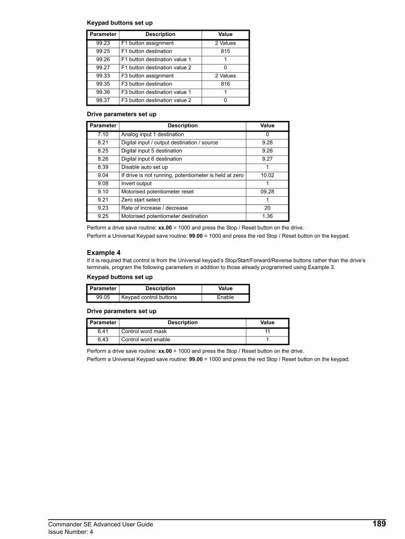
Keypad buttons set up
Drive parameters set up
Perform a drive save routine: xx.00 = 1000 and press the Stop / Reset button on the drive.Perform a Universal Keypad save routine: 99.00 = 1000 and press the red Stop / Reset button on the keypad.
Example 4If it is required that control is from the Universal keypad’s Stop/Start/Forward/Reverse buttons rather than the drive’s terminals, program the following parameters in addition to those already programmed using Example 3.
Keypad buttons set up
Drive parameters set up
Perform a drive save routine: xx.00 = 1000 and press the Stop / Reset button on the drive.Perform a Universal Keypad save routine: 99.00 = 1000 and press the red Stop / Reset button on the keypad.
Parameter Description Value99.23 F1 button assignment 2 Values99.25 F1 button destination 81599.26 F1 button destination value 1 199.27 F1 button destination value 2 099.33 F3 button assignment 2 Values99.35 F3 button destination 81699.36 F3 button destination value 1 199.37 F3 button destination value 2 0
Parameter Description Value7.10 Analog input 1 destination 08.21 Digital input / output destination / source 9.288.25 Digital input 5 destination 9.268.26 Digital input 6 destination 9.278.39 Disable auto set up 19.04 If drive is not running, potentiometer is held at zero 10.029.08 Invert output 19.10 Motorised potentiometer reset 09.289.21 Zero start select 19.23 Rate of increase / decrease 209.25 Motorised potentiometer destination 1.36
Parameter Description Value99.05 Keypad control buttons Enable
Parameter Description Value6.41 Control word mask 116.43 Control word enable 1
Commander SE Advanced User Guide 189Issue Number: 4

12.27 Open loop vector or fixed boost modesCommander SE is a voltage source inverter in which the motor voltage is controlled to correctly flux the motor. The Commander SE can be set-up in one of two modes to control the voltage to frequency profile to be applied to the motor:
Open loop vector mode or fixed boost mode.
Open loop vector modeThe drive uses the programmed motor map parameters and the motor stator resistance measured during an autotune to calculate the voltage to frequency profile to apply to the motor.
Motor Map Parameters:06 Motor rated current07 Motor rated speed08 motor rated voltage09 Motor power factor
If the motor is not a standard 50 or 60Hz motor, the following parameters should also be set correctly before an autotune is carried out:
02 Maximum speed39 Rated frequency40 Number of motor poles
To maintain optimum performance, if any motor map parameters or components are changed within the system that may effect the parameters measured during an autotune i.e. motor cabling, motor, motor line chokes, another autotune should be performed.
Fixed boost modeThe drive uses the programmed motor map parameters and the programmed percentage boost level to calculate the voltage to frequency profile to apply to the motor. An autotune is not required as the stator resistance is not used to calculate the voltage to frequency profile. The motor map parameters should still be entered correctly.
Open loop vector or fixed boostAt low motor speeds, the motors stator resistance increases and therefore the stator voltage drop of the motor increases. To try to maintain a constant flux within the motor, the motor terminal voltage must be increased at low motor speed to compensate for the increase in stator resistance. This is particularly important in high starting torque applications where the stator voltage drop will be greater due to the increase in stator current. Open loop vector automatically increases the terminal voltage at low motor frequency and applies a V/f profile dependant on the values measured during an autotune. Fixed boost increases the terminal voltage and applies a voltage/frequency profile dependant on the % value of boost.The main advantage of using open loop vector mode over fixed boost mode is that the motor will be correctly fluxed over all motor frequencies below base speed. In fixed boost mode, it is very difficult to set the correct amount of boost and it is very easy to overflux the motor, which can cause the motor to stall and/or overheat. Normally the boost level is set by the method of trial and error.Saying that, it may be possible to set the boost level to a value to get increased performance or better starting torque at low speed because the applied motor terminal voltage is slightly greater than that applied when in open loop vector mode.
Stator ResistanceIt is possible to manually change the measured stator resistance value, parameter 5.17. Increasing this value slightly will increase the amount of volts applied to the motor at low frequency. This will have the effect of increasing the starting torque. Increasing the stator resistance by too much can cause the motor to be overfluxed and cause the drive to trip on over current.
If a high starting torque is not required e.g. fan or pump application, the performance at low speed is not important so open loop vector or fixed boost mode with very low % boost or even 0% boost can be used.In both open loop vector mode and fixed boost mode, the motor voltage is increased above the normal V/f curve up to half motor rated frequency. Above this, the V/f curve follows the standard V/f profile.
190 Commander SE Advanced User GuideIssue Number: 4

Motor Map ParametersIt is important that before an autotune is carried out, all the motor map parameters are set correctly. The motor map parameters are:
Parameter 06 - motor rated currentThe motor rated current is the 100% full load current for the motor.
Parameter 07 - motor rated speedThe motor rated speed is the slip speed at 100% full load current.
Parameter 08 - motor rated voltageThis is the rated voltage of the motor at rated frequency.
Parameter 09 - motor power factorThis is the power factor of the motor when at 100% full load current.
In addition to these, parameters 02 - maximum speed, parameter 39 - motor rated frequency and parameter 40 - number of motor poles, should be set correctly if the motor isn't a standard 50/60Hz motor.
Non-rotating AutotuneWhen the drive carries out an autotune, its main aim is to measure the motor stator resistance. The drive then uses this measurement to calculate the correct voltage to frequency profile to apply to the motor. The drive also measures the system voltage offset which is the voltage drop within the drive and between the drive and the motor. The drive than uses this figure to compensate for the volt drop to make sure it is applying the correct voltage to the motor.
Rotating autotuneAs well as measuring the motors stator resistance and system voltage offset, it measures the rated magnetising current and the total system leakage inductance. The drive uses these figures to calculate the full load power factor for the motor. This is then used to calculate the correct active current for the motor. The advantage of having a correctly calculated power factor is that a more accurate slip compensation (if enabled) will be applied to the motor.
After an autotune has been carried out, the measured parameters are automatically saved in the drive.
Power factorIt is also important that the correct power factor is entered into the drives motor map. This is so the drive knows the correct magnetising and active current for the motor. Various parameters and values are calculated from these parameters so that if these values are incorrect, these parameters will be incorrect.
The power factor is the angle between the active current and the current magnitude at 100% full load motor rated current.
Outputfrequency
Motorvoltage
Motor ratedfrequency
Motor ratedfrequency / 2
Motor ratedvoltage / 2
Motor ratedvoltage
StandardV/f profile
Open loop vector orfixed boost increase themotor voltage at lowfrequency
Commander SE Advanced User Guide 191Issue Number: 4
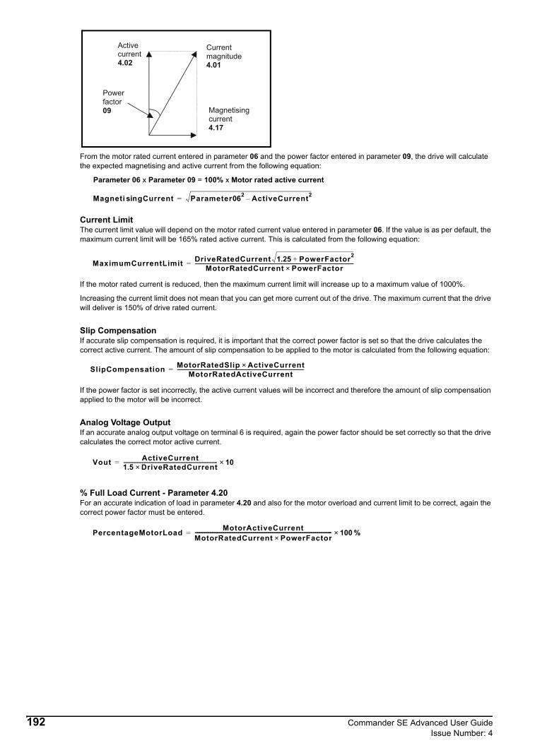
From the motor rated current entered in parameter 06 and the power factor entered in parameter 09, the drive will calculate the expected magnetising and active current from the following equation:
Parameter 06 x Parameter 09 = 100% x Motor rated active current
Current LimitThe current limit value will depend on the motor rated current value entered in parameter 06. If the value is as per default, the maximum current limit will be 165% rated active current. This is calculated from the following equation:
If the motor rated current is reduced, then the maximum current limit will increase up to a maximum value of 1000%.
Increasing the current limit does not mean that you can get more current out of the drive. The maximum current that the drive will deliver is 150% of drive rated current.
Slip CompensationIf accurate slip compensation is required, it is important that the correct power factor is set so that the drive calculates the correct active current. The amount of slip compensation to be applied to the motor is calculated from the following equation:
If the power factor is set incorrectly, the active current values will be incorrect and therefore the amount of slip compensation applied to the motor will be incorrect.
Analog Voltage OutputIf an accurate analog output voltage on terminal 6 is required, again the power factor should be set correctly so that the drive calculates the correct motor active current.
% Full Load Current - Parameter 4.20For an accurate indication of load in parameter 4.20 and also for the motor overload and current limit to be correct, again the correct power factor must be entered.
%
Magnetisingcurrent4.17
Activecurrent4.02
Currentmagnitude4.01
Powerfactor09
Magneti gCurrentsin Parameter062 ActiveCurrent2–=
MaximumCurrentLimit DriveRatedCurrent 1.25 PowerFactor2+MotorRatedCurrent PowerFactor×
-------------------------------------------------------------------------------------------------------------------------------=
SlipCompensation MotorRatedSlip ActiveCurrent×MotorRatedActiveCurrent
-----------------------------------------------------------------------------------------------------=
Vout ActiveCurrent1.5 DriveRatedCurrent×--------------------------------------------------------------------------- 10×=
PercentageMotorLoad MotorActiveCurrentMotorRatedCurrent PowerFactor×------------------------------------------------------------------------- 100×=
192 Commander SE Advanced User GuideIssue Number: 4

12.28 Ramp ModesFor Commander SE, the are 3 ramp modes - parameter 2.04:• Fast ramp• Standard ramp with normal motor voltage• Standard ramp with high motor voltageDepending on the setting of parameter 6.01, the drive will enter one of the above ramp modes when the run forward, run reverse, run or not stop terminals are opened.
Fast RampParameter 2.04 = 0
The deceleration ramp will fall at the programmed deceleration rate in parameter 02 (subject to current limits programmed).
From the default parameter set-up, the deceleration ramp is set to 10 seconds per 100Hz. Therefore from 50Hz, the deceleration ramp will be 5 seconds.
Depending on the type of load and inertia, the DC bus may increase because of regenerated energy flowing back into the drive. If the deceleration ramp is too fast and the regenerated energy is too great to be absorbed by the drive, the drive may trip on over voltage - OV. To overcome this problem, a braking resistor should be fitted to the drive to absorb the regenerated energy.
Although the DC may rise during the deceleration ramp, the motor voltage will stay constant at the set motor rated voltage.
Standard Ramp with Normal Motor VoltageParameter 2.04 = 1
The drive will try to stop the motor at the deceleration rate programmed in parameter 02. The drive may increase the deceleration ramp time automatically to try and prevent the drive tripping on over voltage - OV.
If the DC bus increases above the set upper standard ramp voltage level - parameter 2.08, the drives software will suspend the deceleration ramp until the DC bus voltage falls below the lower standard ramp voltage level, the drives software will then continue the deceleration ramp. Again if the DC bus increases above the set upper standard ramp voltage level, the drives software will suspend the deceleration ramp until the DC bus voltage falls below the lower standard ramp voltage level, the drives software will then continue the deceleration ramp. This process will continue until the DC bus voltage does not increase above the set upper standard ramp voltage level, so that the ramp can continue at its programmed value.
Although the DC may rise during the deceleration ramp, the motor voltage will stay constant at the set motor rated voltage.
50Hz
5 seconds
DC bus voltage
Stop command
Motorfrequency
Time
50Hz
5 seconds
DC bus voltage
Stop command
Ramp timeextended
Upper standard rampvoltage - parameter 2.08
Time
Motorfrequency
Commander SE Advanced User Guide 193Issue Number: 4
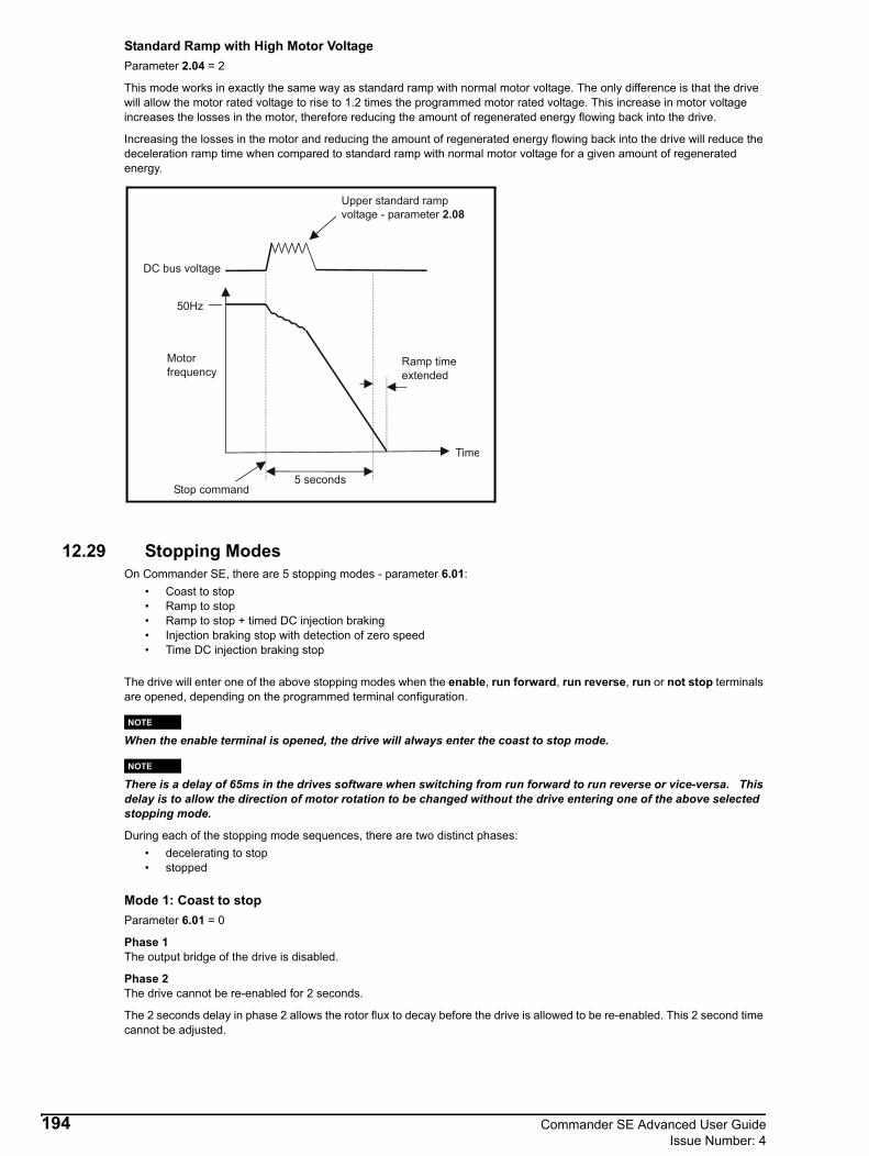
Standard Ramp with High Motor VoltageParameter 2.04 = 2
This mode works in exactly the same way as standard ramp with normal motor voltage. The only difference is that the drive will allow the motor rated voltage to rise to 1.2 times the programmed motor rated voltage. This increase in motor voltage increases the losses in the motor, therefore reducing the amount of regenerated energy flowing back into the drive.
Increasing the losses in the motor and reducing the amount of regenerated energy flowing back into the drive will reduce the deceleration ramp time when compared to standard ramp with normal motor voltage for a given amount of regenerated energy.
12.29 Stopping ModesOn Commander SE, there are 5 stopping modes - parameter 6.01:
• Coast to stop• Ramp to stop• Ramp to stop + timed DC injection braking• Injection braking stop with detection of zero speed• Time DC injection braking stop
The drive will enter one of the above stopping modes when the enable, run forward, run reverse, run or not stop terminals are opened, depending on the programmed terminal configuration.
When the enable terminal is opened, the drive will always enter the coast to stop mode.
There is a delay of 65ms in the drives software when switching from run forward to run reverse or vice-versa. This delay is to allow the direction of motor rotation to be changed without the drive entering one of the above selected stopping mode.
During each of the stopping mode sequences, there are two distinct phases:• decelerating to stop• stopped
Mode 1: Coast to stopParameter 6.01 = 0
Phase 1The output bridge of the drive is disabled.
Phase 2The drive cannot be re-enabled for 2 seconds.
The 2 seconds delay in phase 2 allows the rotor flux to decay before the drive is allowed to be re-enabled. This 2 second time cannot be adjusted.
50Hz
5 seconds
DC bus voltage
Stop command
Ramp timeextended
Upper standard rampvoltage - parameter 2.08
Motorfrequency
Time
NOTE
NOTE
194 Commander SE Advanced User GuideIssue Number: 4

Mode 2: Ramp to stopParameter 6.01 = 1 (default)
Phase 1The drive will ramp down to zero frequency under the control of the selected ramp mode (parameter 2.04) in the time set by the deceleration rate.
Phase 2The drive will wait for 1 second with the output bridge enabled and then it will disable.
Mode 3: Ramp to stop + timed DC injection brakingParameter 6.01 = 2
Phase 1The drive will ramp down to zero frequency under the control of the selected ramp mode (parameter 2.04) in the time set by the deceleration rate.
Phase 2Then DC current is injected into the motor at a level specified by parameter 6.06 and for a time specified by parameter 6.07.
Normally when this mode is used, phase 1 decelerates the motor to a stop and phase 2 locks the rotor shaft. This can be useful when trying to fully stop an inertia load i.e. fan.
Mode 4: Injection braking stop with detection of zero speedParameter 6.01 = 3
Phase 1A low frequency current at 5Hz is injected into the motor at the level programmed by parameter 6.06, this will have the effect of slowing down the motor. When the motor reaches 5Hz, the software goes into phase 2.
When the drive injects the low frequency current at 5Hz, it detects that regen current is flowing. When the motor reaches 5Hz, this regen current stops and therefore the drive knows that the motor is at 5Hz.
Phase 2DC current is injected into the motor at a level specified by parameter 6.06 and for a time specified by parameter 6.07.
The drive automatically senses low speed so therefore it adjusts the injection time to suit the application. If the injection current level is too small, the drive will not sense low speed and it will sit at 5Hz (normally 50-60% is required in parameter 6.06).
Mode 5: Time DC injection braking stopParameter 6.01 = 4
Phase 1DC current is injected into the motor at a level specified by parameter 6.06 and for a time specified by parameter 6.07.
Phase 2DC current is injected into the motor at a level specified by parameter 6.06 for 1 second.
The minimum total DC injection braking time is 1 second for phase 1 and 1 second for phase 2. Therefore the minimum DC injection braking time is 2 seconds.
Normally, the combination of the DC injection braking current level and injection braking time during phase 1 is used to stop the motor from rotating. Then the 1 second DC injection braking in phase 2 is used to lock the motor shaft.
If the DC injection braking current level is set to a high level in parameter 6.06, the less time is required in parameter 6.07 to stop the motor. If the DC injection braking current is set to a low level, the more time is required in parameter 6.07 to stop the motor.
Once Mode 3 - Injection braking stop with detection of zero speed or Mode 4 - Time DC injection braking stop modes have begun, the drive must go through the 'ready' state before being restarted either by stopping, tripping or being disabled.
NOTE
Commander SE Advanced User Guide 195Issue Number: 4