inventory of repair and strengthening methods with - upcommons
TRANSCRIPT
Inventory of Repair and Strengthening Methods with Iron and Steel
Erasmus Mundus Programme
ADVANCED MASTERS IN STRUCTURAL ANALYSIS OF MONUMENTS AND HISTORICAL CONSTRUCTIONS
1
DECLARATION
Name: Samiye Mircan Kaya
Email: [email protected]; [email protected]
Title of the
Msc Dissertation:
Inventory of Repair and Strengthening Methods with Iron and Steel
Supervisor(s): Professor Climent Molins
Year: 2009
I hereby declare that all information in this document has been obtained and presented in accordance with
academic rules and ethical conduct. I also declare that, as required by these rules and conduct, I have fully cited
and referenced all material and results that are not original to this work.
I hereby declare that the Msc Consortium responsible for the Advanced Masters in Structural Analysis of
Monuments and Historical Constructions is allowed to store and make available electronically the present
MSc Dissertation.
University: Technical University of Catalonia
Date: July 12,2009
Signature: ___________________________
Inventory of Repair and Strengthening Methods with Iron and Steel
Erasmus Mundus Programme
ADVANCED MASTERS IN STRUCTURAL ANALYSIS OF MONUMENTS AND HISTORICAL CONSTRUCTIONS
2

Inventory of Repair and Strengthening Methods with Iron and Steel
Erasmus Mundus Programme
ADVANCED MASTERS IN STRUCTURAL ANALYSIS OF MONUMENTS AND HISTORICAL CONSTRUCTIONS
3
“A structural engineer, looking at a Gothic cathedral, will see, not a massive array of nave piers, but
the skeletal structure formed by the centre-lines of those piers; not a thick vault, but a thin doubly-
curved sheet spanning between the mathematical centre-lines of the ribs.”
Jacques Heyman
Starting from my early childhood years, learning, discovering new things and challenges have always
been the driving force for my personal development. It was one of my dreams to study in Europe after
graduating the high school which turned out to be a dream which would not be realized. In years, with
the projects I got involved, I was able to strengthen my connections not only with Europe but with
other parts of the world more and more, yet studying and living in a country , experiencing the real life,
traditions and culture is totally different then visiting for certain durations.
I had to suspend and change many things in my life to be the part of this study but I will never regret. It
was really a big challenge after all the achievements in my life to show the willingness to take this
―exam‖- starting from zero point, accepting the apprenticeship which is the unique antidote to cure and
improve the personality. It will stand as a hinge in the middle of my life representing many things,
connecting my past with my future as a strong device furnishing my personality with necessary
resistance and tolerance I shall need for the rest of my life.
It was a unique experience to stay at a studio apartment in Padova in an absolute isolation mood and
concentrating on one specific issue which was a real luxurious situation in my life as a person who had
to deal with many things at a time, as woman and as a mother. It was a great amusement to walk
along the streets of Barcelona, exploring the architectural texture of the city in between the sessions of
searching and typing the report. It was a great experience to see and compare the different cultures,
traditions, habits of different societies, nations. I will never forget how I was deeply affected when I
saw the people from 7 to 77 years old were dancing and singing perfectly and naturally during Feria
de Abril in Barcelona. I will never forget how people still was discussing vehemently in the piazzas of
Padova on top of a stool as a person from a country where come-togethers are treated suspiciously. I
have definitely acquired a knowledge which could only be conceived by living.
In the light of all these feelings, I would like to dedicate this ―period – SAHC advanced master study‖ to
all the achievements of human beings, to all the marvelous persons inspired us with their creations, to
fearlessness, to intelligence, cognition, supremacy of knowledge and enlightenment,
And to my dearest brother Mahomet Emin Ay-my role model who passed away when he was only 26
shortly after his graduation as a civil engineer.

Inventory of Repair and Strengthening Methods with Iron and Steel
Erasmus Mundus Programme
ADVANCED MASTERS IN STRUCTURAL ANALYSIS OF MONUMENTS AND HISTORICAL CONSTRUCTIONS
4

Inventory of Repair and Strengthening Methods with Iron and Steel
Erasmus Mundus Programme
ADVANCED MASTERS IN STRUCTURAL ANALYSIS OF MONUMENTS AND HISTORICAL CONSTRUCTIONS
5
ACKNOWLEDGEMENTS
I would like to acknowledge the support I got from my supervisor Professor Climent Molins, who
guided me with his comments throughout the dissertation period.
I would like to express my deepst gratitude to the Msc Consortium and the Erasmus Mundus
Programme for giving me the opportunity to participate in this very enriching study and the financial
support.
As indicated as the motivation and objective of this study on SAHC ‗s web site, Europe is a world
leader in the generation of knowledge, methodology and technology applicable to the conservation
and restoration of the architectural heritage. The large investment made during the last years lead to
significant advances in experimental and numerical techniques applied to the conservation of
architectural heritage structures and I was proud to take the challenge of being the part of this
perfectly organized study which combined the diversity of expertise at leading European universities
in the field, offering education oriented to a multidisciplinary understanding of structural conservation
through the involvement of experts from complementary fields (engineers, architects, materials
scientists and others). The programme fulfilled its promise by facing us top level structural analysis
knowledge in a research oriented environment, with close cooperation with the industry and a focus on
problem solving.
I would like to sincerely thank to all the friends I made in the university of Padova and Barcelona
(Ahmed, Murat, Thomas, Peter, Emmanuel, Tasos, Justin, Jiri, Yee, John, Patricia, Logan, Dechen,
Ziba and Vanesse).
My sepcial thanks to Elisa Trovo who was always available to help with her smiling face.
I would also like to thank to my friends in FIP INDUSTRIALE S.p.A(Paolo Baldo, Gabriella Castellano,
Schuster Astrid) who supported me throughout my study, for their incomparable friendship and
hospitality.
I cannot pass without mentioning the patience of my dearest children Setenay and Oğuz for their
encouraging manners towards me and their courage of practicing and experiencing life without their
mother. I am grateful to my daughter Setenay and her friend Didem for their help to organize the text
to fit in the template.
After all these years of dealing with many different types of engineering projects, it is not an
exageration to say that it is this study which gave me a unique tool of conceving an engineering
structure as a whole with its idiosyncratics.
Thank you......

Inventory of Repair and Strengthening Methods with Iron and Steel
Erasmus Mundus Programme
ADVANCED MASTERS IN STRUCTURAL ANALYSIS OF MONUMENTS AND HISTORICAL CONSTRUCTIONS
6
Inventory of Repair and Strengthening Methods with Iron and Steel
Erasmus Mundus Programme
ADVANCED MASTERS IN STRUCTURAL ANALYSIS OF MONUMENTS AND HISTORICAL CONSTRUCTIONS
7
ABSTRACT
This study aimed at producing a report (inventory) on stabilization / repair / strengthening materials,
methods and technologies used for the structural restoration of structures including cast iron, wrought
iron and steel members. A detailed literature survey was carried out by reading as much document as
possible using different database including UPC library and after all the courses studied throughout
this advanced master study it may be concluded that regardless of the technique decided to be
applied in a restoration project, it is very important that any repair or strengthening must be based on
a correct diagnosis of the problem by determining the real cause of the observed defects, and if the
cause is still active by eliminating it. Otherwise the repairs will be short-lived. There is a parallel in the
field of medicine: any treatment must be preceded by a correct diagnosis.
Masonry is one of the oldest construction material and tracing back the use of masonry will take us to
the history of the civilization. It is not an exaggerate to say that masonry represents civilization. From
the first ruble walls of the Stone Age to contemporary brick veneer systems, it is masonry the
architects and engineers turn to when performance, solidity, aesthetics are sought the evolution of
which is parallel to the one of civilization.
The problem of conserving and structural restoration of architectural heritage and is complex involving
different challenges. It is is multidisciplinary task carried out with the involvement of different
competencies like architects, engineers, arcehologiests and historians. It is very important to follow a
methodology which includes survey, diagnosis, saftey evaluation and the selection of the correct and
effective intervention technique fitting best with the strengthening requirements for the specific building
with respect to it‘s original conception and the historic value.
This is a difficult task because of the complexity of the geometry of historic monuments, the variable
and often unpredictable characteristics of original materials, the different building techniques, the
absence of knowledge on the existing damages occured throughout their life due to several reasons,
and the lack of applicable codes. In addition, restrictions in the inspection and the removal of
specimens in buildings of historical value, as well as the high costs involved in inspection and
diagnosis, often result in limited information about the internal structural system or the properties of
existing materials. Without a thorough understanding of the mechanisms of decay and deterioration
conservation skills can not be increased to prolong the life of cultural property for future generations.
consideration of these aspects is not simple and calls for qualified persons capable of combining
advanced knowledge in the field with engineering reasoning, as well as a careful, time-consuming
approach
Although there are a lot of materials and intervention techniques available for structural restorations
recent philosophy underlying restoration recommends to prefer prefer techniques that are fullfilling the
criterias like minimum intervention, compatibility, durability, reversibility or substitutability. In principle
Inventory of Repair and Strengthening Methods with Iron and Steel
Erasmus Mundus Programme
ADVANCED MASTERS IN STRUCTURAL ANALYSIS OF MONUMENTS AND HISTORICAL CONSTRUCTIONS
8
this philosophy is correct, but one should not forget that any decission may not always be error-free
and it is therefore unwise to exclude the possibility of exploiting better techniques and materials if and
when they are developed. conservation requirements .
In chapters 5, 6 and 7 of this report, different repair/strengthening techniques using iron and steel are
discussed according to the possible causes of damages of the structures. Post-tensioning,
strengthening with ant-seismic devices like shape memory alloy devices and shock transmittion units
in combination with other strengthening techniques are discussed as innovative techniques.
Application examples can be found in chapter six of the report which explains in detail the techniques.

Inventory of Repair and Strengthening Methods with Iron and Steel
Erasmus Mundus Programme
ADVANCED MASTERS IN STRUCTURAL ANALYSIS OF MONUMENTS AND HISTORICAL CONSTRUCTIONS
9
RESUMEN
Este estudio tiene como objetivo elaborar un informe (inventario) sobre la estabilización / reparación /
el fortalecimiento de los materiales, métodos y tecnologías utilizadas para la restauración estructural
de las estructuras incluidas hierro fundido, hierro forjado y acero miembros. Un detallado estudio de la
literatura fue llevada a cabo por la lectura tanto como sea posible el documento base de datos
utilizando diferentes bibliotecas UPC y después de todos los cursos estudiados a lo largo de este
maestro de avanzada estudio se puede concluir que independientemente de la técnica decidió que se
aplicarán en un proyecto de restauración, se es muy importante que cualquier reparación o
fortalecimiento debe basarse en un diagnóstico correcto del problema mediante la determinación de
la verdadera causa de los defectos observados, y si la causa sigue activa, por su eliminación. De lo
contrario, la reparación será de corta duración. Hay un paralelo en el campo de la medicina: cualquier
tratamiento debe ser precedido por un diagnóstico correcto.
Albañilería es uno de los más antiguos materiales de construcción y el rastreo de nuevo el uso de
albañilería nos llevará a la historia de la civilización. No es exagerar decir una mampostería que
representa la civilización. Desde el primer rublo paredes de la Edad de Piedra hasta la chapa de los
sistemas de ladrillo, es de mampostería los arquitectos e ingenieros a su vez, cuando el rendimiento,
la solidez, la estética se busca la evolución de la que es paralela a la una de la civilización.
El problema de la conservación y la restauración estructural del patrimonio arquitectónico y es
complejo que participen diferentes desafíos. Es tarea multidisciplinaria se llevó a cabo con la
participación de las diferentes competencias, como arquitectos, ingenieros, arqueólogos e
historiadores. Es muy importante seguir una metodología que incluye el estudio, diagnóstico,
evaluación de la seguridad y la selección de la correcta y eficaz de intervención técnica de montaje
con los mejores requisitos para el fortalecimiento de la construcción con respecto a su concepción
original y el valor histórico.
Esta es una tarea difícil debido a la complejidad de la geometría de los monumentos históricos, la
variable y, a menudo impredecibles características de materiales originales, las distintas técnicas de
construcción, la ausencia de conocimientos sobre la actual se produjeron daños a lo largo de su vida
debido a varias razones, y la la falta de códigos aplicables. Además, las restricciones en la inspección
y la eliminación de los especímenes en los edificios de valor histórico, así como los altos costos
implicados en la inspección y el diagnóstico, a menudo como resultado información limitada acerca de
la estructura interna del sistema o las propiedades de los materiales existentes. Sin una profunda
comprensión de los mecanismos de la decadencia y el deterioro de conservación de las
competencias no puede ser aumentado a prolongar la vida de los bienes culturales para las
generaciones futuras.
Inventory of Repair and Strengthening Methods with Iron and Steel
Erasmus Mundus Programme
ADVANCED MASTERS IN STRUCTURAL ANALYSIS OF MONUMENTS AND HISTORICAL CONSTRUCTIONS
10
consideración de estos aspectos no es sencillo y requiere personal cualificado capaz de combinar un
conocimiento avanzado en el campo de la ingeniería con el razonamiento, así como una cuidadosa,
el tiempo que consume enfoque. Aunque hay una gran cantidad de materiales y técnicas de
intervención disponibles para restauraciones estructurales reciente restauración de la filosofía
subyacente a preferir prefiero recomienda técnicas que se cumplen los criterios de intervención, como
mínimo, la compatibilidad, duración, reversibilidad o de sustitución. En principio, esta filosofía es
correcta, pero no hay que olvidar que cualquier decisión puede no ser siempre libre de errores y, por
tanto, es prudente descartar la posibilidad de explotar las mejores técnicas y materiales, siempre y
cuando sean desarrollados. los requisitos de conservación.
En los capítulos 5,6 y 7 de este informe, los diferentes reparación / el fortalecimiento de las técnicas
que utilizan el hierro y el acero se discuten en función de las posibles causas de los daños de las
estructuras. Post-tensado, con el fortalecimiento de hormiga sismológicas dispositivos como
dispositivos de memoria de forma de aleación y las unidades de choque de transmisión en
combinación con otras técnicas de refuerzo como se discuten las técnicas innovadoras. Ejemplos de
aplicación se pueden encontrar en el capítulo seis del informe, que explica en detalle las técnicas.
Inventory of Repair and Strengthening Methods with Iron and Steel
Erasmus Mundus Programme
ADVANCED MASTERS IN STRUCTURAL ANALYSIS OF MONUMENTS AND HISTORICAL CONSTRUCTIONS
11
RIASSUNTO
Questo studio mira a produrre una relazione (inventario) sulla stabilizzazione / riparazione /
rafforzamento dei materiali, i metodi e le tecnologie utilizzate per il restauro strutturale di strutture tra
cui ghisa, ferro battuto e acciaio membri. Una dettagliata indagine letteratura è stata effettuata con la
lettura di un documento di più come possibile utilizzando diversi database tra cui UPC biblioteca e
dopo che tutti i corsi di studi avanzati in questo studio master si può concludere che,
indipendentemente dalla tecnica ha deciso di essere applicata in un progetto di restauro, è è molto
importante che ogni riparazione o il rafforzamento deve essere basata su una corretta diagnosi del
problema da determinare la vera causa del osservati difetti, e se la causa è ancora attivo, eliminando
esso. In caso contrario, la riparazione sarà di breve durata. C'è un parallelo nel campo della medicina:
ogni trattamento deve essere preceduto da una corretta diagnosi.
Muratura è uno dei più antichi materiali da costruzione e per rintracciare l'utilizzo di muratura ci porterà
alla storia della civiltà. Non si tratta di un esagerare a dire che in muratura rappresenta civiltà. Dal
primo rublo mura di pietra per la contemporanea mattone impiallacciato sistemi, è in muratura gli
architetti e gli ingegneri a sua volta, quando le prestazioni, solidità, estetica sono chiesta l'evoluzione
di cui è parallela a quella della civiltà.
Il problema della conservazione e restauro strutturale del patrimonio architettonico è complessa e
coinvolge diverse sfide. E 'compito multidisciplinare è effettuata con il coinvolgimento di diverse
competenze, come architetti, ingegneri, archeologi e storici. E 'molto importante seguire una
metodologia che comprende indagine, la diagnosi, la valutazione della sicurezza e la selezione del
corretto ed efficace intervento tecnica di montaggio in modo ottimale con il rafforzamento requisiti
specifici per l'edilizia con il rispetto alla sua originale concezione e il valore storico.
Questo è un compito difficile a causa della complessità della geometria dei monumenti storici, la
variabile e spesso imprevedibile caratteristiche dei materiali originali, le diverse tecniche di
costruzione, mancanza di conoscenze sulle esistenti danni verificatisi nel corso della loro vita a causa
di vari motivi, e la mancanza di codici applicabili. Inoltre, le restrizioni durante l'ispezione e la
rimozione di esemplari, in edifici di valore storico, così come i costi elevati in materia di ispezione e
diagnosi, spesso sfociano in numero limitato di informazioni sulla struttura interna del sistema o le
proprietà dei materiali esistenti. Senza una profonda comprensione dei meccanismi di degrado e
deterioramento tecniche di conservazione non può essere aumentata a prolungare la vita dei beni
culturali per le generazioni future. considerazione di questi aspetti non è semplice e richiede persone
qualificate in grado di coniugare conoscenze avanzate nel campo di ingegneria ragionamento, così
come una attenta, in termini di tempo approccio.
Anche se ci sono un sacco di materiali e tecniche di intervento a disposizione per gli interventi
strutturali recenti restauri filosofia che sottende il restauro raccomanda a preferire preferiscono
tecniche che sono rispondenti ai criteri di intervento, come minimo, la compatibilità, la durata, la
reversibilità o la sostituibilità. In linea di principio, questa filosofia è corretta, ma non bisogna

Inventory of Repair and Strengthening Methods with Iron and Steel
Erasmus Mundus Programme
ADVANCED MASTERS IN STRUCTURAL ANALYSIS OF MONUMENTS AND HISTORICAL CONSTRUCTIONS
12
dimenticare che qualsiasi decisione non può essere sempre esente da errori ed è quindi sconsigliabile
per escludere la possibilità di sfruttare meglio le tecniche e materiali se e quando si sono sviluppate.
esigenze di conservazione.
Nei capitoli 5,6 e 7 della presente relazione, diversi riparazione / rafforzamento utilizzando tecniche di
ferro e acciaio sono discusse secondo le possibili cause dei danni delle strutture. Post-tensionamento,
rafforzando con ant-sismica dispositivi in lega a memoria di forma come i dispositivi di trasmissione e
shock unità in combinazione con altre tecniche di rafforzamento sono discussi come tecniche
innovative. Esempi di applicazione possono essere trovate nel capitolo sei della relazione, che spiega
in dettaglio le tecniche.
Inventory of Repair and Strengthening Methods with Iron and Steel
Erasmus Mundus Programme
ADVANCED MASTERS IN STRUCTURAL ANALYSIS OF MONUMENTS AND HISTORICAL CONSTRUCTIONS
13
TABLE OF CONTENTS Page
ABSTRACT . . . . . . . . . . . . . . . . . . . . . . . . . . . . . . . . . . . . . . . . . . . . . 7
RESUMEN. . . . . . . . . . . . . . . . . . . . . . . . . . . . . . . . . . . . . . . . . . . . . . .9
RIASSUNTO. . . . . . . . . . . . . . . . . . . . . . . . . . . . . . . . . . . . . . . . . . . . .11
TABEL OF CONTENTS. . . . . . . . . . . . . . . . . . . . . . . . . . . . . . . . . . . ..13
LIST OF FIGURES. . . . . . . . . . . . . . . . . . . . . . . . . . . . . . . . . . . . . . . . 19
CHAPTER 1 . . . . . . . . . . . . . . . . . . . . . . . . . . . . . . . . . . . . . . . . . . . . .27
INTRODUCTION . . . . . . . . . . . . . . . . . . . . . . . . . . . . . . . . . . . . . . . . . 27
1.1.1 The aim. . . . . . . . . . . . . . . . . . . . . . . . . . . . . . . . . . . . . . . . . . . . .27
1.1.2 The search. . . . . . . . . . . . . . . . . . . . . . . . . . . . . . . . . . . . . . . . . . 27
1.1.3 The Methodolgy. . . . . . . . . . . . . . . . . . . . . . . . . . . . . . . . . . . . . . 27
CHAPTER 2. . . . . . . . . . . . . . . . . . . . . . . . . . . . . . . . . . . . . . . . . . . . . .29
THE PRINCIPALS OF CONSERVATION. . . . . . . . . . . . . . . . . . . . . . .29
2.1 General. . . . . . . . . . . . . . . . . . . . . . . . . . . . . . . . . . . . . . . . . . . . . . 29
2.1 Conservation Methodology. . . . . . . . . . . . . . . . . . . . . . . . . . . . . . . 29
2.3 Concepts of Intervention. . . . . . . . . . . . . . . . . . . . . . . . . . . . . . . . . 30
2.4 Inventories and Documentation. . . . . . . . . . . . . . . . . . . . . . . . . . . .31
2.4.1 Documentation. . . . . . . . . . . . . . . . . . . . . . . . . . . . . . . . . .32
2.5 Interventions. . . . . . . . . . . . . . . . . . . . . . . . . . . . . . . . . . . . . . . . . . 32
2.6 Prevention Deterioration. . . . . . . . . . . . . . . . . . . . . . . . . . . . . . . . . 33
2.7 Preservation. . . . . . . . . . . . . . . . . . . . . . . . . . . . . . . . . . . . . . . . . .33
2.8 Consolidation. . . . . . . . . . . . . . . . . . . . . . . . . . . . . . . . . . . . . . . . . 33

Inventory of Repair and Strengthening Methods with Iron and Steel
Erasmus Mundus Programme
ADVANCED MASTERS IN STRUCTURAL ANALYSIS OF MONUMENTS AND HISTORICAL CONSTRUCTIONS
14
2.9 Restoration. . . . . . . . . . . . . . . . . . . . . . . . . . . . . . . . . . . . . . . . . . . . . . . 34
2.10 Rehabilitation. . . . . . . . . . . . . . . . . . . . . . . . . . . . . . . . . . . . . . . . . . . . .34
2.11 Reproduction. . . . . . . . . . . . . . . . . . . . . . . . . . . . . . . . . . . . . . . . . . . . .35
2.12 Reconstruction. . . . . . . . . . . . . . . . . . . . . . . . . . . . . . . . . . . . . . . . . . . .35
2.13 ICOMOS Recommendations. . . . . . . . . . . . . . . . . . . . . . . . . . . . . . . . . 35
2.13.1 Principles. . . . . . . . . . . . . . . . . . . . . . . . . . . . . . . . . . . . . . . . . 35
2.13.2 Guidelines. . . . . . . . . . . . . . . . . . . . . . . . . . . . . . . . . . . . . . . . .36
CHAPTER 3. . . . . . . . . . . . . . . . . . . . . . . . . . . . . . . . . . . . . . . . . . . . . . . . . . 39
HISTORIC PERSPECTIVE FOR MASONARY STRUCTURES. . . . . . . . . . .39
3.1 Historical Background. . . . . . . . . . . . . . . . . . . . . . . . . . . . . . . . . . . . . . . .39
3.1.1 Evolution of Structural Shapes. . . . . . . . . . . . . . . . . . . . . . . . . . 40
3.2 Structural Aspects of Historic Buildings. . . . . . . . . . . . . . . . . . . . . . . . . . .43
3.3 Materials Used in Historic Buildings. . . . . . . . . . . . . . . . . . . . . . . . . . . . .50
3.4 Causes of Decay in Materials and Structure. . . . . . . . . . . . . . . . . . . . . . .51
CHAPTER 4 . . . . . . . . . . . . . . . . . . . . . . . . . . . . . . . . . . . . . . . . . . . . . . . . . .53
EVALUATION & ASSESMENT of EXISTING MASONARY BUILDINGS. .53
4.1 Investigation. . . . . . . . . . . . . . . . . . . . . . . . . . . . . . . . . . . . . . . . . . . . . . .53
4.2 Decision Making. . . . . . . . . . . . . . . . . . . . . . . . . . . . . . . . . . . . . . . . . . . .53
CHAPTER 5. . . . . . . . . . . . . . . . . . . . . . . . . . . . . . . . . . . . . . . . . . . . . . . . . .55
CONSERVATION AND STRUCTURAL STRENGTHENING OF MASONRY
STRUCTURES. . . . . . . . . . . . . . . . . . . . . . . . . . . . . . . . . . . . . . . . . . . . . . . . 55
5.1 General. . . . . . . . . . . . . . . . . . . . . . . . . . . . . . . . . . . . . . . . . . . . . . . . . . . 55

Inventory of Repair and Strengthening Methods with Iron and Steel
Erasmus Mundus Programme
ADVANCED MASTERS IN STRUCTURAL ANALYSIS OF MONUMENTS AND HISTORICAL CONSTRUCTIONS
15
5.2 Stabilization & Repair & Strengthening Techniques with Iron and Steel. . . . . 56
5.2.1 Structural Assesment & Structural Appraisal. . . . . . . . . . . . . . . . . . . 58
5.2.2 Causes of Damage. . . . . . . . . . . . . . . . . . . . . . . . . . . . . . . . . . . . . . .61
5.2.3. Repair and Strengthening of Walls and Piers. . . . . . . . . . . . . . . . . . 62
5.2.4 Structural Restoration of Arches ,Vaults and Domes . . . . . . . . . . . . 65
5.2.5 Bed joint Reinforcement Technique. . . . . . . . . . . . . . . . . . . . . . . . . . 79
5.2.6 Seismic Retrofitting of Unreinforced Masonry with Metallic or Different
Material Tie-Rods. . . . . . . . . . . . . . . . . . . . . . . . . . . . . . . . . . . . . . . . . . . .89
5.2.7 Details for Repair and Strengthening of Stone and Brick Masonry
Houses . . . . . . . . . . . . . . . . . . . . . . . . . . . . . . . . . . . . . . . . . . . . . . . . . . . . 97
5.2.8 Strengthening of Foundations. . . . . . . . . . . . . . . . . . . . . . . . . . . . . . .123
5.2.9 Masonry Cladding to Iron and Steel Framed Buildings. . . . . . . . . . . 129
5.3 Innovative Techniques. . . . . . . . . . . . . . . . . . . . . . . . . . . . . . . . . . . . . . . . . . 131
5.3.1 General. . . . . . . . . . . . . . . . . . . . . . . . . . . . . . . . . . . . . . . . . . . . . . . .131
5.3.2 Prestressing & Post Tensioning. . . . . . . . . . . . . . . . . . . . . . . . . . . . . 131
5.3.3 History of Prestressing & Post-Tensioning. . . . . . . . . . . . . . . . . . . . . 132
5.3.4 Strengthening of Historic Buildings with Post-Tensioning. . . . . . . . . .137
5.3.5 Use of Shape Memory Alloy Devices and Shozk Transmitters for Seismic
Protection of Monument. . . . . . . . . . . . . . . . . . . . . . . . . . . . . . . . . . . . . . . .141
5.3.6 Shoring. . . . . . . . . . . . . . . . . . . . . . . . . . . . . . . . . . . . . . . . . . . . . . . . 144
5.3.7 Drilling. . . . . . . . . . . . . . . . . . . . . . . . . . . . . . . . . . . . . . . . . . . . . . . . . 146
5.3.8 Use of Stainless Steel and Titanium in Restorarion. . . . . . . . . . . . . . . . . . . .148
Inventory of Repair and Strengthening Methods with Iron and Steel
Erasmus Mundus Programme
ADVANCED MASTERS IN STRUCTURAL ANALYSIS OF MONUMENTS AND HISTORICAL CONSTRUCTIONS
16
CHAPTER 6 . . . . . . . . . . . . . . . . . . . . . . . . . . . . . . . . . . . . . . . . . . . . . . . . . . . . . . 151
CASE STUDIES. . . . . . . . . . . . . . . . . . . . . . . . . . . . . . . . . . . . . . . . . . . . . . . . . . . .151
6.1 Problems Related to Repair and Strengthening of Historic Masonry Buildings in
Historic Centers of Umbria. . . . . . . . . . . . . . . . . . . . . . . . . . . . . . . . . . . . . . . . . . . .151
6.1.1 Introduction. . . . . . . . . . . . . . . . . . . . . . . . . . . . . . . . . . . . . . . . . . . . . 151
6.1.2. Failure Mechanisms of Repaired and Unrepaired Buildings . . . . . . .152
6.1.2.1 Isolated buildings (Montesanto) . . . . . . . . . . . . . . . . . . . . . . .152
6.1.2.2 Row houses (Roccanolfi) . . . . . . . . . . . . . . . . . . . . . . . . . . . 152
6.1.3 Structural and Material Compatibility Problems. . . . . . . . . . . . . . . . . . 153
6.1.4.Critical Comments on Wall and pier jacketing. . . . . . . . . . . . . . . . . . . 153
6.1.5 Concluding Remarks. . . . . . . . . . . . . . . . . . . . . . . . . . . . . . . . . . . . . . .154
6.2. French Pantheon- The Causes of Structural Disorders of Soufflot‘s
Pantheon in Paris . . . . . . . . . . . . . . . . . . . . . . . . . . . . . . . . . . . . . . . . . . . . . . . . . . 155
6.2.1 General. . . . . . . . . . . . . . . . . . . . . . . . . . . . . . . . . . . . . . . . . . . . . . . . .155
6.2.2 The Causes of the Main Disorders. . . . . . . . . . . . . . . . . . . . . . . . . . . .157
6.2.3 Concluding Remarks. . . . . . . . . . . . . . . . . . . . . . . . . . . . . . . . . . . . . . .158
6.3 Minarets at Risk in Afghanistan. . . . . . . . . . . . . . . . . . . . . . . . . . . . . . . . . . . . . 159
6.3.1 Introduction. . . . . . . . . . . . . . . . . . . . . . . . . . . . . . . . . . . . . . . . . . . . . .159
6.3.2 Emergency Securing of the Minaret Five in Herat . . . . . . . . . . . . . . . .160
6.3.3 Minaret of Jam. . . . . . . . . . . . . . . . . . . . . . . . . . . . . . . . . . . . . . . . . . . 161
6.4. Technologies for the prestressing rings of the leaning tower of Pisa. . . . . . . . 162
6.4.1.General. . . . . . . . . . . . . . . . . . . . . . . . . . . . . . . . . . . . . . . . . . . . . . . . .162
6.4.2. Interventions required the use of post-tensioning. . . . . . . . . . . . . . . . 162
6.4.3 Temporary Circumferential Prestressing of the First Loggia. . . . . . . . 164
6.4.4 The Concrete Counterweight-holder Beam. . . . . . . . . . . . . . . . . . . . . 165

Inventory of Repair and Strengthening Methods with Iron and Steel
Erasmus Mundus Programme
ADVANCED MASTERS IN STRUCTURAL ANALYSIS OF MONUMENTS AND HISTORICAL CONSTRUCTIONS
17
6.4.5 Circumferential Prestressing at the First Loggia with a 4mm Dia.
Stainless Steel Wire. . . . . . . . . . . . . . . . . . . . . . . . . . . . . . . . . . . . . . . . . . . .166
6.4.6 The Catino Bottom Restorign and its Connection to the Tower . . . . . .167
6.4.7 Concluding Remarks. . . . . . . . . . . . . . . . . . . . . . . . . . . . . . . . . . . . . . .168
6.5 Use of Shock Transmission Units and Shape Memory Ally Devices for the
Seismic Protection of Monuments: The case of the Upper Basilica of San Francesco
at Assisi . . . . . . . . . . . . . . . . . . . . . . . . . . . . . . . . . . . . . . . . . . . . . . . . . . . . . . . . . .168
6.5.1 General. . . . . . . . . . . . . . . . . . . . . . . . . . . . . . . . . . . . . . . . . . . . . . . . .168
6.5.2. Device Properties . . . . . . . . . . . . . . . . . . . . . . . . . . . . . . . . . . . . . . . . 169
6.5.3 The Case of the Upper Basilica of San Francesco at Assisi. . . . . . . . 171
6.5.3.1 General Description. . . . . . . . . . . . . . . . . . . . . . . . . . . . . . . . . . . . . 171
6.5.3.2 The Intervention With Shock Transmission Units in the Nave. . . . . 173
6.5.3.3 The Intervention With Shape Memory Alloy Devices on the Transept
Tympana. . . . . . . . . . . . . . . . . . . . . . . . . . . . . . . . . . . . . . . . . . . . . . . . . . . . 174
6.5.3.4 The Reinforcement of the Vaults. . . . . . . . . . . . . . . . . . . . . . . . . . . .175
6.6 Strengthening of San Lorenzo Cathedral with Post-Tensioning,
Perugia, Italy. . . . . . . . . . . . . . . . . . . . . . . . . . . . . . . . . . . . . . . . . . . . . . . . . . . . . . .177
6.7. Strengthening of GPO Tower with Post-Tensioning, Sydney . . . . . . . . . . . . . .177
6.8. Chimney of Monastery of Arouca. . . . . . . . . . . . . . . . . . . . . . . . . . . . . . . . . . . 179
6.9. Strengthening of Central Tower Foundations, York Minster Monastery. . . . . . 184
6.9.1 General. . . . . . . . . . . . . . . . . . . . . . . . . . . . . . . . . . . . . . . . . . . . . . . . . . . . . . 184
6.9.2 Structural Interventions to Improve the Foundations. . . . . . . . . . . . . . . . . . . .185
6.10 Mallorca Cathedral. . . . . . . . . . . . . . . . . . . . . . . . . . . . . . . . . . . . . . . . . . . . . .191
CHAPTER 7 . . . . . . . . . . . . . . . . . . . . . . . . . . . . . . . . . . . . . . . . . . . . . . . . . . . . . . 193
SUMMARY, DISCUSSIONS, CONCLUSIONS . . . . . . . . . . . . . . . . . . . . . . . . . . . . . 193
Inventory of Repair and Strengthening Methods with Iron and Steel
Erasmus Mundus Programme
ADVANCED MASTERS IN STRUCTURAL ANALYSIS OF MONUMENTS AND HISTORICAL CONSTRUCTIONS
18
7.1 Discussions. . . . . . . . . . . . . . . . . . . . . . . . . . . . . . . . . . . . . . . . . . . . . . . . . . . 193
7.1.1 Common Problems of exposed Steelwork. . . . . . . . . . . . . . . . . . . . . 193
7.1.2 Common Problems of Steelwork Encased in Masonry. . . . . . . . . . . .194
7.1.3 Problems with Cavity-ties. . . . . . . . . . . . . . . . . . . . . . . . . . . . . . . . . . 195
7.1.4 Cracks due to Embedded Iron Work. . . . . . . . . . . . . . . . . . . . . . . . . .196
7.1.5 Radical Remedial Treatment of Corrosion. . . . . . . . . . . . . . . . . . . . . 197
7.1.6 ―Palliative‖ Treatment of Corrosion. . . . . . . . . . . . . . . . . . . . . . . . . . .197
7.2 Repair & Strengthening Recommendations . . . . . . . . . . . . . . . . . . . . . . . . . .198
7.2.1. General. . . . . . . . . . . . . . . . . . . . . . . . . . . . . . . . . . . . . . . . . . . . . . . 198
7.2.2. Repair of Damage caused by embedded, rusting, Ironwork. . . . . . . 203
7.2.3 Reversibility. . . . . . . . . . . . . . . . . . . . . . . . . . . . . . . . . . . . . . . . . . . . .203
7.3 Conclusions. . . . . . . . . . . . . . . . . . . . . . . . . . . . . . . . . . . . . . . . . . . . . . . . . . . 203
REFERENCES. . . . . . . . . . . . . . . . . . . . . . . . . . . . . . . . . . . . . . . . . . . . . . . . . . . .205
APPENDICES. . . . . . . . . . . . . . . . . . . . . . . . . . . . . . . . . . . . . . . . . . . . . . . . . . . 212
Appendix I : Iron and Steel. . . . . . . . . . . . . . . . . . . . . . . . . . . . . . . . . . . . . . . . . . 211
Appendix II: Strengthening of Bridges Using External Post-tensioning. . . . . . . . 229
Appendix III : Icomos Charters. . . . . . . . . . . . . . . . . . . . . . . . . . . . . . . . . . . . . . . 237
Appendix IV: Manifesto for the Society for the Protection of Ancient Buildings. .239
Appendix V : Some Natural Disasters, over a Two-Month Period (Courtesy: UN
Disaster Relief Organization). . . . . . . . . . . . . . . . . . . . . . . . . . . . . . . . . . . . . . . . 241
Inventory of Repair and Strengthening Methods with Iron and Steel
Erasmus Mundus Programme
ADVANCED MASTERS IN STRUCTURAL ANALYSIS OF MONUMENTS AND HISTORICAL CONSTRUCTIONS
19
LIST OF FIGURES
Figure 2.1: Two samples of the first masonry conceptions in Greece: (a) Corbelled arch in wall Tiryns
(c.600 B.C); (b) The Lion Gate (c.1250 B.C.). . . . . . . . . . . . . . . . . . . . . . . . . . . . . . . . . . . . . . . . . . .41
Figure 2.2: True arch construction, construction of vaults (a) requiring temporarysupport; (b) using end
walls and previous construction for stability Turing construction. .). . . . . . . . . . . . . . . . . . . . . . . . . . .41
Figure 2.3: Examples of combined barrels: (a) single vault; (b) series of vaults; (c) lateral vaults
(normal); (d) lateral vaults parallel; (e) cross or groin vault and (f) multiple cross groin vault. . . . . . . 42
Figure 2.4: (a) combinations of domes and vaults; (b) intersections of a pointed vaults.. . . . . . . . . . 43
Figure 3.2.1 Cracking in masonry do not necessarily point to structural problems.. . . . . . . . . . . . . .44
Figure 3.2.2 Masonry arches: (a) (from top to bottom): fitting perfectly between abutments; cracking to
accommodate an increased span; at collapse by the formation of four ‗hinges‘; (b) flat arch; (c) flying
buttress: (left) passive state; (right) working state. . . . . . . . . . . . . . . . . . . . . . . . . . . . . . . . . . . . . . . . 46
Figure 3.2.3 Crack development: (a) pointed arch; (b) barrel vault; (c) quadripartite vault. . . . . . . . . 48
Figure 3.2.4 Masonry vaults: (a) semicircular barrel vault: (left) built with supporting formwork; (right)
built without support; (b) stonework coursing for vaults: (left) French way; (right) English way; (c)
quadripartite vault seen from above; (d) rectangular vault thought of as a series of arches; (e) forces
necessary to maintain the equilibrium of a quadripartite vault; (f) basic shell of revolution defining the
surface of a fan vault; (g) stress resultants acting on an element of a fan vault; (h) basic assembly of a
complete fan fault.). . . . . . . . . . . . . . . . . . . . . . . . . . . . . . . . . . . . . . . . . . . . . . . . . . . . . . . . . . . . . . . . 48
Figure 3.2.5 Masonry domes: (a) membrane hoop stresses acting in a thin hemispherical dome; (b)
minimum thickness for a sliced masonry dome; (c) an ‗arch‘ isolated from a dome by meridional
cuts. . . . . . . . . . . . . . . . . . . . . . . . . . . . . . . . . . . . . . . . . . . . . . . . . . . .. . . . . . . . . . . . . .. . . . . . . . . . . 49
Figure 3.2.6 Flying buttresses at Amiens Cathedral: (a) limiting positions for the thrust lines in the
lower rib; (b) possible buckling mode of failure. . . . . . . . . . . . .. . . . . . . . . . . . . .. . . . . . . . . . . . . . . . . 49
Figure 5.1.1 Bootham Bar, York: Mediaeval limestone masonry, largely built as two skins of dressed
stone with a core of rubble and mortar. Being originally built as a fortification, the heavy construction
of this gate-tower has ensured that it is still intact despite the quite severe weathering of the surface.
. . . . . . . . . . . . . . . . . . . . . . . . . .. . . . . . . . . . . . . .. . . . . . . . . . . . . .. . . . . . . . . . . . . . . . . . . . . . . . . . .55
Figure 5.2.1 A 1950 artist's impression of what the Westminster Cathedral will appear when the
decoration is finally complete, from Westminster Cathedral: From Darkness to Light. . . . . . . . . . . . . 57
Figure 5.2.2 Jack-arch floor, supported on cast-iron beams. . . . . . . . . . . . . . . . . . . . . . . . . . . . . . . . 58
Inventory of Repair and Strengthening Methods with Iron and Steel
Erasmus Mundus Programme
ADVANCED MASTERS IN STRUCTURAL ANALYSIS OF MONUMENTS AND HISTORICAL CONSTRUCTIONS
20
Figure 5.2.1.1 Paths of improved appraisal (after ‗Appraisal of Existing Structures‘, 1996). [90]. . . . .60
Figure 5.2.1.2 Example of drawing, showing measured and observed defects ( from Dowrick and
Beckmann, 1971).Measurement of past and ongoing defects is the essential part of an assesment
activity. . . . . . . . . . . . . . . . . . . . . . . . . . . . . . . . . . . . . . . . . . . . . . . . . . . . . . . . . . . . . . . . . . . . . . . . . . 61
Figure 5.2.3.1 Tensile strengthening of the spandrel walls of the central tower of York Minster (from
Dowrick and Beckmann, 1971). . . . . . . . . . . . . . . . . . . . . . . . . . . . . . . . . . . . . . . . . . . . . . . . . . . . . . . 63
Figure 5.2.4.1.1 Masonry vaults: (a) semicircular barrel vault: (left) built with supporting formwork;
(right) built without support; (b) stonework coursing for vaults: (left) French way; (right) English way; (c)
quadripartite vault seen from above; (d) rectangular vault thought of as a series of arches; (e) forces
necessary to maintain the equilibrium of a quadripartite vault; (f) basic shell of revolution defining the
surface of a fan vault; (g) stress resultants acting on an element of a fan vault; (h) basic assembly of a
complete fan fault. . . . . . . . . . . . . . . . . . . . . . . . . . . . . . . . . . . . . . . . . . . . . . . . . . . . . . . . . . . . . . . . . 66
Figure 5.2.4.1.2 Types of vault: (a) annular; (b) barrel; (c) cellular; (d) cloister; (e) corbelled; (f) fan; (g)
groin; (h) pitched-brick; (i) quadrant barrels (over galleries); (j) sail. . . . . . . . . . . . . . . . . . . . . . . . . . . 67
Figure 5.2.4.1.4 Masonry arches: (a) (from top to bottom): fitting perfectly between abutments;
cracking to accommodate an increased span; at collapse by the formation of four ‗hinges‘; (b) flat arch;
(c) flying buttress: (left) passive state; (right) working state. . . . . . . . . . . . . . . . . . . . . . . . . . . . . . . . . 67
Figure 5.2.4.1 String polygon and arch thrust-lines. . . . . . . . . . . . . . . . . . . . . . . . . . . . . . . . . . . . . . . 70
Figure 5.2.4.2 Crack development: (a) pointed arch; (b) barrel vault; (c) quadripartite vault. . . . . . . 71
Figure 5.2.4.3 Diagnoses of causes of arch cracking. . . . . . . . . . . . . . . . . . . . . . . . . . . . . . . . . . . . . 72
Figure 5.2.4.4 (a) Wren‘s thrust-free, rigid body arch action; (b) the likely resulting load paths. This
mechanism involves some, largely horizontal, tensile forces in the virtual corbels over the arch and the
reveals of the opening. In masonry, of the type described above, this would not be a problem, as the
shear strength under the preload from the masonry above would be adequate to transfer the
horizontal force at a butt joint in one course to the stones in the adjacent ones. . . . . . . . . . . . . . . . . 73
Figure 5.2.4.4 Membrane and arch rib action of domes. . . . . . . . . . . . . . . . . . . . . . . . . . . . . . . . . . . 74
Figure 5.2.4.5 Strengthening an arched opening in masonry wall. . . . . . . . . . . . . . . . . . . . . . . . . . . .77
Figure 5.2.4.6 Salzedas‘ cloister (a) 1st level tying; (b) 2nd level tying and stitching. . . . . . . . . . . . . 76
Figure 5.2.4.7 Negrelos Bridge (upstream view), Guimarães. . . . . . . . . . . . . . . . . . . . . . . . . . . . . . . .76
Figure 5.2.4.8 Negrelos Bridge, Guimarães Strengthening of the central arch: (a) adopted anchor
scheme; (b) full bridge width anchors. . . . . . . . . . . . . . . . . . . . . . . . . . . . . . . . . . . . . . . . . . . . . . . . . . 76
Inventory of Repair and Strengthening Methods with Iron and Steel
Erasmus Mundus Programme
ADVANCED MASTERS IN STRUCTURAL ANALYSIS OF MONUMENTS AND HISTORICAL CONSTRUCTIONS
21
Figure 5.2.5.1 Typical timestress/ strain behavior of overstressed masonry: phases of primary,
secondary and tertiarycreep (corresponding to triggering of uncontrollable collapse), due to slow load
steps reproduced in laboratory on masonry prisms (Polytechnic of Milan)[29] . . . . . . . . . . . . . . . . . . 80
Figure 5.2.5.2 Example of application of the technique on different types of brick masonry walls: (a)
solid bearing wall; (b) multi-leaf wall; (c) multi-leaf wall with external veneer wythe. . . . . . . . . . . . . . 82
Figure 5.2.5.3 Creep simulation on masonry prisms strengthened with FRPstrips (Polytechnic of
Milan) [28] . . . . . . . . . . . . . . . . . . . . . . . . . . . . . . . . . . . . . . . . . . . . . . . . . . . . . . . . . . . . . . . . . . . . . . 83
Figure 5.2.5.4 Collapse of Civic Tower of Pavia (1989) (a) and Cathedral of Noto (Siracusa, 1996) (b),
Italy. . . . . . . . . . . . . . . . . . . . . . . . . . . . . . . . . . . . . . . . . . . . . . . . . . . . . . . . . . . . . . . . . . . . . . . . . . . . 83
Figure 5.2.5.5 Experimental study of interface behavior of CFRP strips and numerical simulation,
showing stress migration along anchoring length and influence of rectangular section in limiting mortar
splitting (due to elliptical stress distribution around strip) [27] . . . . . . . . . . . . . . . . . . . . . . . . . . . . . . . 84
Figure 5.2.5.6 Bed reinforcement technique with steel bars (a) and thin FRP strips (b). . . . . . . . . . . 85
Figure 5.2.5.7 Optimization of a) b) c) bed joint reinforcement in a brick masonry panel (same amount
of steel is distributed): numerical analysis shows reduction of tensile stress in bricks of 20%, 40% and
50% in cases (a–c), respectively. Positioning of two bars every three joints optimizes structural
performance with minimal obtrusiveness. . . . . . . . . . . . . . . . . . . . . . . . . . . . . . . . . . . . . . . . . . . . . . . 85
Figur 5.2.5.8 Example of panels strengthened with various types of reinforcement: (a) steel bars; (b)
circular CFRP bars (anchoring in short sides with metal sleeves); (c) thin CFRP strips (no overlap at
corner, unless specially designed elements are available) . . . . . . . . . . . . . . . . . . . . . . . . . . . . . . . . . 86
Figure 5.2.5.9 Example of panels strengthened with various types of reinforcement: (a) steel bars; (b)
circular CFRP bars (anchoring in short sides with metal sleeves); (c) thin CFRP strips (no overlap at
corner, unless specially designed elements are available) . . . . . . . . . . . . . . . . . . . . . . . . . . . . . . . . . 86
Figure 5.2.5.10 On-site insertion of reinforced bars into joints. . . . . . . . . . . . . . . . . . . . . . . . . . . . . . 87
Figure 5.2.5.11 Church of S. Sofia in Padova: provisional measures on cracked pillars. . . . . . . . . . . 87
Figure 5.2.5.12 Phases of excavation, positioning, pinning and repointing of a damaged pillar
(reinforcing rings were then removed) . . . . . . . . . . . . . . . . . . . . . . . . . . . . . . . . . . . . . . . . . . . . . . . . . 88
Figure 5.2.5.13 Details of the application of bed joint reinforcement. . . . . . . . . . . . . . . . . . . . . . . . . . 88
Figure 5.2.6.1Damages after Umbria earthquake to a building repaired by introduction of concrete tie
beams. . . . . . . . . . . . . . . . . . . . . . . . . . . . . . . . . . . . . . . . . . . . . . . . . . . . . . . . . . . . . . . . . . . . . . . . . . 89
Figure 5.2.6.2. Improvement of structural connection: a) Metallic tie-rods along the two main direction
of the structure, b) details of rosehead washer bearing bolt, c) examples of rosehead washer bearing
bearing plate. . . . . . . . . . . . . . . . . . . . . . . . . . . . . . . . . . . . . . . . . . . . . . . . . . . . . . . . . . . . . . . . . . . . . 92
Inventory of Repair and Strengthening Methods with Iron and Steel
Erasmus Mundus Programme
ADVANCED MASTERS IN STRUCTURAL ANALYSIS OF MONUMENTS AND HISTORICAL CONSTRUCTIONS
22
Figure 5.2.6.3 External circumferential tie-rods: a) metallic elements, b)FRP or other composites
(Blasi et al. 1999) . . . . . . . . . . . . . . . . . . . . . . . . . . . . . . . . . . . . . . . . . . . . . . . . . . . . . . . . . . . . . . . . . 92
Figure 5.2.6.4. Local connections: a) disconnecting and reconnecting adjacent units, b) installation of
steel ties, c) reinforcing steel bars grouted into drilled holes. . . . . . . . . . . . . . . . . . . . . . . . . . . . . . . . .93
Figure 5.2.6.5 Steel ring beam: a) connection between the wood roof element and the walls; b,c)
partial strengthening of the plywood panel diaphragm and its connection with the steel ring beams
(Regione Marche 2000). . . . . . . . . . . . . . . . . . . . . . . . . . . . . . . . . . . . . . . . . . . . . . . . . . . . . . . . . . . . .94
Figure 5.2.6.6 Increase the pier strength: a) grout injections, b) reinforced injections (Blasi et al.
1999). . . . . . . . . . . . . . . . . . . . . . . . . . . . . . . . . . . . . . . . . . . . . . . . . . . . . . . . . . . . . . . . . . . . . . . . . . . 95
Figure 5.2.6.7 . Strengthening solution for pier walls: a) restoring of mortar joints and installation of
steel bars, b) transversal bars bolted through washer. . . . . . . . . . . . . . . . . . . . . . . . . . . . . . . . . . . . . .96
Figure 5.2.6.8. Increase the shear strength: a) b) Wall and pier jacketing, c) Wall and pier jacketing
with FRP strips. . . . . . . . . . . . . . . . . . . . . . . . . . . . . . . . . . . . . . . . . . . . . . . . . . . . . . . . . . . . . . . . . . . .97
Figure 5.2.7.1 Repair of heavily cracked brick masonry wall with RC coating [51] . . . . . . . . . . . . . . . 98
Figure 5.2.7.2 Repair and strengthening of brick masonry by repointing. . . . . . . . . . . . . . . . . . . . . . .99
Figure 5.2.7.3-a Applying RC Coating to brick masonry wall [51] . . . . . . . . . . . . . . . . . . . . . . . . . . . 100
Figure 5.2.7.4-b Detail of a connector for bonding the RC coating to stone masonry wall [51]. . . . . 101
Figure 5.2.7.5 The mechanism of action of vertical and horizontal reinforcement of a masonry wall
failing in shear [65] . . . . . . . . . . . . . . . . . . . . . . . . . . . . . . . . . . . . . . . . . . . . . . . . . . . . . . . . . . . . . . . 102
Figure 5.2.7.6 Construction of new tie-column at T junction in brick masonry wall. . . . . . . . . . . . . . 104
Figure 5.2.7.7 Detail for confining of masonry walls vertical steel ties [45] . . . . . . . . . . . . . . . . . . . .105
Figure 5.2.7.8 Position and distribution of steel ties in plan of a stone masonry house. . . . . . . . . . .106
Figure 5.2.7.9 Vertical position and distribution of steel ties for brick & stone masonry house . . . . .107
Figure 5.2.7.10 Detail for tying of walls at T junction using steel ties [46] . . . . . . . . . . . . . . . . . . . . .108
Figure 5.2.7.11 Detail of anchoring of wall steel ties at a corner [46] . . . . . . . . . . . . . . . . . . . . . . . . 109
Figure 5.2.7.12 Tying of walls with steel reinforcement . . . . . . . . . . . . . . . . . . . . . . . . . . . . . . . . . . .111
Figure 5.2.7.13 Tying of walls with steel mesh- detail . . . . . . . . . . . . . . . . . . . . . . . . . . . . . . . . . . . .111
Figure 5.2.7.14 Position and distribution of wall and floor joists steel ties in plan of a stone masonry
house . . . . . . . . . . . . . . . . . . . . . . . . . . . . . . . . . . . . . . . . . . . . . . . . . . . . . . . . . . . . . . . . . . . . . . . . . 112
Figure 5.2.7.15 Detail for anchoring of timber joists to stone masonry wall [45] . . . . . . . . . . . . . . . . 113
Figure 5.2.7.16 Detail for anchoring of floor joists to masonry walls [46] . . . . . . . . . . . . . . . . . . . . . .114
Inventory of Repair and Strengthening Methods with Iron and Steel
Erasmus Mundus Programme
ADVANCED MASTERS IN STRUCTURAL ANALYSIS OF MONUMENTS AND HISTORICAL CONSTRUCTIONS
23
Figure 5.2.7.17 Sstiffening of a large span timber floor by placement of steel truss [45]. . . . . . . . . .115
Figure 5.2.7.18 New RC slab cast in situ and its anchoring into stone masonry walls [45]. . . . . . . .116
Figure 5.2.7.19 Construction of new thin RC slab and bond beam cast in situ, anchored to sone
masonry walls [46] . . . . . . . . . . . . . . . . . . . . . . . . . . . . . . . . . . . . . . . . . . . . . . . . . . . . . . . . . . . . . . .117
Figure 5.2.7.20-a Stiffening of timber floors by nailing boards or planks. . . . . . . . . . . . . . . . . . . . . . 118
Figure 5.2.7.21-a Stiffening wooden floor by reinforced concrete slab and connection to wall. . . . .119
Figure 5.2.7.22 Details showing anchoring of RC jackets at corners and wall intersections[51] . . . 120
Figure 5.2.7.23 Strengthening of corners and T junctions of masonry walls using steel[51]
stitching. . . . . . . . . . . . . . . . . . . . . . . . . . . . . . . . . . . . . . . . . . . . . . . . . . . . . . . . . . . . . . . . . . . . . . . . 121
Figure 5.2.7.24 Roof modification to reduce thrust of walls. . . . . . . . . . . . . . . . . . . . . . . . . . . . . . . . 122
Figure 5.2.7.25 Details of new roof bracing. . . . . . . . . . . . . . . . . . . . . . . . . . . . . . . . . . . . . . . . . . . . 123
Figure 5.2.8.1 York Minster exploratory excavation . . . . . . . . . . . . . . . . . . . . . . . . . . . . . . . . . . . . . .124
Figure 5.2.8.2 A rigid and strong superstructure bridges over ‗soft spots‘ and resists differential
settlement. . . . . . . . . . . . . . . . . . . . . . . . . . . . . . . . . . . . . . . . . . . . . . . . . . . . . . . . . . . . . . . . . . . . . . 125
Figure 5.2.8.2 A flexible superstructure has to follow differential settlement. . . . . . . . . . . . . . . . . . . 125
Figure 5.2.7.26 Surface treatment:(a) hardware samples used in ferrocement (TWP Inc.), (b)
reinforced plaster typical dimensions, (c) application of shotcrete for test specimen
(ElGawady et al. 2004), and (d) hysteretic curves for a specimen before and after
retrofit using shotcrete (Abrams and Lynch 2001) . . . . . . . . . . . . . . . . . . . . . . . . . . . . . . . . . . . . . . . 126
Figure 5.2.7.28 Using vertical and diagonal bracing (Taghdi 2000) (b) Creating in-fill panel
(reproduced after Rai and Goel 1996) . . . . . . . . . . . . . . . . . . . . . . . . . . . . . . . . . . . . . . . . . . . . . . . . 128
Figure 5.2.8.1 Details of masonry cladding to steel-framed building (from Warland, 1953). . . . . . . .130
Figure 5.3.3.1 Salvation Army Hall, [23], Photograph courtesy of Curtins Consulting Engineers. . . 132
Figure 5.3.3.2 Wall Section Orsborn Memorial Hall, [24 ], Courtesy of Curtins Consulting
Engineers. . . . . . . . . . . . . . . . . . . . . . . . . . . . . . . . . . . . . . . . . . . . . . . . . . . . . . . . . . . . .. . . . . . . . . .133
Figure 5.3.3.3 Retaining Wall Section, [24 ], Courtesy of Curtins Consulting Engineers. . . . . . . . . . 133
Figure 5.3.3.4 Strengthening of walls by prestressing. . . . . . . . . . . . . . . . . . . . . . . . . . . . . . . . . . . . 138
Figure 5.3.3.5 Splint and bandage strengthening technique. . . . . . . . . . . . . . . . . . . . . . . . . . . . . . . 139
Figure 5.3.3.5 (a) post-tensioning using FRP, (b) flexural crack in post-tension wall, (c) posttensioning
jacking frame (ISIS) . . . . . . . . . . . . . . . . . . . . . . . . . . . . . . . . . . . . . . . . . . . . . . . . . . . . . . . . . . . . . . 140
Inventory of Repair and Strengthening Methods with Iron and Steel
Erasmus Mundus Programme
ADVANCED MASTERS IN STRUCTURAL ANALYSIS OF MONUMENTS AND HISTORICAL CONSTRUCTIONS
24
Figure 5.3.5.1 Force vs. displacement loops measured on a SMAD during a sinusoidel test (amplitude
-+24mm, frequency 2Hz. . . . . . . . . . . . . . . . . . . . . . . . . . . . . . . . . . . . . . . . . . . . . . . . . . . . . . . . . . . 143
Figure 5.3.5.2 Shape memory alloy devices installed in the Basilica of San Francesco in Assisi. . . 144
Figure 5.3.5.3 A pair of 220 kN shock transmission units installed in the Basilica. . . . . . . . . . . . . . .144
Figure 5.3.6.1 Shoring, east end, York Minster, England. . . . . . . . . . . . . . . . . . . . . . . . . . . . . . . . . .145
Figure 5.3.7.1 Drilling bits, York Minster, England. . . . . . . . . . . . . . . . . . . . . . . . . . . . . . . . . . . . . . . 146
Figure 5.3.7.2 England foundations, central tower, York Minster, England. . . . . . . . . . . . . . . . . . . . .147
Figure: 5.3.8.1: The Hassan II Mosque . . . . . . . . . . . . . . . . . . . . . . . . . . . . . . . . . . . . . . . . . . . . . . .148
Figure: 5.3.8.2 Titanium Cramp Replacing Acropolis . . . . . . . . . . . . . . . . . . . . . . . . . . . . . . . . . . . . 149
Figure: 5.3.8.3 Campanile di San Marco in Venice. . . . . . . . . . . . . . . . . . . . . . . . . . . . . . . . . . . . . .149
Figure: 6.1.1: Failures of end buildings in a row. . . . . . . . . . . . . . . . . . . . . . . . . . . . . . . . . . . . . . . . 153.
Figure: 6.1.2: Failure of center non repaired buildings in a row. . . . . . . . . . . . . . . . . . . . . . . . . . . . .153
Figure: 6.1.4 Lack of connection. . . . . . . . . . . . . . . . . . . . . . . . . . . . . . . . . . . . . . . . . . . . . . . . . . . .154
Fig. 6.1.5 Lack of connectors between the nets. . . . . . . . . . . . . . . . . . . . . . . . . . . . . . . . . . . . . . . . 154
Figure: 6.1.6 Corrosion of the nets. . . . . . . . . . . . . . . . . . . . . . . . . . . . . . . . . . . . . . . . . . . . . . . . . . 154
Figure: 6.2.1. Axonometry of the monument with view of the inside . . . . . . . . . . . . . . . . . . . . . . . . 156
Figure 6.2.2. Rondelet‘s drawing of Gauthey‘s machine to test stone in compression (on the left)
and Rondelet‘s assays on the pillars (on the right). . . . . . . . . . . . . . . . . . . . . . . . . . . . . . . . . . . . . . . 156
Figure 6.2.3. Schematic survey of the main crack systems (position and global interpretation) . . . 157
Figure 6.2.4 The drawing depicting the iron clamps in the flat arches clearly recalls reinforced. . . . 158
Figure 6.3.1 Minaret of Djam in Afghanistan. . . . . . . . . . . . . . . . . . . . . . . . . . . . . . . . . . . . . . . . . . . .159
Figure 6.3.2 Decorated exterior of the Minaret of Jam. . . . . . . . . . . . . . . . . . . . . . . . . . . . . . . . . . . .159
Figure 6.3.3 Minaret 5 (Musallah Complex) . . . . . . . . . . . . . . . . . . . . . . . . . . . . . . . . . . . . . . . . . . . 160
Figure 6.4.1.Piazza dei Miracoli from Northwest from Europe Illustrated, about 1875. . . . . . . . . . . .162
Figure 6.4.3 The landmark was turned into a building site. . . . . . . . . . . . . . . . . . . . . . . . . . . . . . . . .164
Figure 6.4.4 The engineering solution . . . . . . . . . . . . . . . . . . . . . . . . . . . . . . . . . . . . . . . . . . . . . . . .164
Figure 6.4.5 Temporary circling. . . . . . . . . . . . . . . . . . . . . . . . . . . . . . . . . . . . . . . . . . . . . . . . . . . . . 164
Figure 6.4.6 A steel corset was placed around the tower. . . . . . . . . . . . . . . . . . . . . . . . . . . . . . . . . .164
Fig. 6.5.1 The horizontal stainless steel beam all along the Upper Basilica. . . . . . . . . . . . . . . . . . .170

Inventory of Repair and Strengthening Methods with Iron and Steel
Erasmus Mundus Programme
ADVANCED MASTERS IN STRUCTURAL ANALYSIS OF MONUMENTS AND HISTORICAL CONSTRUCTIONS
25
Figure 6.5.2 The Basilica of St. Francesco of Assisi. . . . . . . . . . . . . . . . . . . . . . . . . . . . . . . . . . . . . 172
Figure: 6.5.3 : One bay of the steel beam with couples of STU at each end. . . . . . . . . . . . . . . . . . .173
Figure 6.5.4: The three sets of installed SMADs. . . . . . . . . . . . . . . . . . . . . . . . . . . . . . . . . . . . . . . . 174
Figure 6.5.5: The installed STUs. . . . . . . . . . . . . . . . . . . . . . . . . . . . . . . . . . . . . . . . . . . . . . . . . . . . 174
Figure 6.5.7: Experimental tests, force vs. displacement loops, on ―multi-plateau‖ ―self-balancing‖
SMAD prototypes. . . . . . . . . . . . . . . . . . . . . . . . . . . . . . . . . . . . . . . . . . . . . . . . . . . . . . . . . . . . . . . . .174
Figure 6.5.8: The trussed steel beams placed . . . . . . . . . . . . . . . . . . . . . . . . . . . . . . . . . . . . . 175
Figure 6.5.9: The Collapsed Vaults and the damaged tympanum . . . . . . . . . . . . . . . . . . . . . . . .175
Figure 6.5.9: The pattern followed by the new ribs placed on the extrados of the damaged vaults. .176
Figure 6.5.10 :The ribs covered with aramidic fiber tissue . . . . . . . . . . . . . . . . . . . . . . . . . . . . . . . . 176
Figure 6.5.11: The tie bars and springs which connect the ribs to the roof. . . . . . . . . . . . . . . . . . . . 176
Figure 6.7.1: Strengthening of GPO Tower, Sydney General Post Office Building. . . . . . . . . . . . . .178
Figure 6.7.2: Tendon layout in tower, courtesy of McBean & Crisp, Pty, Ltd. . . . . . . . . . . . . . . . . . .178
Figure 6.8.1: Geometry and observed cracking patterns: (a) main wall; (b) left side wall. . . . . . . . .180
Figure 6.8.2: Principal strains plotted in the deformed mesh configuration for Model 2, using non-
linear analysis and a load factor of 2.0: (a) brick masonry part of the model; (b) stone columns and
lintels. The maximum (tension) strains are plotted in the left and the minimum (compression) strains
are plotted in the right. Results are dimensionless and darker color indicates higher damage. . . . .181
Figure 6.8.3: Force-displacement diagram for the non-linear analysis (internal arching system
ignored). Vertical displacement measured at mid-span of a side lintel. . . . . . . . . . . . . . . . . . . . . . . .182
Figure: 6.8.4: Aspects of the works carried out in the chimney: detail of anchoring zone; (b)
conclusion of the works. . . . . . . . . . . . . . . . . . . . . . . . . . . . . . . . . . . . . . . . . . . . . . . . . . . . . . . . . . . .183
Figure 6.9.1 York Minster Cathedral. . . . . . . . . . . . . . . . . . . . . . . . . . . . . . . . . . . . . . . . . . . . . . . . . .184
Figure 6.9.2:: The cruciform plan of York Minster. . . . . . . . . . . . . . . . . . . . . . . . . . . . . . . . . . . . . . . 185
Figure 6.9.3: York Minster. . . . . . . . . . . . . . . . . . . . . . . . . . . . . . . . . . . . . . . . . . . . . . . . . . . . . . . . .185
Figure 6.9.4 North-east pier foundation, York Minster, England. . . . . . . . . . . . . . . .186
Figure 6.9.4 Central Tower Foundation, York Minster, England (Vourtesy of Ove Arup &
Partners). . . . . . . . . . . . . . . . . . . . . . . . . . . . . . . . . . . . . . . . . . . . . . . . . . . . . . . . . . . . . . . . . . . . . . 187
Figure 6.9.5 Enlarged foundations, central tower, York Minster, England (Courtesy of Shepherd
Building Group, Ltd) . . . . . . . . . . . . . . . . . . . . . . . . . . . . . . . . . . . . . . . . . . . . . . . . . . . . . . . . . . . . . 188

Inventory of Repair and Strengthening Methods with Iron and Steel
Erasmus Mundus Programme
ADVANCED MASTERS IN STRUCTURAL ANALYSIS OF MONUMENTS AND HISTORICAL CONSTRUCTIONS
26
Figure 6.9.7 Drilling bits, York Minster, England (Courtesy: Shepherd Building Group Ltd) . . . . . . .190
Figure 6.9.8 Enlarged foundations, central tower, York Minster, England. . . . . . . . . . . . . . . . . . . . . 191
Figure 6.10.1 Mallorca Cathedral. . . . . . . . . . . . . . . . . . . . . . . . . . . . . . . . . . . . . . . . . . . . . . . . . . . . 191
Figure 7.1.1 Rusting steel member encased in masonry: (a) Gaps between steel and masonry fully
mortared; (b) Gaps left empty between steel and masonry. . . . . . . . . . . . . . . . . . . . . . . . . . . . . . . . .195
Figure 7.2.1 a: Bending of reinforced steel bars [88] b: Tying with threaded bars[88] . . . . . . . . . . . 198
Figure 7.3.2: Transversal strain variation at the peak strength after injection and tying [88]. . . . . . . 199

Inventory of Repair and Strengthening Methods with Iron and Steel
Erasmus Mundus Programme
ADVANCED MASTERS IN STRUCTURAL ANALYSIS OF MONUMENTS AND HISTORICAL CONSTRUCTIONS
27
CHAPTER 1
1.1 INTRODUCTION
1.1.1 The aim
The concern of this thesis report is to discuss as detailed as possible on the structural repair/
strengthening / restoration techniques of masonry buildings with iron and steel. It‘s intention is to
describe, explain and comment on different techniques, their effectiveness, Advantages,
disadvantages, limitations in the light of the modern conservation principles.
1.1.2 The search
The search has involved library sleuthing, evaluation of theories, alternative possibilities,
on practical applications and medium or long term performance (possible side-effects and
undesirable consequences), with focus to real cases; field work consisting of the analysis of real case
studies; discussion on possibilities, advantages, defects, compliance with conservation criteria;
conclusions and best approaches and corresponding applications. It was observed that although there
are considerable amount of scientific papers, and various publications, those specifically focused on
repair and strengthening techniques with iron and steel by mentioning all the relevant aspects are
almost do not exist or not sufficient to conceive the issue as a whole.
1.1.3 The Methodolgy
The conservation of cultural properties constitues a single, interprofessional discipline coordinating a
range of aesthetic, historic, scientific, and technical methods. It is a rapidly developing field that , by its
very nature, is a multidisciplinary activity, with experts respecting each other‘s contributions and
combining to form an affective team.
The obove paragraph underlines the phiolosphy considered throughout the study of this thesis report
which defines the method and the logic it is organized. Any technique described in the report was
given as a part of a whole project which has various elements in connection with the philosophy of this
paragraph.
Although the chapters 2,3 and four are devoted to other aspects of conservation and masonry which
are indispensable in the sense of seeing a strengthening project as a whole, chapters 5 and 6
intensified on the structural aspects of repair & strengthening by using iron and steel.
It is known that some structural engineers in the past have considerably damaged the character of
some historic buildings, by introducing strengthening devices that counteracted the inherent
mechanics of the original structure, in order to create a structural system conforming to their

Inventory of Repair and Strengthening Methods with Iron and Steel
Erasmus Mundus Programme
ADVANCED MASTERS IN STRUCTURAL ANALYSIS OF MONUMENTS AND HISTORICAL CONSTRUCTIONS
28
conventional textbook patterns and the letter of the codes of practice. There should be a compromise
between the architect and the engineer realizing that unless the structure of the building is sound, its
architectural and artistic glories are bound to perish which will help the architect to understand that
the laws of gravity and structural mechanics apply to all structures, regardless of their antiquity or
historic significance; conversely, the engineer should conceive that older buildings have unique
caharacteristics, which are not often found in modern structures and for the successful operation of
structural restoration techniques, it is essential that the engineer becomes familiar with these
symptoms.

Inventory of Repair and Strengthening Methods with Iron and Steel
Erasmus Mundus Programme
ADVANCED MASTERS IN STRUCTURAL ANALYSIS OF MONUMENTS AND HISTORICAL CONSTRUCTIONS
29
CHAPTER 2
THE PRINCIPALS OF CONSERVATION
2.1. General
The modern principles that govern the organization and application of conservation interventions have
taken centuries of philosophical, aesthetic, and technical progress to articulate. The problem of
conserving and structural restoration of architectural heritage and is complex. Even in a scientific age
that has developed the technology of space travel and atomic power, the solution to local
environmental problems still presents a challenge to the present and the future. The continuous
changes in materials and construction techniques are far ahead from traditional practice, and the
challenging technical and scientific developments, create new possibilities available for all the agents
involved in the preservation of the architectural heritage. These are the key aspects in the division
between the science of construction and the art of conservation and restoration. Withoout a thorough
understanding of the mechanisms of decay and deterioration conservation skills can not be increased
to prolong the life of cultural property for future generations. consideration of these aspects is not
simple and calls for qualified persons capable of combining advanced knowledge in the field with
engineering reasoning, as well as a careful, time-consuming approach
The conservation of cultural property demands wise management of rersources and a good sense of
proportion. Perhaps above all, it demands the desire and dedication to see that cultural property is
preserved. In this sense, the familiar maxims are pertinent: ―Prevention is better than cure‖ and ― A
stich in time saves nine‖. Modern long term conservation policy concentrates on fighting the causes of
decay. Natural disasters such as floods and earthquakes cannot be prevented, but by forethough the
damage can be greatly reduced. Industrial life cannot and should not be halted., but damage can be
minimized by combating waste, uncontrolled expansion, economic exploitation, and pollution.
Conservation is, therefore, primarily a process leading to the proplongation of the life of cultural
property for its utilization now and in the future.
2.2 Conservation Methodology
The conservation of cultural properties constitues a single, interprofessional discipline coordinating a
range of aesthetic, historic, scientific, and technical methods. It is a rapidly developing field that , by its
very nature, is a multidisciplinary activity, with experts respecting each other‘s contributions and
combining to form an affective team.
Despite the difference in scale and extent of intervention, the underlying principles and procedureal
methods remain the same for the conservation of movable and immovable cultural property. There are
however, important logistical differences.

Inventory of Repair and Strengthening Methods with Iron and Steel
Erasmus Mundus Programme
ADVANCED MASTERS IN STRUCTURAL ANALYSIS OF MONUMENTS AND HISTORICAL CONSTRUCTIONS
30
First, architectural work entails treatment materials in an open an virtually uncontrollable environment.
Whereas the museum conservator/restorer can genrally rely on good environmental control to
minimize further deteriroration, the architectural conservator cannot. He must allow for the effects of
time and weather.
Second, the scale of architecturla operations is much larger, and in many cases methods used by
museum conservators/restorers may be found impracticable because of the size and complexity of the
architectural fabric.
This, and again because of the size and complexity of architectural conservation, contractors,
technicians, and craftsmen must actually perform the various conservation functions, while the
museum conservator/restorer may do most of the treatment with his own hands. Communication and
supervision, tehrefore, are important considerations for the architectural conservator.
Lastly, because the architectural fabric has no function as a structure, resisting its own dead weight
and applied live loadings, tehre are further differences between the practice of architecturala and
museum conservation. Architectural conservation must be within the context of historic structure,
which also incorporates its site, setting and physical environment.
The values assigned to cultural property come under three major headings:
Cultural Values: documentary value, historic value, archeological and age value, aesthetic
value, architectural value, scientific value, symbolic or spiritual value, townspace value,
landscape and ecological value.
Use Values: functional value, economic value, social political value.
Emotional Values: wonder, identity, continuity
The cost of conservation may have to be allocated partially to each of the above values in oerder to
justify the total to the community. There may be conflicts between some of the values. In certain cases
architectural values will predominate. In other cases, artistic or historical considerations will prevail,
while in yet others practical and economic considerations may modify the scope of conservation.
Sound judgement based upon wide cultural preparation and mature sensitivity gives the ability to make
corrrect value assessments.
2.3 Concepts of Intervention
When a treatment is being planned, the following three general concepts regarding an object or a
structure‘s condition are considered.
Damage suffered by the object
Inventory of Repair and Strengthening Methods with Iron and Steel
Erasmus Mundus Programme
ADVANCED MASTERS IN STRUCTURAL ANALYSIS OF MONUMENTS AND HISTORICAL CONSTRUCTIONS
31
Insecurity of the object
Disfigurement sufferred by the object
During all conservation treatments, the following standards of ethics must be rigorously
followed:
The condition of the object , and all methods and material used during treatment, must be
celarly documented.
Historical evidence should be fully recorded, it must not be destroyed, falsified, or remove.
Any intervention must be the minimmum necessary
Any intervention must be governed by unswerving respect for the aesthetic, historical, and
physical integrity or cultural property.
Intervention should:
Be reversible, if technically possible.
Not prejudice a future intervention whenever this may become necessary.
Not hinder the possibility of later access to all evidence incorporated in the object.
Allow the maximum amount of exisitng material to be retained.
Be harmonious in color, tone, texture, from and scale, if additions are necessary, but the less
noticable than original material, while at the same time being identifiable.
Not be undertaken by conservators who are insufficiently trained or experienced, unless they
obtain competent advice. However, it must be recognized that some problems are unique and
have to be solved from first principles on a trial-and-error basis.
2.4 Inventories and Documentation
At the national level, conservation procedures consist first of making an inventory of all cultural
property in the country. This is a major administrative task for the government. It involves establishing
appropriate categories of cultural property and recording them as thoroughly as possible, graphically
and descriptevly.
A preliminary written study of each object or building is necessary in order to know and define it as
awhole, which, in the case of architecture, includes its setting and environment. The present condition
of the building or object must also be recorded. Documentation of these studies must be full and
conscientous. Records and archives must be searched. In some countries, reliance may have to be
Inventory of Repair and Strengthening Methods with Iron and Steel
Erasmus Mundus Programme
ADVANCED MASTERS IN STRUCTURAL ANALYSIS OF MONUMENTS AND HISTORICAL CONSTRUCTIONS
32
placed on oral traditions, which should be recorded verbatimand included in the dossier created fır
each object or building.
2.4.1 Documentation
Complete recording is essentail before, during, and after any intervention. In all works of preservation,
repair, or excavation of cultural property there must always be precise documentation in the form of
analytical and critical reports, illustrated with photographs and drawings. Every stage of the work of
cleaning, consolidation, reassembyl, and reintegration, including all materials and techniques used,
must be recorded. Technical and formal features identified during the course of the work ahould also
be included in the odcumentation. This record should then be placed in the archives of a public
institution and made available to research workers. Finally, if the intervention can in any way serve to
be broaden general knowledge, a report must be published. Often in large projects it may take several
years to write a scholarly report, so a preliminary report or series is desirable to inform the public and
to maintain popular support.
Documentation is essential because it must be remembered that the building or work of art will oıtlive
the individuals who perform the interventions. To ensure the maximum survival of culturla property,
future conservators/restorers must know and understand what has ocureed in the past.
2.5 Interventions
Intervention should be the minimum necessary. The techniques used depend upon the conditions of
climate to which cultural property is likely to be subjected. These fall into three groups:
Natural climatic and microclimatic condtions, which vary greatly and are virtually
uncontrollable.
Modified climatic conditions, such as those found in a normal building that forms an
environmental spatial system with a partially self-adjusting modified climate.
Conditions where humidity and temperature are controlled artificially to minimize dangerous
variations. Ideally, the climatic control has been designed for the safety of the objects, rather
than the confort of the visitor.
Interventions practically always involve some loss of a ―value‖ in cultural property, but are justified in
order to preserve the objects for the future. Conservation involves making interventions at various
scales and şevels of intensity that are determined by the physical condition, the causes of
deterioration, and the probable future environment of the cultural property under treatment. Each case
must be considered individually and as a whole, taking all factors into account.
Always bearing in mind the final aim, principles, and rules of conservation, seven degress of
intervention can be identified. However, in any individual conservation treatmenti several degress may
take place simultaneously in various parts of the whole. The seven degress are:
Inventory of Repair and Strengthening Methods with Iron and Steel
Erasmus Mundus Programme
ADVANCED MASTERS IN STRUCTURAL ANALYSIS OF MONUMENTS AND HISTORICAL CONSTRUCTIONS
33
Prevention deterioration
Preservation
Consolidation
Restoration
Rehabilitation
Reprodcution
Reconstruction
2.6 Prevention Deterioration
Prevention entails protecting cultural property by controlling its environment, thsu keeping agents of
decay and damage from becominga ctive. Neglect must also be prevented.
Therefore, prevention includes control of humidity, temperature, and light, as well as measures of
preventing fire, arson, theft, and vandalism. In the industrial and urban environment, it includes
measures for reducing atmospheric pollution, traffic vibrations, and ground subsidence from many
causes, particularly abstractions of water.
2.7 Preservation
Preservation deals directly with cultural property. Its objects is to keep it in the same state. Damage
and destruction caused by humidity, chemical agents, and all types of pets and microorganisms must
be stopped in order to preserve the object or sturcture.
Maintanance, cleaning schedules, good housekeeping and good management aid preservation.
Repairs must be carried out when necessary to prevent further decay and to keep culturla property in
the same state. Regular inspections of cultural property are the basis of prevention. When the property
is subjected to an uncontrollable environment, such inspections are the step in preventive maitenace
and repair. [25]
2.8 Consolidation
Consolidation is the physical addition of adhesive or supportive materials into the actual fabric of
cultural property in order to ensure its continued durabilty or structural integrity. In the case of
immovable cultural property, consolidation may entail, for exmple, the injection of edhesives to secure

Inventory of Repair and Strengthening Methods with Iron and Steel
Erasmus Mundus Programme
ADVANCED MASTERS IN STRUCTURAL ANALYSIS OF MONUMENTS AND HISTORICAL CONSTRUCTIONS
34
a detached mural painting to the wall. Movable cultural property, such as weakend canvas paintings
and works on paper, are often backed with new supportive materials.
With buildings, when teh strenght of structural elements has been so reduced that it is no longer
sufficient to meet future hazards, the consolidation of the existing material is necessary, and new
material may have to be added. However, the integrity of the sturctural system must be respected and
its for preserved. No historical evidence should be destroyed. Only by firts understanding how a
historical building as a whole acts as a ―spatial environment system‖ is it possible to make adjustments
in favor of anew use, introduce new techniques satisfactorily, or provide a suitable environment for
objects of art.
The utilization of traditonal skills and materials is of essential importance, as these were employed to
create the object or building. However, where y-traditional methods are inadequate, the conservation
of cultural property may be achieved by the use of modern techniques that should be reversible,
proven by experience, and applicable to the scale of the project and its climatic environment. In
buildings made of perishable materials, such as wood, mud, brick, or rammed earth, traditional
materials and skills should be used for the repair or restoration of worn or decayed parts.
2.9 Restoration
The object of restoration is to revive the original concept or legibility of the object. Restoration and
reintegration of details and feature occur frequnetly and are based upon respect for original materials,
archeological evidence, original design, and authentic documents. Replacement of missing of decayed
parts must integrate harmoniously with the whole, but on close inspection must be distinguishable
from the original so that the restoration does not falsify artistic or historical evidence.
Contributions from all periods must be respected. All later additions that can be considered as
historical documents, rather than merely previous restoration, must be preserved. When a building
include supreimposed work of different periods, revealing the underlysing state can be justified only in
exceptional circumstances: when the part removed si widely agreed to be of little interest, when it is
certain that the material brought to light will be of great historical or archeological value, and when it is
clear that its staet of preservation ,s good enough tı justify the action. Restoration also entails
superficial cleaning, but with full respect for the patina of age.
2.10 Rehabilitation
The best way of preserving buildings is to keep them in use, a practice that may involve what French
call ―mise en valeur‖, or mornization and adaptive alteration.
Adaptive reuse of buildings, such as utilizing a medieval convent in Venice to house a school and
laboratory for stone conservationor turning an eighteen-century barn into a domestic dwelling, is often
Inventory of Repair and Strengthening Methods with Iron and Steel
Erasmus Mundus Programme
ADVANCED MASTERS IN STRUCTURAL ANALYSIS OF MONUMENTS AND HISTORICAL CONSTRUCTIONS
35
the only way that historic and aesthetic values can be made economically viable. It is also often the
only way that historic buildings can be brought up to contemporary standards by providng modern
amenities.
2.11 Reproduction
Reproduction entails copying an extant artefact, often in order to replace some missing or decayed
parts, generally decorative, to maintain its aesthetic harmony. If valuable cultural property is being
damaged irretrievably or is threatened by its environment, it may have to be moved to a more suitable
environment and a reproduction substituted in order to maintain the unity of a site or building. For
example, Michelangelo‘s ‗David‘ was removed from the Piazza della Signoria, Florence, into a
museum to protect it from the weather, and a good reproduction took its place. Similar substitutions
have been undertaken for the sculpture of the cathedrals of Strasbourg and Wells. [25]
2.12 Reconstruction
Reconstruction of historic buildings and historic centres using new materials may he necessitated by
disasters such as fire, earthquake or war. Reconstruction cannot have the patina of age. As in
restoration, reconstruction must be based upon accurate documentation and evidence, never upon
conjecture. The moving of entire buildings to new sites is another form of reconstruction justified only
by over-riding national interest. Nevertheless, it entails the loss of essential cultural values and the
generation of new environmental risks. The classic example is the temple complex of Abu Simbel
(XIXDynasty), Egypt, which was moved to prevent its inundation following the construction of the
Aswan High Dam, but is now exposed to wind erosion.[25]
2.13 ICOMOS Recommendations
The International Scientific Committee for the Analysis and Restoration of Structures of Architectural
Heritage (ISCARSAH) has prepared recommendations2, intended to be useful to all those involved in
conservation and restoration problems. These recommendations contain principles, where the basic
concepts of conservation are presented, and Guidelines, where the rules and methodology that a
designer should follow are discussed. More comprehensive information on techniques and specific
knowledge can be found elsewhere. In addition, normative and pre-normative are gradually becoming
available, at least with respect to seismic rehabilitation, which is a major concern.
2.13.1 Principles
A multi-disciplinary approach is obviously required in any restoration project and the peculiarity of
heritage structures, with their complex history, requires the organization of studies and analysis in
steps that are similar to those used in medicine. Anamnesis, diagnosis, therapy and controls,
corresponding respectively to the condition survey, identification of the causes of damage and decay,

Inventory of Repair and Strengthening Methods with Iron and Steel
Erasmus Mundus Programme
ADVANCED MASTERS IN STRUCTURAL ANALYSIS OF MONUMENTS AND HISTORICAL CONSTRUCTIONS
36
choice of the remedial measures and control of the efficiency of the interventions. Thus, no action
should be undertaken without ascertaining the likely benefit and harm to the architectural heritage. A
full understanding of the structural behavior and material characteristics is essential for any project
related to architectural heritage. Diagnosis is based on historical information and
qualitative and quantitative approaches. The qualitative approach is based on direct observation of the
structural damage and material decay as well as historical and archaeological research, while the
quantitative approach requires material and structural tests, monitoring and structural analysis. Often
the application of the same safety levels used in the design of new buildings requires excessive, if not
impossible, measures. In these cases other methods, appropriately justified, may allow different
approaches to safety.
Therapy should address root causes rather than symptoms. Each intervention should be in
proportion to the safety objectives, keeping intervention to the minimum necessary to guarantee safety
and durability and with the least damage to heritage values. The choice between ―traditional‖ and
―innovative‖ techniques should be determined on a case-by-case basis with preference given to those
that are least invasive and most compatible with heritage values, consistent with the need for safety
and durability. At times the difficulty of evaluating both the safety levels and the possible benefits of
interventions may suggest ―an observational method‖, i.e. an incremental approach, beginning with a
minimum level of intervention, with the possible adoption of subsequent supplementary or corrective
measures.
The characteristics of materials used in restoration work (in particular new materials) and their
compatibility with existing materials should be fully established. This must include long-term effects, so
that undesirable side effects are avoided.
Finally, a most relevant aspect is that the value and authenticity of architectural heritage cannot be
assessed by fixed criteria because of the diversity of cultural backgrounds and acceptable practices.
2.13.2 Guidelines
A combination of both scientific and cultural knowledge and experience is indispensable for the study
of all architectural heritage. The purpose of all studies, research and interventions is to safeguard the
cultural and historical value of the building as a whole and structural engineering is the scientific
support necessary to obtain this result. The evaluation of a building frequently requires a holistic
approach considering the building as a whole, rather than just the assessment of individual elements.
The investigation of the structure requires an interdisciplinary approach that goes beyond simple
technical considerations because historical research can discover phenomena involving structural
issues while historical questions may be answered from the process of understanding the structural
behavior. Knowledge of the structure requires information on its conception, on itsconstructional
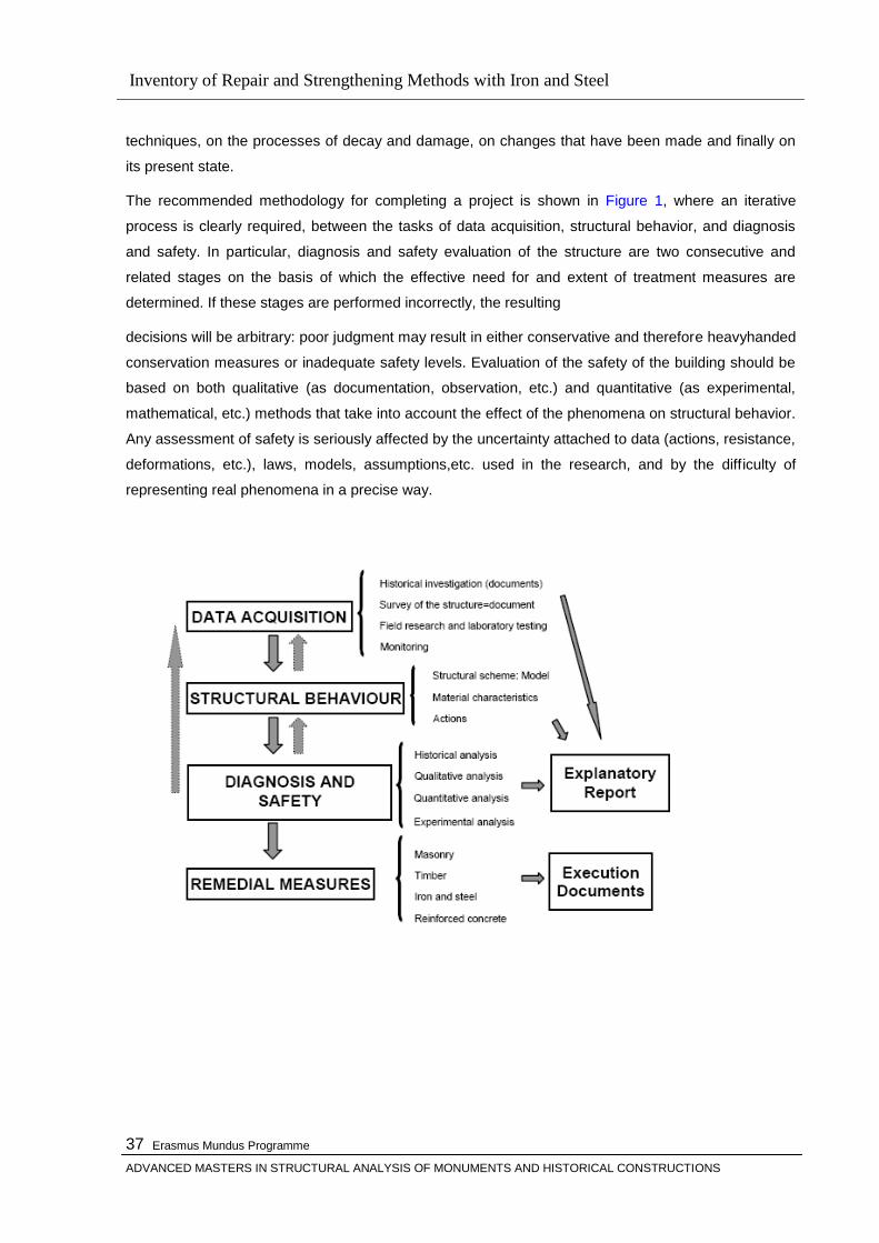
Inventory of Repair and Strengthening Methods with Iron and Steel
Erasmus Mundus Programme
ADVANCED MASTERS IN STRUCTURAL ANALYSIS OF MONUMENTS AND HISTORICAL CONSTRUCTIONS
37
techniques, on the processes of decay and damage, on changes that have been made and finally on
its present state.
The recommended methodology for completing a project is shown in Figure 1, where an iterative
process is clearly required, between the tasks of data acquisition, structural behavior, and diagnosis
and safety. In particular, diagnosis and safety evaluation of the structure are two consecutive and
related stages on the basis of which the effective need for and extent of treatment measures are
determined. If these stages are performed incorrectly, the resulting
decisions will be arbitrary: poor judgment may result in either conservative and therefore heavyhanded
conservation measures or inadequate safety levels. Evaluation of the safety of the building should be
based on both qualitative (as documentation, observation, etc.) and quantitative (as experimental,
mathematical, etc.) methods that take into account the effect of the phenomena on structural behavior.
Any assessment of safety is seriously affected by the uncertainty attached to data (actions, resistance,
deformations, etc.), laws, models, assumptions,etc. used in the research, and by the difficulty of
representing real phenomena in a precise way.

Inventory of Repair and Strengthening Methods with Iron and Steel
Erasmus Mundus Programme
ADVANCED MASTERS IN STRUCTURAL ANALYSIS OF MONUMENTS AND HISTORICAL CONSTRUCTIONS
38
Inventory of Repair and Strengthening Methods with Iron and Steel
Erasmus Mundus Programme
ADVANCED MASTERS IN STRUCTURAL ANALYSIS OF MONUMENTS AND HISTORICAL CONSTRUCTIONS
39
CHAPTER 3
HISTORIC PERSPECTIVE FOR MASONARY STRUCTURES
3.1 Historical Background
Masonry is one of the oldest construction material and tracing back the use of masonry will take us to
the history of the civilization. It is not an exageration to say that masonry represents civilization. From
the first ruble walls of the Stone Age to contemporary brick vener systems, it is masonry the architects
and engineers turn to when performance, solidity, aesthetics are sought the evolution of which is
parallel to the one of civilation.
Dictionary definition of masonry is as the ―work of a mason‖. It includes several loosely related
materials-brick, stone, concrete, and the tile-that are manufacture as relatively small units and bonded
together in the field, usually by mortar. All these various kinds of masonry can provide strenght,
protection from weather, security, and fire and sound resistance, although their structural behavior is
slightly different.
The distinctions between design and construction, particularly in the past, have not always been clear;
the two were at times mutually inclusive. For, until Renaissance, the master mason and master
carpenter served in two capacities, at once )in modern terminology) both artchitect and contractor.
Consequently, it is sometimes difficult to differentiate the two functions. Therefore, there are many
situations which should be treated in a sense to consider that the practical issues have influenced the
engineering or architectural design. A gothic cathedral was designed by a man who was both
architect and engineer-or, of course, by a succession of such men, if the building campaigns spread
over decades (Heyman, The Stone Skeleton). The ―master of the work‖ had survived the long training
of apprentice to journeyman to the caree grade of master, and had been one of those few outstanding
masters who ere put to school again in the design office, before finally achieving control of a major
work. This educational path contrasts strongly with that of modern Western European practice, which
is based upon Rennaissance concept of the ―gentlemen‖ architect, for whom considerations of history
and aesthetics are divorced tos ome extent from those of engineering structure. If the building is
complex, then the architect must work hand in hand with a technical adviser. There was not this
division in the thirteenth century (or in the sixth, when Justinian employed two outstanding Greeks,
Anthemios and Isidorus, to design Hagia Sofia). The architect then knew, in the fullest technical
sense, how to build, as well as how to give hşs building an ―architectural‖ design. Harvey (1958) has
discussed this: The Gothic rules were so complicated that no one who had not served a long
apprenticeship and pent years of practice could master them; whereas the rules of Vitrivius were so
easy to grasp that even bishops could understand them, and princes could try their hand at design on
their own‖
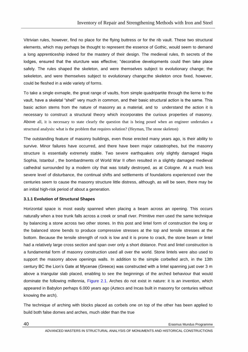
Inventory of Repair and Strengthening Methods with Iron and Steel
Erasmus Mundus Programme
ADVANCED MASTERS IN STRUCTURAL ANALYSIS OF MONUMENTS AND HISTORICAL CONSTRUCTIONS
40
Vitrivian rules, however, find no place for the flying buttress or for the rib vault. These two structural
elements, which may perhaps be thought to represent the essence of Gothic, would seem to demand
a long apprenticeship indeed for the mastery of their design. The medieval rules, th secrets of the
lodges, ensured that the sturcture was effective; ―decorative developments could then take place
safely. The rules shaped the skeleton, and were themselves subject to evolutionary change; the
sekeleton, and were themselves subject to evolutionary change;the skeleton once fixed, however,
could be fleshed in a wide variety of forms.
To take a single exmaple, the great range of vaults, from simple quadripartite through the lierne to the
vault, have a skeletal ―shell‖ very much in common, and their basic structural action is the same. This
basic action stems from the nature of masonry as a material, and to understand the action it is
necessary to construct a structural theory which incorporates the curious properties of masonry.
Above all, it is necessary to state clearly the question that is being posed when an engineer undertakes a
structural analysis: what is the problem that requires solution? (Heyman, The stone skeleton)
The outstanding feature of masonry buildings, even those erected many years ago, is their ability to
survive. Minor failures have occurred, and there have been major catastrophes, but the masonry
structure is essentially extremely stable. Two severe earthquakes only slightly damaged Hagia
Sophia, Istanbul , the bombardments of World War II often resulted in a slightly damaged medieval
cathedral surrounded by a modern city that was totally destroyed, as at Cologne. At a much less
severe level of disturbance, the continual shifts and settlements of foundations experienced over the
centuries seem to cause the masonry structure little distress, although, as will be seen, there may be
an initial high-risk period of about a generation.
3.1.1 Evolution of Structural Shapes
Horizontal space is most easily spanned when placing a beam across an opening. This occurs
naturally when a tree trunk falls across a creek or small river. Primitive men used the same technique
by balancing a stone across two other stones. In this post and lintel form of construction the long or
the balanced stone bends to produce compressive stresses at the top and tensile stresses at the
bottom. Because the tensile strength of rock is low and it is prone to crack, the stone beam or lintel
had a relatively large cross section and span over only a short distance. Post and lintel construction is
a fundamental form of masonry construction used all over the world. Stone lintels were also used to
support the masonry above openings walls. In addition to the simple corbelled arch, in the 13th
century BC the Lion‘s Gate at Mycenae (Greece) was constructed with a lintel spanning just over 3 m
above a triangular slab placed, enabling to see the beginnings of the arched behaviour that would
dominate the following millennia, Figure 2.1. Arches do not exist in nature: it is an invention, which
appeared in Babylon perhaps 6.000 years ago (Aztecs and Incas built in masonry for centuries without
knowing the arch).
The technique of arching with blocks placed as corbels one on top of the other has been applied to
build both false domes and arches, much older than the true
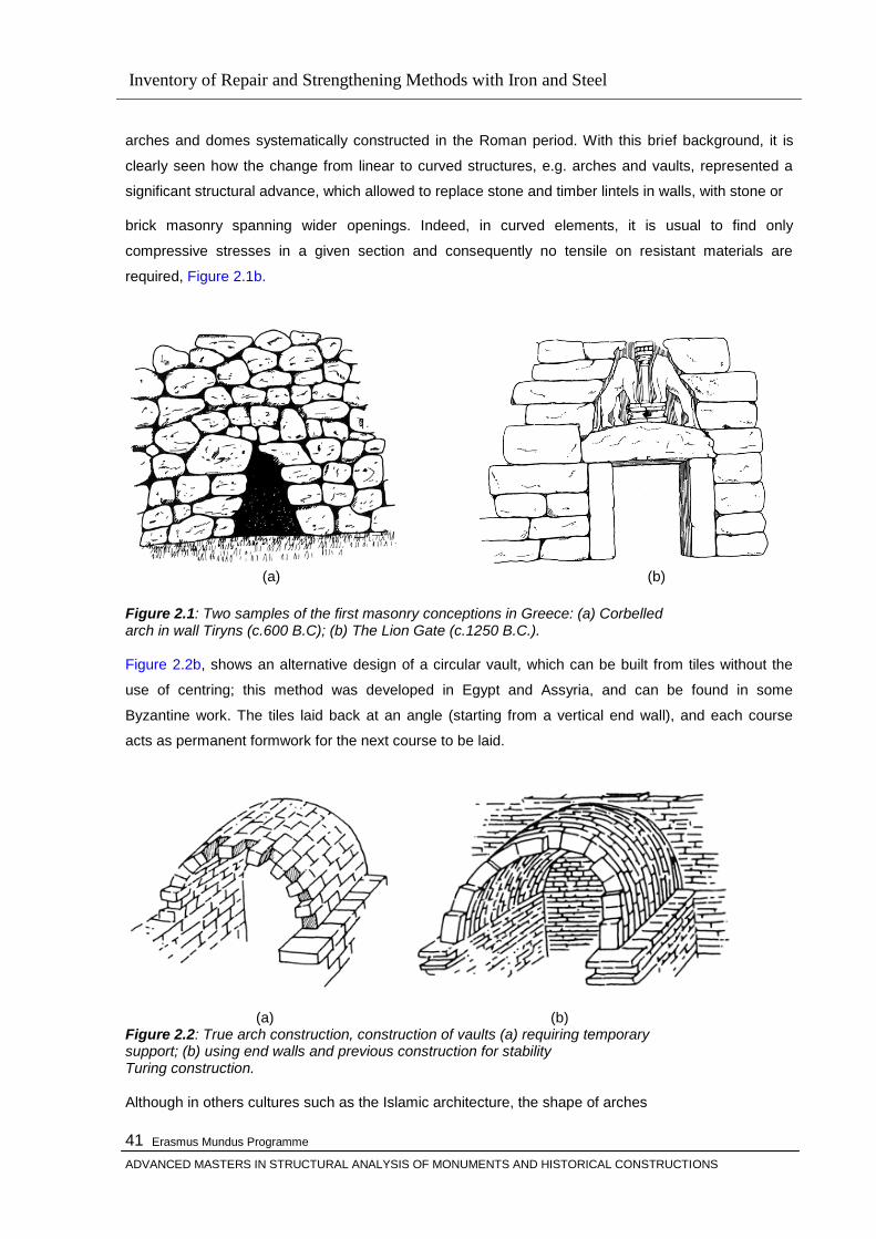
Inventory of Repair and Strengthening Methods with Iron and Steel
Erasmus Mundus Programme
ADVANCED MASTERS IN STRUCTURAL ANALYSIS OF MONUMENTS AND HISTORICAL CONSTRUCTIONS
41
arches and domes systematically constructed in the Roman period. With this brief background, it is
clearly seen how the change from linear to curved structures, e.g. arches and vaults, represented a
significant structural advance, which allowed to replace stone and timber lintels in walls, with stone or
brick masonry spanning wider openings. Indeed, in curved elements, it is usual to find only
compressive stresses in a given section and consequently no tensile on resistant materials are
required, Figure 2.1b.
(a) (b) Figure 2.1: Two samples of the first masonry conceptions in Greece: (a) Corbelled arch in wall Tiryns (c.600 B.C); (b) The Lion Gate (c.1250 B.C.). Figure 2.2b, shows an alternative design of a circular vault, which can be built from tiles without the
use of centring; this method was developed in Egypt and Assyria, and can be found in some
Byzantine work. The tiles laid back at an angle (starting from a vertical end wall), and each course
acts as permanent formwork for the next course to be laid.
(a) (b) Figure 2.2: True arch construction, construction of vaults (a) requiring temporary support; (b) using end walls and previous construction for stability Turing construction. Although in others cultures such as the Islamic architecture, the shape of arches

Inventory of Repair and Strengthening Methods with Iron and Steel
Erasmus Mundus Programme
ADVANCED MASTERS IN STRUCTURAL ANALYSIS OF MONUMENTS AND HISTORICAL CONSTRUCTIONS
42
and domes was often dictated by architecture intentions than by structural efficiency. The arch was the
structural element that best exploited the characteristic of masonry and for two thousand years it was
also the dominant feature of bridges.
Vaults and domes
Vault represents the three dimensional extension of the arch in space, although their initial beginnings,
its techniques of construction and materials are different. Potentially the vault has a big advantage in
relation to the arch: its two dimensional behaviour, which may be considered as an individual series or
arches (meridians) and parallels in domes with bending moments.
Another structural element that encloses space is the dome. This can be thought of as the shape
formed by the rotation of an arch about its vertical axis. Once again the earliest domes were formed by
the corbelling technique which leads to a fairly pointed dome. In this case, each course of masonry
forms a horizontal ring in which, to some extent, each masonry units is prevented from unbalancing
by adjacent unit forming a compression ring. Great ingenuity was often shown in combining barrels
vaults to create pleasing buildings. The culmination of this development was the cross vault, or groin
vault, so named after the lines created by its intersecting surfaces. Examples of vaults
are shown in Figure 2.3.
Figure 2.3: Examples of combined barrels: (a) single vault; (b) series of vaults; (c) lateral vaults (normal); (d) lateral vaults parallel; (e) cross or groin vault and (f) multiple cross groin vault.

Inventory of Repair and Strengthening Methods with Iron and Steel
Erasmus Mundus Programme
ADVANCED MASTERS IN STRUCTURAL ANALYSIS OF MONUMENTS AND HISTORICAL CONSTRUCTIONS
43
Hemispherical domes were set upon cylindrical walls or more interestingly over polygonal or even
square supporting walls. In latter cases, the supporting walls were made thick enough to contain the
base of the dome or thinner walls used with lintels or arches spanning across the corners to support
the dome. There is another elegant solution, to support a dome over a square plan area, using
portions of another hemispherical surface called a pendentive dome. In this solution the top dome had
a diameter equal to the side of the square area below. The pendentive dome was a hemisphere
encompassing the square below, but truncated at the base of the top dome and the vertical side of the
square as indicated in Figure 2.4a. In domes where stresses in the parallel directions exceed the weak
tensile strength, cracks along the meridians occur, and as the cracks increase, the behaviour
approaches that of independent arches, defined by the arches along the meridians, the bending
moments may then become significant and unstable situations
may occur (Croci 1998). Interesting and efficient roof structures can be generated on a rectangular
grid by using variations of this junction illustrate in Figure 2.4b.
(a) (b) Figure 2.4: (a) combinations of domes and vaults; (b) intersections of a pointed vaults.
3.2 Structural Aspects of Historic Masonry Buildings
Masonry is a collection of dry stones (or bricks etc), sometimes squared and well-fitted, sometimes left
unworked, that are placed one on another to form a stable structure. Mortar may be used to fill
interstices, but this mortar will have been weak initially, may have decayed with time and cannot be
assumed to add strength to the construction. Thus an arch built by assembling wedge-shaped stones
(voussoirs) upon centering will stand when the centering is removed. Gravity ensures that each stone
presses on the next, and a state of compression exists throughout the masonry. If the arch were
inverted it would fly apart, unless there were strong adhesive (mortar) between the stones that would
help them to resist the disintegrating tensile forces. Stability of a whole masonry structure is assured
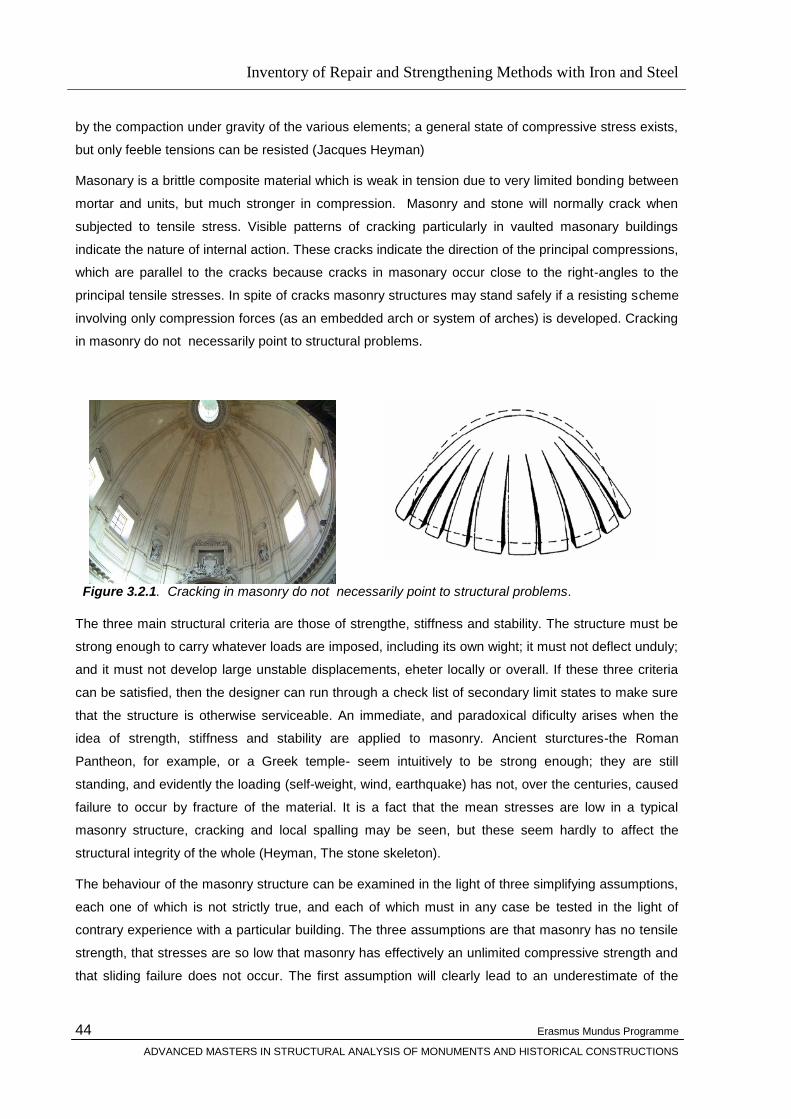
Inventory of Repair and Strengthening Methods with Iron and Steel
Erasmus Mundus Programme
ADVANCED MASTERS IN STRUCTURAL ANALYSIS OF MONUMENTS AND HISTORICAL CONSTRUCTIONS
44
by the compaction under gravity of the various elements; a general state of compressive stress exists,
but only feeble tensions can be resisted (Jacques Heyman)
Masonary is a brittle composite material which is weak in tension due to very limited bonding between
mortar and units, but much stronger in compression. Masonry and stone will normally crack when
subjected to tensile stress. Visible patterns of cracking particularly in vaulted masonary buildings
indicate the nature of internal action. These cracks indicate the direction of the principal compressions,
which are parallel to the cracks because cracks in masonary occur close to the right-angles to the
principal tensile stresses. In spite of cracks masonry structures may stand safely if a resisting scheme
involving only compression forces (as an embedded arch or system of arches) is developed. Cracking
in masonry do not necessarily point to structural problems.
Figure 3.2.1. Cracking in masonry do not necessarily point to structural problems. The three main structural criteria are those of strengthe, stiffness and stability. The structure must be
strong enough to carry whatever loads are imposed, including its own wight; it must not deflect unduly;
and it must not develop large unstable displacements, eheter locally or overall. If these three criteria
can be satisfied, then the designer can run through a check list of secondary limit states to make sure
that the structure is otherwise serviceable. An immediate, and paradoxical dificulty arises when the
idea of strength, stiffness and stability are applied to masonry. Ancient sturctures-the Roman
Pantheon, for example, or a Greek temple- seem intuitively to be strong enough; they are still
standing, and evidently the loading (self-weight, wind, earthquake) has not, over the centuries, caused
failure to occur by fracture of the material. It is a fact that the mean stresses are low in a typical
masonry structure, cracking and local spalling may be seen, but these seem hardly to affect the
structural integrity of the whole (Heyman, The stone skeleton).
The behaviour of the masonry structure can be examined in the light of three simplifying assumptions,
each one of which is not strictly true, and each of which must in any case be tested in the light of
contrary experience with a particular building. The three assumptions are that masonry has no tensile
strength, that stresses are so low that masonry has effectively an unlimited compressive strength and
that sliding failure does not occur. The first assumption will clearly lead to an underestimate of the
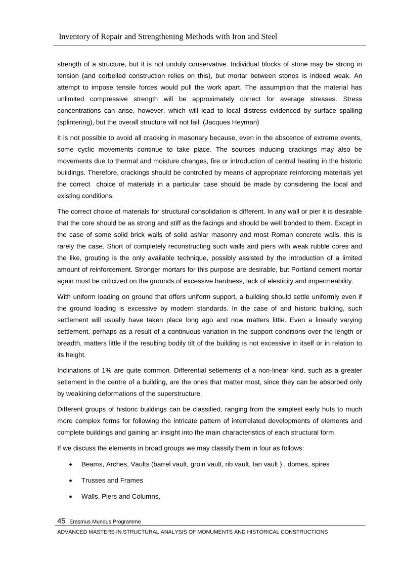
Inventory of Repair and Strengthening Methods with Iron and Steel
Erasmus Mundus Programme
ADVANCED MASTERS IN STRUCTURAL ANALYSIS OF MONUMENTS AND HISTORICAL CONSTRUCTIONS
45
strength of a structure, but it is not unduly conservative. Individual blocks of stone may be strong in
tension (and corbelled construction relies on this), but mortar between stones is indeed weak. An
attempt to impose tensile forces would pull the work apart. The assumption that the material has
unlimited compressive strength will be approximately correct for average stresses. Stress
concentrations can arise, however, which will lead to local distress evidenced by surface spalling
(splintering), but the overall structure will not fail. (Jacques Heyman)
It is not possible to avoid all cracking in masonary because, even in the abscence of extreme events,
some cyclic movements continue to take place. The sources inducing crackings may also be
movements due to thermal and moisture changes, fire or introduction of central heating in the historic
buildings. Therefore, crackings should be controlled by means of appropriate reinforcing materials yet
the correct choice of materials in a particular case should be made by considering the local and
existing conditions.
The correct choice of materials for structural consolidation is different. In any wall or pier it is desirable
that the core should be as strong and stiff as the facings and should be well bonded to them. Except in
the case of some solid brick walls of solid ashlar masonry and most Roman concrete walls, this is
rarely the case. Short of completely reconstructing such walls and piers with weak rubble cores and
the like, grouting is the only available technique, possibly assisted by the introduction of a limited
amount of reinforcement. Stronger mortars for this purpose are desirable, but Portland cement mortar
again must be criticized on the grounds of excessive hardness, lack of elesticity and impermeability.
With uniform loading on ground that offers uniform support, a building should settle uniformly even if
the ground loading is excessive by modern standards. In the case of and historic building, such
settlement will usually have taken place long ago and now matters little. Even a linearly varying
settlement, perhaps as a result of a continuous variation in the support conditions over the length or
breadth, matters little if the resulting bodily tilt of the building is not excessive in itself or in relation to
its height.
Inclinations of 1% are quite common. Differential setlements of a non-linear kind, such as a greater
setlement in the centre of a building, are the ones that matter most, since they can be absorbed only
by weakining deformations of the superstructure.
Different groups of historic buildings can be classified, ranging from the simplest early huts to much
more complex forms for following the intricate pattern of interrelated developments of elements and
complete buildings and gaining an insight into the main characteristics of each structural form.
If we discuss the elements in broad groups we may classify them in four as follows:
Beams, Arches, Vaults (barrel vault, groin vault, rib vault, fan vault ) , domes, spires
Trusses and Frames
Walls, Piers and Columns,

Inventory of Repair and Strengthening Methods with Iron and Steel
Erasmus Mundus Programme
ADVANCED MASTERS IN STRUCTURAL ANALYSIS OF MONUMENTS AND HISTORICAL CONSTRUCTIONS
46
Foundations
Classifications and general understandings of the essential characteristics and typical maladies of
different structural groups are a helpful tool to understand the individual yet one must not forget that
they should not be regarded as more than a starting point and each building must be considered as a
unique individual structure to care it properly.
Each sturcture must be considered as a whole before making an assesment because, for instance
considering the stability of an arch without considering its supports and the stability of the ground on
which they rest will not be sufficient to diagnosing the maladies of the building.
Arches
Arches must be considered in the context of the wall or arcade in which they are situated and of the
thrust they exert in which they are situated and of the thrsut they exert on their abutments. Pointed
and parapolic arches are special cases. The hinging effects is most relevant when the depth of the
voussoirs is small in relation to the span. When voussoirs are deep in relation to span, arches are able
to absorb deformations generally by slipping, as in the case of the Colosseum. In all cases the
condition of the abutments is vital to arches. If these supports are sliding, sinking or rotating, the
stability of the arch itself is suspect; therefore, the abutments always need most careful consideration.
The sources of stress in arches come from the weihgt of the structure, dead loading and applied
loads. In long-span masonary arches the dead load sometimes caused collapse when the shuttering
was removed. Stresses can be increased by the settlement of an abutment.
Loads can be calculated by graphical means and then lines of thrust can be shown. Such diadrams
are very helpful when investigating stresses in an arched construction.
According the Heyman (1982) hypothesis the behaviour of arches and vaults can be explained as
follows:
Figure 3.2.2
The masonary has a well known neglgible tensile strength, so the safety condition for masonary arches is a chieved when the line of thrust, coincident with the funicular polygon, is kept inside of each section of the arch itself. When the resultant of the internal forces moves outside the central core, the section partialises and a phase of high deformations starts (Heyman 1982)
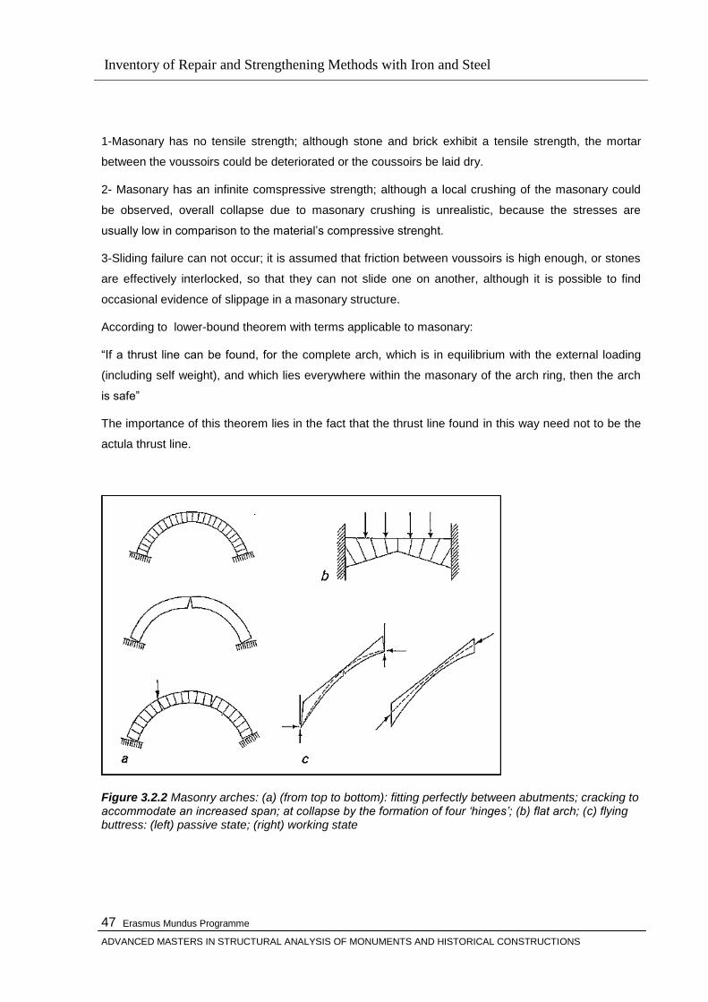
Inventory of Repair and Strengthening Methods with Iron and Steel
Erasmus Mundus Programme
ADVANCED MASTERS IN STRUCTURAL ANALYSIS OF MONUMENTS AND HISTORICAL CONSTRUCTIONS
47
1-Masonary has no tensile strength; although stone and brick exhibit a tensile strength, the mortar
between the voussoirs could be deteriorated or the coussoirs be laid dry.
2- Masonary has an infinite comspressive strength; although a local crushing of the masonary could
be observed, overall collapse due to masonary crushing is unrealistic, because the stresses are
usually low in comparison to the material‘s compressive strenght.
3-Sliding failure can not occur; it is assumed that friction between voussoirs is high enough, or stones
are effectively interlocked, so that they can not slide one on another, although it is possible to find
occasional evidence of slippage in a masonary structure.
According to lower-bound theorem with terms applicable to masonary:
―If a thrust line can be found, for the complete arch, which is in equilibrium with the external loading
(including self weight), and which lies everywhere within the masonary of the arch ring, then the arch
is safe‖
The importance of this theorem lies in the fact that the thrust line found in this way need not to be the
actula thrust line.
Figure 3.2.2 Masonry arches: (a) (from top to bottom): fitting perfectly between abutments; cracking to accommodate an increased span; at collapse by the formation of four „hinges‟; (b) flat arch; (c) flying buttress: (left) passive state; (right) working state
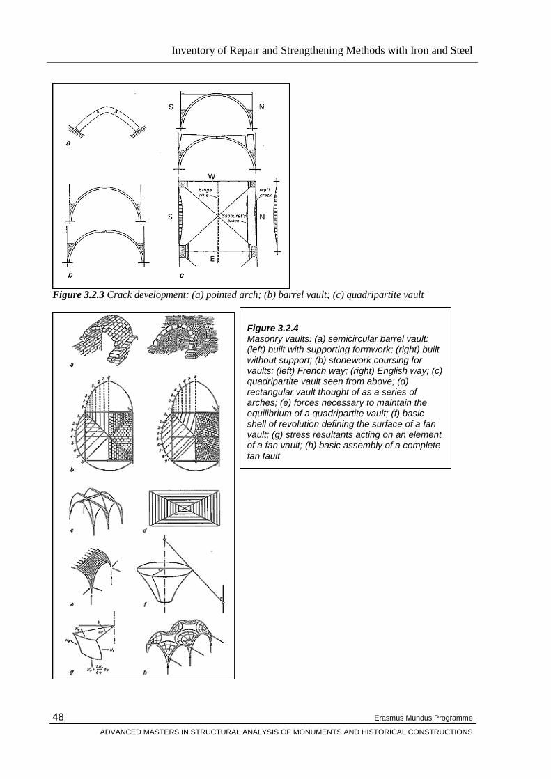
Inventory of Repair and Strengthening Methods with Iron and Steel
Erasmus Mundus Programme
ADVANCED MASTERS IN STRUCTURAL ANALYSIS OF MONUMENTS AND HISTORICAL CONSTRUCTIONS
48
Figure 3.2.3 Crack development: (a) pointed arch; (b) barrel vault; (c) quadripartite vault
Figure 3.2.4 Masonry vaults: (a) semicircular barrel vault: (left) built with supporting formwork; (right) built without support; (b) stonework coursing for vaults: (left) French way; (right) English way; (c) quadripartite vault seen from above; (d) rectangular vault thought of as a series of arches; (e) forces necessary to maintain the equilibrium of a quadripartite vault; (f) basic shell of revolution defining the surface of a fan vault; (g) stress resultants acting on an element of a fan vault; (h) basic assembly of a complete fan fault

Inventory of Repair and Strengthening Methods with Iron and Steel
Erasmus Mundus Programme
ADVANCED MASTERS IN STRUCTURAL ANALYSIS OF MONUMENTS AND HISTORICAL CONSTRUCTIONS
49
Figure 3.2.5 Masonry domes: (a) membrane hoop stresses acting in a thin hemispherical dome; (b) minimum thickness for a sliced masonry dome; (c) an „arch‟ isolated from a dome by meridional cuts
Figure 3.2.6 Flying buttresses at Amiens Cathedral: (a) limiting positions for the thrust lines in the lower rib; (b) possible buckling mode of failure

Inventory of Repair and Strengthening Methods with Iron and Steel
Erasmus Mundus Programme
ADVANCED MASTERS IN STRUCTURAL ANALYSIS OF MONUMENTS AND HISTORICAL CONSTRUCTIONS
50
3.3. Materials Used in Historic Buildings
Bernard M Fielden, in his book- Conservation of Historic Buildings, gives a description for “an historic
building”
―Briefly, an historic building is one that gives us a sense of wonder and makes us want to know more about the
people and culture that produced it. It has architectural, aesthetic, historic, documentary, archaeological,
economic, social and even political and spiritual or symbolic values; but the first impact is always emotional, for
it is a symbol of our cultural identity and continuity—a part of our heritage. If it has survived the hazards of 100
years of usefulness, it has a good claim to being called historic.‖
It is, therefore, essential to study Its structural and material condition which means investifating the
different phases of construction of the building complex, interventions throughout its life , any internal
or external peculiarities and the environmental context of the surroundings of the building.
The two main structural materials found in historic buildings are timber and masonry. Members of
timber systems can resist tension as well as compression, and the joints can resist tension, but the
strength of the total system is limited by the strength of the joints. The span is limited by the length of
timber available. Known timber structural systems include, for walls, solid timber tree trunks set
vertically or horizontally, post and lintel systems, box frames and cruck framing, and for roofs, simple
beams, rafters and tie beams, trussed beams, arch braced beams, hammerbeam trusses and framed
trusses. Masonry structural systems include simple post and lintel systems, as for timber, but the
commonest sort of masonry system is mass construction with pierced openings; stone skeleton
frames were devised for sophisticated Gothic buildings with pointed arch and flying buttress, through
which the lines of thrust were intended to flow within the physical limits of the masonry. In contrast to
timber, the total strength depends more on the compressive strength of the materials rather than on
the joints.
In the case of stone, its strength, quarrying facilities, lifting and transportation were also vital
considerations. The longest stone beams known are in Fukien, China. They are 23 m (75 ft) long, are
of granite and were used to build a multi-span bridge. Calculations show that the tensile strength of
the stone is just sufficient to support this length. The length of wooden beams is limited by the length
of available timbers. [25]
If we compare the main structural materials used in historic buildings (stone, brick, mass concrete and
timber) with cast iron and wrought iron, structural steel and aluminium alloy with respect to the tensile
and compressive strength, density and stiffness , striking differences are found. Except for timber,
historic materials are all very weak in tension, whereas the materials used in the nineteenth century
and later, with the possible exception of cast iron, are strong in tension and exceptionally so in
compression. Wrought iron, even the weakest of them, exceeds the best stone in compressive
strength.
Inventory of Repair and Strengthening Methods with Iron and Steel
Erasmus Mundus Programme
ADVANCED MASTERS IN STRUCTURAL ANALYSIS OF MONUMENTS AND HISTORICAL CONSTRUCTIONS
51
All the main materials available now in use are derived from the same basic materials that have been
used for thousands of years—earth, rock, timber and metals—but have been improved in utilization
and manufacture. Other new materials, such as plastics, synthetic resins and aluminium, lack stiffness
in practice, so play a secondary role in construction, because for most structural purposes stiffness is
as important as strength. In the context of historic buildings, reinforced concrete must be considered a
new material.
3.4 Causes of Decay in Materials and Structure
Of the causes of decay in an historic building, the most important and universal ones are:
Gravity and the structural actions resulting from gravity, (Gravity is both the force that keeps
buildings standing and the major cause of their destruction).
Actions of man
Diverse climatic and environmental effects—botanical, biological, chemical and entomological.
when analysing the causes of deterioration and loss in an historic building, the following issues must
be studied:
(1) What are the weaknesses and strengths inherent in the structural design and the component
materials of the object?
(2) What are the possible natural agents of deterioration that could affect the component materials?
How rapid is their action?
(3) What are the possible human agents of deterioration that could affect the component materials or
structure? How much of their effect can be reduced at source.
Man-made causes of decay are serious and can only be reduced by forethought and international co-
operation. Neglect and ignorance are possibly the major causes of destruction by man, coupled with
vandalism and fires.

Inventory of Repair and Strengthening Methods with Iron and Steel
Erasmus Mundus Programme
ADVANCED MASTERS IN STRUCTURAL ANALYSIS OF MONUMENTS AND HISTORICAL CONSTRUCTIONS
52
Inventory of Repair and Strengthening Methods with Iron and Steel
Erasmus Mundus Programme
ADVANCED MASTERS IN STRUCTURAL ANALYSIS OF MONUMENTS AND HISTORICAL CONSTRUCTIONS
53
CHAPTER 4
EVALUATION & ASSESMENT of EXISTING MASONARY BUILDINGS
4.1 Investigation
In order to diagnose the causes of decay and propose an effective cure that involves only the
minimum intervention, it is an essential preliminary before embarking upon historical research or any further
study of the structure such as structural analysis, including soil mechanics, investigations to carry out a
proper assesment & investigation works which should be reported to include the following main items:
Initial report based upon visual inspection, listing all defects and describing and studying the
building.
A maintenance plan. Approximate itemized estimates for immediate, urgent, and necessary
repairs and other desirable works.
Historical research and analysis supported by photographic records.
Recording of the initial state of the building; soil mechanics, humidity studies and opening up
suspect parts.
Further studies. Structural analysis.
Final estimates and proposals with specifications and full report for submission for
governmental
grant covering all the above factors, as they modify each other.
4.2 Decision Making
Clear recommendations for action must follow from an initial investigation.
Recommendations must be scaled to what is possible in the context of the situation. They should be
given in order of priority as follows:
(1) Immediate work is what must be done straight away to deal with work necessary for the safety of the
fabric or its users.
(2) Urgent work is that required to prevent active deterioration, i.e. attack by insect or fungus or
penetration by rain water.
(3) Necessary work is that required to the ‗standard‘ appropriate for the building and its present or
proposed use in the context of the client‘s resources and includes items of preventive
maintenance. This category can be subdivided into ‗good housekeeping‘, ‗rolling programme‘ and
‗major works‘.
Inventory of Repair and Strengthening Methods with Iron and Steel
Erasmus Mundus Programme
ADVANCED MASTERS IN STRUCTURAL ANALYSIS OF MONUMENTS AND HISTORICAL CONSTRUCTIONS
54
(4) Desirable work is what is recommended to enhance the use or appearance of the building or what is
necessary for re-evaluation or adaptive use of the building.
(5) Items to be kept under observation are, for example, active movements and roofs or installations that
are nearing the end of their life and may need renewal within 10 or 15 years.
Where remedial interventions are considered to be necessary, they should respect, as far as possible,
the philosophy of compatibility( i.e. compatibility with the character and integrity of the original
structure). The materials similar to the original ones, should be utilized, as far as possible. Where
different materials are substituted, their physical characteristics should be compatible with the
original, particularly with regard to porosity and permeability, and care should be taken not to introduce
elements of excessive strength or stiffness into a structure which will usually be less stiff and more
accommodating to long-term movements than contemporary structures. The final choice of the
approach to be adopted should be made only after a proper appraisal (consistent with the scale of
operations and the resources available) of alternatives, with some eye to the future such that an action
of intervention may be substituted with a better technique in the future.
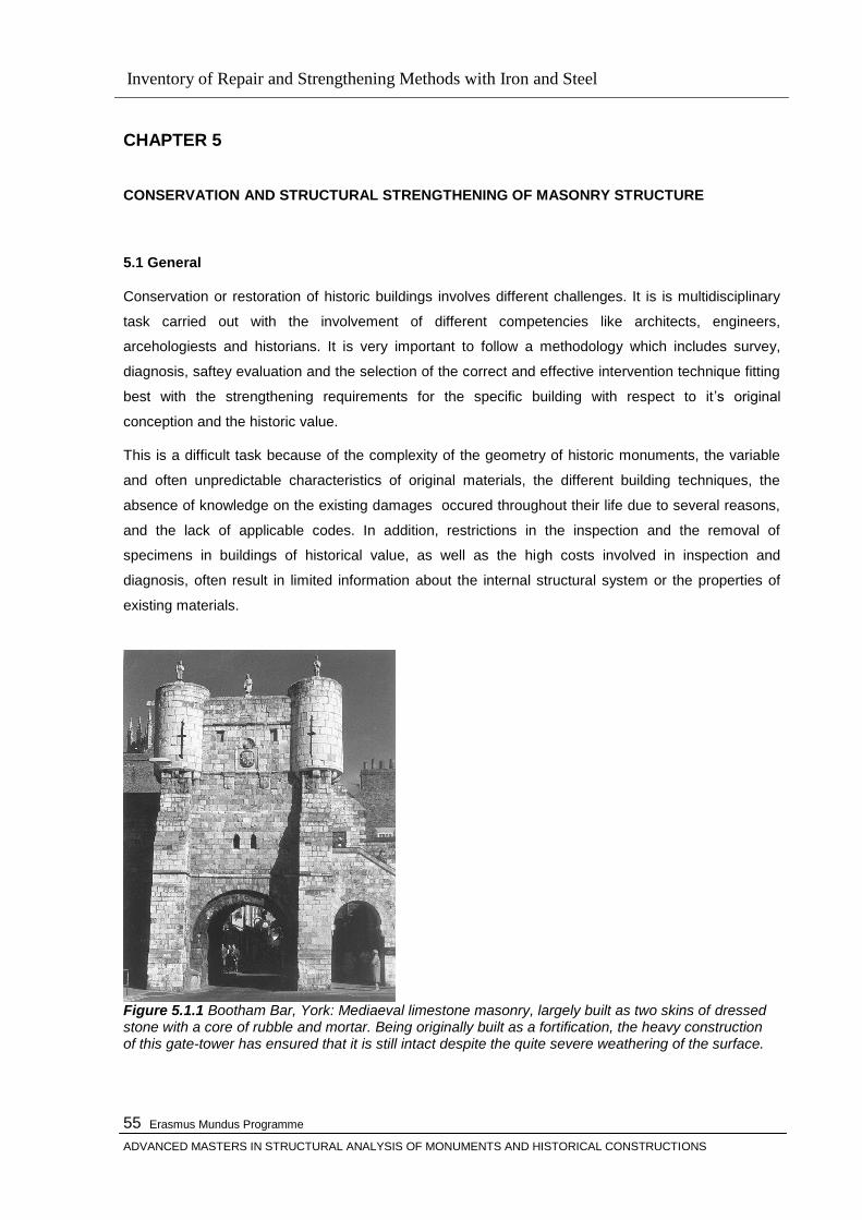
Inventory of Repair and Strengthening Methods with Iron and Steel
Erasmus Mundus Programme
ADVANCED MASTERS IN STRUCTURAL ANALYSIS OF MONUMENTS AND HISTORICAL CONSTRUCTIONS
55
CHAPTER 5
CONSERVATION AND STRUCTURAL STRENGTHENING OF MASONRY STRUCTURE
5.1 General
Conservation or restoration of historic buildings involves different challenges. It is is multidisciplinary
task carried out with the involvement of different competencies like architects, engineers,
arcehologiests and historians. It is very important to follow a methodology which includes survey,
diagnosis, saftey evaluation and the selection of the correct and effective intervention technique fitting
best with the strengthening requirements for the specific building with respect to it‘s original
conception and the historic value.
This is a difficult task because of the complexity of the geometry of historic monuments, the variable
and often unpredictable characteristics of original materials, the different building techniques, the
absence of knowledge on the existing damages occured throughout their life due to several reasons,
and the lack of applicable codes. In addition, restrictions in the inspection and the removal of
specimens in buildings of historical value, as well as the high costs involved in inspection and
diagnosis, often result in limited information about the internal structural system or the properties of
existing materials.
Figure 5.1.1 Bootham Bar, York: Mediaeval limestone masonry, largely built as two skins of dressed stone with a core of rubble and mortar. Being originally built as a fortification, the heavy construction of this gate-tower has ensured that it is still intact despite the quite severe weathering of the surface.
Inventory of Repair and Strengthening Methods with Iron and Steel
Erasmus Mundus Programme
ADVANCED MASTERS IN STRUCTURAL ANALYSIS OF MONUMENTS AND HISTORICAL CONSTRUCTIONS
56
Although there are a lot of materials and intervention techniques available for structural restorations
recent philosophy underlying restoration recommends to prefer prefer techniques that are fullfilling the
criterias like minimum intervention, compatibility, durability, reversibility or substitutability. In principle
this philosophy is correct, but one should not forget that any decission may not always be error-free
and it is therefore unwise to exclude the possibility of exploiting better techniques and materials if and
when they are developed. conservation requirements .
A full understanding of the structural behaviour and material characteristics is essential for any project
related to architectural heritage. Diagnosis is based on historical information and qualitative and
quantitative approaches. The qualitative approach is based on direct observation of the structural
damage and material decay as well as historical and archaeological research, while the quantitative
approach requires material and structural tests, monitoring and structural analysis. Often the
application of the same safety levels used in the design of new buildings requires excessive, if not
impossible, measures. In these cases other methods, appropriately justified, may allow different
approaches to safety.
5.2 Stabilization & Repair & Strengthening Techniques with Iron and Steel
An early reference to iron ties is given in Richard Brown, Sacred Architecture. This book by Professor
Brown, who designated himself an architect, is uneven and not very significant for our purpose [35].
But on p.107, in speaking of the construction of Beauvais Ctahedral in the thritieenth century, he says:
―At this time, the pillars being placed too far apart, the vaulted roof threatened to fall in, which actually
took place after means had been adopted to support it by iron braces and chain, to hold the side walls
together‖.
Lethaby (King‘s Craftsmen, pp.145 f.) speaking of the ―new work‖ of Henry III at Westminster Abbey,
which began with the eastern and three northern bays of the apse.
In his later book (Westminster Abbey Reexamined, pp.103-5 and notes, p 297) Lethaby has more to
say about the use of iron in the Chapter Houses at Salisbury and Westmisnter, and includes a
perspective drawing of the interior of the latter with the tie-rods showing. He notes (p.105) that beside
the eight ties mentioned, the windows are threaded by three tiers of strong iron bars, which are still
wholly or largely original. One may assume thet they link up the angles and form bands right around
the octagon. Scott found, from the fact that the western window originally had four lights like the
others.
It appears from these and similar accounts that iron was used far more extensively to tie together the
masonry members in the great English Chruches than it was in those of France. Westminster would
seem to indicate that English builders progressed from wood ties (probably because the were so much
cheaper than iron ) , to continuous through-the pier iron ties, to eyed iron ties attached to projecting
iron hooks, to no ties at all: as though the the builders proficiency grew along with their increasing
confidence.
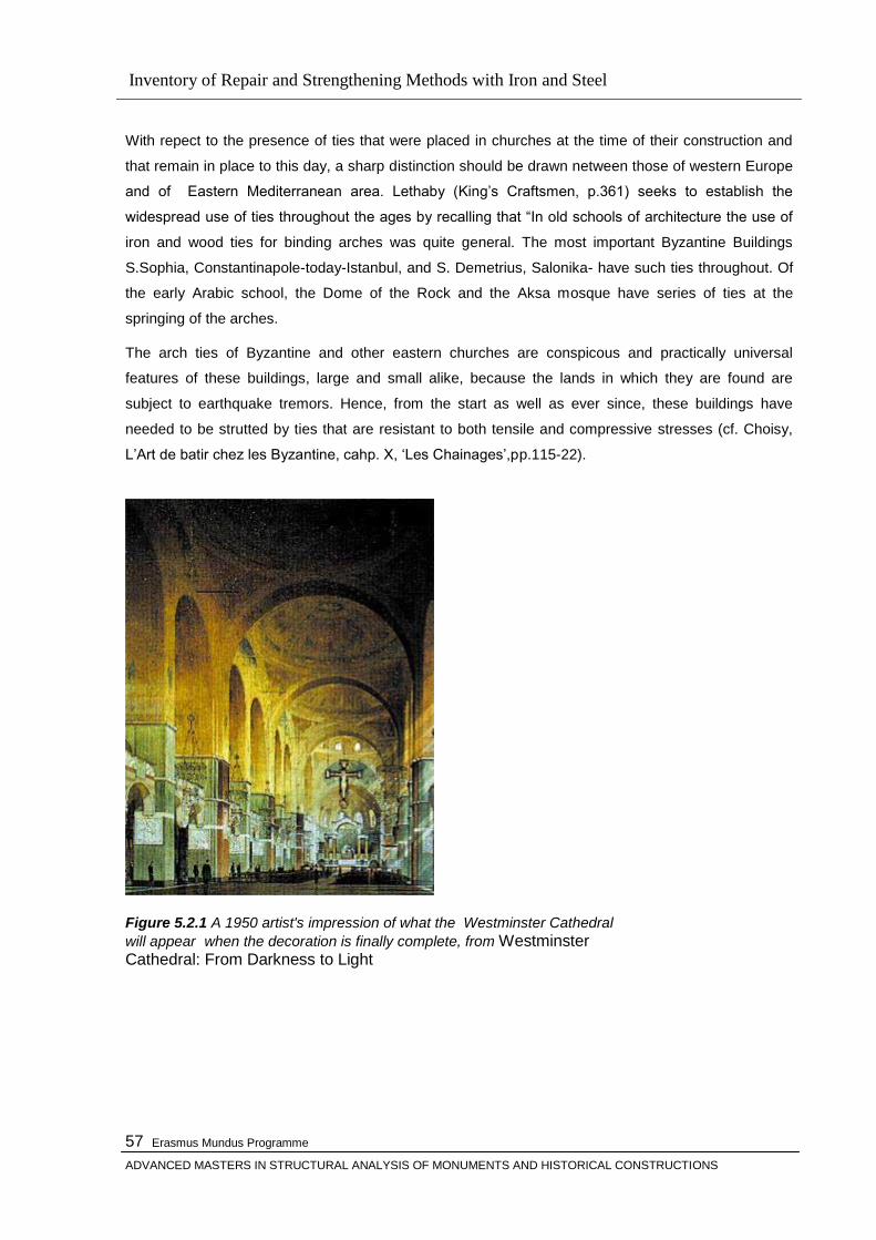
Inventory of Repair and Strengthening Methods with Iron and Steel
Erasmus Mundus Programme
ADVANCED MASTERS IN STRUCTURAL ANALYSIS OF MONUMENTS AND HISTORICAL CONSTRUCTIONS
57
With repect to the presence of ties that were placed in churches at the time of their construction and
that remain in place to this day, a sharp distinction should be drawn netween those of western Europe
and of Eastern Mediterranean area. Lethaby (King‘s Craftsmen, p.361) seeks to establish the
widespread use of ties throughout the ages by recalling that ―In old schools of architecture the use of
iron and wood ties for binding arches was quite general. The most important Byzantine Buildings
S.Sophia, Constantinapole-today-Istanbul, and S. Demetrius, Salonika- have such ties throughout. Of
the early Arabic school, the Dome of the Rock and the Aksa mosque have series of ties at the
springing of the arches.
The arch ties of Byzantine and other eastern churches are conspicous and practically universal
features of these buildings, large and small alike, because the lands in which they are found are
subject to earthquake tremors. Hence, from the start as well as ever since, these buildings have
needed to be strutted by ties that are resistant to both tensile and compressive stresses (cf. Choisy,
L‘Art de batir chez les Byzantine, cahp. X, ‗Les Chainages‘,pp.115-22).
Figure 5.2.1 A 1950 artist's impression of what the Westminster Cathedral
will appear when the decoration is finally complete, from Westminster Cathedral: From Darkness to Light
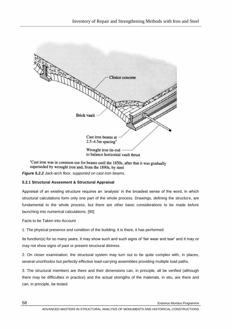
Inventory of Repair and Strengthening Methods with Iron and Steel
Erasmus Mundus Programme
ADVANCED MASTERS IN STRUCTURAL ANALYSIS OF MONUMENTS AND HISTORICAL CONSTRUCTIONS
58
Figure 5.2.2 Jack-arch floor, supported on cast-iron beams. 5.2.1 Structural Assesment & Structural Appraisal
Appraisal of an existing structure requires an ‗analysis‘ in the broadest sense of the word, in which
structural calculations form only one part of the whole process. Drawings, defining the structure, are
fundamental to the whole process, but there are other basic considerations to be made before
launching into numerical calculations. [90]
Facts to be Taken into Account
1. The physical presence and condition of the building; it is there, it has performed
its function(s) for so many years, it may show such and such signs of ‗fair wear and tear‘ and it may or
may not show signs of past or present structural distress.
2. On closer examination, the structural system may turn out to be quite complex with, in places,
several unorthodox but perfectly effective load-carrying assemblies providing multiple load paths.
3. The structural members are there and their dimensions can, in principle, all be verified (although
there may be difficulties in practice) and the actual strengths of the materials, in situ, are there and
can, in principle, be tested.
Inventory of Repair and Strengthening Methods with Iron and Steel
Erasmus Mundus Programme
ADVANCED MASTERS IN STRUCTURAL ANALYSIS OF MONUMENTS AND HISTORICAL CONSTRUCTIONS
59
Fact 1 can be, and should be, used as a qualitative check on any numerical assessment. If the
building stands up and the calculations show that it should have fallen down, the calculations or the
assumptions on which they are based must be wrong.
Fact 2 is likely to be a challenge, but unless the obvious primary system can be shown to be adequate
on its own, the challenge has to be faced by the engineer, even if it involves ‗non-linear analysis‘ of a
three-dimensional structure: to
do otherwise is tantamount to condemning a perfectly good structure out of laziness. ‗Linear-elastic‘
analysis assumes that Hooke‘s straight-line stress–strain relationship applies regardless of the stress
intensity; non-linear analysis takes account of the curvature of the real stress–strain diagram and of
any yielding of the material prior to fracture Fact 3 allows the elimination or reduction of some or all of
the design uncertainties (described in Sec. 2.3 of [90] ) and thus leads straight to Sec. 2.5. of [90] )

Inventory of Repair and Strengthening Methods with Iron and Steel
Erasmus Mundus Programme
ADVANCED MASTERS IN STRUCTURAL ANALYSIS OF MONUMENTS AND HISTORICAL CONSTRUCTIONS
60
Figure 5.2.1.1 Paths of improved appraisal (after „Appraisal of Existing Structures‟, 1996). [90]

Inventory of Repair and Strengthening Methods with Iron and Steel
Erasmus Mundus Programme
ADVANCED MASTERS IN STRUCTURAL ANALYSIS OF MONUMENTS AND HISTORICAL CONSTRUCTIONS
61
Figure 5.2.1.2 Example of drawing, showing measured and observed defects ( from Dowrick and Beckmann, 1971).Measurement of past and ongoing defects is the essential part of an assesment activity. Every structural appraisal must have a report as its end result covering Synopsis, List of contents,
Terms of reference, Documents examined, Description of the structure, Inspections, Additional
(verbal) information (if any) Sampling and testing (if any), Calculation checks (if any), Discussion of
evidence, Conclusions, Recommendations.
5.2.2 Causes of Damage
Masonry is generally relatively strong in compression, has a moderate resistance to sliding along the
bed-joints (shear) and is usually weak in tension. Masonry structures are therefore generally designed
to work in compression and sometimes in horizontal shear. Damage to masonry structures usually
takes the form of tension and/or shear cracks caused by imposed deformations, e.g. differential
settlement, or by excessive lateral forces, e.g. from arch thrusts; or alternatively it may suffer from
incipient bursting due to buckling of ashlar or expansion of rubble fill in structures that consist of two
ashlar faces with a core of rubble and mortar.
All unintended gaps in masonry are usually referred to as ‗cracks‘. For a proper assessment of causes
and significance, one should however distinguish between the following categories:
cracks through units,
opening of bedjoints and butt joints and
sliding‘ along bed-joints.

Inventory of Repair and Strengthening Methods with Iron and Steel
Erasmus Mundus Programme
ADVANCED MASTERS IN STRUCTURAL ANALYSIS OF MONUMENTS AND HISTORICAL CONSTRUCTIONS
62
Whilst all three may have structural implications (a) is more likely to lead to a risk to people from falling
bits of masonry.
Causes of damages may briefly be categorized as follows:
Cracks Due to Imposed Deformations
Cracks Due to Excessive Lateral Forces
Cracks Due to Eccentric Loading
Cracks Due to Embedded Ironwork
Defects in Brickwork Cladding on Reinforced Concrete-framed Buildings
Problems with Cavity-ties
It is obvious that repair or strengthening must be preceded by determining the real cause of the
observed defects, and if the cause is still active, it must be eliminated. Otherwise the repairs will be
short-lived. There is a parallel in the field of medicine: any treatment must be preceded by a correct
diagnosis.
The techniques used for repair or strengthening must depend on whether thecracks are ‗live‘, i.e. still
moving, or ‗dead‘, i.e. being due to a cause, which has been eliminated in the past. If the cracks are
live, the cause should be treated, if at all possible, and the subsequent repairs to the masonry will be
largely cosmetic.
5.2.3. Repair and Strengthening of walls and piers
Compatibility
For all types of construction, repair materials must be compatible with the original materials. This
applies to the stone or brick and the mortar. There has been many problems in the past due to
interventions with incompatible materials.
The quality of the repair mortar will influence the weathering performance of exposed masonry. If it is
too weak and porous, it will be eroded too quickly. If it is too strong, it will almost invariably be too
impervious (adding a small proportion of Portland cement in substitution of lime will only increase the
strength of the mortar marginally, but it will reduce its permeability significantly). It may then trap water
that has got into the units, e.g. from driving rain, and prevent it from draining down; such water,
lodging in the units over each impervious bed-joint, is likely to exacerbate frost damage in the form of
spalling-off of the face of the bricks or stones.
The other objection to the use of modern strong mortars is that they prevent the slight sliding of stones
or bricks on the bed-joints which, when walls are subjected to imposed deformations such as
differential settlement, usually only lead to minor cracking along the joints. With such sliding
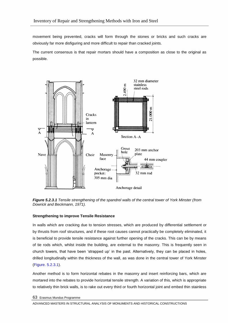
Inventory of Repair and Strengthening Methods with Iron and Steel
Erasmus Mundus Programme
ADVANCED MASTERS IN STRUCTURAL ANALYSIS OF MONUMENTS AND HISTORICAL CONSTRUCTIONS
63
movement being prevented, cracks will form through the stones or bricks and such cracks are
obviously far more disfiguring and more difficult to repair than cracked joints.
The current consensus is that repair mortars should have a composition as close to the original as
possible.
Figure 5.2.3.1 Tensile strengthening of the spandrel walls of the central tower of York Minster (from Dowrick and Beckmann, 1971).
Strengthening to improve Tensile Resistance
In walls which are cracking due to tension stresses, which are produced by differential settlement or
by thrusts from roof structures, and if these root causes cannot practically be completely eliminated, it
is beneficial to provide tensile resistance against further opening of the cracks. This can be by means
of tie rods which, whilst inside the building, are external to the masonry. This is frequently seen in
church towers, that have been ‗strapped up‘ in the past. Alternatively, they can be placed in holes,
drilled longitudinally within the thickness of the wall, as was done in the central tower of York Minster
(Figure. 5.2.3.1).
Another method is to form horizontal rebates in the masonry and insert reinforcing bars, which are
mortared into the rebates to provide horizontal tensile strength. A variation of this, which is appropriate
to relatively thin brick walls, is to rake out every third or fourth horizontal joint and embed thin stainless
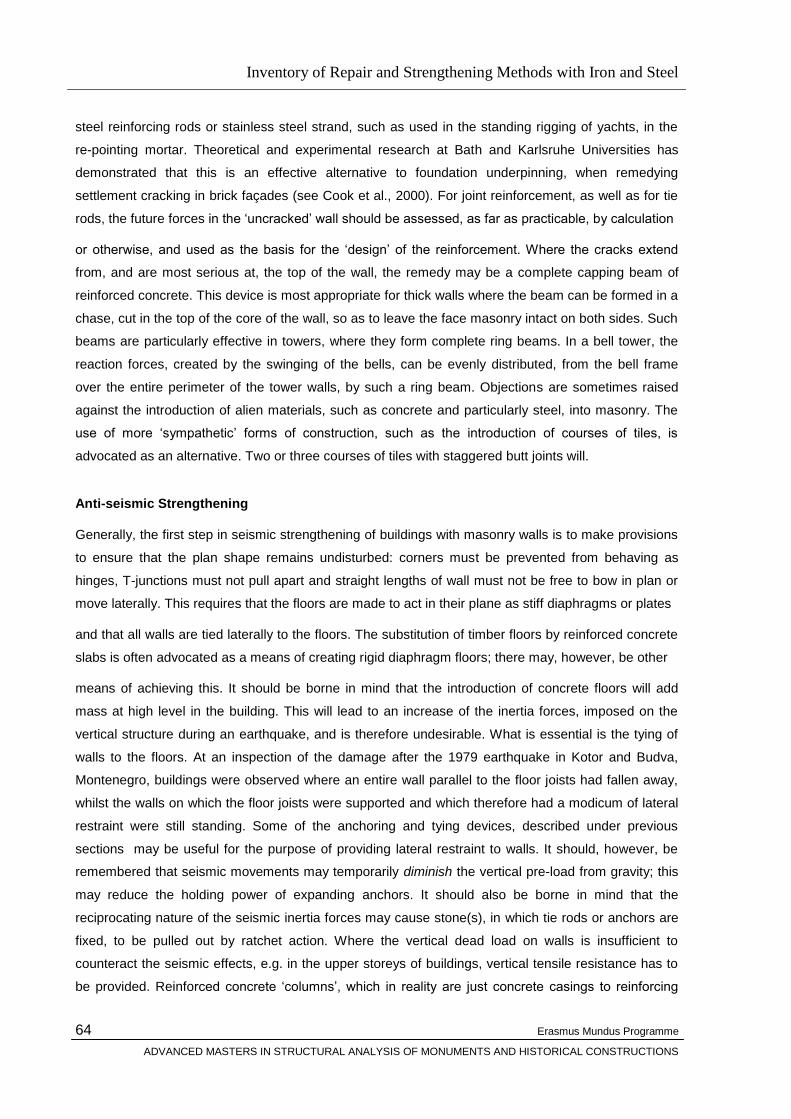
Inventory of Repair and Strengthening Methods with Iron and Steel
Erasmus Mundus Programme
ADVANCED MASTERS IN STRUCTURAL ANALYSIS OF MONUMENTS AND HISTORICAL CONSTRUCTIONS
64
steel reinforcing rods or stainless steel strand, such as used in the standing rigging of yachts, in the
re-pointing mortar. Theoretical and experimental research at Bath and Karlsruhe Universities has
demonstrated that this is an effective alternative to foundation underpinning, when remedying
settlement cracking in brick façades (see Cook et al., 2000). For joint reinforcement, as well as for tie
rods, the future forces in the ‗uncracked‘ wall should be assessed, as far as practicable, by calculation
or otherwise, and used as the basis for the ‗design‘ of the reinforcement. Where the cracks extend
from, and are most serious at, the top of the wall, the remedy may be a complete capping beam of
reinforced concrete. This device is most appropriate for thick walls where the beam can be formed in a
chase, cut in the top of the core of the wall, so as to leave the face masonry intact on both sides. Such
beams are particularly effective in towers, where they form complete ring beams. In a bell tower, the
reaction forces, created by the swinging of the bells, can be evenly distributed, from the bell frame
over the entire perimeter of the tower walls, by such a ring beam. Objections are sometimes raised
against the introduction of alien materials, such as concrete and particularly steel, into masonry. The
use of more ‗sympathetic‘ forms of construction, such as the introduction of courses of tiles, is
advocated as an alternative. Two or three courses of tiles with staggered butt joints will.
Anti-seismic Strengthening
Generally, the first step in seismic strengthening of buildings with masonry walls is to make provisions
to ensure that the plan shape remains undisturbed: corners must be prevented from behaving as
hinges, T-junctions must not pull apart and straight lengths of wall must not be free to bow in plan or
move laterally. This requires that the floors are made to act in their plane as stiff diaphragms or plates
and that all walls are tied laterally to the floors. The substitution of timber floors by reinforced concrete
slabs is often advocated as a means of creating rigid diaphragm floors; there may, however, be other
means of achieving this. It should be borne in mind that the introduction of concrete floors will add
mass at high level in the building. This will lead to an increase of the inertia forces, imposed on the
vertical structure during an earthquake, and is therefore undesirable. What is essential is the tying of
walls to the floors. At an inspection of the damage after the 1979 earthquake in Kotor and Budva,
Montenegro, buildings were observed where an entire wall parallel to the floor joists had fallen away,
whilst the walls on which the floor joists were supported and which therefore had a modicum of lateral
restraint were still standing. Some of the anchoring and tying devices, described under previous
sections may be useful for the purpose of providing lateral restraint to walls. It should, however, be
remembered that seismic movements may temporarily diminish the vertical pre-load from gravity; this
may reduce the holding power of expanding anchors. It should also be borne in mind that the
reciprocating nature of the seismic inertia forces may cause stone(s), in which tie rods or anchors are
fixed, to be pulled out by ratchet action. Where the vertical dead load on walls is insufficient to
counteract the seismic effects, e.g. in the upper storeys of buildings, vertical tensile resistance has to
be provided. Reinforced concrete ‗columns‘, which in reality are just concrete casings to reinforcing

Inventory of Repair and Strengthening Methods with Iron and Steel
Erasmus Mundus Programme
ADVANCED MASTERS IN STRUCTURAL ANALYSIS OF MONUMENTS AND HISTORICAL CONSTRUCTIONS
65
bar tie rods, are very often advocated for this. If located within the thickness of the wall, they do
however require vertical chases to be cut; these impair the horizontal integrity of the wall. If placed
externally to the
wall, such tie columns are visually obtrusive and difficult to connect to the top of the wall. Depending
on the nature of the construction of the wall, it may be possible to drill vertical holes through the height
of the wall in which tie rods can be placed, terminating in rock anchors in the foundations. Drilling such
deep holes does, however, require the use of water or air flush. The former may find its way through
joints to the face of the masonry and/or it may be necessary to drill relief holes to allow the water to
escape in order to reduce the hydrostatic pressure. As the released water carries the drilling dust in
suspension, it can cause unsightly streaking. In addition, seepage can damage wall paintings. Air flush
of the drilling, on the other hand, will normally produce vast clouds of dust. In the absence of wall
paintings, the best course may be to grout in relief tubes to throw the dust-laden water clear of the wall
and to point, and thus seal, all joints prior to using water-flush drilling. A further development of the
vertical tie bars is to tension them and thereby vertically pre-stress or pre-load the masonry. The
advantages of this are that the shear resistance of the wall is enhanced by vertical pre-load and that
the natural frequency of the wall is increased and hence removed from a possible resonance
frequency of the earthquake motion. On the debit side, the preload will prevent the opening of joints
and the extra damping that would otherwise result from this, and it will prevent the possible change in
movement pattern that might otherwise increase the seismic resistance . Vertical pre-stressing was
rather elegantly used on the clock tower in Dubrovnik. The pre-stressing cables were placed just clear
of the masonry in the re-entrant corners; they were anchored on a reinforced concrete slab at the top
and in the rock under the foundations and were surrounded by fire insulation inside tubular shields.
Apart from the supporting rebate for the concrete slab, the masonry is untouched and the intervention
could fairly easily be reversed, if so desired.
5.2.4 Structural Restoration of Arches ,Vaults and Domes
Structural Aspects of Vaults and Domes
Vault is a roof or ceiling in stone, concrete or some other material, constructed upon the principle of
the arch. It may be semicircular or segmental in profile, or be made up of arches and segments of
arches in various combinations. A vault will commonly have stones or blocks arranged concentrically
in such a manner as to support each other in compression. Vaults have also had a deep symbolic
significance: the emperor‘s canopy in Imperial Rome, the Vault of Heaven in a Christian church, or
simply as a demonstration of the financial power and status of a patron.

Inventory of Repair and Strengthening Methods with Iron and Steel
Erasmus Mundus Programme
ADVANCED MASTERS IN STRUCTURAL ANALYSIS OF MONUMENTS AND HISTORICAL CONSTRUCTIONS
66
Figure 5.2.4.1.1 Masonry vaults: (a) semicircular barrel vault: (left) built with supporting formwork; (right) built without support; (b) stonework coursing for vaults: (left) French way; (right) English way; (c) quadripartite vault seen from above; (d) rectangular vault thought of as a series of arches; (e) forces necessary to maintain the equilibrium of a quadripartite vault; (f) basic shell of revolution defining the surface of a fan vault; (g) stress resultants acting on an element of a fan vault; (h) basic assembly of a complete fan fault
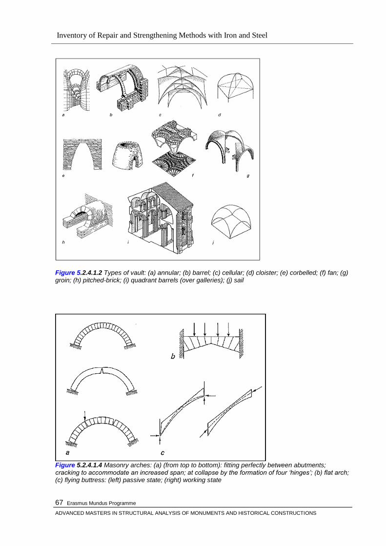
Inventory of Repair and Strengthening Methods with Iron and Steel
Erasmus Mundus Programme
ADVANCED MASTERS IN STRUCTURAL ANALYSIS OF MONUMENTS AND HISTORICAL CONSTRUCTIONS
67
Figure 5.2.4.1.2 Types of vault: (a) annular; (b) barrel; (c) cellular; (d) cloister; (e) corbelled; (f) fan; (g) groin; (h) pitched-brick; (i) quadrant barrels (over galleries); (j) sail
Figure 5.2.4.1.4 Masonry arches: (a) (from top to bottom): fitting perfectly between abutments; cracking to accommodate an increased span; at collapse by the formation of four „hinges‟; (b) flat arch; (c) flying buttress: (left) passive state; (right) working state
Inventory of Repair and Strengthening Methods with Iron and Steel
Erasmus Mundus Programme
ADVANCED MASTERS IN STRUCTURAL ANALYSIS OF MONUMENTS AND HISTORICAL CONSTRUCTIONS
68
Causes of Failures
The master Theorem (the Safe Theorem)
Ideas of a hanging cord, corresponding to the line of thrust in an arch, give a vivid picture of the way in
which such a simple structure behaves. There is, however, a master theorem of masonry, which,
although it applies to any assemblage, no matter how complex, will be presented for the simple arch.
The first inescapable fact is that the system of compressive forces in the structure, equilibrating the
self-weight of the building and carrying wind and other live loads to the ground, must lie completely
within the boundaries of the masonry. The three simplifying assumptions (no tensile strength, great
compressive strength, no slip) enable an account of the behaviour of masonry to be embraced within
the modern so-called plastic theory of structures. The plastic theorems are then available, of which, for
masonry, the ‗safe theorem‘ is the master. The simple statement of the theorem is that if a line of
thrust can be found to lie within the masonry (for example the funicular arch within the real arch), then
the structure can never collapse under the given loads. The statement may seem self-evident, but it
has important consequences.
The power of the safe theorem lies in the fact that the satisfactory thrust line found by the analyst need
not be the actual thrust line, which will necessarily shift as small, unpredictable changes occur in the
environment, causing the structure to respond by a shift in its pattern of cracks. The actual state of a
structure will constantly alter. All the analyst need calculate is just one possible satisfactory state, and
the real structure will also be able to find such a state for itself. There are no conceivable settlements
or other disturbances that can cause the thrusts to shift outside the masonry, as can be seen by
considering in detail some of the consequences of settlement, together with some practical
applications of the safe theorem.
Settlement and Cracking
The five-minute theorem for masonry may be stated for, say, a flying buttress: if the work stands for
five minutes after the timber centering of the flying buttress is removed on completion of the
stonework, then it will stand for 500 years (an upper limit depending on the decay of the material). [33]
This is all that is needed to satisfy the safe theorem by confirming experimentally, on the real
structure, that the shape of the flying buttress is correct. This flamboyant statement assumes that the
loads on the flying buttress are static, arising from self-weight and dead thrusts from the nave vaulting.
It does not necessarily apply to the upper flying buttresses in some large Gothic churches, the function
of which (see Figure 5.2.4.1.5 below) is to resist wind forces acting on the great timber roof; and it
concentrates only on the masonry, ignoring any possible interaction with the foundations, whose
settlement is measured in years, even a decade or so, rather than minutes.
Foundation settlements can lead to geometry changes rather larger than those envisaged so far.
Under the crossing tower of a great church there are almost always indications of gross distortions:
Inventory of Repair and Strengthening Methods with Iron and Steel
Erasmus Mundus Programme
ADVANCED MASTERS IN STRUCTURAL ANALYSIS OF MONUMENTS AND HISTORICAL CONSTRUCTIONS
69
the once horizontal courses of masonry in the nave, choir and transepts abutting a crossing may
indicate settlements of as much as c. 300 mm (now rather more than the thickness of a pencil line on
the drawing board). This is both commonplace and straightforward; the crossing piers, themselves
highly stressed (at one-tenth of the strength of the material), require high bearing stresses from the
soil for their support. The whole of the plan area at the crossing typically requires such a high mean
supporting stress that the modern.
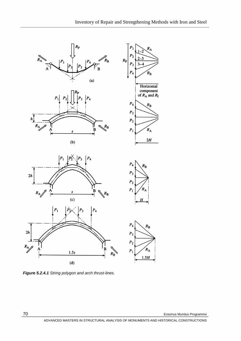
Inventory of Repair and Strengthening Methods with Iron and Steel
Erasmus Mundus Programme
ADVANCED MASTERS IN STRUCTURAL ANALYSIS OF MONUMENTS AND HISTORICAL CONSTRUCTIONS
70
Figure 5.2.4.1 String polygon and arch thrust-lines.
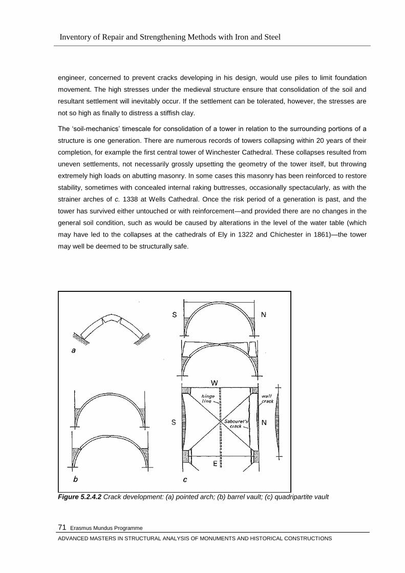
Inventory of Repair and Strengthening Methods with Iron and Steel
Erasmus Mundus Programme
ADVANCED MASTERS IN STRUCTURAL ANALYSIS OF MONUMENTS AND HISTORICAL CONSTRUCTIONS
71
engineer, concerned to prevent cracks developing in his design, would use piles to limit foundation
movement. The high stresses under the medieval structure ensure that consolidation of the soil and
resultant settlement will inevitably occur. If the settlement can be tolerated, however, the stresses are
not so high as finally to distress a stiffish clay.
The ‗soil-mechanics‘ timescale for consolidation of a tower in relation to the surrounding portions of a
structure is one generation. There are numerous records of towers collapsing within 20 years of their
completion, for example the first central tower of Winchester Cathedral. These collapses resulted from
uneven settlements, not necessarily grossly upsetting the geometry of the tower itself, but throwing
extremely high loads on abutting masonry. In some cases this masonry has been reinforced to restore
stability, sometimes with concealed internal raking buttresses, occasionally spectacularly, as with the
strainer arches of c. 1338 at Wells Cathedral. Once the risk period of a generation is past, and the
tower has survived either untouched or with reinforcement—and provided there are no changes in the
general soil condition, such as would be caused by alterations in the level of the water table (which
may have led to the collapses at the cathedrals of Ely in 1322 and Chichester in 1861)—the tower
may well be deemed to be structurally safe.
Figure 5.2.4.2 Crack development: (a) pointed arch; (b) barrel vault; (c) quadripartite vault
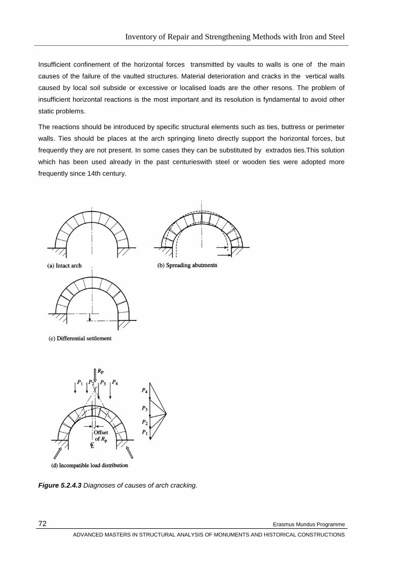
Inventory of Repair and Strengthening Methods with Iron and Steel
Erasmus Mundus Programme
ADVANCED MASTERS IN STRUCTURAL ANALYSIS OF MONUMENTS AND HISTORICAL CONSTRUCTIONS
72
Insufficient confinement of the horizontal forces transmitted by vaults to walls is one of the main
causes of the failure of the vaulted structures. Material deterioration and cracks in the vertical walls
caused by local soil subside or excessive or localised loads are the other resons. The problem of
insufficient horizontal reactions is the most important and its resolution is fyndamental to avoid other
static problems.
The reactions should be introduced by specific structural elements such as ties, buttress or perimeter
walls. Ties should be places at the arch springing lineto directly support the horizontal forces, but
frequently they are not present. In some cases they can be substituted by extrados ties.This solution
which has been used already in the past centurieswith steel or wooden ties were adopted more
frequently since 14th century.
Figure 5.2.4.3 Diagnoses of causes of arch cracking.

Inventory of Repair and Strengthening Methods with Iron and Steel
Erasmus Mundus Programme
ADVANCED MASTERS IN STRUCTURAL ANALYSIS OF MONUMENTS AND HISTORICAL CONSTRUCTIONS
73
All these aspects have been dealt with in great depth by Professor Jacques Heyman in his books The
Masonry Arch (1982) and The Stone Skeleton (1995), in which he quotes Coulomb to the effect that,
if a thrust-line can be constructed that nowhere is closer to the extrados or the intrados than one-tenth
of the thickness of the arch (or vault) the arch will be structurally stable. The edge distance of onetenth
of the thickness was originally stated for Gothic stone masonry arches, where the strength of the stone
is hardly ever critical; for heavily loaded arches, or arches built of soft stone or bricks, the critical edge
distance may have to be increased to, say, one-seventh or one-sixth, to avoid compression failure of
the materials.
All the above assumes that the masonry spandrel panels, and/or the vaults, or any other element,
carried by the arch, have little or no stiffness, nor strength, in the plane of the arch and simply acts as
a load. If, however, the arch merely forms the top of an opening in a large expanse of solid masonry
wall, constructed of large blocks of stone with thin joints of strong mortar, a different mechanism, first
identified by Sir Christopher Wren, can develop.
Figure 5.2.4.4 (a) Wren‟s thrust-free, rigid body arch action; (b) the likely resulting load paths. This mechanism involves some, largely horizontal, tensile forces in the virtual corbels over the arch and the reveals of the opening. In masonry, of the type described above, this would not be a problem, as the shear strength under the preload from the masonry above would be adequate to transfer the horizontal force at a butt joint in one course to the stones in the adjacent ones.
Structural Aspects of Domes
To describe the complex structural behaviour of domes , there are two simplfying assumptions two
simplifying assumptions. Each of them explains a part of the overall behaviour and together they
account for most of the structural strength. The first assumption is that the dome is a ‗shell‘, with a
thickness that is very small relative to its other dimensions. If the basic principles of equilibrium are

Inventory of Repair and Strengthening Methods with Iron and Steel
Erasmus Mundus Programme
ADVANCED MASTERS IN STRUCTURAL ANALYSIS OF MONUMENTS AND HISTORICAL CONSTRUCTIONS
74
applied to a small element of such a shell together with the condition that the shell has no bending
strength (due to its small thickness), a set of differential equations is obtained. These equations look
very off-putting to a person with only elementary mathematics, but if the geometry of the shell is
known, they can be solved and will show how the shell, as a whole, can carry its load.
When such calculations are carried out, it will however be found that whilst there is compression along
the whole of the meridians (the curves following the intersections between the dome surface and
vertical planes through its apex), the circumferential stresses (along the circles formed by the
intersections of horizontal planes with the dome) change from compression to tension when the slope
from horizontal of the surface of the dome reaches a certain value that depends on the shape of the
dome and the distribution of the load (see Fig. 5.2.4.4 a).
Figure 5.2.4.4 Membrane and arch rib action of domes.
Inventory of Repair and Strengthening Methods with Iron and Steel
Erasmus Mundus Programme
ADVANCED MASTERS IN STRUCTURAL ANALYSIS OF MONUMENTS AND HISTORICAL CONSTRUCTIONS
75
For a part-spherical dome with uniform load per unit area of its surface (such as selfweight), the angle
is 51.8°. If a spherical dome has to act as a membrane shell, it therefore has to have a certain tensile
strength in the circumferential direction unless it is rather shallow. It is however possible to shape a
dome, carrying only its self-weight, so that no tension arises. Robert Hooke (cf. Sec. 1.2.1), who
assisted Wren at St Paul‘s Cathedral, arrived (by means of experiments with weighted string
polygons?) at the ideal shape which he called a ‗cubico-parabolic conoid‘. The inner dome of St Paul‘s
spans a diameter of some 32 m and is only two bricks (45 cm) thick. It shows no structural cracks,
despite the explosion of a Second World War bomb in the North Transept and it has no iron ties or
cramps in it. A drawing from the eighteenth century (copied from Wren‘s original?) shows the actual
shape as consisting of three spherical ‗bands‘ with different radii, joining tangentially and ‗flattening‘
towards the top. The absence of structural cracking indicates that the actual shape of the dome is very
close to the ideal theoretical shape, as calculated by Professor Jacques Heyman.
The second, simplifying, assumption abandons the concept of the thin shell and represents the dome
by a series of arch ribs. Each arch rib consists of two opposed ‗orange segments‘ formed by cutting
the dome (with its real thickness) by two vertical planes intersecting at the apex (see Fig. 5.2.4.4b). If it
is possible to construct a thrust-line for the forces acting on one such arch, such that it does not get
closer to either intrados or extrados of the arch than the value appropriate to the material (one-tenth of
the thickness for stone and, say, one-sixth for brick), then each arch is stable and strong enough. If
each arch is stable and strong enough, then clearly the dome is stable and strong enough, even
though it may show cracks along the meridians.
In reality, dome behaviour will usually be a mixture of the two simplified mechanisms, postulated
above: where the slope is less than the one at which the ring force changes from compression to
tension, membrane action is likely to dominate (thus overcoming the objection to the orange-segment
model, that it produces infinite stresses at the apex). Lower down the orange-segment behaviour will
take over, unless the masonry has been reinforced with metal tension rings (and even these will
stretch before developing their force).
Radial cracks in the lower part of a dome are therefore not necessarily a symptom of drastic structural
shortcoming, however unsightly they may appear on the decorations inside, but if they continue to
widen, it is a sign of inadequate horizontal restraint at the base of the dome. This is because, like
arches and vaults, domes require horizontal restraint at their base; this is irrespective of their structural
action being predominantly ‗orange-segment arch‘ or ‗thin shell membrane‘. Like arches and vaults,
domes react to uneven settlement by cracking, but the crack patterns are likely to be more complex.
Repair and Strengthening Techniques
Structural distress in arched structures will usually manifest itself by cracking or opening of joints.
Before any structural intervention is considered, it is however essential to ascertain whether the
cracking is progressing or whether it is static and, if so, if the cause is unlikelyto recur, in which case
only ‗cosmetic‘ repairs are required.

Inventory of Repair and Strengthening Methods with Iron and Steel
Erasmus Mundus Programme
ADVANCED MASTERS IN STRUCTURAL ANALYSIS OF MONUMENTS AND HISTORICAL CONSTRUCTIONS
76
The continuing, increasing, leaning of walls and piers, subject to thrust from arches or vaults, may
have been caused when the original builders misjudged the foundation conditions or got the geometry
of the structure wrong. Alternatively it may be due to later generations having interfered with the
structure or with the surrounding ground. The result is usually a slow spreading of the arches or vaults
with correspondingly increasing tilt of the external walls or piers.
In the case of spreading arches and vaults buttressing is one of the possible technique; an
alternative to buttressing is the provision of ties, which prevent the springings of the arches from
moving apart. Physical ties at springing level are usually architecturally undesirable and it is only on
rare occasions that one can transfer the restraining force to the springings from a tie located at an
invisible or visually unimportant level.
Professor Schultze of Aachen University has provided an example in which tie rods, inserted to
prevent the spreading of the abutments of a Gothic vault, had their mid-points raised above the crown
of the vault by means of a steel roof truss, so as to make them invisible from below the vault.
There has been a number of instances when arches and vaults have been ‗strengthened‘ by being
suspended by grouted-in hanger bars from a concrete structure built above (and in many cases right
on top of) the original masonry structure. The attraction of such an arrangement is that the concrete
relieving structure can be designed and built to conform today‘s codes of practice, thus circumventing
the ambiguities in the original construction, e.g. if sufficient buttressing is not available, the relieving
structure can be made to act as a beam.
Such interventions preserve the appearance of the underside of the arch or vault, but change the
function from structural to merely decorative. They should therefore be considered as a last resort,
particularly when they involve casting or spraying the concrete directly on to the masonry, as in that
case the intervention becomes irreversible. If provision of such an overlay structure, after careful
consideration, is found to be the only solution, a separation membrane e.g. polyethylene sheeting
should be used.
The shape of horizontal sections through domes, whether polygonal or circular, can make it relatively
easy to provide additional circumferential strength and/or horizontal base restraint; removal of the roof
cladding and a small thickness of the masonry will enable the insertion of a tension ring. As a single
steel rod or cable may cause too high bearing stresses and hence tend to ‗cut‘ into the masonry
(especially if this is of soft brick), a number of smaller bars or cables should be used together with
spreaders along meridians. Such hardware must be adequately protected against ingress of rainwater,
unless stainless steel or nonferrous alloys are used. If space permits, reinforced concrete ring beams
may be used, preferably with a separation membrane to facilitate a future renewal or removal, so that
reversibility of the intervention is made easier.
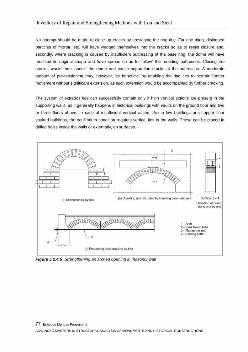
Inventory of Repair and Strengthening Methods with Iron and Steel
Erasmus Mundus Programme
ADVANCED MASTERS IN STRUCTURAL ANALYSIS OF MONUMENTS AND HISTORICAL CONSTRUCTIONS
77
No attempt should be made to close up cracks by tensioning the ring ties. For one thing, dislodged
particles of mortar, etc. will have wedged themselves into the cracks so as to resist closure and,
secondly, where cracking is caused by insufficient buttressing of the base ring, the dome will have
modified its original shape and have spread so as to ‗follow‘ the receding buttresses. Closing the
cracks, would then ‗shrink‘ the dome and cause separation cracks at the buttresses. A moderate
amount of pre-tensioning may, however, be beneficial by enabling the ring ties to restrain further
movement without significant extension, as such extension would be accompanied by further cracking.
The system of extrados ties can successfully contain only if high vertical actions are present in the
supporting walls, as it generally happens in historical buildings with vaults on the ground floor and two
or three floors above. In case of insufficient vertical action, like in low buildings or in upper floor
vaulted buildings, the equilibrium condition requires vertical ties in the walls. These can be placed in
drilled holes inside the walls or externally, on surfaces.
Figure 5.2.4.5 Strengthening an arched opening in masonry wall
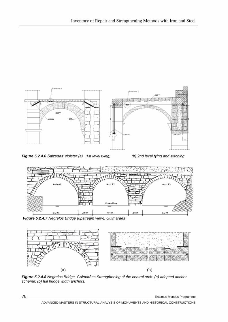
Inventory of Repair and Strengthening Methods with Iron and Steel
Erasmus Mundus Programme
ADVANCED MASTERS IN STRUCTURAL ANALYSIS OF MONUMENTS AND HISTORICAL CONSTRUCTIONS
78
Figure 5.2.4.6 Salzedas‟ cloister (a) 1st level tying; (b) 2nd level tying and stitching
Figure 5.2.4.7 Negrelos Bridge (upstream view), Guimarães
Figure 5.2.4.8 Negrelos Bridge, Guimarães Strengthening of the central arch: (a) adopted anchor scheme; (b) full bridge width anchors.

Inventory of Repair and Strengthening Methods with Iron and Steel
Erasmus Mundus Programme
ADVANCED MASTERS IN STRUCTURAL ANALYSIS OF MONUMENTS AND HISTORICAL CONSTRUCTIONS
79
To prevent any additional increase of the longitudinal cracking in the intrados of the central arch as
well as to assure its future stability, a set of four horizontal stainless steel anchors across the full
bridge width, endowed with cylindrical steel anchorage plates at each side of the arch, were proposed,
see Figure 5.2.4.8 above. Also, two additional shorter stainless steel anchors were used close to
each springing. In addition, it was recommended a light injection of the arch, at the intrados. For the
connection between the arch and the spandrel walls a similar solution was developed. Five stitching
anchors in each side of the arch were used with the purpose of linking the spandrel walls to the
external arch voussoirs, see Figure 5.2.4.8a. In order to face the out-of-plumbness of the spandrel
walls above the left arch, it was decided to use two horizontal stainless steel anchors across the full
bridge width provided with cross-shaped anchorage plates at the extremes. The shape of the plates
was due to aesthetic reasons.
To repair the high level of damage found in the downstream cutwaters, with some stones cracked and
others out of their original place and disconnected from the piers, the dismantling and subsequent
rebuilding of the most deteriorated areas was proposed. On the other hand, the upstream cutwaters,
less damaged but also in a poor condition, are to be injected with a lime-based grout after conclusion
of the joint repointing works. All infesting vegetation is to be removed using the most adequate
procedures, and all masonry joints that show degradation are to be carefully cleaned and repointed. In
order to prevent the fines from being washed out of the fill material, leading to voids and thus affecting
the carrying capacity of the bridge, it was recommended the execution of an adequate waterproofing
and drainage of the pavement.
5.2.4 Bed joint Reinforcement Technique
General
The mechanical properties and the behaviour of masonry depend strongly on the orientation of the
bed joints towards the applied load and the stress state of the joints.
The bed joint reinforcement technique is based on the insertion of steel bars in the mortar bed joints
previously excavated for few centimeters and then refilled by a repointing material. It is particularly
applicable to facing masonry having regular courses (e.g., brick or stone masonry rather than rubble
stone walls), where it can be appropriate for several structural conditions.
High compression loads, often characterizing massive brick masonry structures such as towers,
curtain walls and heavily loaded pillars, can lead to critical conditions due to the activation ofcreep
(Fig. 5.2.5.1) .Typical damage—vertical and sub-vertical; thin, but very diffuse cracks—is worsened by
cyclic stresses (due to thermal and hygroscopic strains) or low dynamic forces (windaction or bell
ringing), and can affect bricks even in a large portion of the wall thickness [26]. This type of damage,
generally disregarded in such structures, in comparison with other, more evident, critical conditions
(large cracks, out-ofplumb,
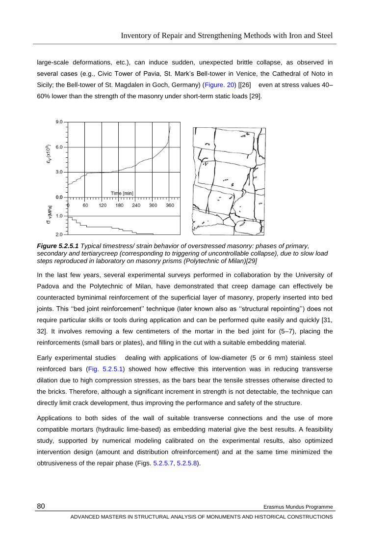
Inventory of Repair and Strengthening Methods with Iron and Steel
Erasmus Mundus Programme
ADVANCED MASTERS IN STRUCTURAL ANALYSIS OF MONUMENTS AND HISTORICAL CONSTRUCTIONS
80
large-scale deformations, etc.), can induce sudden, unexpected brittle collapse, as observed in
several cases (e.g., Civic Tower of Pavia, St. Mark‘s Bell-tower in Venice, the Cathedral of Noto in
Sicily; the Bell-tower of St. Magdalen in Goch, Germany) (Figure. 20) [[26] even at stress values 40–
60% lower than the strength of the masonry under short-term static loads [29].
Figure 5.2.5.1 Typical timestress/ strain behavior of overstressed masonry: phases of primary, secondary and tertiarycreep (corresponding to triggering of uncontrollable collapse), due to slow load steps reproduced in laboratory on masonry prisms (Polytechnic of Milan)[29]
In the last few years, several experimental surveys performed in collaboration by the University of
Padova and the Polytechnic of Milan, have demonstrated that creep damage can effectively be
counteracted byminimal reinforcement of the superficial layer of masonry, properly inserted into bed
joints. This ‗‗bed joint reinforcement‘‘ technique (later known also as ‗‗structural repointing‘‘) does not
require particular skills or tools during application and can be performed quite easily and quickly [31,
32]. It involves removing a few centimeters of the mortar in the bed joint for (5–7), placing the
reinforcements (small bars or plates), and filling in the cut with a suitable embedding material.
Early experimental studies dealing with applications of low-diameter (5 or 6 mm) stainless steel
reinforced bars (Fig. 5.2.5.1) showed how effective this intervention was in reducing transverse
dilation due to high compression stresses, as the bars bear the tensile stresses otherwise directed to
the bricks. Therefore, although a significant increment in strength is not detectable, the technique can
directly limit crack development, thus improving the performance and safety of the structure.
Applications to both sides of the wall of suitable transverse connections and the use of more
compatible mortars (hydraulic lime-based) as embedding material give the best results. A feasibility
study, supported by numerical modeling calibrated on the experimental results, also optimized
intervention design (amount and distribution ofreinforcement) and at the same time minimized the
obtrusiveness of the repair phase (Figs. 5.2.5.7, 5.2.5.8).
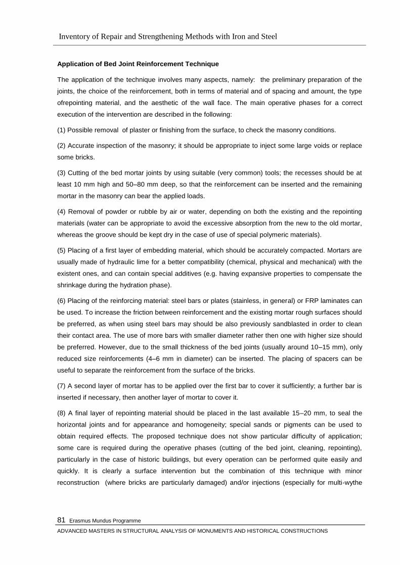
Inventory of Repair and Strengthening Methods with Iron and Steel
Erasmus Mundus Programme
ADVANCED MASTERS IN STRUCTURAL ANALYSIS OF MONUMENTS AND HISTORICAL CONSTRUCTIONS
81
Application of Bed Joint Reinforcement Technique
The application of the technique involves many aspects, namely: the preliminary preparation of the
joints, the choice of the reinforcement, both in terms of material and of spacing and amount, the type
ofrepointing material, and the aesthetic of the wall face. The main operative phases for a correct
execution of the intervention are described in the following:
(1) Possible removal of plaster or finishing from the surface, to check the masonry conditions.
(2) Accurate inspection of the masonry; it should be appropriate to inject some large voids or replace
some bricks.
(3) Cutting of the bed mortar joints by using suitable (very common) tools; the recesses should be at
least 10 mm high and 50–80 mm deep, so that the reinforcement can be inserted and the remaining
mortar in the masonry can bear the applied loads.
(4) Removal of powder or rubble by air or water, depending on both the existing and the repointing
materials (water can be appropriate to avoid the excessive absorption from the new to the old mortar,
whereas the groove should be kept dry in the case of use of special polymeric materials).
(5) Placing of a first layer of embedding material, which should be accurately compacted. Mortars are
usually made of hydraulic lime for a better compatibility (chemical, physical and mechanical) with the
existent ones, and can contain special additives (e.g. having expansive properties to compensate the
shrinkage during the hydration phase).
(6) Placing of the reinforcing material: steel bars or plates (stainless, in general) or FRP laminates can
be used. To increase the friction between reinforcement and the existing mortar rough surfaces should
be preferred, as when using steel bars may should be also previously sandblasted in order to clean
their contact area. The use of more bars with smaller diameter rather then one with higher size should
be preferred. However, due to the small thickness of the bed joints (usually around 10–15 mm), only
reduced size reinforcements (4–6 mm in diameter) can be inserted. The placing of spacers can be
useful to separate the reinforcement from the surface of the bricks.
(7) A second layer of mortar has to be applied over the first bar to cover it sufficiently; a further bar is
inserted if necessary, then another layer of mortar to cover it.
(8) A final layer of repointing material should be placed in the last available 15–20 mm, to seal the
horizontal joints and for appearance and homogeneity; special sands or pigments can be used to
obtain required effects. The proposed technique does not show particular difficulty of application;
some care is required during the operative phases (cutting of the bed joint, cleaning, repointing),
particularly in the case of historic buildings, but every operation can be performed quite easily and
quickly. It is clearly a surface intervention but the combination of this technique with minor
reconstruction (where bricks are particularly damaged) and/or injections (especially for multi-wythe
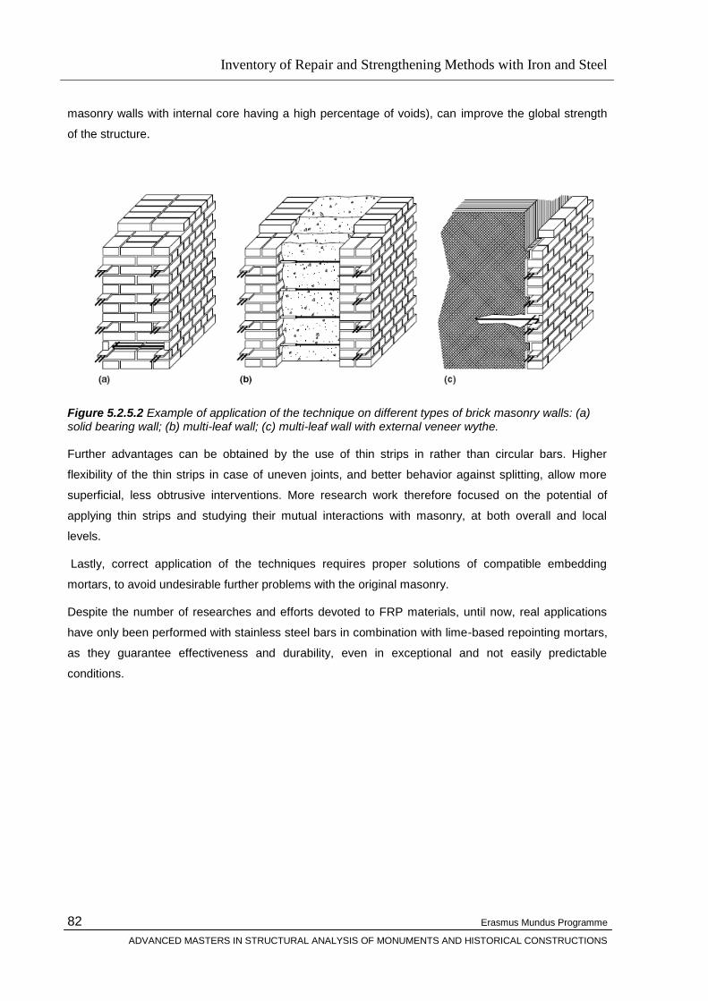
Inventory of Repair and Strengthening Methods with Iron and Steel
Erasmus Mundus Programme
ADVANCED MASTERS IN STRUCTURAL ANALYSIS OF MONUMENTS AND HISTORICAL CONSTRUCTIONS
82
masonry walls with internal core having a high percentage of voids), can improve the global strength
of the structure.
Figure 5.2.5.2 Example of application of the technique on different types of brick masonry walls: (a) solid bearing wall; (b) multi-leaf wall; (c) multi-leaf wall with external veneer wythe. Further advantages can be obtained by the use of thin strips in rather than circular bars. Higher
flexibility of the thin strips in case of uneven joints, and better behavior against splitting, allow more
superficial, less obtrusive interventions. More research work therefore focused on the potential of
applying thin strips and studying their mutual interactions with masonry, at both overall and local
levels.
Lastly, correct application of the techniques requires proper solutions of compatible embedding
mortars, to avoid undesirable further problems with the original masonry.
Despite the number of researches and efforts devoted to FRP materials, until now, real applications
have only been performed with stainless steel bars in combination with lime-based repointing mortars,
as they guarantee effectiveness and durability, even in exceptional and not easily predictable
conditions.
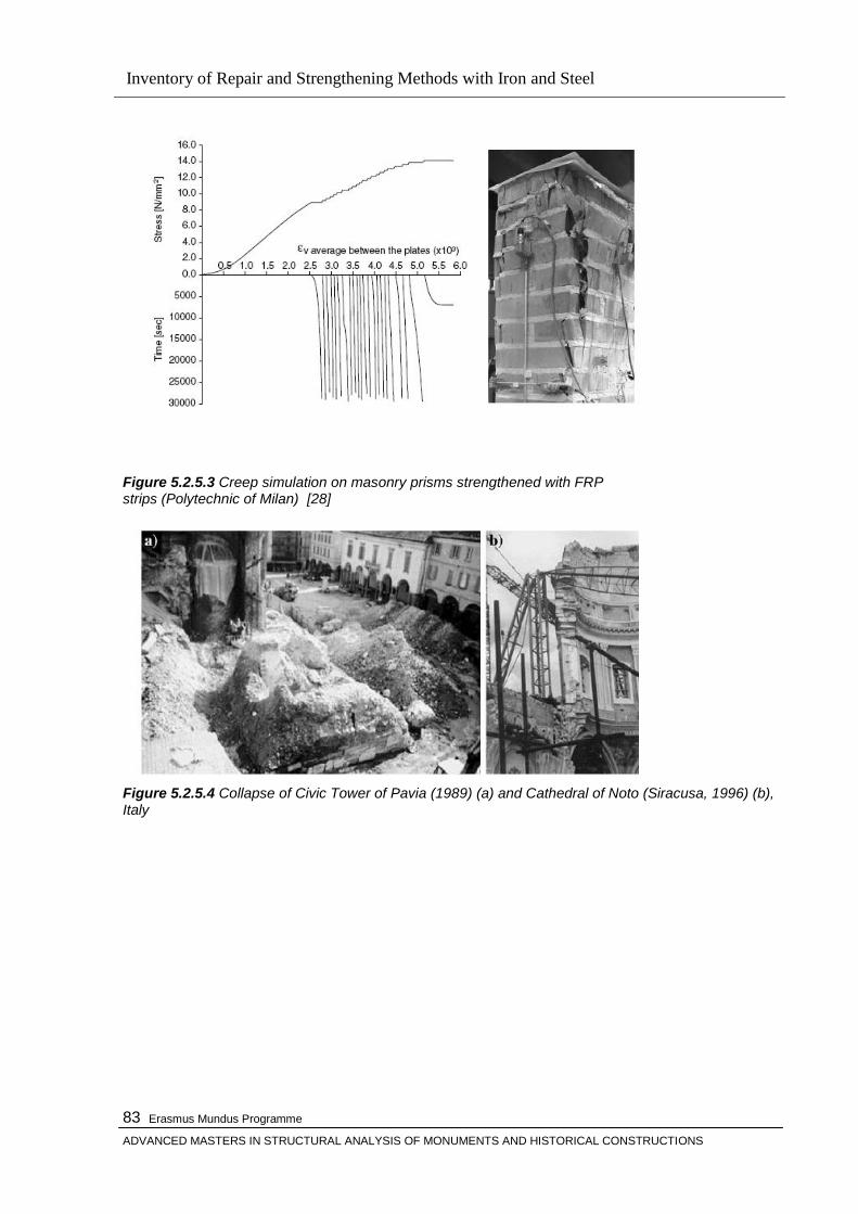
Inventory of Repair and Strengthening Methods with Iron and Steel
Erasmus Mundus Programme
ADVANCED MASTERS IN STRUCTURAL ANALYSIS OF MONUMENTS AND HISTORICAL CONSTRUCTIONS
83
Figure 5.2.5.3 Creep simulation on masonry prisms strengthened with FRP strips (Polytechnic of Milan) [28]
Figure 5.2.5.4 Collapse of Civic Tower of Pavia (1989) (a) and Cathedral of Noto (Siracusa, 1996) (b), Italy

Inventory of Repair and Strengthening Methods with Iron and Steel
Erasmus Mundus Programme
ADVANCED MASTERS IN STRUCTURAL ANALYSIS OF MONUMENTS AND HISTORICAL CONSTRUCTIONS
84
Figure 5.2.5.5Experimental study of interface behavior of CFRP strips and numerical simulation,
showing stress migration along anchoring length and influence of rectangular section in limiting
mortar splitting (due to elliptical stress distribution around strip) [27]
Experimental validation of the performance [26] of the bed reinforcement technique means that it may
be proposed for the consolidation of several ancient constructions and monuments at risk ,
counteracting dilation under high compressive stress by improving material toughness. Note that, in
real cases, several types of damage may co-exist, so that proper selection and combinations of
various intervention techniques should be considered. In many cases, both injections and partial,
limited rebuilding (the tradi-tional ‗‗scuci-cuci‘‘) are used, to reduce stress concentration and to replace
the most severely damaged parts, respectively.
These techniques act locally by improving the mechanical behavior of the material, thus contributing to
rehabilitation of the proper loadbearing capacity of the structure.
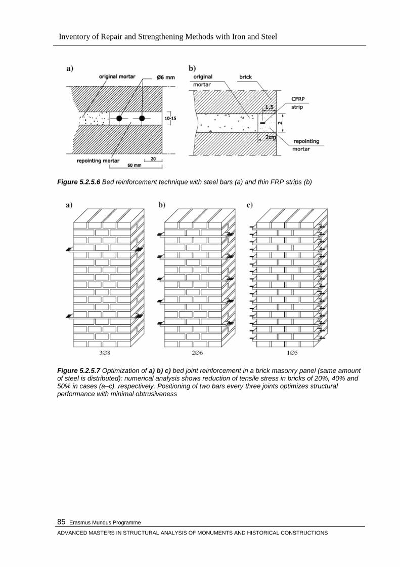
Inventory of Repair and Strengthening Methods with Iron and Steel
Erasmus Mundus Programme
ADVANCED MASTERS IN STRUCTURAL ANALYSIS OF MONUMENTS AND HISTORICAL CONSTRUCTIONS
85
Figure 5.2.5.6 Bed reinforcement technique with steel bars (a) and thin FRP strips (b)
Figure 5.2.5.7 Optimization of a) b) c) bed joint reinforcement in a brick masonry panel (same amount of steel is distributed): numerical analysis shows reduction of tensile stress in bricks of 20%, 40% and 50% in cases (a–c), respectively. Positioning of two bars every three joints optimizes structural performance with minimal obtrusiveness

Inventory of Repair and Strengthening Methods with Iron and Steel
Erasmus Mundus Programme
ADVANCED MASTERS IN STRUCTURAL ANALYSIS OF MONUMENTS AND HISTORICAL CONSTRUCTIONS
86
Figur 5.2.5.8 Example of panels strengthened with various types of reinforcement: (a) steel bars; (b) circular CFRP bars (anchoring in short sides with metal sleeves); (c) thin CFRP strips (no overlap at corner, unless specially designed elements are available)
Figure 5.2.5.9 Example of panels strengthened with various types of reinforcement: (a) steel bars; (b) circular CFRP bars (anchoring in short sides with metal sleeves); (c) thin CFRP strips (no overlap at corner, unless specially designed elements are available)

Inventory of Repair and Strengthening Methods with Iron and Steel
Erasmus Mundus Programme
ADVANCED MASTERS IN STRUCTURAL ANALYSIS OF MONUMENTS AND HISTORICAL CONSTRUCTIONS
87
Figure 5.2.5.10 On-site insertion of reinforced bars into joints Figure 5.2.5.11 and 5.12 show the intervention works carried out upon the determination of hazardous
cond,t,ons found in some of the pillars of the church of S. Sofia, Padova, Italy [26]. Several cracks
were detected, and steel reinforcement rings, together with injections and local rebuilding, were
provisionally placed in some portions of the structure. All the sides of the pillars have been
strengthened with the bed joint reinforce-
Figure 5.2.5.11 Church of S. Sofia in Padova: provisional measures on cracked pillars
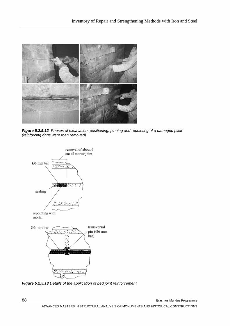
Inventory of Repair and Strengthening Methods with Iron and Steel
Erasmus Mundus Programme
ADVANCED MASTERS IN STRUCTURAL ANALYSIS OF MONUMENTS AND HISTORICAL CONSTRUCTIONS
88
Figure 5.2.5.12 Phases of excavation, positioning, pinning and repointing of a damaged pillar (reinforcing rings were then removed)
Figure 5.2.5.13 Details of the application of bed joint reinforcement

Inventory of Repair and Strengthening Methods with Iron and Steel
Erasmus Mundus Programme
ADVANCED MASTERS IN STRUCTURAL ANALYSIS OF MONUMENTS AND HISTORICAL CONSTRUCTIONS
89
5.2.6 Seismic Retrofitting of Unreinforced Masonry with Metallic or Different Material Tie-Rods
Many experiences in restoration and rehabilitation of damaged masonry buildings have been carried
out in Italy during more than fifty years; in many cases the interventions were performed after a long
period of misuse and lack of maintenance following the second world war. During this period also
major earthquakes have taken place in most of the Mediterranean countries [40] . Unreinforced
masonry buildings are characterized by their vulnerability to the seismic action being . Especially in
historic centers, having subjected to non homogeneous constructive phases due to extensions
occurred in the past by merging parts or superimposing new ones the inadequate connection of parts
through excessively slender elements can result in overturning mechanisms when subjected to
seismic lateral loading. The study of the building rules and structural details, such as the wall sections,
has a great importance in the mechanic behaviour of a building. As an example, historic stonemasonry
buildings present a peculiar structural and durability behaviour which is different from the one of the
brick-masonry buildings [Giuffrè, 1991], [Giuffrè, 1993].
Figure 5.2.6.1 Damages after Umbria earthquake to a building repaired by introduction of concrete tie beams.

Inventory of Repair and Strengthening Methods with Iron and Steel
Erasmus Mundus Programme
ADVANCED MASTERS IN STRUCTURAL ANALYSIS OF MONUMENTS AND HISTORICAL CONSTRUCTIONS
90
The severe damages suffered by URM buildings which were repaired and strengthened after recent
earthquakes in Italy, have proved the inadequacy of the retrofitting strategies and techniques adopted
in the last thirty years. Examples of inadequate interventions have been given by the introduction of
additional reinforced concrete elements in the form of rigid diaphragm, r.c. ring beams, columns
inserted within the depth of the walls without specific attention to the effects of an increased level of
mass and stiffness. Unexpected local or global failure mechanisms due to the enforced deformation
incompatibilities with the original structures could result. These issues opened a wide cultural debate,
exacerbated by a strong public opinion reaction after the Molise Earthquake event in 2002, where the
partial collapse of a primary public school caused the decease of twenty seven children. As a result, a
new seismic hazard zonation was approved along with the development of a new seismic code
(OPCM 3431/05), issued by the Italian Civil Protection Department In particular, a special Annex 11E
has been included specifically focussed to the description of alternative feasible retrofit and
strengthening techniques for Unreinforced Masonry Buildings. The different proposed solutions have
been subdivided based on their targeted performance objective, while highlighting limits and positive
features of each solution also depending on the masonry typology.
Retrofitting Interventions
The performance of a building subject to an earthquake motions is governed by the inter-connectivity
between structural components as well as the individual component's strength, stiffness and ductility.
When separate components of the structural system are strengthened care should be taken to ensure
uniform distribution of lateral stiffness in both directions in plan. When constructing additional
structural elements, for example new RC columns or RC shear wall between columns these should
also allow for uniform distribution of stiffness in plan and in elevation. Rules for horizontal and vertical
regularity should be followed when strengthening the original structure. Below are listed rules that
should be followed to achieve satisfactory repair:
The structural walls should be uniformly distributed in both directions in plan.
The number of walls and their cross section dimensions are based on the seismic resistance
design. The structural walls should be bonded together and tied to ensure common action
Floors should be capable of rigid diaphragm action.
Floors should be connected to structural walls by means of steel ties to provide restraint at top
of walls against out-of-plane vibration
The foundations must be strengthened as well to ensure adequate load transfer to the soils.
In cases where RC shear walls are being added to the structure their foundations should be
carefully detailed and constructed
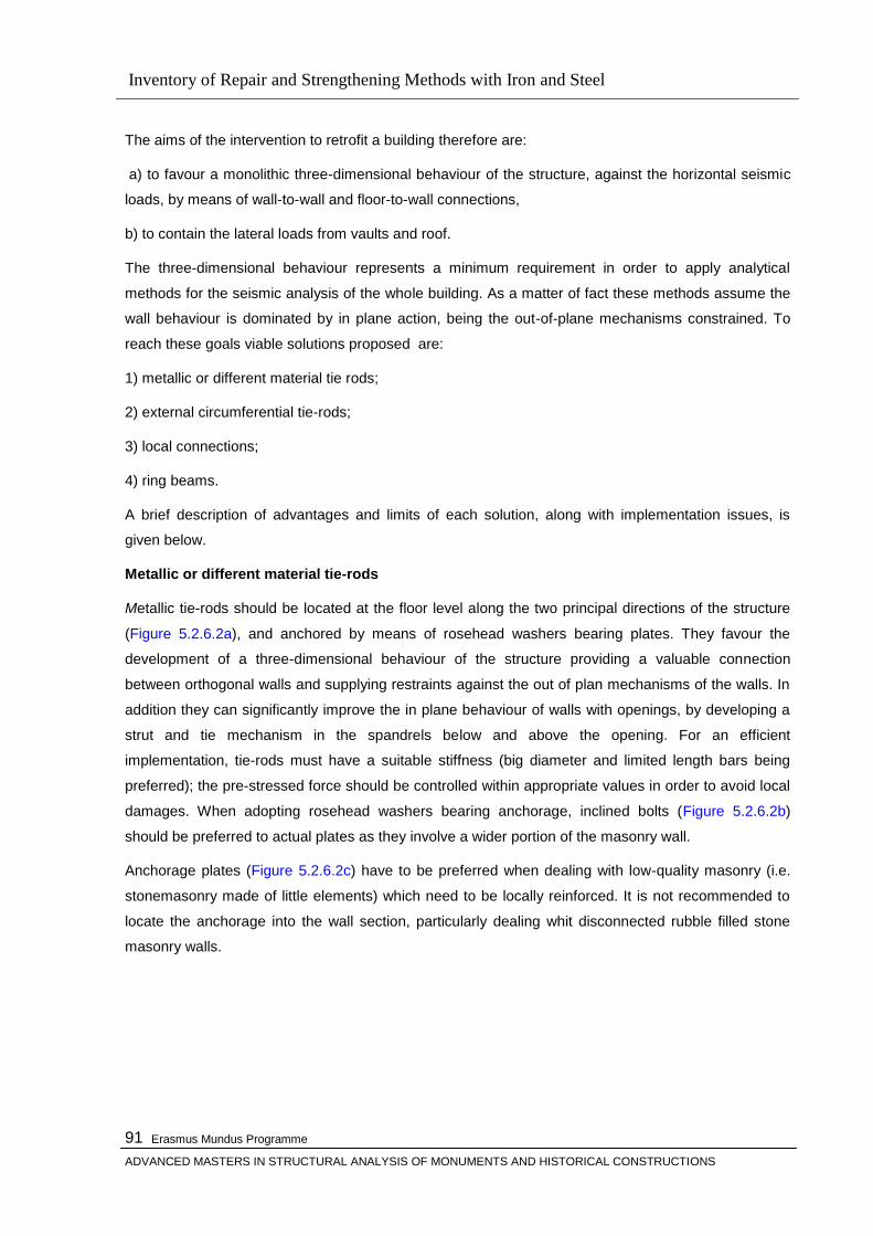
Inventory of Repair and Strengthening Methods with Iron and Steel
Erasmus Mundus Programme
ADVANCED MASTERS IN STRUCTURAL ANALYSIS OF MONUMENTS AND HISTORICAL CONSTRUCTIONS
91
The aims of the intervention to retrofit a building therefore are:
a) to favour a monolithic three-dimensional behaviour of the structure, against the horizontal seismic
loads, by means of wall-to-wall and floor-to-wall connections,
b) to contain the lateral loads from vaults and roof.
The three-dimensional behaviour represents a minimum requirement in order to apply analytical
methods for the seismic analysis of the whole building. As a matter of fact these methods assume the
wall behaviour is dominated by in plane action, being the out-of-plane mechanisms constrained. To
reach these goals viable solutions proposed are:
1) metallic or different material tie rods;
2) external circumferential tie-rods;
3) local connections;
4) ring beams.
A brief description of advantages and limits of each solution, along with implementation issues, is
given below.
Metallic or different material tie-rods
Metallic tie-rods should be located at the floor level along the two principal directions of the structure
(Figure 5.2.6.2a), and anchored by means of rosehead washers bearing plates. They favour the
development of a three-dimensional behaviour of the structure providing a valuable connection
between orthogonal walls and supplying restraints against the out of plan mechanisms of the walls. In
addition they can significantly improve the in plane behaviour of walls with openings, by developing a
strut and tie mechanism in the spandrels below and above the opening. For an efficient
implementation, tie-rods must have a suitable stiffness (big diameter and limited length bars being
preferred); the pre-stressed force should be controlled within appropriate values in order to avoid local
damages. When adopting rosehead washers bearing anchorage, inclined bolts (Figure 5.2.6.2b)
should be preferred to actual plates as they involve a wider portion of the masonry wall.
Anchorage plates (Figure 5.2.6.2c) have to be preferred when dealing with low-quality masonry (i.e.
stonemasonry made of little elements) which need to be locally reinforced. It is not recommended to
locate the anchorage into the wall section, particularly dealing whit disconnected rubble filled stone
masonry walls.
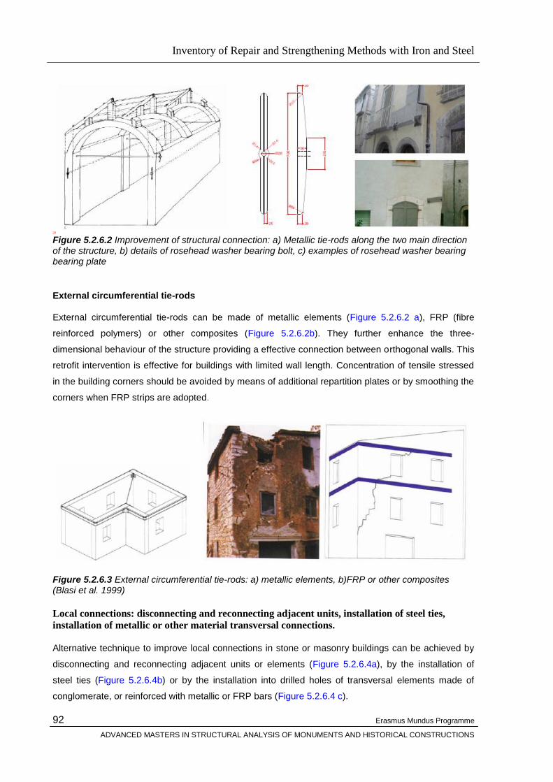
Inventory of Repair and Strengthening Methods with Iron and Steel
Erasmus Mundus Programme
ADVANCED MASTERS IN STRUCTURAL ANALYSIS OF MONUMENTS AND HISTORICAL CONSTRUCTIONS
92
28 Figure 5.2.6.2 Improvement of structural connection: a) Metallic tie-rods along the two main direction of the structure, b) details of rosehead washer bearing bolt, c) examples of rosehead washer bearing bearing plate
External circumferential tie-rods
External circumferential tie-rods can be made of metallic elements (Figure 5.2.6.2 a), FRP (fibre
reinforced polymers) or other composites (Figure 5.2.6.2b). They further enhance the three-
dimensional behaviour of the structure providing a effective connection between orthogonal walls. This
retrofit intervention is effective for buildings with limited wall length. Concentration of tensile stressed
in the building corners should be avoided by means of additional repartition plates or by smoothing the
corners when FRP strips are adopted.
Figure 5.2.6.3 External circumferential tie-rods: a) metallic elements, b)FRP or other composites (Blasi et al. 1999)
Local connections: disconnecting and reconnecting adjacent units, installation of steel ties,
installation of metallic or other material transversal connections.
Alternative technique to improve local connections in stone or masonry buildings can be achieved by
disconnecting and reconnecting adjacent units or elements (Figure 5.2.6.4a), by the installation of
steel ties (Figure 5.2.6.4b) or by the installation into drilled holes of transversal elements made of
conglomerate, or reinforced with metallic or FRP bars (Figure 5.2.6.4 c).
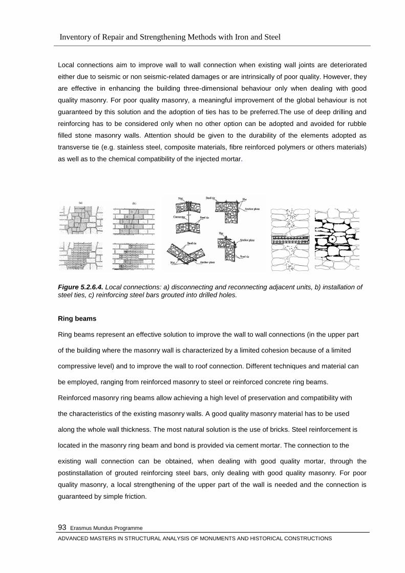
Inventory of Repair and Strengthening Methods with Iron and Steel
Erasmus Mundus Programme
ADVANCED MASTERS IN STRUCTURAL ANALYSIS OF MONUMENTS AND HISTORICAL CONSTRUCTIONS
93
Local connections aim to improve wall to wall connection when existing wall joints are deteriorated
either due to seismic or non seismic-related damages or are intrinsically of poor quality. However, they
are effective in enhancing the building three-dimensional behaviour only when dealing with good
quality masonry. For poor quality masonry, a meaningful improvement of the global behaviour is not
guaranteed by this solution and the adoption of ties has to be preferred.The use of deep drilling and
reinforcing has to be considered only when no other option can be adopted and avoided for rubble
filled stone masonry walls. Attention should be given to the durability of the elements adopted as
transverse tie (e.g. stainless steel, composite materials, fibre reinforced polymers or others materials)
as well as to the chemical compatibility of the injected mortar.
Figure 5.2.6.4. Local connections: a) disconnecting and reconnecting adjacent units, b) installation of steel ties, c) reinforcing steel bars grouted into drilled holes.
Ring beams
Ring beams represent an effective solution to improve the wall to wall connections (in the upper part
of the building where the masonry wall is characterized by a limited cohesion because of a limited
compressive level) and to improve the wall to roof connection. Different techniques and material can
be employed, ranging from reinforced masonry to steel or reinforced concrete ring beams.
Reinforced masonry ring beams allow achieving a high level of preservation and compatibility with
the characteristics of the existing masonry walls. A good quality masonry material has to be used
along the whole wall thickness. The most natural solution is the use of bricks. Steel reinforcement is
located in the masonry ring beam and bond is provided via cement mortar. The connection to the
existing wall connection can be obtained, when dealing with good quality mortar, through the
postinstallation of grouted reinforcing steel bars, only dealing with good quality masonry. For poor
quality masonry, a local strengthening of the upper part of the wall is needed and the connection is
guaranteed by simple friction.

Inventory of Repair and Strengthening Methods with Iron and Steel
Erasmus Mundus Programme
ADVANCED MASTERS IN STRUCTURAL ANALYSIS OF MONUMENTS AND HISTORICAL CONSTRUCTIONS
94
Steel ring beams (Figure 5.2.6.5) represent a valid alternative to the previously proposed solution,
thanks to their lightness, limited invasiveness and the fact that they allow proper connections with the
timber elements of the roof (possibly limiting their horizontal loads). They can be realized employing a
steel truss made of steel angle or plates or placing steel plates on the inner and outer sides of the
wall, connected through transverse threaded bars or rods. A satisfactory connection to the wall can be
achieved in either case without the use of post-installed bars. A local strengthening of the masonry
wall is still required when dealing with poor quality masonry. An effective variation to the previous
proposed solution, is to locate the steel ring-beam on both sides of rather then at the top of the wall.
In this way the intervention can be implemented without the need to remove the existing roof, to
demolish the upper part of the wall, or to increase the roof level. Moreover, in this configuration the
masonry wall is more stable with respect to the upper part, thanks to the contribution of the vertical
load from the roof. The lateral ring beam can be realized by a double steel truss structure (both on the
inner and outer side of the wall) welded together directly on site in order to minimize issues related to
geometrical irregularities, The connection between the inner and outer lateral steel ring beams will be
guaranteed through drilled and grouted bars/rods.
Reinforced concrete ring beams can be realized only if limited in height, in order to avoid excessive
increase in weight and stiffness as well as in tangential stresses between the ring beam and the wall,
which could lead to sliding of the ring beam and desegregation of the masonry wall. Because of the
difference in stiffness between masonry and reinforced concrete element, a local strengthening of the
upper part of the wall can be in any case required. The connection to the wall can be improved by
using post-installed grouted bars/rods.
Figure 5.2.6.5 Steel ring beam: a) connection between the wood roof element and the walls; b,c) partial strengthening of the plywood panel diaphragm and its connection with the steel ring beams (Regione Marche 2000).
An effective connection between the horizontal slab and the ring beam has to be obtained in order to
avoid sliding of the wooden slab beams and the consequent collapse of the slab. The connection
between ring-beam and wall allows, moreover, for a better distribution of the horizontal seismic load
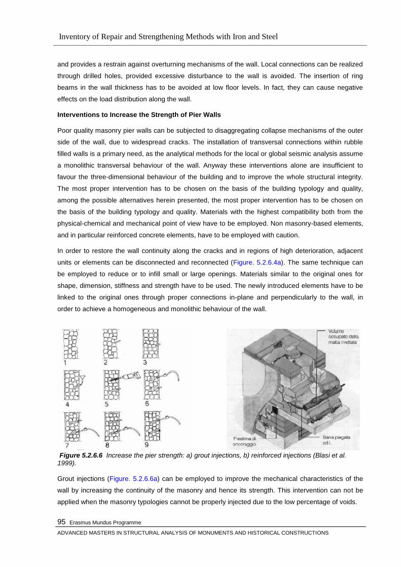
Inventory of Repair and Strengthening Methods with Iron and Steel
Erasmus Mundus Programme
ADVANCED MASTERS IN STRUCTURAL ANALYSIS OF MONUMENTS AND HISTORICAL CONSTRUCTIONS
95
and provides a restrain against overturning mechanisms of the wall. Local connections can be realized
through drilled holes, provided excessive disturbance to the wall is avoided. The insertion of ring
beams in the wall thickness has to be avoided at low floor levels. In fact, they can cause negative
effects on the load distribution along the wall.
Interventions to Increase the Strength of Pier Walls
Poor quality masonry pier walls can be subjected to disaggregating collapse mechanisms of the outer
side of the wall, due to widespread cracks. The installation of transversal connections within rubble
filled walls is a primary need, as the analytical methods for the local or global seismic analysis assume
a monolithic transversal behaviour of the wall. Anyway these interventions alone are insufficient to
favour the three-dimensional behaviour of the building and to improve the whole structural integrity.
The most proper intervention has to be chosen on the basis of the building typology and quality,
among the possible alternatives herein presented, the most proper intervention has to be chosen on
the basis of the building typology and quality. Materials with the highest compatibility both from the
physical-chemical and mechanical point of view have to be employed. Non masonry-based elements,
and in particular reinforced concrete elements, have to be employed with caution.
In order to restore the wall continuity along the cracks and in regions of high deterioration, adjacent
units or elements can be disconnected and reconnected (Figure. 5.2.6.4a). The same technique can
be employed to reduce or to infill small or large openings. Materials similar to the original ones for
shape, dimension, stiffness and strength have to be used. The newly introduced elements have to be
linked to the original ones through proper connections in-plane and perpendicularly to the wall, in
order to achieve a homogeneous and monolithic behaviour of the wall.
Figure 5.2.6.6 Increase the pier strength: a) grout injections, b) reinforced injections (Blasi et al. 1999). Grout injections (Figure. 5.2.6.6a) can be employed to improve the mechanical characteristics of the
wall by increasing the continuity of the masonry and hence its strength. This intervention can not be
applied when the masonry typologies cannot be properly injected due to the low percentage of voids.
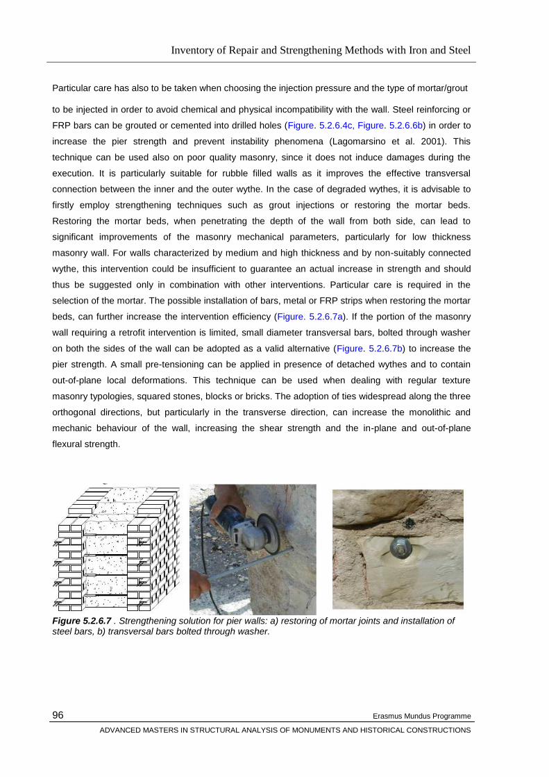
Inventory of Repair and Strengthening Methods with Iron and Steel
Erasmus Mundus Programme
ADVANCED MASTERS IN STRUCTURAL ANALYSIS OF MONUMENTS AND HISTORICAL CONSTRUCTIONS
96
Particular care has also to be taken when choosing the injection pressure and the type of mortar/grout
to be injected in order to avoid chemical and physical incompatibility with the wall. Steel reinforcing or
FRP bars can be grouted or cemented into drilled holes (Figure. 5.2.6.4c, Figure. 5.2.6.6b) in order to
increase the pier strength and prevent instability phenomena (Lagomarsino et al. 2001). This
technique can be used also on poor quality masonry, since it does not induce damages during the
execution. It is particularly suitable for rubble filled walls as it improves the effective transversal
connection between the inner and the outer wythe. In the case of degraded wythes, it is advisable to
firstly employ strengthening techniques such as grout injections or restoring the mortar beds.
Restoring the mortar beds, when penetrating the depth of the wall from both side, can lead to
significant improvements of the masonry mechanical parameters, particularly for low thickness
masonry wall. For walls characterized by medium and high thickness and by non-suitably connected
wythe, this intervention could be insufficient to guarantee an actual increase in strength and should
thus be suggested only in combination with other interventions. Particular care is required in the
selection of the mortar. The possible installation of bars, metal or FRP strips when restoring the mortar
beds, can further increase the intervention efficiency (Figure. 5.2.6.7a). If the portion of the masonry
wall requiring a retrofit intervention is limited, small diameter transversal bars, bolted through washer
on both the sides of the wall can be adopted as a valid alternative (Figure. 5.2.6.7b) to increase the
pier strength. A small pre-tensioning can be applied in presence of detached wythes and to contain
out-of-plane local deformations. This technique can be used when dealing with regular texture
masonry typologies, squared stones, blocks or bricks. The adoption of ties widespread along the three
orthogonal directions, but particularly in the transverse direction, can increase the monolithic and
mechanic behaviour of the wall, increasing the shear strength and the in-plane and out-of-plane
flexural strength.
Figure 5.2.6.7 . Strengthening solution for pier walls: a) restoring of mortar joints and installation of steel bars, b) transversal bars bolted through washer.
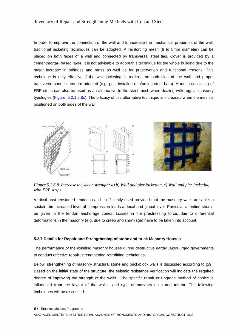
Inventory of Repair and Strengthening Methods with Iron and Steel
Erasmus Mundus Programme
ADVANCED MASTERS IN STRUCTURAL ANALYSIS OF MONUMENTS AND HISTORICAL CONSTRUCTIONS
97
In order to improve the connection of the wall and to increase the mechanical properties of the wall,
traditional jacketing techniques can be adopted. A reinforcing mesh (6 to 8mm diameter) can be
placed on both faces of a wall and connected by transversal steel ties. Cover is provided by a
cementmortar- based layer. It is not advisable to adopt this technique for the whole building due to the
major increase in stiffness and mass as well as for preservation and functional reasons. This
technique is only effective if the wall jacketing is realized on both side of the wall and proper
transverse connections are adopted (e.g. post-installed reinforcing steel bars). A mesh consisting of
FRP strips can also be used as an alternative to the steel mesh when dealing with regular masonry
typologies (Figure. 5.2.1.6.8c). The efficacy of this alternative technique is increased when the mesh is
positioned on both sides of the wall.
Figure 5.2.6.8. Increase the shear strength: a) b) Wall and pier jacketing, c) Wall and pier jacketing
with FRP strips. Vertical post tensioned tendons can be efficiently used provided that the masonry walls are able to
sustain the increased level of compression loads at local and global level. Particular attention should
be given to the tendon anchorage zones. Losses in the prestressing force, due to differential
deformations in the masonry (e.g. due to creep and shrinkage) have to be taken into account.
5.2.7 Details for Repair and Strengthening of stone and brick Masonry Houses
The performance of the exisiting masonry houses during destructive earthquakes urged governments
to conduct effective repair ,strengthening-retrofitting techniques.
Below, strengthening of masonry structural stone and brick/block walls is discussed according to [59].
Based on the initial state of the structure, the seismic resistance verification will indicate the required
degree of improving the strength of the walls . The specific repair or upgrade method of choice is
influenced from the layout of the walls and type of masonry units and mortar. The following
techniques will be discussed:
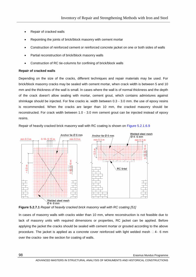
Inventory of Repair and Strengthening Methods with Iron and Steel
Erasmus Mundus Programme
ADVANCED MASTERS IN STRUCTURAL ANALYSIS OF MONUMENTS AND HISTORICAL CONSTRUCTIONS
98
Repair of cracked walls
Repointing the joints of brick/block masonry with cement mortar
Construction of reinforced cement or reinforced concrete jacket on one or both sides of walls
Partial reconstruction of brick/block masonry walls
Construction of RC tie-columns for confining of brick/block walls
Repair of cracked walls
Depending on the size of the cracks, different techniques and repair materials may be used. For
brick/block masonry cracks may be sealed with cement mortar, when crack width is between 5 and 10
mm and the thickness of the wall is small. In cases where the wall is of normal thickness and the depth
of the crack doesn't allow sealing with mortar, cement grout, which contains admixtures against
shrinkage should be injected. For fine cracks ie. width between 0.3 - 3.0 mm. the use of epoxy resins
is recommended. When the cracks are larger than 10 mm, the cracked masonry should be
reconstructed. For crack width between 1.0 - 3.0 mm cement grout can be injected instead of epoxy
resins.
Repair of heavily cracked brick masonry wall with RC coating is shown on Figure 5.2.1.6.9
Figure 5.2.7.1 Repair of heavily cracked brick masonry wall with RC coating [51] In cases of masonry walls with cracks wider than 10 mm, where reconstruction is not feasible due to
lack of masonry units with required dimensions or properties, RC jacket can be applied. Before
applying the jacket the cracks should be sealed with cement mortar or grouted according to the above
procedure. The jacket is applied as a concrete cover reinforced with light welded mesh 4 - 6 mm
over the cracks- see the section for coating of walls.

Inventory of Repair and Strengthening Methods with Iron and Steel
Erasmus Mundus Programme
ADVANCED MASTERS IN STRUCTURAL ANALYSIS OF MONUMENTS AND HISTORICAL CONSTRUCTIONS
99
Repointing the joints of brick/block masonry with cement mortar In cases of brick or block masonry
walls where the masonry was left unplastered the mortar can considerably deteriorate with time
especially if exposed to severe weather conditions. In addition to that if the brick or block masonry
walls built with poor quality mortar where the bed-joints are relatively leveled by replacing part of the
original mortar the mechanical properties of the walls can be improved. This technique is termed
repointing and should be carried out at only one face of the wall at a time.
The existing mortar can be removed using high-pressure water jet with pressure about 40 bar. The
depth of mortar removal can be max 1/3 of the wall thickness, due to the eccentricity of the
compression forces in the wall, and should be verified by calculation. After mortar removal the surface
should be prepared by cleaning watering. In cases where high-pressure water jet was used surface
preparation for repair is not necessary. When the joints in the brickwork are about 10 mm it is possible
to embed rebars in the joints to improve the dutility and strength of the masonry. The rebars should be
anchored at the ends of the wall panels by bending around the corner joints or in the case of confined
masonry in the tie-columns. The new cement mortar is then installed. After curing of the mortar on the
repaired side the procedure is repeated on the other face of the wall. A detail for wall repointing is
shown on Figure 5.2.7.2 below.
Figure 5.2.7.2 Repair and strengthening of brick masonry by repointing Construction of reinforced cement or reinforced concrete jacket on one or both sides of walls
This method is mostly used in the instances where strengthening of the wall is necessary for
rehabilitation purposes or when the wall was severely cracked and damaged in the event of an
earthquake. This method is applicable to most types of masonry walls and consists of applying
reinforced cement or concrete coatings onto one or both faces of a wall. However application of
coating on both sides is strongly recommended. The reinforcing material can be steel rebars mesh,
ferro-cement as well as carbon fibres or other carbon composites. The steps for reinforced cement
coating, applied to brickwork or blockwork, as described in [2] are :
In cases where the masonry is plastered, plaster should be removed

Inventory of Repair and Strengthening Methods with Iron and Steel
Erasmus Mundus Programme
ADVANCED MASTERS IN STRUCTURAL ANALYSIS OF MONUMENTS AND HISTORICAL CONSTRUCTIONS
100
Mortar is removed from the bed joints to a depth of 15 mm. The cracks in the wall are grouted
acoording to the procedure outlined above
The wall surface is cleaned, moistened with water and spattered with cement milk
Then the first layer is applied in the form of cement mortar with thickness 10 - 15 mm. The
stength of the cement mix should be around 20 MPa
The reinforcing mesh 4 - 6 mm at 100 - 150 mm intervals is placed
Holes are drilled through the wall for cross ties, 4 - 6 steel bars per m2
The steel bars( anchors) 6 mm are threaded through the holes and then grouted with
cement or epoxied
The reinforcing mesh is connected to the anchors. Minimum laps of the reinforcing mesh to be
300 mm
The second layer of cement is applied with thickness 10 - 15 mm
Detail showing application of RC coating to brick masonry wall is shown on Figure 5.2.1.6.1
. Figure 5.2.7.3-a Applying RC Coating to brick masonry wall [51]
For reinforcing the cement coating apart from steel bars, can be used ferro-cement, and carbon fibre
or polyester fibre composites. According to experimental studies lateral resistance of brick walls can
be approved with composites reinforcement to the same extent as with steel reinforcement.
Performance of jacketed brick and block masonry walls has been tested both in laboratory and in-situ.
The importance in the detail was found to be the cross-anchoring of the jackets through the wall. Table
5.2.7.1 displays test results for both brick and block masonry and different types of coating
reinforcement. Due to the substantial increase of the shear strength the bending strength of the walls
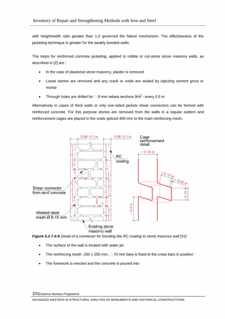
Inventory of Repair and Strengthening Methods with Iron and Steel
Erasmus Mundus Programme
ADVANCED MASTERS IN STRUCTURAL ANALYSIS OF MONUMENTS AND HISTORICAL CONSTRUCTIONS
101
with height/width ratio greater than 1.0 governed the failure mechanism. The effectiveness of the
jacketing technique is greater for the weakly bonded walls.
The steps for reinforced concrete jacketing, applied to rubble or cut-stone stone masonry walls, as
described in [2] are :
In the case of plastered stone masonry, plaster is removed
Loose stones are removed and any crack or voids are sealed by injecting cement grout or
mortar
Through holes are drilled for 8 mm rebars anchors 9/m2 - every 0.5 m
Alternatively in cases of thick walls or only one-sided jackets shear connectors can be formed with
reinforced concrete. For this purpose stones are removed from the walls in a regular pattern and
reinforcement cages are placed in the voids spliced 400 mm to the main reinforcing mesh.
Figure 5.2.7.4-b Detail of a connector for bonding the RC coating to stone masonry wall [51]
The surface of the wall is treated with water jet
The reinforcing mesh- 250 x 250 mm, 10 mm bars is fixed to the cross bars in position
The formwork is erected and the concrete is poured into
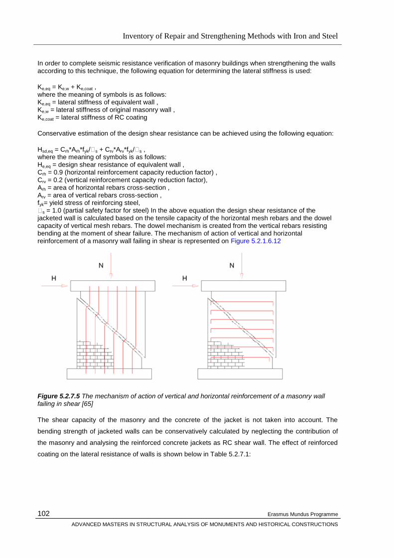
Inventory of Repair and Strengthening Methods with Iron and Steel
Erasmus Mundus Programme
ADVANCED MASTERS IN STRUCTURAL ANALYSIS OF MONUMENTS AND HISTORICAL CONSTRUCTIONS
102
In order to complete seismic resistance verification of masonry buildings when strengthening the walls according to this technique, the following equation for determining the lateral stiffness is used:
Ke,eq = Ke,w + Ke,coat , where the meaning of symbols is as follows: Ke,eq = lateral stiffness of equivalent wall , Ke,w = lateral stiffness of original masonry wall , Ke,coat = lateral stiffness of RC coating
Conservative estimation of the design shear resistance can be achieved using the following equation:
Hsd,eq = Crh*Arh*fyk/s + Crv*Arv*fyk/s , where the meaning of symbols is as follows: He,eq = design shear resistance of equivalent wall , Crh = 0.9 (horizontal reinforcement capacity reduction factor) , Crv = 0.2 (vertical reinforcement capacity reduction factor), Arh = area of horizontal rebars cross-section , Arv = area of vertical rebars cross-section , fyk= yield stress of reinforcing steel, s = 1.0 (partial safety factor for steel) In the above equation the design shear resistance of the jacketed wall is calculated based on the tensile capacity of the horizontal mesh rebars and the dowel capacity of vertical mesh rebars. The dowel mechanism is created from the vertical rebars resisting bending at the moment of shear failure. The mechanism of action of vertical and horizontal reinforcement of a masonry wall failing in shear is represented on Figure 5.2.1.6.12
Figure 5.2.7.5 The mechanism of action of vertical and horizontal reinforcement of a masonry wall failing in shear [65]
The shear capacity of the masonry and the concrete of the jacket is not taken into account. The
bending strength of jacketed walls can be conservatively calculated by neglecting the contribution of
the masonry and analysing the reinforced concrete jackets as RC shear wall. The effect of reinforced
coating on the lateral resistance of walls is shown below in Table 5.2.7.1:

Inventory of Repair and Strengthening Methods with Iron and Steel
Erasmus Mundus Programme
ADVANCED MASTERS IN STRUCTURAL ANALYSIS OF MONUMENTS AND HISTORICAL CONSTRUCTIONS
103
Partial reconstruction of brick/block masonry walls For brick and block masonry walls where crack
width is more than 10 mm the damaged masonry should be reconstructed as outlined in [59] The
damaged part of the wall should be demolished and reconstructed. The new masonry should be from
masonry units units the same type and dimensions as the existing ones. Cement mortar should be
used for the reconstruction. Steel masonry connectors can be embedded in mortar to improve the
connection between new and existing masonry as well as the bonding between the wall leaves. When
reconstructing masonry walls around openings, possible measure is to increase the strength and
stiffness of those zones. This can be achieved through construction of reinforced masonry or
reinforced concrete window frames. The downside is however the subsequent unpredictable
behaviour. Construction of RC tie-columns for confining of brick/block walls In the case of seismic
rehabilitation and retrofit of unreinforced brick/block masonry the building's integrity can be improved
by improving its structural system. In the past years, both in rural and urban areas of the world, a large
number of unreinforced masonry buildings with RC slabs have been constructed. In the cases where
RC bond-beams are provided under the floor slab the masonry of such houses can be effectively
confined by casting tie-columns at corners, wall intersections and on both sides of large openings.
Construction of new tie-column at T junction in brick masonry wall is shown on Figure 5.2.7.6
Type of masonry Type of cement
reinforcement
Lateral resistance
Multiplier Masonry unit
Grade
Mortar Grade
Original [kN]
Strengthened [kN]
Brick, B20 M 0.4 Steel 34 118 3.5
Brick, B10 M 0.3 Steel 47 167 3.6
C. block, B7.5
M 5 Steel 128 167 1.3
Brick, B20 M 7.2 Ferro-cement 276 693 2.5
Brick, B15 - Carbon 299 426 1.4
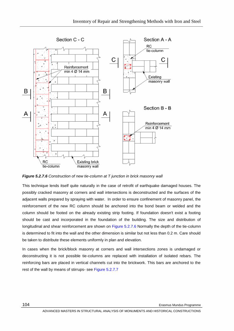
Inventory of Repair and Strengthening Methods with Iron and Steel
Erasmus Mundus Programme
ADVANCED MASTERS IN STRUCTURAL ANALYSIS OF MONUMENTS AND HISTORICAL CONSTRUCTIONS
104
Figure 5.2.7.6 Construction of new tie-column at T junction in brick masonry wall
This technique lends itself quite naturally in the case of retrofit of earthquake damaged houses. The
possibly cracked masonry at corners and wall intersections is deconstructed and the surfaces of the
adjacent walls prepared by spraying with water. In order to ensure confinement of masonry panel, the
reinforcement of the new RC column should be anchored into the bond beam or welded and the
column should be footed on the already existing strip footing. If foundation doesn't exist a footing
should be cast and incorporated in the foundation of the building. The size and distribution of
longitudinal and shear reinforcement are shown on Figure 5.2.7.6 Normally the depth of the tie-column
is determined to fit into the wall and the other dimension is similar but not less than 0.2 m. Care should
be taken to distribute these elements uniformly in plan and elevation.
In cases when the brick/block masonry at corners and wall intersections zones is undamaged or
deconstructing it is not possible tie-columns are replaced with installation of isolated rebars. The
reinforcing bars are placed in vertical channels cut into the brickwork. This bars are anchored to the
rest of the wall by means of stirrups- see Figure 5.2.7.7
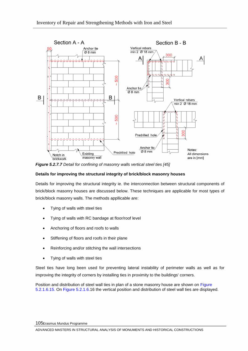
Inventory of Repair and Strengthening Methods with Iron and Steel
Erasmus Mundus Programme
ADVANCED MASTERS IN STRUCTURAL ANALYSIS OF MONUMENTS AND HISTORICAL CONSTRUCTIONS
105
Figure 5.2.7.7 Detail for confining of masonry walls vertical steel ties [45] Details for improving the structural integrity of brick/block masonry houses
Details for improving the structural integrity ie. the interconnection between structural components of
brick/block masonry houses are discussed below. These techniques are applicable for most types of
brick/block masonry walls. The methods appllicable are:
Tying of walls with steel ties
Tying of walls with RC bandage at floor/roof level
Anchoring of floors and roofs to walls
Stiffening of floors and roofs in their plane
Reinforcing and/or stitching the wall intersections
Tying of walls with steel ties
Steel ties have long been used for preventing lateral instability of perimeter walls as well as for
improving the integrity of corners by installing ties in proximity to the buildings' corners.
Position and distribution of steel wall ties in plan of a stone masonry house are shown on Figure 5.2.1.6.15. On Figure 5.2.1.6.16 the vertical position and distribution of steel wall ties are displayed.

Inventory of Repair and Strengthening Methods with Iron and Steel
Erasmus Mundus Programme
ADVANCED MASTERS IN STRUCTURAL ANALYSIS OF MONUMENTS AND HISTORICAL CONSTRUCTIONS
106
Figure 5.2.7.8 Position and distribution of steel ties in plan of a stone masonry house
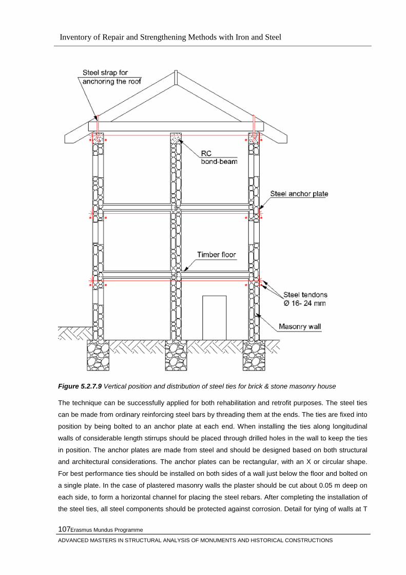
Inventory of Repair and Strengthening Methods with Iron and Steel
Erasmus Mundus Programme
ADVANCED MASTERS IN STRUCTURAL ANALYSIS OF MONUMENTS AND HISTORICAL CONSTRUCTIONS
107
Figure 5.2.7.9 Vertical position and distribution of steel ties for brick & stone masonry house The technique can be successfully applied for both rehabilitation and retrofit purposes. The steel ties
can be made from ordinary reinforcing steel bars by threading them at the ends. The ties are fixed into
position by being bolted to an anchor plate at each end. When installing the ties along longitudinal
walls of considerable length stirrups should be placed through drilled holes in the wall to keep the ties
in position. The anchor plates are made from steel and should be designed based on both structural
and architectural considerations. The anchor plates can be rectangular, with an X or circular shape.
For best performance ties should be installed on both sides of a wall just below the floor and bolted on
a single plate. In the case of plastered masonry walls the plaster should be cut about 0.05 m deep on
each side, to form a horizontal channel for placing the steel rebars. After completing the installation of
the steel ties, all steel components should be protected against corrosion. Detail for tying of walls at T

Inventory of Repair and Strengthening Methods with Iron and Steel
Erasmus Mundus Programme
ADVANCED MASTERS IN STRUCTURAL ANALYSIS OF MONUMENTS AND HISTORICAL CONSTRUCTIONS
108
junction using steel ties is shown on Figure 5.2.7.10 On Figure 5.2.1.7.11, detail of anchoring of wall
steel ties at a corner is displayed.
Figure 5.2.7.10 Detail for tying of walls at T junction using steel ties [46]

Inventory of Repair and Strengthening Methods with Iron and Steel
Erasmus Mundus Programme
ADVANCED MASTERS IN STRUCTURAL ANALYSIS OF MONUMENTS AND HISTORICAL CONSTRUCTIONS
109
Figure 5.2.7.11 Detail of anchoring of wall steel ties at a corner [46]
According to [61], the performance of ties is governed by:
In case when steel ties are placed along the walls being transverse in respect to the seismic
motion, the ties together with the upper part of wall perform like a bond-beam. Consequently
ties together with a strip of the upper part of wall should be designed to sustain a bending
moment, due to the out-of-plane wall vibration. According to this criteria both ties should be
identical and designed just like longitudinal bond-beam reinforcement.
In case when steel ties are placed along the walls being longitudinal in respect to the seismic
motion, the ties take part in the global structural response by forming horizontal tensile( no
compression) members at each floor level. A global truss system develops, where the
compression forces carried from compression masonry diagonals are carried over from
strorey to storey, thanks to the horizontal truss members ie. the steel ties. From the
Inventory of Repair and Strengthening Methods with Iron and Steel
Erasmus Mundus Programme
ADVANCED MASTERS IN STRUCTURAL ANALYSIS OF MONUMENTS AND HISTORICAL CONSTRUCTIONS
110
experimental studies [ 61] , forces which develop in the longitudinal ties at ultimate state are
close to the seismic shear force induced in the models.
Consequently at least two design checks are required for each tie to estimate its min diameter. The biggest determined wall tie diameter from the design checks for all ties, in plan and elevation, should be used throughout the building. The minimum diameter of a single tie rebar can be determined by the formulae:
Dmin = SQRT(4*Hu,seg/*n*fy) ,
where the meaning of symbols is as follows:
Dmin = the minimum tie diameter ,
Hu,seg = the ultimate seismic resistance of critical portion of the building ,
fy = the yield stress of reinforcing steel ,
n = the number of ties (rebars) ,
Tying of walls with RC bandage at floor level
Broad horizontal bandages at lintel or roof level are also recommended .The steel mesh should be
fixed to the brick/block wall by means of flat steel ties at 400mm horizontal and 400mm vertical
intervals. The steel ties should be embedded in the masonry wall through purposely drilled holes. After
completion of the wall a base of cement:sand mortar, mixed in 1:3 proportion and thickness 15mm, for
the steel mesh should be installed. The welded steel mesh, minimum 5 @ 50x50 pitches, should be
attached to the already cast strip of mortar by means of the embedded ties. Finally a second mortar
layer of 15mm thickness is installed to complete the reinforcing bandages.
The steel ties should be embedded in the adobe masonry during construction. After completion of the
wall a base of cement:sand mortar, mixed in 1:4 proportion and thickness 15mm, for the steel mesh
should be installed. The welded steel mesh (diameter min 2mm @ 50x50 pitches) should be attached
to the already cast strip of mortar by means of the embedded ties. Finally a second mortar layer 15mm

Inventory of Repair and Strengthening Methods with Iron and Steel
Erasmus Mundus Programme
ADVANCED MASTERS IN STRUCTURAL ANALYSIS OF MONUMENTS AND HISTORICAL CONSTRUCTIONS
111
thickness is installed to complete the reinforcing bandages. See Figure 13 and Figure 14 for
Figure 5.2.7.12 Tying of walls with steel reinfrocement
Figure 5.2.7.13 Tying of walls with steel mesh- detail

Inventory of Repair and Strengthening Methods with Iron and Steel
Erasmus Mundus Programme
ADVANCED MASTERS IN STRUCTURAL ANALYSIS OF MONUMENTS AND HISTORICAL CONSTRUCTIONS
112
Anchoring of floors and roofs to walls
The techniques for anchoring of floors and roofs to brick/block walls are applicable to both brick and
stone masonry buildings.
In the case of masonry buildings with timber floors tying the walls together at wall intersections, with
steel ties, it is not enough to ensure monolithic performance ,especially in the case where distance
between transverse-cross walls is significant. To reduce uncoupled wall vibrations and prevent
possible out-of-plane cracking or failure, the walls need to be anchored along their span with steel
connectors to the floor joists.
Figure 5.2.7.14 Position and distribution of wall and floor joists steel ties in plan of a stone masonry house
L >= 0.5m
l1 >= 50mm
l2 >= T+l4
l3 = 50mm
l4 = 15mm
T >= 0.25m
D >= T+0.6m
H = 0.4m
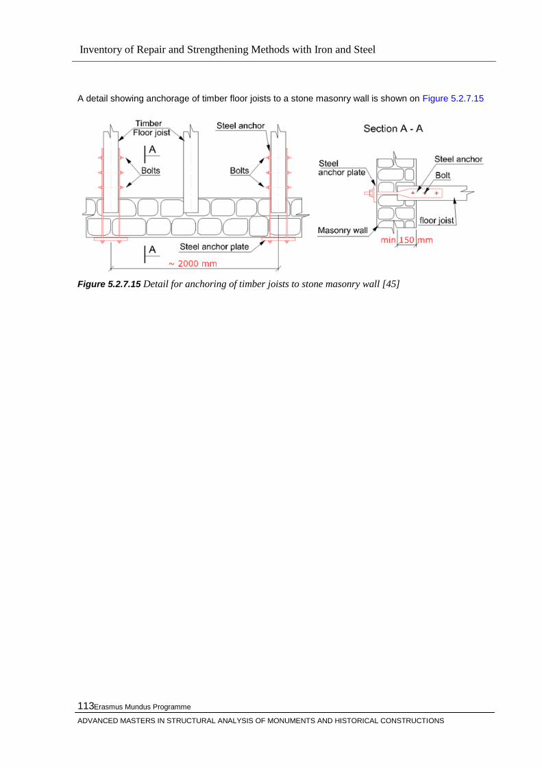
Inventory of Repair and Strengthening Methods with Iron and Steel
Erasmus Mundus Programme
ADVANCED MASTERS IN STRUCTURAL ANALYSIS OF MONUMENTS AND HISTORICAL CONSTRUCTIONS
113
A detail showing anchorage of timber floor joists to a stone masonry wall is shown on Figure 5.2.7.15
Figure 5.2.7.15 Detail for anchoring of timber joists to stone masonry wall [45]

Inventory of Repair and Strengthening Methods with Iron and Steel
Erasmus Mundus Programme
ADVANCED MASTERS IN STRUCTURAL ANALYSIS OF MONUMENTS AND HISTORICAL CONSTRUCTIONS
114
Figure 5.2.7.16 Detail for anchoring of floor joists to masonry walls [46]

Inventory of Repair and Strengthening Methods with Iron and Steel
Erasmus Mundus Programme
ADVANCED MASTERS IN STRUCTURAL ANALYSIS OF MONUMENTS AND HISTORICAL CONSTRUCTIONS
115
Furthermore in cases where the floor structure is weakly connected to walls this technique will prevent
sliding mechanism and collapse of the floor. Depending on the structure of the timber floor and the
distance between cross walls is determined the position of the steel connectors. Apart from connecting
the floor joists to walls by means of steel connectors, additional diagonal ties can be installed. In the
case of considerable distance between cross walls, and complications with anchoring of existing
timber components to walls, a complete metal truss can be installed on top of the timber structure
below the floor finish. The steel truss is placed so that its sides are in contact with at least three
adjacent walls. Using steel anchor bolts the truss is connected to the walls - Figure 5.2.7.17
Figure 5.2.7.17 Sstiffening of a large span timber floor by placement of steel truss [45] Stiffening of floors and roofs in their plane
In order to achieve distribution of seismic forces in respect to the walls stiffness the floors and/or roofs
must be ideally stiff in their plane. In this case is said that the floors are acting like horizontal
diaphragm. Semi-flexible or flexible floors/roofs distribute the seismic loads based on the floor to wall
stiffness ratio or based on tributary wall areas. For retrofit purposes, especially when the timber floor
and/or roof structure is damaged a straightforward solution is to replace it with cast in-situ reinforced
concrete slab. Simultaneously with the slab are casted perimeter bond-beams on top of all walls.
Installation of new RC slab is shown on Figure 5.2.1.6.25. If the perimeter bond-beams do not pass
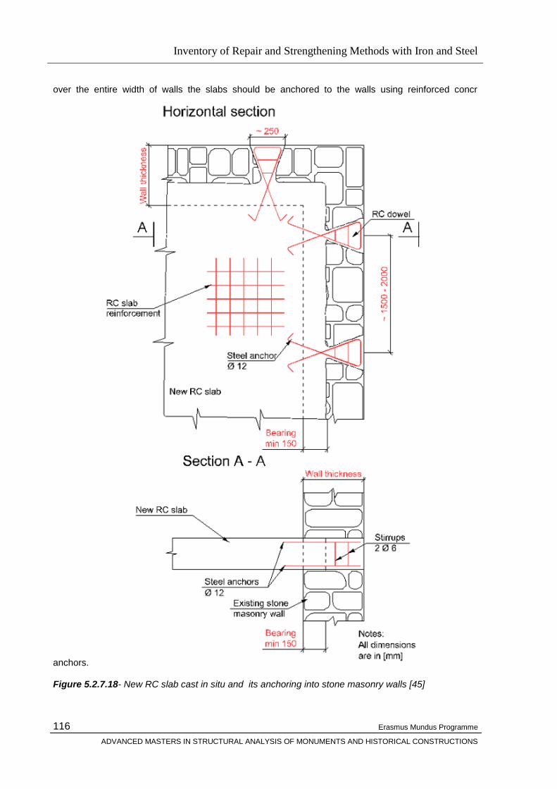
Inventory of Repair and Strengthening Methods with Iron and Steel
Erasmus Mundus Programme
ADVANCED MASTERS IN STRUCTURAL ANALYSIS OF MONUMENTS AND HISTORICAL CONSTRUCTIONS
116
over the entire width of walls the slabs should be anchored to the walls using reinforced concr
anchors.
Figure 5.2.7.18- New RC slab cast in situ and its anchoring into stone masonry walls [45]
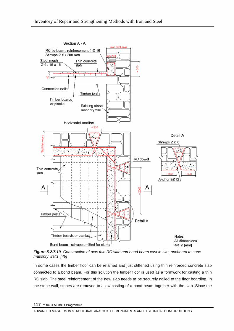
Inventory of Repair and Strengthening Methods with Iron and Steel
Erasmus Mundus Programme
ADVANCED MASTERS IN STRUCTURAL ANALYSIS OF MONUMENTS AND HISTORICAL CONSTRUCTIONS
117
Figure 5.2.7.19- Construction of new thin RC slab and bond beam cast in situ, anchored to sone masonry walls [46] In some cases the timber floor can be retained and just stiffened using thin reinforced concrete slab
connected to a bond beam. For this solution the timber floor is used as a formwork for casting a thin
RC slab. The steel reinforcement of the new slab needs to be securely nailed to the floor boarding. In
the stone wall, stones are removed to allow casting of a bond beam together with the slab. Since the

Inventory of Repair and Strengthening Methods with Iron and Steel
Erasmus Mundus Programme
ADVANCED MASTERS IN STRUCTURAL ANALYSIS OF MONUMENTS AND HISTORICAL CONSTRUCTIONS
118
bond beam would only partially engage the walls, a through RC dowels are needed to anchor the
bond beam to the walls - see Figure 5.2.7.19, below.
For rehabilitation purposes, when the quality of the timber floors and/or roofs is good, stiffening of the
floors can be achieved by nailing timber planks perpendicular to the floor joists. Depending on access
this can be done both on top and bottom faces of joists. In the case of nailing on only one face two
layers of sheathing is applied, see Figure 14. Plywood sheets can also be used.
Figure 5.2.7.20-a Stiffening of timber floors by nailing boards or planks
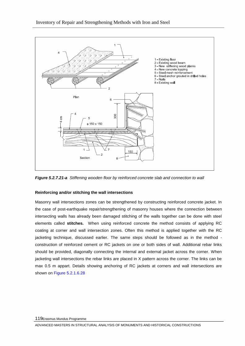
Inventory of Repair and Strengthening Methods with Iron and Steel
Erasmus Mundus Programme
ADVANCED MASTERS IN STRUCTURAL ANALYSIS OF MONUMENTS AND HISTORICAL CONSTRUCTIONS
119
Figure 5.2.7.21-a Stiffening wooden floor by reinforced concrete slab and connection to wall
Reinforcing and/or stitching the wall intersections
Masonry wall intersections zones can be strengthened by constructing reinforced concrete jacket. In
the case of post-earthquake repair/strengthening of masonry houses where the connection between
intersecting walls has already been damaged stitching of the walls together can be done with steel
elements called stitches. When using reinforced concrete the method consists of applying RC
coating at corner and wall intersection zones. Often this method is applied together with the RC
jacketing technique, discussed earlier. The same steps should be followed as in the method -
construction of reinforced cement or RC jackets on one or both sides of wall. Additional rebar links
should be provided, diagonally connecting the internal and external jacket across the corner. When
jacketing wall intersections the rebar links are placed in X pattern across the corner. The links can be
max 0.5 m appart. Details showing anchoring of RC jackets at corners and wall intersections are
shown on Figure 5.2.1.6.28
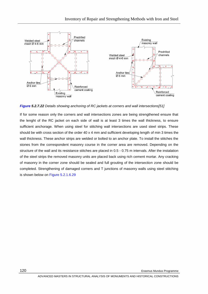
Inventory of Repair and Strengthening Methods with Iron and Steel
Erasmus Mundus Programme
ADVANCED MASTERS IN STRUCTURAL ANALYSIS OF MONUMENTS AND HISTORICAL CONSTRUCTIONS
120
Figure 5.2.7.22 Details showing anchoring of RC jackets at corners and wall intersections[51]
If for some reason only the corners and wall intersections zones are being strengthened ensure that
the lenght of the RC jacket on each side of wall is at least 3 times the wall thickness, to ensure
sufficient anchorage. When using steel for stitching wall intersections are used steel strips. These
should be with cross section of the order 40 x 4 mm and sufficient developing length of min 3 times the
wall thickness. These anchor strips are welded or bolted to an anchor plate. To install the stitches the
stones from the correspondent masonry course in the corner area are removed. Depending on the
structure of the wall and its resistance stitches are placed in 0.5 - 0.75 m intervals. After the instalation
of the steel strips the removed masonry units are placed back using rich cement mortar. Any cracking
of masonry in the corner zone should be sealed and full grouting of the intersection zone should be
completed. Strengthening of damaged corners and T junctions of masonry walls using steel stitching
is shown below on Figure 5.2.1.6.29

Inventory of Repair and Strengthening Methods with Iron and Steel
Erasmus Mundus Programme
ADVANCED MASTERS IN STRUCTURAL ANALYSIS OF MONUMENTS AND HISTORICAL CONSTRUCTIONS
121
Figure 5.2.7.23 Strengthening of corners and T junctions of masonry walls using steel[51] stitching
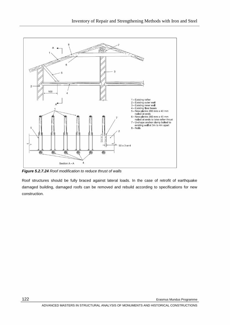
Inventory of Repair and Strengthening Methods with Iron and Steel
Erasmus Mundus Programme
ADVANCED MASTERS IN STRUCTURAL ANALYSIS OF MONUMENTS AND HISTORICAL CONSTRUCTIONS
122
Figure 5.2.7.24 Roof modification to reduce thrust of walls
Roof structures should be fully braced against lateral loads. In the case of retrofit of earthquake
damaged building, damaged roofs can be removed and rebuild according to specifications for new
construction.
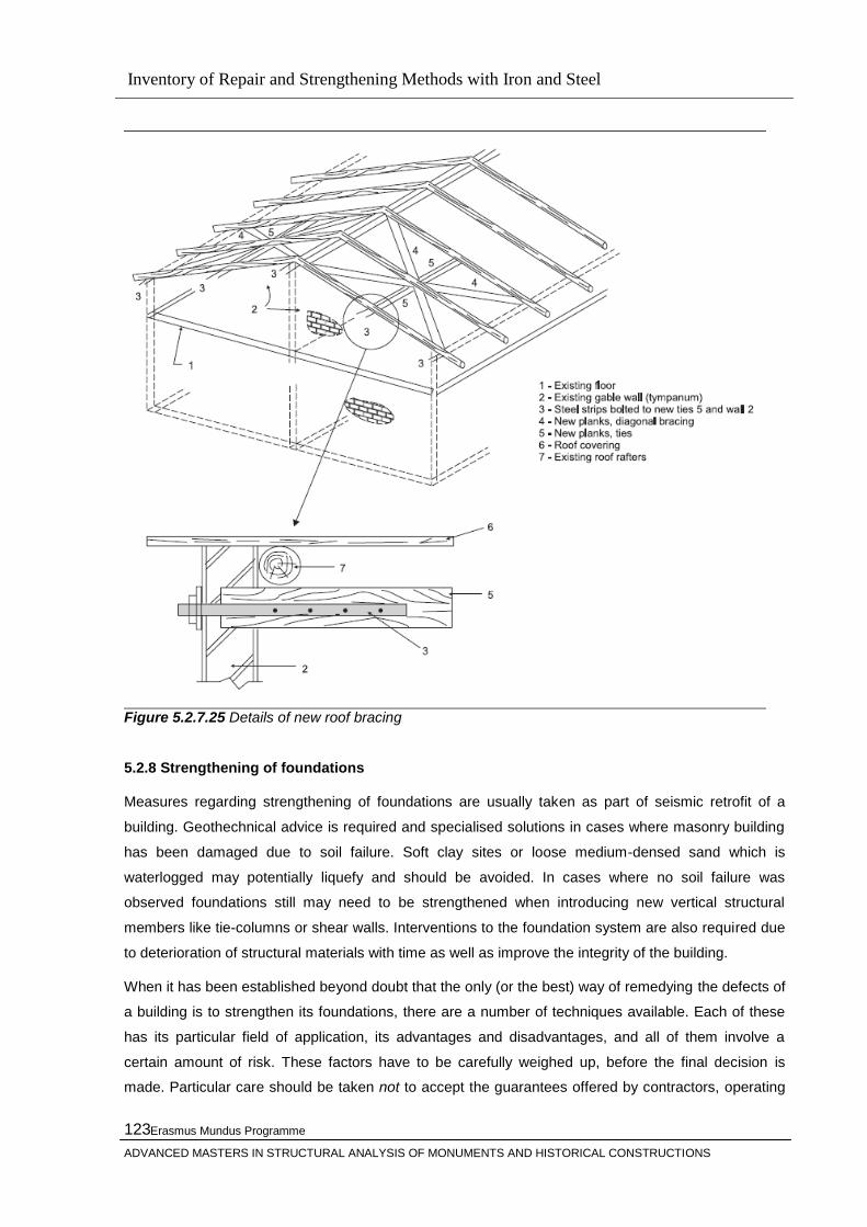
Inventory of Repair and Strengthening Methods with Iron and Steel
Erasmus Mundus Programme
ADVANCED MASTERS IN STRUCTURAL ANALYSIS OF MONUMENTS AND HISTORICAL CONSTRUCTIONS
123
Figure 5.2.7.25 Details of new roof bracing
5.2.8 Strengthening of foundations
Measures regarding strengthening of foundations are usually taken as part of seismic retrofit of a
building. Geothechnical advice is required and specialised solutions in cases where masonry building
has been damaged due to soil failure. Soft clay sites or loose medium-densed sand which is
waterlogged may potentially liquefy and should be avoided. In cases where no soil failure was
observed foundations still may need to be strengthened when introducing new vertical structural
members like tie-columns or shear walls. Interventions to the foundation system are also required due
to deterioration of structural materials with time as well as improve the integrity of the building.
When it has been established beyond doubt that the only (or the best) way of remedying the defects of
a building is to strengthen its foundations, there are a number of techniques available. Each of these
has its particular field of application, its advantages and disadvantages, and all of them involve a
certain amount of risk. These factors have to be carefully weighed up, before the final decision is
made. Particular care should be taken not to accept the guarantees offered by contractors, operating

Inventory of Repair and Strengthening Methods with Iron and Steel
Erasmus Mundus Programme
ADVANCED MASTERS IN STRUCTURAL ANALYSIS OF MONUMENTS AND HISTORICAL CONSTRUCTIONS
124
proprietary techniques, without reading ‗the small print‘ which may invalidate the guarantee, if certain
unforeseen conditions are encountered during the work. The advice of an engineer with specialist
geotechnical knowledge and with experience in foundation strengthening, as well as familiarity with
the structural characteristics of old structures, should always be sought, regardless of the method
envisaged.
Existing old masonry buildings are often without foundations. The vertical loads are transferred to the
soil directly through the basement walls. In such cases construction of RC strip foundations under the
basement walls can be applied. Depending on access limitations or ownership boundaries, the new
strip foundations can be constructed by stitching to the sides of the existing basement walls or
foundations. Before strengthening the existing foundations, the walls are first consolidated by grouting.
As discused in [62] hydrophobic additives may be added to cement grout in order to prevent the
propagation of humidity. Typically RC strip foundations are constructed under the walls for
strengthening of basement walls or foundations.
Figure 5.2.8.1 York Minster exploratory excavation
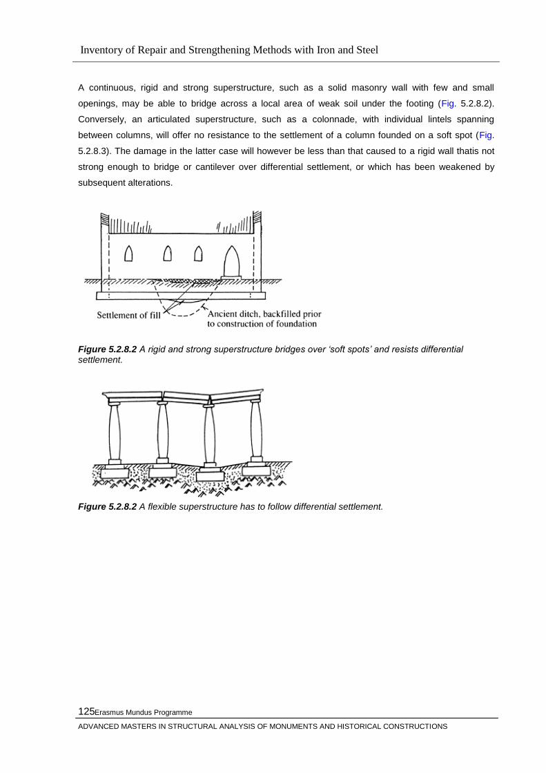
Inventory of Repair and Strengthening Methods with Iron and Steel
Erasmus Mundus Programme
ADVANCED MASTERS IN STRUCTURAL ANALYSIS OF MONUMENTS AND HISTORICAL CONSTRUCTIONS
125
A continuous, rigid and strong superstructure, such as a solid masonry wall with few and small
openings, may be able to bridge across a local area of weak soil under the footing (Fig. 5.2.8.2).
Conversely, an articulated superstructure, such as a colonnade, with individual lintels spanning
between columns, will offer no resistance to the settlement of a column founded on a soft spot (Fig.
5.2.8.3). The damage in the latter case will however be less than that caused to a rigid wall thatis not
strong enough to bridge or cantilever over differential settlement, or which has been weakened by
subsequent alterations.
Figure 5.2.8.2 A rigid and strong superstructure bridges over „soft spots‟ and resists differential settlement.
Figure 5.2.8.2 A flexible superstructure has to follow differential settlement.
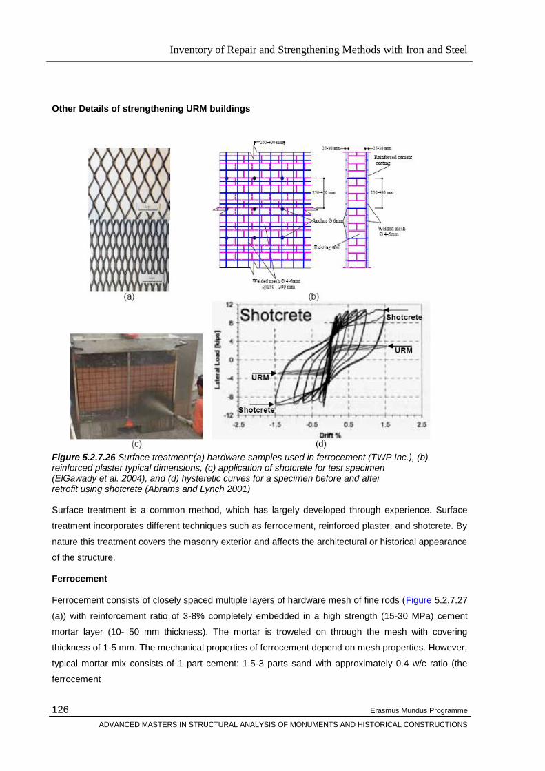
Inventory of Repair and Strengthening Methods with Iron and Steel
Erasmus Mundus Programme
ADVANCED MASTERS IN STRUCTURAL ANALYSIS OF MONUMENTS AND HISTORICAL CONSTRUCTIONS
126
Other Details of strengthening URM buildings
Figure 5.2.7.26 Surface treatment:(a) hardware samples used in ferrocement (TWP Inc.), (b) reinforced plaster typical dimensions, (c) application of shotcrete for test specimen (ElGawady et al. 2004), and (d) hysteretic curves for a specimen before and after retrofit using shotcrete (Abrams and Lynch 2001)
Surface treatment is a common method, which has largely developed through experience. Surface
treatment incorporates different techniques such as ferrocement, reinforced plaster, and shotcrete. By
nature this treatment covers the masonry exterior and affects the architectural or historical appearance
of the structure.
Ferrocement
Ferrocement consists of closely spaced multiple layers of hardware mesh of fine rods (Figure 5.2.7.27
(a)) with reinforcement ratio of 3-8% completely embedded in a high strength (15-30 MPa) cement
mortar layer (10- 50 mm thickness). The mortar is troweled on through the mesh with covering
thickness of 1-5 mm. The mechanical properties of ferrocement depend on mesh properties. However,
typical mortar mix consists of 1 part cement: 1.5-3 parts sand with approximately 0.4 w/c ratio (the
ferrocement
Inventory of Repair and Strengthening Methods with Iron and Steel
Erasmus Mundus Programme
ADVANCED MASTERS IN STRUCTURAL ANALYSIS OF MONUMENTS AND HISTORICAL CONSTRUCTIONS
127
network, Montes and Fernandez 2001). The behavior of the mortar can be improved by adding 0.5-1%
of a low-cost fiber such as polypropylene. Ferrocement is ideal for low cost housing since it is cheap
and can be done with unskilled workers. It improves both in-plane and out-of-plane behavior. The
mesh helps to confine the masonry units after cracking and thus improves in-plane inelastic
deformation capacity. In a static cyclic test (Abrams and Lynch 2001), this retrofitting technique
increased the in-plane lateral resistance by a factor of 1.5. Regarding out-ofplane behavior,
ferrocement improves wall out-of-plane stability and arching action since it increases the wall height-
to-thickness ratio.
Reinforced plaster
A thin layer of cement plaster applied over high strength steel reinforcement can be used for
retrofitting (Sheppard and Tercelj 1980). The steel can be arranged as diagonal bars or as a vertical
and horizontal mesh. A reinforced plaster can be applied as shown in Figure 1 (b). In diagonal tension
test and static cyclic tests, the technique was able to improve the in-plane resistance by a factor of
1.25-3 (Jabarov et al. 1980, Sheppard and Tercelj 1980). The improvement in strength depends on
the strengthening layer thickness, the cement mortar strength, the reinforcement quantity and the
means of its bonding with the retrofitted wall, and the degree of masonry damage.
Shotcrete
Shotcrete overlays are sprayed onto the surface of a masonry wall over a mesh of reinforcing bars
(Figure5.2.1.6.32 (c)). Shotcrete is more convenient and less costly than castin-situ jackets. The
thickness of the shotcrete can be adapted to the seismic demand. In general, the overlay thickness is
at least 60 mm (Abrams and Lynch 2001, Tomazevic 1999, Karantoni and Faradis 1992, Kahn 1984,
Hutchison et al. 1984). The shotcrete overlay is typically reinforced with a welded wire fabric at about
the minimum steel ratio for crack control (Karantoni and Fardis 1992). In order to transfer the shear
stress across shotcrete-masonry interface, shear dowels (6-13 mm diameter @ 25-120 mm) are fixed
using epoxy or cement grout into holes drilled into the masonry wall (Abrams and Lynch 2001,
Tomazevic 1999, Karantoni and Faradis 1992, Kahn 1984). Other engineers believe that a bonding
agent like epoxy is required to be painted or sprayed on the brick so that adequate brick-shotcrete
bond is developed (Kahn 1984). However, there is no consensus on brick-to-shotcrete bonding and
the need for dowels. Diagonal tension tests of single and double wythe URM panels (Kahn 1984)
retrofitted with shotcrete showed that, dowels did not improve the composite panels response or the
brick-shotcrete bonding; header bricks satisfactory joined the wythe of existing masonry panels. In
addition, Tomazevic (1999) and Kahn (1984) recommended wetting the masonry surface prior to
applying shotcrete. Kahn (1984) shows that such brick surface treatment does not affect significantly
the cracking or ultimate load, it affects to limited extend the inelastic deformations. Retrofitting using
shotcrete significantly increases the ultimate load of the retrofitted walls. Using a one-sided 90 mm
thick shotcrete overlay and in diagonal tension test, Kahn (1984) increased the ultimate load of URM
panels by a factor of 6-25. Abrams
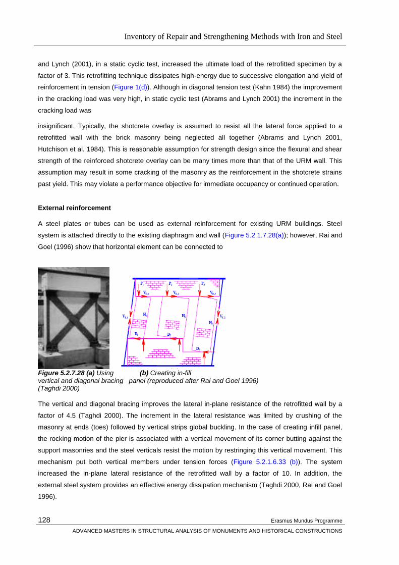
Inventory of Repair and Strengthening Methods with Iron and Steel
Erasmus Mundus Programme
ADVANCED MASTERS IN STRUCTURAL ANALYSIS OF MONUMENTS AND HISTORICAL CONSTRUCTIONS
128
and Lynch (2001), in a static cyclic test, increased the ultimate load of the retrofitted specimen by a
factor of 3. This retrofitting technique dissipates high-energy due to successive elongation and yield of
reinforcement in tension (Figure 1(d)). Although in diagonal tension test (Kahn 1984) the improvement
in the cracking load was very high, in static cyclic test (Abrams and Lynch 2001) the increment in the
cracking load was
insignificant. Typically, the shotcrete overlay is assumed to resist all the lateral force applied to a
retrofitted wall with the brick masonry being neglected all together (Abrams and Lynch 2001,
Hutchison et al. 1984). This is reasonable assumption for strength design since the flexural and shear
strength of the reinforced shotcrete overlay can be many times more than that of the URM wall. This
assumption may result in some cracking of the masonry as the reinforcement in the shotcrete strains
past yield. This may violate a performance objective for immediate occupancy or continued operation.
External reinforcement
A steel plates or tubes can be used as external reinforcement for existing URM buildings. Steel
system is attached directly to the existing diaphragm and wall (Figure 5.2.1.7.28(a)); however, Rai and
Goel (1996) show that horizontal element can be connected to
Figure 5.2.7.28 (a) Using (b) Creating in-fill vertical and diagonal bracing panel (reproduced after Rai and Goel 1996) (Taghdi 2000)
The vertical and diagonal bracing improves the lateral in-plane resistance of the retrofitted wall by a
factor of 4.5 (Taghdi 2000). The increment in the lateral resistance was limited by crushing of the
masonry at ends (toes) followed by vertical strips global buckling. In the case of creating infill panel,
the rocking motion of the pier is associated with a vertical movement of its corner butting against the
support masonries and the steel verticals resist the motion by restringing this vertical movement. This
mechanism put both vertical members under tension forces (Figure 5.2.1.6.33 (b)). The system
increased the in-plane lateral resistance of the retrofitted wall by a factor of 10. In addition, the
external steel system provides an effective energy dissipation mechanism (Taghdi 2000, Rai and Goel
1996).
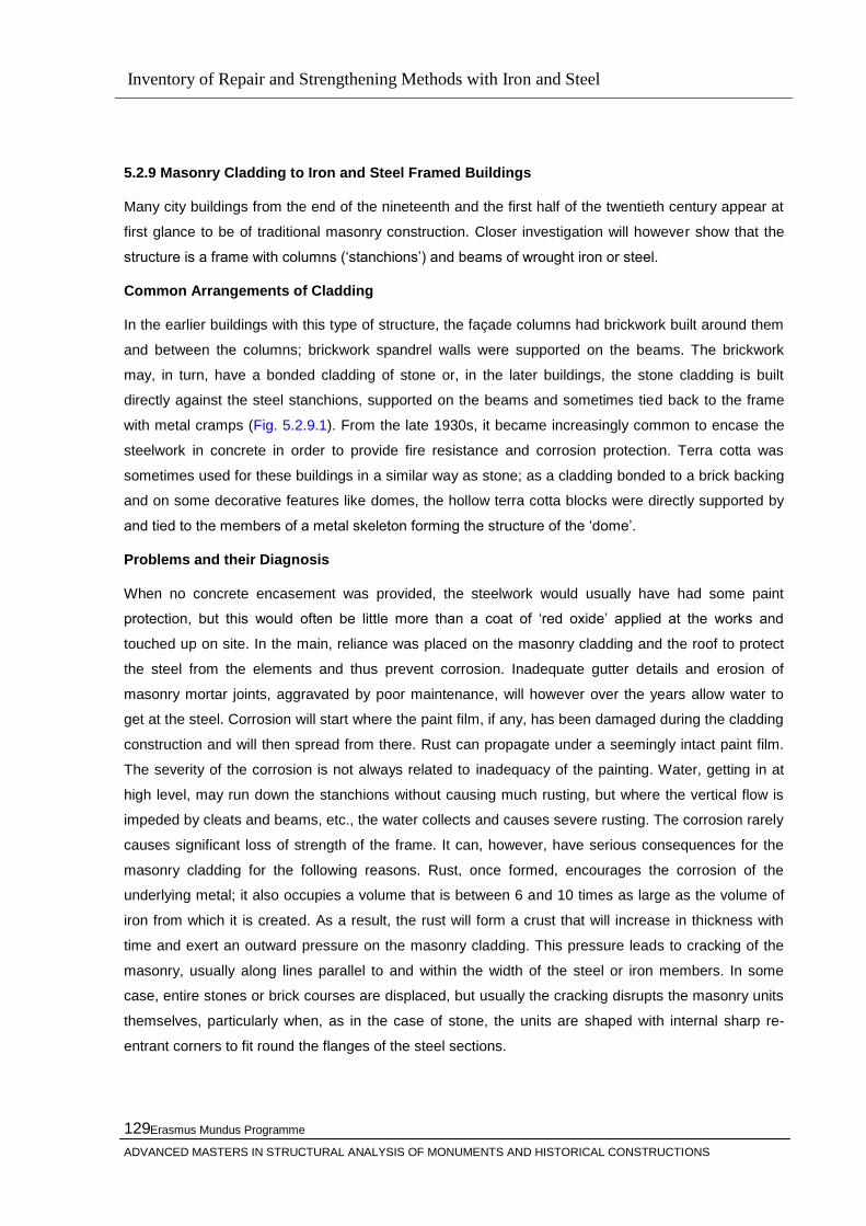
Inventory of Repair and Strengthening Methods with Iron and Steel
Erasmus Mundus Programme
ADVANCED MASTERS IN STRUCTURAL ANALYSIS OF MONUMENTS AND HISTORICAL CONSTRUCTIONS
129
5.2.9 Masonry Cladding to Iron and Steel Framed Buildings
Many city buildings from the end of the nineteenth and the first half of the twentieth century appear at
first glance to be of traditional masonry construction. Closer investigation will however show that the
structure is a frame with columns (‗stanchions‘) and beams of wrought iron or steel.
Common Arrangements of Cladding
In the earlier buildings with this type of structure, the façade columns had brickwork built around them
and between the columns; brickwork spandrel walls were supported on the beams. The brickwork
may, in turn, have a bonded cladding of stone or, in the later buildings, the stone cladding is built
directly against the steel stanchions, supported on the beams and sometimes tied back to the frame
with metal cramps (Fig. 5.2.9.1). From the late 1930s, it became increasingly common to encase the
steelwork in concrete in order to provide fire resistance and corrosion protection. Terra cotta was
sometimes used for these buildings in a similar way as stone; as a cladding bonded to a brick backing
and on some decorative features like domes, the hollow terra cotta blocks were directly supported by
and tied to the members of a metal skeleton forming the structure of the ‗dome‘.
Problems and their Diagnosis
When no concrete encasement was provided, the steelwork would usually have had some paint
protection, but this would often be little more than a coat of ‗red oxide‘ applied at the works and
touched up on site. In the main, reliance was placed on the masonry cladding and the roof to protect
the steel from the elements and thus prevent corrosion. Inadequate gutter details and erosion of
masonry mortar joints, aggravated by poor maintenance, will however over the years allow water to
get at the steel. Corrosion will start where the paint film, if any, has been damaged during the cladding
construction and will then spread from there. Rust can propagate under a seemingly intact paint film.
The severity of the corrosion is not always related to inadequacy of the painting. Water, getting in at
high level, may run down the stanchions without causing much rusting, but where the vertical flow is
impeded by cleats and beams, etc., the water collects and causes severe rusting. The corrosion rarely
causes significant loss of strength of the frame. It can, however, have serious consequences for the
masonry cladding for the following reasons. Rust, once formed, encourages the corrosion of the
underlying metal; it also occupies a volume that is between 6 and 10 times as large as the volume of
iron from which it is created. As a result, the rust will form a crust that will increase in thickness with
time and exert an outward pressure on the masonry cladding. This pressure leads to cracking of the
masonry, usually along lines parallel to and within the width of the steel or iron members. In some
case, entire stones or brick courses are displaced, but usually the cracking disrupts the masonry units
themselves, particularly when, as in the case of stone, the units are shaped with internal sharp re-
entrant corners to fit round the flanges of the steel sections.

Inventory of Repair and Strengthening Methods with Iron and Steel
Erasmus Mundus Programme
ADVANCED MASTERS IN STRUCTURAL ANALYSIS OF MONUMENTS AND HISTORICAL CONSTRUCTIONS
130
Figure 5.2.9.1 Details of masonry cladding to steel-framed building (from Warland, 1953)
The diagnosis is simple in principle; once it is established that the building has an iron or steel frame,
cracks on the façade along the lines of the metal frame members behind the face indicate serious
corrosion underneath. The extent of the trouble is, however, far more difficult to ascertain, as absence
of cracks does not prove absence of rust. The reason for this is that due to the inaccuracies in the
relative alignment of the frame relative to the cladding, the cladding will in some areas have been built
hard up against the frame, whereas in other places there may be a gap, 10–20 mm wide, between the
back of the cladding and the frame member.
In the first case, the rust will initially have filled any porosity and voids in the mortar bedding of the
cladding and the pressure will then have built up until cracking occurred. In the second case, the rust
will have been able to grow into the gap without exerting any pressure on the cladding, which will
therefore, on inspection, show no cracking. If, however, at the time of inspection, the rust has just filled
the gap, it may only be a few years before the pressure builds up enough for cracking to start. These
two situations can exist on the same façade within a metre or two from each other. The extent of the
corrosion attack on the frame, and hence the amount of remedial work necessary, can therefore not
be assessed from an inspection of the face only, but requires removal of the cladding. It is quite
common to find cracking, indicative of corrosion, on only 10–20 per cent of the facades of a building. If

Inventory of Repair and Strengthening Methods with Iron and Steel
Erasmus Mundus Programme
ADVANCED MASTERS IN STRUCTURAL ANALYSIS OF MONUMENTS AND HISTORICAL CONSTRUCTIONS
131
then the building owner insists on a guarantee that no further work will be required for the next 25
years, it means dismantling the whole of the cladding. Such dismantling inevitably causes damage.
Replacement material, to match the existing, may be difficult to obtain in the quantities required, and
the cost of such an operation is usually out of proportion to the benefit.
A less drastic and far more economical approach is to remove the cladding where it is cracked and
from adjacent parts of the frame, as far as rust is observed, to treat the rusted metal as described
below and reinstate the cladding. Financial provision should then be made to cover the possibility that
isolated areas, where rust was not discovered first time, may have to be dealt with in 5 or 10 years
time.
Repair Techniques
Normal repair and/or replacement techniques will be used for the masonry with special attention being
paid to achieving weatherproof joints. For the exercise to be successful, it is however essential that
the corroded metal surfaces are properly treated. All rusted surfaces must be exposed, not just those
facing the cladding; this may entail extensive removal of brickwork surrounding the frame members.
All rusted surfaces must then be given radical remedial treatment against corrosion. The treated
surfaces must be protected with an abrasion resistant paint or by heavy-duty self-adhesive tape so as
to prevent breaching of the paint system during the reinstatement of the masonry cladding.
5.3 Innovative Techniques
5.3.1 General
In additional to the traditional techniques, the repair, consolidation and restoration of historic buildings
requires several other techniques which may be described as innovative techniques.
5.3.2 Prestressing & Post Tensioning
Masonry has a relatively large compressive strength and a low tensile strength.
This is the main reason why masonry has been used so far primarily as a construction material for
vertical members subjected essentially to gravity loads. Apart from this principal action, however, in-
plane shear and out-of-plane lateral loads as well as imposed deformations caused by deflections and
volume changes of floor slabs may be applied to masonry walls. Small lateral loads and deformations
may be resisted due to the weight of the walls. However, for larger lateral loads, walls with low axial
loads exhibit a poor cracking behavior and a low strength. These drawbacks may be eliminated by
post-tensioning the masonry. Post-tensioning introduces the desired level of axial load in a wall to
enhance the strength, performance, and durability of masonry structures. The prestressing steel helps
avoiding brittle tensile failure modes of masonry walls .

Inventory of Repair and Strengthening Methods with Iron and Steel
Erasmus Mundus Programme
ADVANCED MASTERS IN STRUCTURAL ANALYSIS OF MONUMENTS AND HISTORICAL CONSTRUCTIONS
132
5.3.3 History of Prestressing & Post-Tensioning
The first application of post-tensioning is believed to have been conceived by Eugene Freyssinet in
1933 for the foundation of a marine terminal in France. The technology was introduced to the United
States in 1950 in the Walnut Lane Bridge in Philladelphia, PA. Post-tensioning is now used extensively
in bridges, elevated slabs (parking structures and residential or commercial buildings), residential
foundations, walls, and columns and in strengthening existing structures .
The idea of post-tensioning of masonry is not new. In 1825 a post-tensioning method for tunnelling
under the River Thames was utilized in England. The project involved the construction of vertical tube
caissons of 15m diameter and 21 m height. The 0.75m thick brick walls were reinforced and post-
tensioned with 25mm diameter wrought iron rods. Since the 1960's research on, and a number of
applications of, prestressed masonry have been reported primarily in England [2,3,4]. Applications
include a prestressed masonry watertank, retaining walls, large walls in buildings and even road and
railway bridge abutments.
Figure 5.3.3.1 Salvation Army Hall, [23], Photograph Wall Section courtesy of Curtins Consulting Engineers
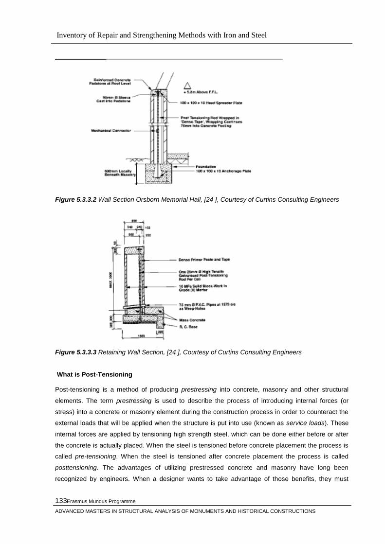
Inventory of Repair and Strengthening Methods with Iron and Steel
Erasmus Mundus Programme
ADVANCED MASTERS IN STRUCTURAL ANALYSIS OF MONUMENTS AND HISTORICAL CONSTRUCTIONS
133
Figure 5.3.3.2 Wall Section Orsborn Memorial Hall, [24 ], Courtesy of Curtins Consulting Engineers
Figure 5.3.3.3 Retaining Wall Section, [24 ], Courtesy of Curtins Consulting Engineers
What is Post-Tensioning
Post-tensioning is a method of producing prestressing into concrete, masonry and other structural
elements. The term prestressing is used to describe the process of introducing internal forces (or
stress) into a concrete or masonry element during the construction process in order to counteract the
external loads that will be applied when the structure is put into use (known as service loads). These
internal forces are applied by tensioning high strength steel, which can be done either before or after
the concrete is actually placed. When the steel is tensioned before concrete placement the process is
called pre-tensioning. When the steel is tensioned after concrete placement the process is called
posttensioning. The advantages of utilizing prestressed concrete and masonry have long been
recognized by engineers. When a designer wants to take advantage of those benefits, they must
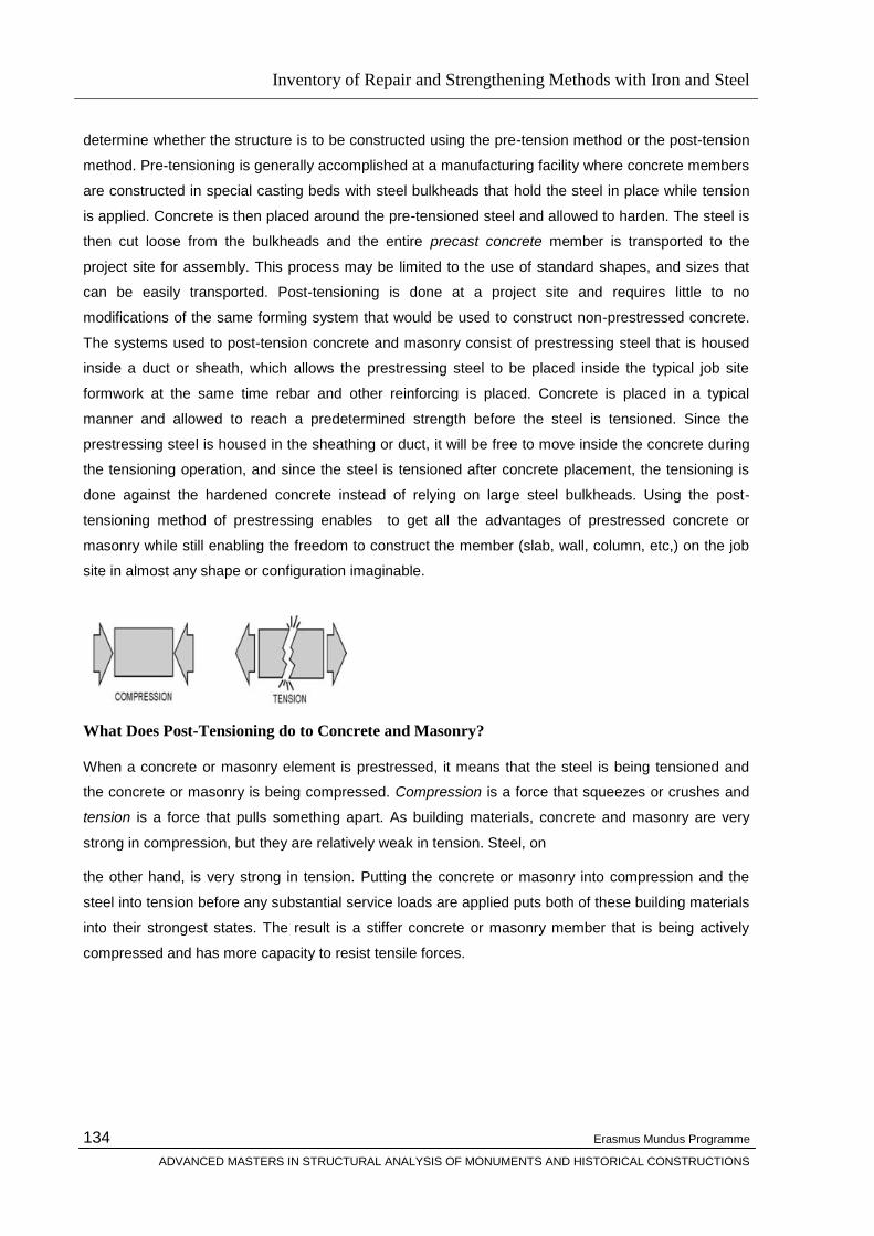
Inventory of Repair and Strengthening Methods with Iron and Steel
Erasmus Mundus Programme
ADVANCED MASTERS IN STRUCTURAL ANALYSIS OF MONUMENTS AND HISTORICAL CONSTRUCTIONS
134
determine whether the structure is to be constructed using the pre-tension method or the post-tension
method. Pre-tensioning is generally accomplished at a manufacturing facility where concrete members
are constructed in special casting beds with steel bulkheads that hold the steel in place while tension
is applied. Concrete is then placed around the pre-tensioned steel and allowed to harden. The steel is
then cut loose from the bulkheads and the entire precast concrete member is transported to the
project site for assembly. This process may be limited to the use of standard shapes, and sizes that
can be easily transported. Post-tensioning is done at a project site and requires little to no
modifications of the same forming system that would be used to construct non-prestressed concrete.
The systems used to post-tension concrete and masonry consist of prestressing steel that is housed
inside a duct or sheath, which allows the prestressing steel to be placed inside the typical job site
formwork at the same time rebar and other reinforcing is placed. Concrete is placed in a typical
manner and allowed to reach a predetermined strength before the steel is tensioned. Since the
prestressing steel is housed in the sheathing or duct, it will be free to move inside the concrete during
the tensioning operation, and since the steel is tensioned after concrete placement, the tensioning is
done against the hardened concrete instead of relying on large steel bulkheads. Using the post-
tensioning method of prestressing enables to get all the advantages of prestressed concrete or
masonry while still enabling the freedom to construct the member (slab, wall, column, etc,) on the job
site in almost any shape or configuration imaginable.
What Does Post-Tensioning do to Concrete and Masonry?
When a concrete or masonry element is prestressed, it means that the steel is being tensioned and
the concrete or masonry is being compressed. Compression is a force that squeezes or crushes and
tension is a force that pulls something apart. As building materials, concrete and masonry are very
strong in compression, but they are relatively weak in tension. Steel, on
the other hand, is very strong in tension. Putting the concrete or masonry into compression and the
steel into tension before any substantial service loads are applied puts both of these building materials
into their strongest states. The result is a stiffer concrete or masonry member that is being actively
compressed and has more capacity to resist tensile forces.
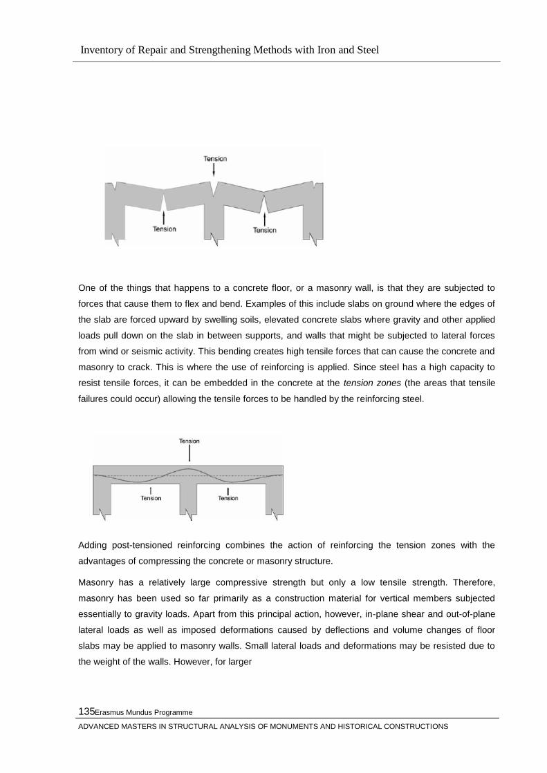
Inventory of Repair and Strengthening Methods with Iron and Steel
Erasmus Mundus Programme
ADVANCED MASTERS IN STRUCTURAL ANALYSIS OF MONUMENTS AND HISTORICAL CONSTRUCTIONS
135
One of the things that happens to a concrete floor, or a masonry wall, is that they are subjected to
forces that cause them to flex and bend. Examples of this include slabs on ground where the edges of
the slab are forced upward by swelling soils, elevated concrete slabs where gravity and other applied
loads pull down on the slab in between supports, and walls that might be subjected to lateral forces
from wind or seismic activity. This bending creates high tensile forces that can cause the concrete and
masonry to crack. This is where the use of reinforcing is applied. Since steel has a high capacity to
resist tensile forces, it can be embedded in the concrete at the tension zones (the areas that tensile
failures could occur) allowing the tensile forces to be handled by the reinforcing steel.
Adding post-tensioned reinforcing combines the action of reinforcing the tension zones with the
advantages of compressing the concrete or masonry structure.
Masonry has a relatively large compressive strength but only a low tensile strength. Therefore,
masonry has been used so far primarily as a construction material for vertical members subjected
essentially to gravity loads. Apart from this principal action, however, in-plane shear and out-of-plane
lateral loads as well as imposed deformations caused by deflections and volume changes of floor
slabs may be applied to masonry walls. Small lateral loads and deformations may be resisted due to
the weight of the walls. However, for larger

Inventory of Repair and Strengthening Methods with Iron and Steel
Erasmus Mundus Programme
ADVANCED MASTERS IN STRUCTURAL ANALYSIS OF MONUMENTS AND HISTORICAL CONSTRUCTIONS
136
lateral loads, walls with low axial loads exhibit a poor cracking behavior and a low strength. To
overcome these disadvantages, masonry may be post-tensioned. Post-tensioning offers the possibility
to actively introduce any desired level of axial load in a wall to enhance strength, performance, and
durability of masonry structures. The prestressing steel helps avoiding brittle tensile failure modes of
masonry walls and offers major advantages for the connection of vertical and horizontal members in
precast construction. Existing structures may be strengthened by prestressing to comply with recent
code requirements for lateral loading; in particular, seismic areas.
Materials and Equipment used in Post-Tensioning?
The basic element of a post-tensioning system is called a tendon. A post-tensioning tendon is made
up of one or more pieces of prestressing steel, coated with a protective coating,
and housed inside of a duct or sheathing. A tendon will have anchors on each end to transmit the
forces into the structure. Long tendons may also have intermediate anchors along their length. The
prestressing steel can be a high strength steel strand (typical in horizontal applications) or a high
strength steel bar (typical in vertical applications). Prestressing steel is manufactured to applicable
ASTM requirements. Typical strand sizes are 0.50 in. and 0.60 in. diameters, and bar sizes can
typically range from 1 in. to 2.5 in.
Tension is applied to prestressing steel by using a hydraulic stressing jack. The jack bears against one
of the anchors that is embedded in the concrete and pulls the steel to a predetermined force. As the
tensioning is occurring, the steel is being elongated, and the concrete or masonry element is being
compressed. When the proper tensioning force is reached, the prestressing steel is anchored in place.
The anchors are designed to provide a permanent mechanical connection, forever keeping the steel in
tension, and the concrete in compression.
The duct or sheathing that houses the prestressing steel provides one layer of corrosion protection. A
tendon with a duct that contains multiple pieces of prestressing steel strand is commonly called a
multistrand tendon, and a tendon in which a single prestressing steel strand is covered in a plastic
sheathing is commonly referred to as a monostrand tendon. Inside the duct or sheathing, the
prestressing steel is covered in a protective coating that provides another level of corrosion protection.
This coating can be a specially formulated type of grease, or it can be a specially designed type of

Inventory of Repair and Strengthening Methods with Iron and Steel
Erasmus Mundus Programme
ADVANCED MASTERS IN STRUCTURAL ANALYSIS OF MONUMENTS AND HISTORICAL CONSTRUCTIONS
137
grout. When grease is used, the prestressing steel is permanently free to move relative to the
sheathing and the tendon is referred to as an unbonded tendon. When grout is used, the steel is
permanently bonded to the sheathing and is referred to as a bonded tendon.
The hydraulic jacks used to tension the post-tensioning tendons range from compact 60 lb jacks used
to stress monostrand tendons and small bar tendons, to very large jacks requiring special hoisting
equipment, used to simultaneously tension all of the strands in large multistrand tendons.
5.3.4 Strengthening of Historic Buildings with Post-Tensioning
Post-tensioning of masonry structures means the combination of a relatively new technique with an
old material for strengthening purposes which requires several issues to be considered. The major
concern is the correct evaluation of the properties of masonry. Masonry structures have been known
to last for thousands of years, yet many older structures are condemned because they do not meet
current loading requirements or their durability is questioned, often because of improper maintenance
practices in the past. Masonry is not a homogeneous material which lends itself to simple elastic
analysis which generations of engineers have used for steel and concrete. New methods of analysis
enable the full potential of masonry to be realized.
Although several methods exist for determining the real characteristic of masonry, it is not possible to
use properly each of them in any situation. Another concern relates to the problem of the lack of exact
rules and formulas for the design of prestressed tendons.
The codification of post-tensioning masonry has only begun recently (e.g. MSJC 1999). Much
research has been conducted in the last decade on post-tensioning masonry worldwide (e.g. Lissel
and Shrive 2003, Rosenboom and Kowalsky 2003, Schultz et al. 2003, Laursen et al. 2002).
The successfull application of post-tensioning rely on the proper execution of the following:
Determination & assesment of the real properties of the masonary and the building
Appropriate design according to the relevant codes
Proper application of post-tensioning

Inventory of Repair and Strengthening Methods with Iron and Steel
Erasmus Mundus Programme
ADVANCED MASTERS IN STRUCTURAL ANALYSIS OF MONUMENTS AND HISTORICAL CONSTRUCTIONS
138
Figure 5.3.3.4 Strengthening of walls by prestressing
A Horizontal compression state induced by horizontal tendons can be used to increase the shear
strength of walls. Moreover this will also improve considerably the connections of orthogonal walls,
Figure 5.2.2.4 The easiest way of affecting the precompression is to place two steel rods on the two
sides of the wall and strengthening them by turnbuckles. Note that good effects can be obtained by
slight horizontal prestressing (about 0.1 MPa) on the vertical section of the wall. Prestressing is also
useful to strengthen spandrel beam between two rows of openings in the case no rigid stab exists.
External binding
Opposite parallel walls can be held to internal cross walls by prestressing bars as illustrated above,
the anchoring being done against horizontal steel channels instead of small steel plates. The steel

Inventory of Repair and Strengthening Methods with Iron and Steel
Erasmus Mundus Programme
ADVANCED MASTERS IN STRUCTURAL ANALYSIS OF MONUMENTS AND HISTORICAL CONSTRUCTIONS
139
channels running from one cross wall to the other will hold the walls together and improve the integral
box like action of the walls. The technique of covering the wall with steel mesh and mortar or micro-
concrete may be used only on the outside surface of external walls but maintaining continuity of steel
at the corners. This would strengthen the walls as well as bind them together. As a variation and for
economy in the use of materials, the covering may be in the form of vertical splints between openings
and horizontal bandages over spandrel walls at suitable number of points
only, Figure 5.2.2.5
Figure 5.3.3.5 Splint and bandage strengthening technique
Anchorage of post-tensioning in masonry is more complicated than in r.c. as masonry has a relatively
low compressive strength. The self-activating dead end can be encasing to continuous and heavy r.c.
foundation beams, constructed on either side of the wall bottom and connected well with it. At the top,
post-tensioning is anchored in the existing r.c. elements (Figure 5.3.3.5 (c)) or in a new precast r.c.
special beam or specially stiffened steel plates. Anchorage devices and plates are usually placed in a
recess of the surface, and covered later on with shotcrete or cement mortar. The requirement for
bottom anchorage penalizes considerably this retrofitting technique. Vertical post-tensioning resulting
in substantial improvement in wall ultimate behavior for both in-plane and out-of-plane; in addition, it
improves both cracking load and distribution. Rosenboom and Kowalsky (2003) show that for cavity
walls, the posttension grouted specimen has lateral resistance much higher (40%) than the ungrouted

Inventory of Repair and Strengthening Methods with Iron and Steel
Erasmus Mundus Programme
ADVANCED MASTERS IN STRUCTURAL ANALYSIS OF MONUMENTS AND HISTORICAL CONSTRUCTIONS
140
one. For grouted specimens, although to bond or not the bars have insignificant effect on lateral
resistance; the specimen who has un-bonded bars has higher lateral drift (70%) over the bonded
specimen. The un-bonded grouted specimen has a drift up to 6.5%. However, un-bonded post-tension
tendons may show low energy dissipation due to the lack of yielding of reinforcement (VSL 1990).
The effect of horizontal post-tensioning needs extensive experimental examination. Although some
basic calculations of principle stresses show that the horizontal posttensioning improves the
resistance, Page and Huizer (1994) experimental test did not proof these calculations. In a linear finite
element model, Karantoni and Faradis (1992) show that horizontal post-tensioning of spandrels did
not significantly improve the building behavior. In addition, they show that if horizontal and vertical
post-tensioning is combined together the resulting positive effect is higher than the sum of the
individual effects of the two directions post-tensioning. For bonded grouted post-tensioning the
ultimate tendon force may be determined assuming rigid bond and plane sections similar to design of
r.c. post-tensioning. Thus, the tendon will reach their yield force. For un-bonded post-tensioning the
tendon force will increase from service up to ultimate load depending on the deformations. This
increment in the tendon force may be estimated by applying rigid mechanisms. For short time behavior
and under the same post-tensioning force, strand configuration and amount has insignificant effect on
wall behavior (Al-Manaseer and Neis 1987).
Figure 5.3.3.5 (a) post-tensioning using FRP, (b) flexural crack in post-tension wall, (c) posttensioning jacking frame (ISIS)
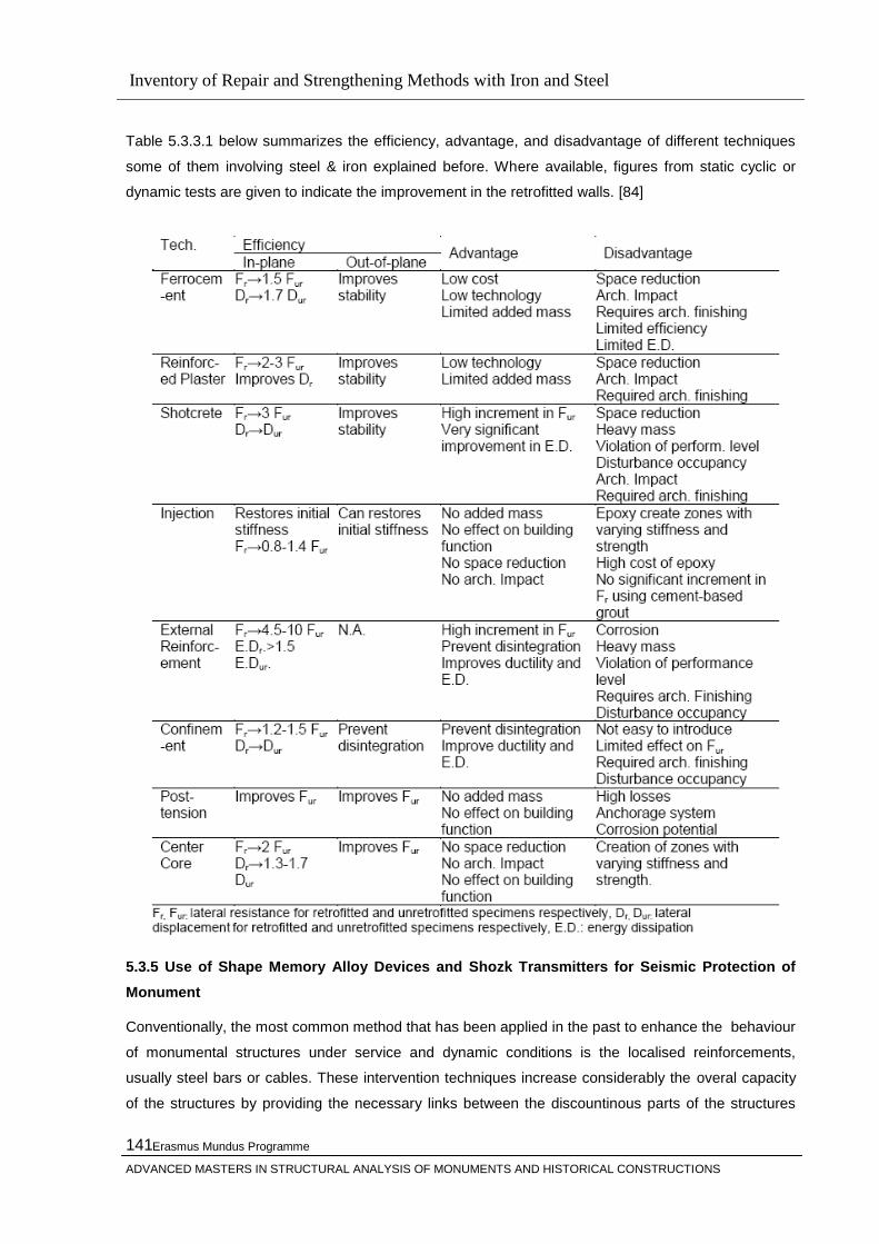
Inventory of Repair and Strengthening Methods with Iron and Steel
Erasmus Mundus Programme
ADVANCED MASTERS IN STRUCTURAL ANALYSIS OF MONUMENTS AND HISTORICAL CONSTRUCTIONS
141
Table 5.3.3.1 below summarizes the efficiency, advantage, and disadvantage of different techniques
some of them involving steel & iron explained before. Where available, figures from static cyclic or
dynamic tests are given to indicate the improvement in the retrofitted walls. [84]
5.3.5 Use of Shape Memory Alloy Devices and Shozk Transmitters for Seismic Protection of
Monument
Conventionally, the most common method that has been applied in the past to enhance the behaviour
of monumental structures under service and dynamic conditions is the localised reinforcements,
usually steel bars or cables. These intervention techniques increase considerably the overal capacity
of the structures by providing the necessary links between the discountinous parts of the structures
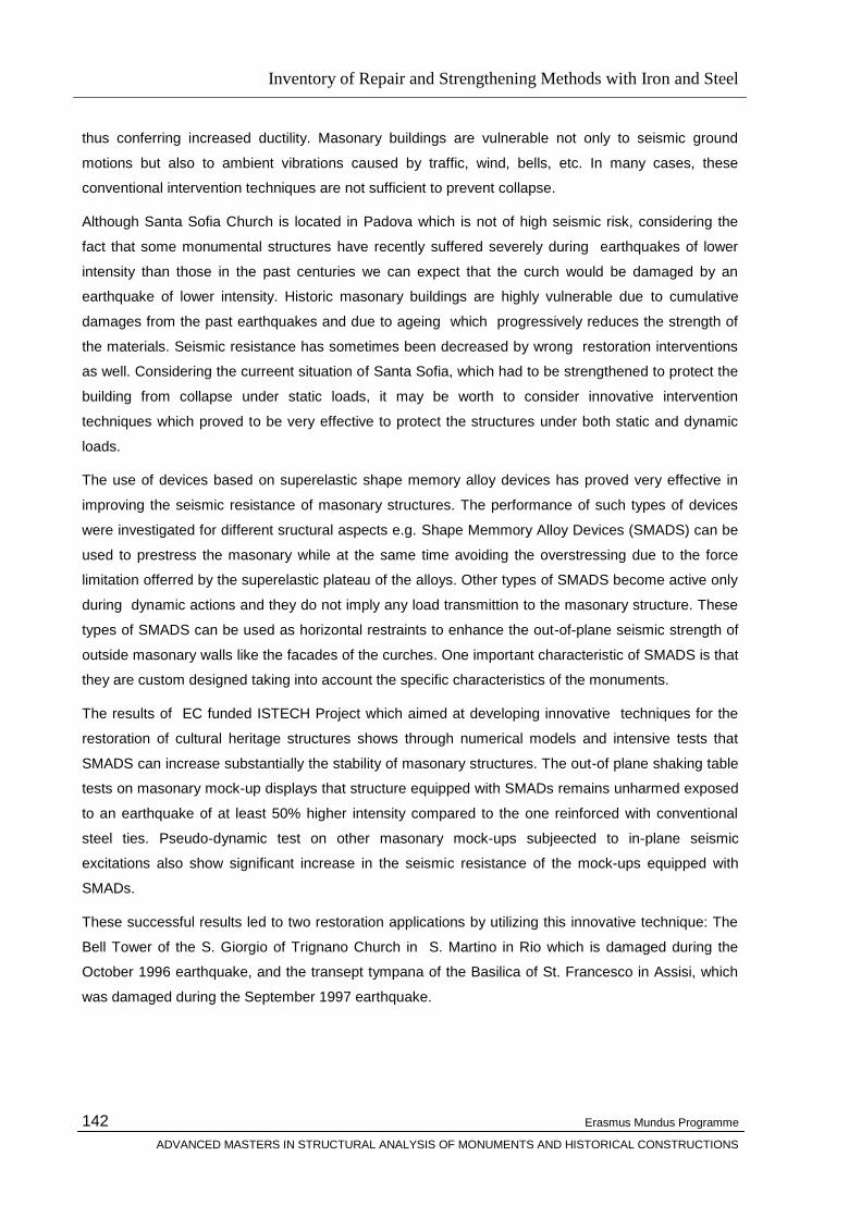
Inventory of Repair and Strengthening Methods with Iron and Steel
Erasmus Mundus Programme
ADVANCED MASTERS IN STRUCTURAL ANALYSIS OF MONUMENTS AND HISTORICAL CONSTRUCTIONS
142
thus conferring increased ductility. Masonary buildings are vulnerable not only to seismic ground
motions but also to ambient vibrations caused by traffic, wind, bells, etc. In many cases, these
conventional intervention techniques are not sufficient to prevent collapse.
Although Santa Sofia Church is located in Padova which is not of high seismic risk, considering the
fact that some monumental structures have recently suffered severely during earthquakes of lower
intensity than those in the past centuries we can expect that the curch would be damaged by an
earthquake of lower intensity. Historic masonary buildings are highly vulnerable due to cumulative
damages from the past earthquakes and due to ageing which progressively reduces the strength of
the materials. Seismic resistance has sometimes been decreased by wrong restoration interventions
as well. Considering the curreent situation of Santa Sofia, which had to be strengthened to protect the
building from collapse under static loads, it may be worth to consider innovative intervention
techniques which proved to be very effective to protect the structures under both static and dynamic
loads.
The use of devices based on superelastic shape memory alloy devices has proved very effective in
improving the seismic resistance of masonary structures. The performance of such types of devices
were investigated for different sructural aspects e.g. Shape Memmory Alloy Devices (SMADS) can be
used to prestress the masonary while at the same time avoiding the overstressing due to the force
limitation offerred by the superelastic plateau of the alloys. Other types of SMADS become active only
during dynamic actions and they do not imply any load transmittion to the masonary structure. These
types of SMADS can be used as horizontal restraints to enhance the out-of-plane seismic strength of
outside masonary walls like the facades of the curches. One important characteristic of SMADS is that
they are custom designed taking into account the specific characteristics of the monuments.
The results of EC funded ISTECH Project which aimed at developing innovative techniques for the
restoration of cultural heritage structures shows through numerical models and intensive tests that
SMADS can increase substantially the stability of masonary structures. The out-of plane shaking table
tests on masonary mock-up displays that structure equipped with SMADs remains unharmed exposed
to an earthquake of at least 50% higher intensity compared to the one reinforced with conventional
steel ties. Pseudo-dynamic test on other masonary mock-ups subjeected to in-plane seismic
excitations also show significant increase in the seismic resistance of the mock-ups equipped with
SMADs.
These successful results led to two restoration applications by utilizing this innovative technique: The
Bell Tower of the S. Giorgio of Trignano Church in S. Martino in Rio which is damaged during the
October 1996 earthquake, and the transept tympana of the Basilica of St. Francesco in Assisi, which
was damaged during the September 1997 earthquake.
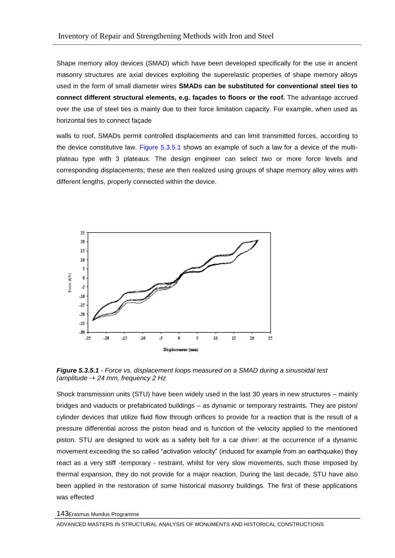
Inventory of Repair and Strengthening Methods with Iron and Steel
Erasmus Mundus Programme
ADVANCED MASTERS IN STRUCTURAL ANALYSIS OF MONUMENTS AND HISTORICAL CONSTRUCTIONS
143
Shape memory alloy devices (SMAD) which have been developed specifically for the use in ancient
masonry structures are axial devices exploiting the superelastic properties of shape memory alloys
used in the form of small diameter wires SMADs can be substituted for conventional steel ties to
connect different structural elements, e.g. façades to floors or the roof. The advantage accrued
over the use of steel ties is mainly due to their force limitation capacity. For example, when used as
horizontal ties to connect façade
walls to roof, SMADs permit controlled displacements and can limit transmitted forces, according to
the device constitutive law. Figure 5.3.5.1 shows an example of such a law for a device of the multi-
plateau type with 3 plateaux. The design engineer can select two or more force levels and
corresponding displacements; these are then realized using groups of shape memory alloy wires with
different lengths, properly connected within the device.
Figure 5.3.5.1 - Force vs. displacement loops measured on a SMAD during a sinusoidal test (amplitude -+ 24 mm, frequency 2 Hz
Shock transmission units (STU) have been widely used in the last 30 years in new structures – mainly
bridges and viaducts or prefabricated buildings – as dynamic or temporary restraints. They are piston/
cylinder devices that utilize fluid flow through orifices to provide for a reaction that is the result of a
pressure differential across the piston head and is function of the velocity applied to the mentioned
piston. STU are designed to work as a safety belt for a car driver: at the occurrence of a dynamic
movement exceeding the so called ―activation velocity‖ (induced for example from an earthquake) they
react as a very stiff -temporary - restraint, whilst for very slow movements, such those imposed by
thermal expansion, they do not provide for a major reaction. During the last decade, STU have also
been applied in the restoration of some historical masonry buildings. The first of these applications
was effected
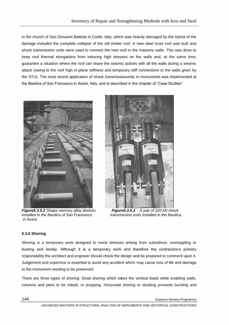
Inventory of Repair and Strengthening Methods with Iron and Steel
Erasmus Mundus Programme
ADVANCED MASTERS IN STRUCTURAL ANALYSIS OF MONUMENTS AND HISTORICAL CONSTRUCTIONS
144
in the church of San Giovanni Battista in Carife, Italy, which was heavily damaged by the Irpinia of the
damage included the complete collapse of the old timber roof. A new steel truss roof was built and
shock transmission units were used to connect the new roof to the masonry walls. This was done to
keep roof thermal elongations from inducing high stresses on the walls and, at the same time,
guarantee a situation where the roof can share the seismic actions with all the walls during a seismic
attack (owing to the roof high in-plane stiffness and temporary stiff connections to the walls given by
the STU). The most recent application of shock transmissionunits in monuments was implemented at
the Basilica of San Francesco in Assisi, Italy, and is described in the chapter of ―Case Studies‖.
Figure5.3.5.2 Shape memory alloy devices Figure5.3.5.3 - A pair of 220 kN shock installed in the Basilica of San Francesco transmission units installed in the Basilica. in Assisi.
5.3.6 Shoring
Shoring is a temporary work designed to resist stresses arising from subsidince, overtoppling or
busting and lanslip. Although it is a temporary work and therefore the contractors‘s primary
responsibility the architect and engineer should check the design and be prepared to comment upon it.
Judgement and experince is essential to avoid any accident which may cause loss of life and damage
to the monument needing to be preserved.
There are three types of shoring: Dead shoring which takes the vertical loads while enabling walls,
columns and piers to be rebuilt, or propping. Horizontal shoring or strutting prevents bursting and
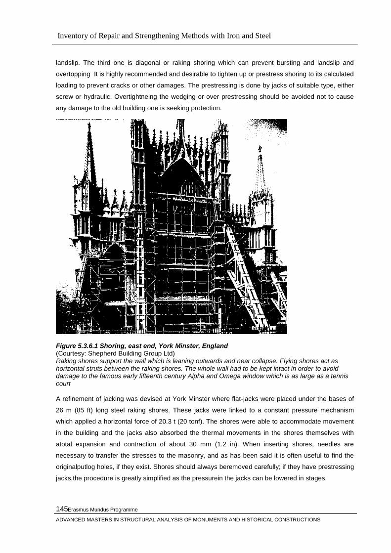
Inventory of Repair and Strengthening Methods with Iron and Steel
Erasmus Mundus Programme
ADVANCED MASTERS IN STRUCTURAL ANALYSIS OF MONUMENTS AND HISTORICAL CONSTRUCTIONS
145
landslip. The third one is diagonal or raking shoring which can prevent bursting and landslip and
overtopping It is highly recommended and desirable to tighten up or prestress shoring to its calculated
loading to prevent cracks or other damages. The prestressing is done by jacks of suitable type, either
screw or hydraulic. Overtightneing the wedging or over prestressing should be avoided not to cause
any damage to the old building one is seeking protection.
Figure 5.3.6.1 Shoring, east end, York Minster, England (Courtesy: Shepherd Building Group Ltd) Raking shores support the wall which is leaning outwards and near collapse. Flying shores act as horizontal struts between the raking shores. The whole wall had to be kept intact in order to avoid damage to the famous early fifteenth century Alpha and Omega window which is as large as a tennis court A refinement of jacking was devised at York Minster where flat-jacks were placed under the bases of
26 m (85 ft) long steel raking shores. These jacks were linked to a constant pressure mechanism
which applied a horizontal force of 20.3 t (20 tonf). The shores were able to accommodate movement
in the building and the jacks also absorbed the thermal movements in the shores themselves with
atotal expansion and contraction of about 30 mm (1.2 in). When inserting shores, needles are
necessary to transfer the stresses to the masonry, and as has been said it is often useful to find the
originalputlog holes, if they exist. Shores should always beremoved carefully; if they have prestressing
jacks,the procedure is greatly simplified as the pressurein the jacks can be lowered in stages.
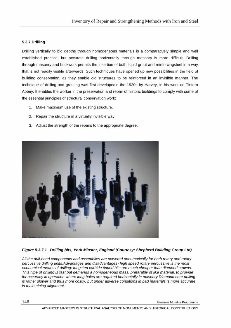
Inventory of Repair and Strengthening Methods with Iron and Steel
Erasmus Mundus Programme
ADVANCED MASTERS IN STRUCTURAL ANALYSIS OF MONUMENTS AND HISTORICAL CONSTRUCTIONS
146
5.3.7 Drilling
Drilling vertically to big depths through homogeneous materials is a comparatively simple and well
established practice, but accurate drilling horizontally through masonry is more difficult. Drilling
through masonry and brickwork permits the insertion of both liquid grout and reinforcingsteel in a way
that is not readily visible afterwards. Such techniques have opened up new possibilities in the field of
building conservation, as they enable old structures to be reinforced in an invisible manner. The
technique of drilling and grouting was first developedin the 1920s by Harvey, in his work on Tintern
Abbey. It enables the worker in the preservation and repair of historic buildings to comply with some of
the essential principles of structural conservation work:
1. Make maximum use of the existing structure.
2. Repair the structure in a virtually invisible way.
3. Adjust the strength of the repairs to the appropriate degree.
Figure 5.3.7.1 Drilling bits, York Minster, England (Courtesy: Shepherd Building Group Ltd) All the drill-bead components and assemblies are powered pneumatically for both rotary and rotary percussive drilling units.Advantages and disadvantages- high speed rotary percussive is the most economical means of drilling: tungsten carbide tipped bits are much cheaper than diamond crowns. This type of drilling is fast but demands a homogeneous mass, prefarably of like material, to provide for accuracy in operation where long holes are required horizontally in masonry.Diamond core drilling is rather slower and thus more costly, but under adverse conditions in bad materials is more accurate in maintaining alignment.
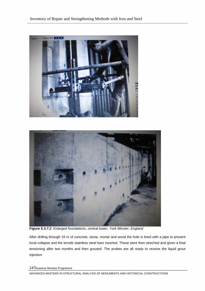
Inventory of Repair and Strengthening Methods with Iron and Steel
Erasmus Mundus Programme
ADVANCED MASTERS IN STRUCTURAL ANALYSIS OF MONUMENTS AND HISTORICAL CONSTRUCTIONS
147
Figure 5.3.7.2. Enlarged foundations, central tower, York Minster, England
After drilling through 15 m of concrete, stone, mortar and wood the hole is lined with a pipe to prevent
local collapse and the tensile stainless steel bars inserted. These were then streched and given a final
tensioning after two months and then grouted. The probes are all ready to receive the liquid grout
injection.
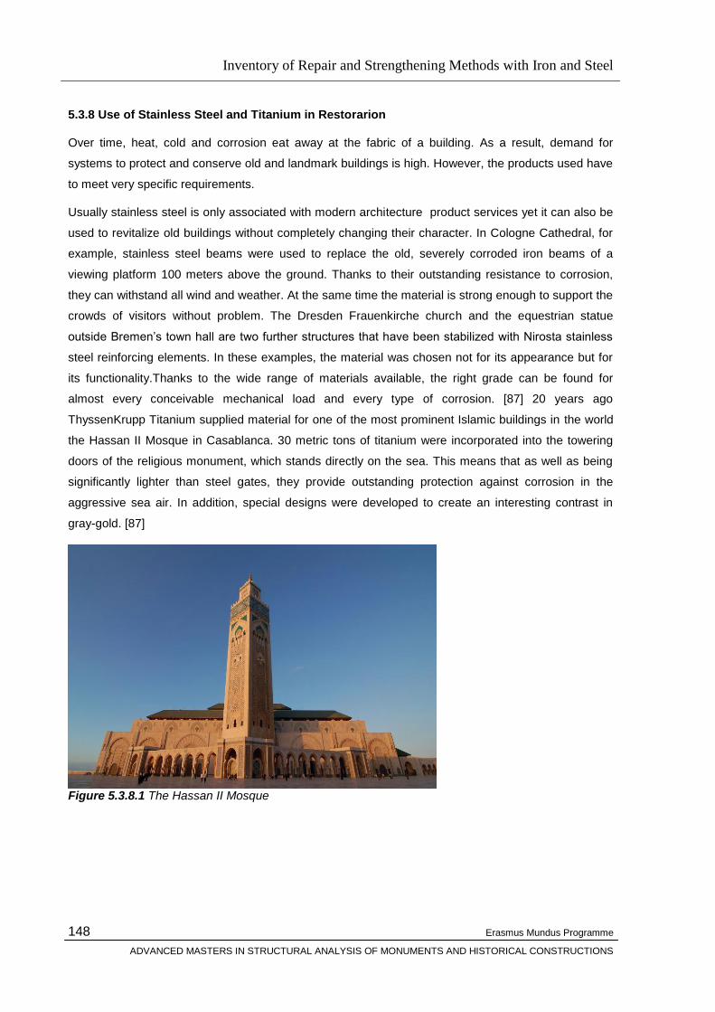
Inventory of Repair and Strengthening Methods with Iron and Steel
Erasmus Mundus Programme
ADVANCED MASTERS IN STRUCTURAL ANALYSIS OF MONUMENTS AND HISTORICAL CONSTRUCTIONS
148
5.3.8 Use of Stainless Steel and Titanium in Restorarion
Over time, heat, cold and corrosion eat away at the fabric of a building. As a result, demand for
systems to protect and conserve old and landmark buildings is high. However, the products used have
to meet very specific requirements.
Usually stainless steel is only associated with modern architecture product services yet it can also be
used to revitalize old buildings without completely changing their character. In Cologne Cathedral, for
example, stainless steel beams were used to replace the old, severely corroded iron beams of a
viewing platform 100 meters above the ground. Thanks to their outstanding resistance to corrosion,
they can withstand all wind and weather. At the same time the material is strong enough to support the
crowds of visitors without problem. The Dresden Frauenkirche church and the equestrian statue
outside Bremen‘s town hall are two further structures that have been stabilized with Nirosta stainless
steel reinforcing elements. In these examples, the material was chosen not for its appearance but for
its functionality.Thanks to the wide range of materials available, the right grade can be found for
almost every conceivable mechanical load and every type of corrosion. [87] 20 years ago
ThyssenKrupp Titanium supplied material for one of the most prominent Islamic buildings in the world
the Hassan II Mosque in Casablanca. 30 metric tons of titanium were incorporated into the towering
doors of the religious monument, which stands directly on the sea. This means that as well as being
significantly lighter than steel gates, they provide outstanding protection against corrosion in the
aggressive sea air. In addition, special designs were developed to create an interesting contrast in
gray-gold. [87]
Figure 5.3.8.1 The Hassan II Mosque

Inventory of Repair and Strengthening Methods with Iron and Steel
Erasmus Mundus Programme
ADVANCED MASTERS IN STRUCTURAL ANALYSIS OF MONUMENTS AND HISTORICAL CONSTRUCTIONS
149
The Mosque, the second largest in the world after the Masjid al-Haram in Mecca, was designed by the
French architect Michel Pinseau. It looks out onto the Atlantic and its sheer size almost overwhelms
both city and coastline.
Titanium has been performing an important behind-the-scenes task in the Acropolis in Athens for
decades. The steel bars originally used for restoration work had to be replaced with titanium because
only titanium has the corrosion resistance needed to protect the marble of the world-famous temple
columns from decay. [87]
Figure 5.3.8.2 Titanium Cramp Replacing Acropolis The inadequacy of earlier interventions in the Acropolis monuments is due mainly to the replacement
of the ancient iron reinforcements and the use of uncoated iron elements to join together fragmented
architectural members or to reinforce the resistance of others. Thanks to the strength and durability of
stainless materials, monument conservation is a highly promising application for the future. Further
projects are planned or already under way: For example, ThyssenKrupp Titanium supplied material for
the restoration of the roof of the famous Basilica di San Francesco in Assisi, which was destroyed by
an earthquake in 1997. A titanium structure is also to be used to stabilize the foundations of the
Campanile di San Marco in Venice. In addition, the dome of Berlin Cathedral, known as the ―lantern‖,
is to be restored using material from ThyssenKrupp Nirosta.
Figure 5.3.8.3 Campanile di San Marco in Venice

Inventory of Repair and Strengthening Methods with Iron and Steel
Erasmus Mundus Programme
ADVANCED MASTERS IN STRUCTURAL ANALYSIS OF MONUMENTS AND HISTORICAL CONSTRUCTIONS
150
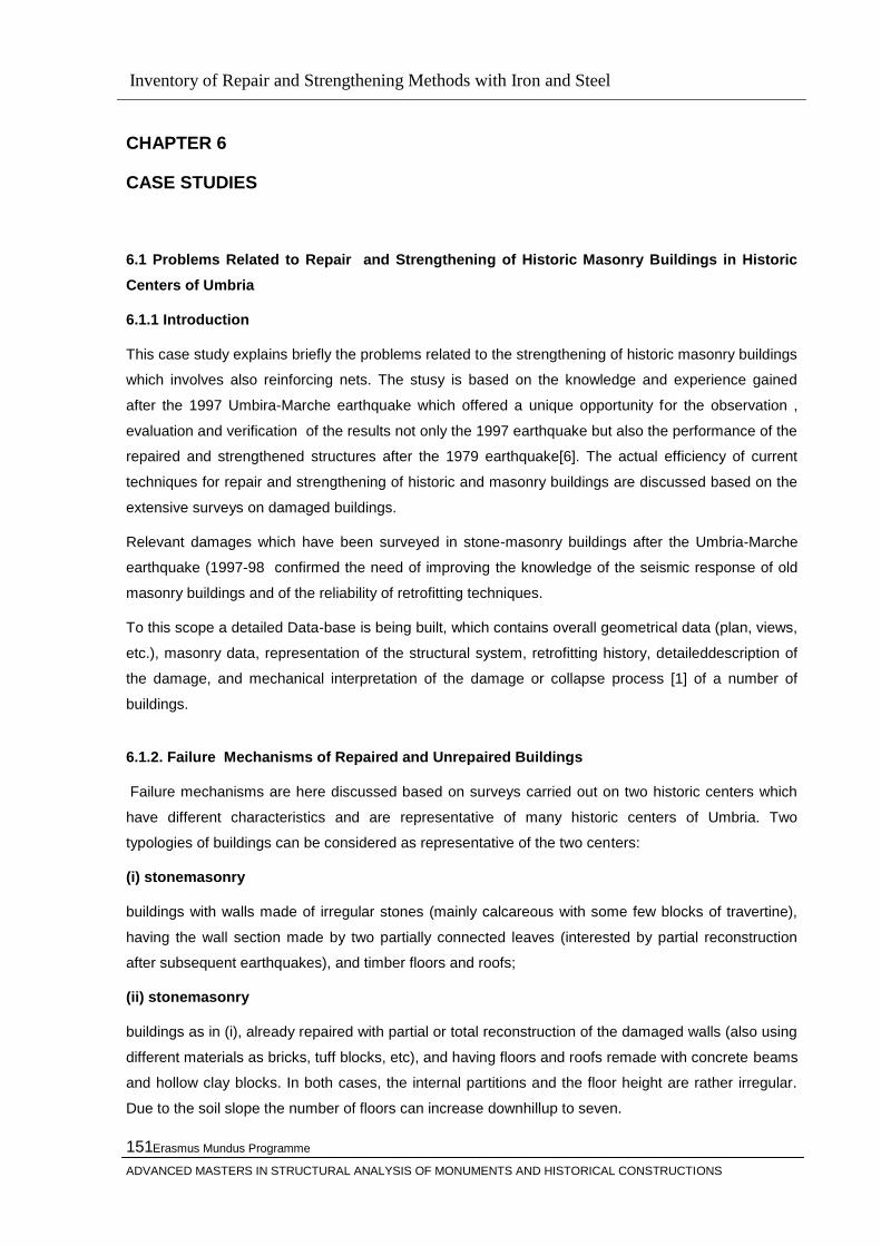
Inventory of Repair and Strengthening Methods with Iron and Steel
Erasmus Mundus Programme
ADVANCED MASTERS IN STRUCTURAL ANALYSIS OF MONUMENTS AND HISTORICAL CONSTRUCTIONS
151
CHAPTER 6
CASE STUDIES
6.1 Problems Related to Repair and Strengthening of Historic Masonry Buildings in Historic
Centers of Umbria
6.1.1 Introduction
This case study explains briefly the problems related to the strengthening of historic masonry buildings
which involves also reinforcing nets. The stusy is based on the knowledge and experience gained
after the 1997 Umbira-Marche earthquake which offered a unique opportunity for the observation ,
evaluation and verification of the results not only the 1997 earthquake but also the performance of the
repaired and strengthened structures after the 1979 earthquake[6]. The actual efficiency of current
techniques for repair and strengthening of historic and masonry buildings are discussed based on the
extensive surveys on damaged buildings.
Relevant damages which have been surveyed in stone-masonry buildings after the Umbria-Marche
earthquake (1997-98 confirmed the need of improving the knowledge of the seismic response of old
masonry buildings and of the reliability of retrofitting techniques.
To this scope a detailed Data-base is being built, which contains overall geometrical data (plan, views,
etc.), masonry data, representation of the structural system, retrofitting history, detaileddescription of
the damage, and mechanical interpretation of the damage or collapse process [1] of a number of
buildings.
6.1.2. Failure Mechanisms of Repaired and Unrepaired Buildings
Failure mechanisms are here discussed based on surveys carried out on two historic centers which
have different characteristics and are representative of many historic centers of Umbria. Two
typologies of buildings can be considered as representative of the two centers:
(i) stonemasonry
buildings with walls made of irregular stones (mainly calcareous with some few blocks of travertine),
having the wall section made by two partially connected leaves (interested by partial reconstruction
after subsequent earthquakes), and timber floors and roofs;
(ii) stonemasonry
buildings as in (i), already repaired with partial or total reconstruction of the damaged walls (also using
different materials as bricks, tuff blocks, etc), and having floors and roofs remade with concrete beams
and hollow clay blocks. In both cases, the internal partitions and the floor height are rather irregular.
Due to the soil slope the number of floors can increase downhillup to seven.

Inventory of Repair and Strengthening Methods with Iron and Steel
Erasmus Mundus Programme
ADVANCED MASTERS IN STRUCTURAL ANALYSIS OF MONUMENTS AND HISTORICAL CONSTRUCTIONS
152
6.1.2.1 Isolated buildings (Montesanto)
In the case of isolated buildings four main mechanisms were identified for non repaired or badly
repaired structures:
1. Out of plane of loadbearing walls with local or total collapse of the facades or of the corners, or
large deformation of the walls. This mechanism is due to the lack of connection between orthogonal
walls and between walls and floors or roofs (e.g absence of tie rods) and to the presence of large
openings .
2. Out of plane mechanisms with local or large failures of the upper part of the walls and collapses of
parapets, cornices and spandrels . Large diffused cracks appear where beams are settled, and local
collapses occur due to the high stresses caused by the hammering. Due to the thrust of the roof and
to the absence of connection between the roof and the masonry (also due to the masonry
heterogeneity) the detachment of concrete ring beams was also observed .
3. Wall disconnection and leaf separation with local or global failures. The presence of
inhomogeneities in the wall, the lack of connection between the leaves of multiple leaf walls, the filling
of openings without good connection between the old and the new parts or the use of different types of
materials can be the causes of such mechanism.
4. In plane mechanisms due to shear stresses with diagonal cracks of piers and walls at the different
floors. They are mainly due to: bad positioned openings, differential stiffness of the walls between
openings, presence of weak lintels (Figure. 6.1.5).
6.1.2.2 Row houses (Roccanolfi)
An accurate study is still ongoing in the case of Roccanolfi, in order to better define and understand
the typical mechanisms of large blocks of houses where the buildings are attached together forming a
sort of curtain and built on steep slopes of the soil. To this aim groups of buildings were identified as
building blocks. The damage of each block has been studied and surveyed, also adopting axonometric
representations which can better show the different levels of the soil. This study allowed to stress out
the typical mechanisms of failure of the cases when buildings are tied together along the streets and in
differential levels. In all the blocks, the first and the last building are badly damaged by local collapses
and large cracks . When the collapses occur in the internal part of the blocks they always interest the
non repaired buildings adjacent to the repaired ones In the central part of the building curtains with
the presence of decayed floors and roofs large continuous deformations and out of plumb of the walls
were detected. Moreover, due to the hammering of the two blocks cracks and damages appear where
vaulted passages connect two blocks of buildings . This phenomenon is more clear when only one of
the blocks was repaired.
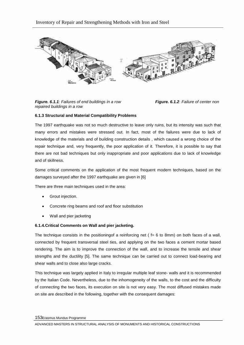
Inventory of Repair and Strengthening Methods with Iron and Steel
Erasmus Mundus Programme
ADVANCED MASTERS IN STRUCTURAL ANALYSIS OF MONUMENTS AND HISTORICAL CONSTRUCTIONS
153
Figure. 6.1.1: Failures of end buildings in a row Figure. 6.1.2: Failure of center non repaired buildings in a row
6.1.3 Structural and Material Compatibility Problems
The 1997 earthquake was not so much destructive to leave only ruins, but its intensity was such that
many errors and mistakes were stressed out. In fact, most of the failures were due to lack of
knowledge of the materials and of building construction details , which caused a wrong choice of the
repair technique and, very frequently, the poor application of it. Therefore, it is possible to say that
there are not bad techniques but only inappropriate and poor applications due to lack of knowledge
and of skillness.
Some critical comments on the application of the most frequent modern techniques, based on the
damages surveyed after the 1997 earthquake are given in [6]
There are three main techniques used in the area:
Grout injection.
Concrete ring beams and roof and floor substitution
Wall and pier jacketing
6.1.4.Critical Comments on Wall and pier jacketing.
The technique consists in the positioningof a reinforcing net ( f= 6 to 8mm) on both faces of a wall,
connected by frequent transversal steel ties, and applying on the two faces a cement mortar based
rendering. The aim is to improve the connection of the wall, and to increase the tensile and shear
strengths and the ductility [5]. The same technique can be carried out to connect load-bearing and
shear walls and to close also large cracks.
This technique was largely applied in Italy to irregular multiple leaf stone- walls and it is recommended
by the Italian Code. Nevertheless, due to the inhomogeneity of the walls, to the cost and the difficulty
of connecting the two faces, its execution on site is not very easy. The most diffused mistakes made
on site are described in the following, together with the consequent damages:
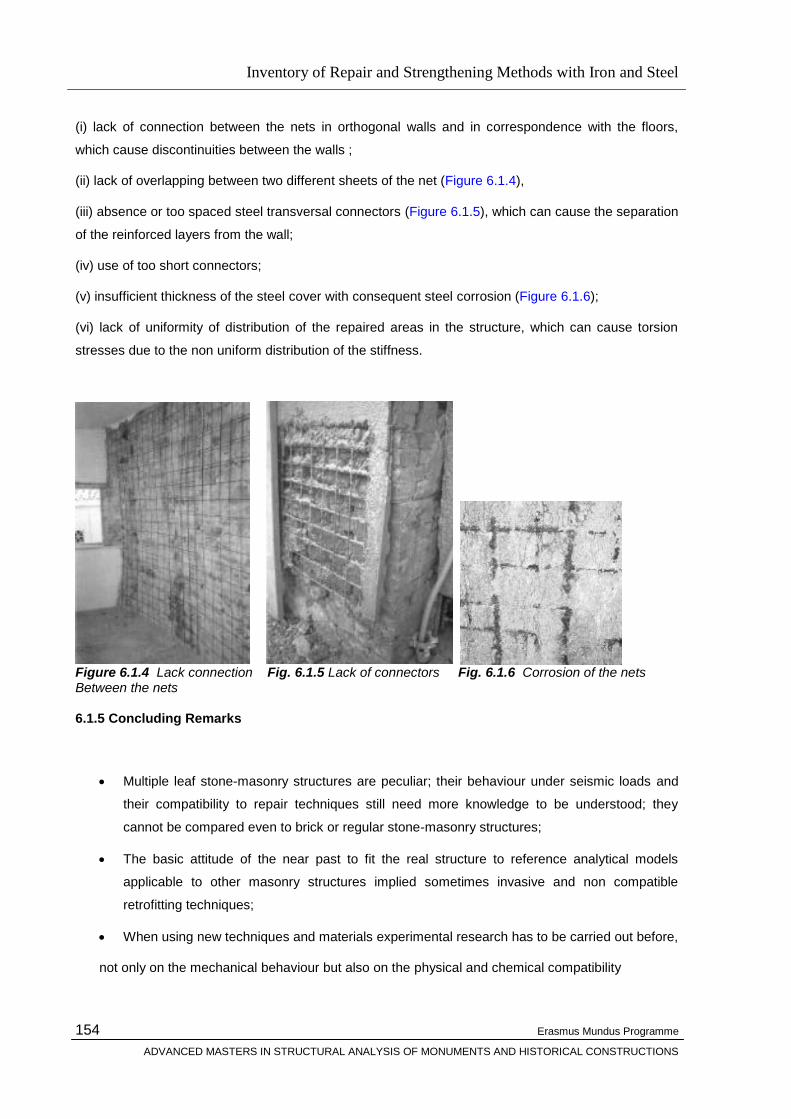
Inventory of Repair and Strengthening Methods with Iron and Steel
Erasmus Mundus Programme
ADVANCED MASTERS IN STRUCTURAL ANALYSIS OF MONUMENTS AND HISTORICAL CONSTRUCTIONS
154
(i) lack of connection between the nets in orthogonal walls and in correspondence with the floors,
which cause discontinuities between the walls ;
(ii) lack of overlapping between two different sheets of the net (Figure 6.1.4),
(iii) absence or too spaced steel transversal connectors (Figure 6.1.5), which can cause the separation
of the reinforced layers from the wall;
(iv) use of too short connectors;
(v) insufficient thickness of the steel cover with consequent steel corrosion (Figure 6.1.6);
(vi) lack of uniformity of distribution of the repaired areas in the structure, which can cause torsion
stresses due to the non uniform distribution of the stiffness.
Figure 6.1.4 Lack connection Fig. 6.1.5 Lack of connectors Fig. 6.1.6 Corrosion of the nets Between the nets 6.1.5 Concluding Remarks
Multiple leaf stone-masonry structures are peculiar; their behaviour under seismic loads and
their compatibility to repair techniques still need more knowledge to be understood; they
cannot be compared even to brick or regular stone-masonry structures;
The basic attitude of the near past to fit the real structure to reference analytical models
applicable to other masonry structures implied sometimes invasive and non compatible
retrofitting techniques;
When using new techniques and materials experimental research has to be carried out before,
not only on the mechanical behaviour but also on the physical and chemical compatibility
Inventory of Repair and Strengthening Methods with Iron and Steel
Erasmus Mundus Programme
ADVANCED MASTERS IN STRUCTURAL ANALYSIS OF MONUMENTS AND HISTORICAL CONSTRUCTIONS
155
with the existing structure and materials.
As regards compatibility problems, it is worth noting that repair techniques were used in the past
centuries and the present ones are sometimes only a reproposal of them using modern materials,
which can be incompatible with the existing ones. A better knowledge of the traditional techniques and
new research to apply them in a modern way will be one of the major issues of the future research of
the authors in this field. At present, in fact, very few research has been carried out on the behaviour of
rubble and multiple leaf stone structures before choosing the appropriate repair techniques .
6.2. French Pantheon- The Causes of Structural Disorders of Soufflot‟s Pantheon in Paris
6.2.1 General
The French Panthéon (Figure 6.2.1), started by Soufflot in 1756 as the biggest church in Paris,
dedicated to Sainte Genevieve, patron saint of the town, and finished by Rondelet in 1790, is,
probably, the first building to be calculated with modern methods of structural engineering. The need
for these calculations was the consequence of the adoption of an innovative building technique (the
reinforced stone masonry) and of the reduced dimensions of wall structures, that did not follow the
classical building rules. Still in the design phase, the first objections aroused from the architects linked
to the old academic building tradition, particularly from Pierre Patte [6], because the structures did not
respect the canonical proportions: pillars too slender, domes masonry too thin, windows too large. To
answer this first campaign of polemics, Jacques-Germain Soufflot and Emiland-Marie Gauthey,
director of the prestigious ―École des ponts et chaussés‖, carried out the first systematic compression
tests on stone specimens and the first calculations [3,5], demonstrating that the pillars had a cross
section large enough to sustain the weight of the domes considering a centred load (Figure 6.2.2.2).
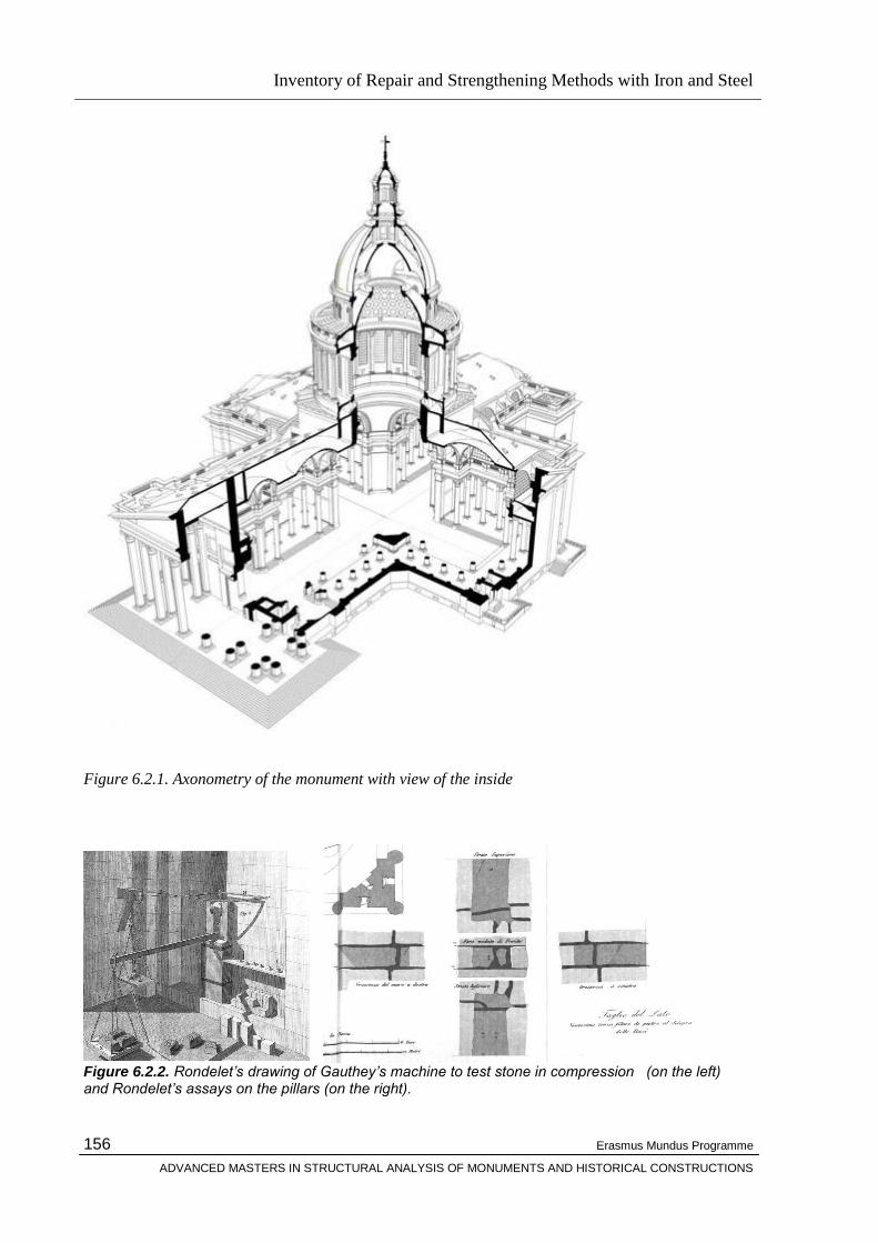
Inventory of Repair and Strengthening Methods with Iron and Steel
Erasmus Mundus Programme
ADVANCED MASTERS IN STRUCTURAL ANALYSIS OF MONUMENTS AND HISTORICAL CONSTRUCTIONS
156
Figure 6.2.1. Axonometry of the monument with view of the inside
Figure 6.2.2. Rondelet‟s drawing of Gauthey‟s machine to test stone in compression (on the left) and Rondelet‟s assays on the pillars (on the right).

Inventory of Repair and Strengthening Methods with Iron and Steel
Erasmus Mundus Programme
ADVANCED MASTERS IN STRUCTURAL ANALYSIS OF MONUMENTS AND HISTORICAL CONSTRUCTIONS
157
Figure 6.2.3. Schematic survey of the main crack systems (position and global interpretation) 6.2.2 The Causes of the Main Disorders
The reinforced stone masonry was a building technique completely new at the time of the construction
of the Panthéon. It was made possible by the spreading of iron due to the technological development
at the beginning of the industrial era. This new technique allowed Soufflot to realize very slender
structures, comparable only with the structures that one century later will be made with reinforced
concrete. Indeed, looking at the drawings depicting the iron clamps in the flat arches, it seems to look
at drawings of reinforced concrete trusses (Figure 6.2.4). Soufflot has developed his design basing
only upon his structural intuition and also the calculations made by his friends and co-workers
Gauthey and Rondelet are little compared to the complexity of the problems posed by the new
structures.

Inventory of Repair and Strengthening Methods with Iron and Steel
Erasmus Mundus Programme
ADVANCED MASTERS IN STRUCTURAL ANALYSIS OF MONUMENTS AND HISTORICAL CONSTRUCTIONS
158
Figure 6.2.4 The drawing depicting the iron clamps in the flat arches clearly recalls reinforced concrete trusses The slenderness of the structures, together with the real long time deformability of the masonry (2000
MPa) has, however, produced large deformations on structures, unpreviewed and non congruous with
the fragility of reinforced stone masonry. The presence of iron clamps, indeed, produces, under long
time loads, stress concentrations in the stone and consequent fractures. The characteristic shape of
the cracks in the stones due to the presence of the iron clamps was exactly recreated with numerical
crack models. In brief it was demonstrated as the cause of fractures, repeated in a perfectly symmetric
way in the whole building, is to be traced back in the global deformability of the masonry, associated
with the local fragility of connections . In particular, the structural elements that mainly show problems
and deformations are the four great arches, with a span of over 30 metres, that sustain the external
colonnade of the tambour. These arches thrust on the boundary walls both with high static horizontal
forces (about 3300 kN) and with dynamic actions caused by the wind.
6.2.3 Concluding Remarks
As it is clearly impossible to remove all the clamps between the stones without destroying the
monument, the solution to hinder new fractures must be searched in the introduction of pre-stressing
systems in masonry and, overall, in the active opposition to the thrust of the four great arches.
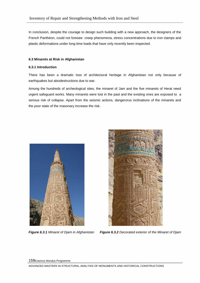
Inventory of Repair and Strengthening Methods with Iron and Steel
Erasmus Mundus Programme
ADVANCED MASTERS IN STRUCTURAL ANALYSIS OF MONUMENTS AND HISTORICAL CONSTRUCTIONS
159
In conclusion, despite the courage to design such building with a new approach, the designers of the
French Panthéon, could not foresee creep phenomena, stress concentrations due to iron clamps and
plastic deformations under long time loads that have only recently been inspected.
6.3 Minarets at Risk in Afghanistan
6.3.1 Introduction
There has been a dramatic loss of architectural heritage in Afghanistan not only because of
earthquakes but alsodestructions due to war.
Among the hundreds of archeological sites, the minaret of Jam and the five minarets of Herat need
urgent safeguard works. Many minarets were lost in the past and the existing ones are exposed to a
serious risk of collapse. Apart from the seismic actions, dangerorus inclinations of the minarets and
the poor state of the masonary increase the risk.
Figure 6.3.1 Minaret of Djam in Afghanistan Figure 6.3.2 Decorated exterior of the Minaret of Djam

Inventory of Repair and Strengthening Methods with Iron and Steel
Erasmus Mundus Programme
ADVANCED MASTERS IN STRUCTURAL ANALYSIS OF MONUMENTS AND HISTORICAL CONSTRUCTIONS
160
In 1961, architect Andrea Bruno began surveys and projects for the restoration of Afghan monuments
together with the Italian institute ISMEO which continued in 1976 and 1979 with surveys and
restorations of Jam and Herat for UNDP and UNESCO (Bruno 1981).
All the experts who had the opportunity to see it agree that the tower is on the verge of collapse. The
out of plumb is 2.70 m and a large horizontal crack is present at the height of 3 m from the base. The
structural analysis show that the eccentricity of the self weight is is such that the cross section is
cracked for one third of the diameter, and the edge of the masonry is subject to a a very high
compression, 1.2 Mpa. A moderate earthquake or a strong wind may cause the collapse of the
minarete, as already happened to the four other minarets which were still standing in 1915.
Figure 6.3.3 Minaret 5 (Musallah Complex)
6.3.2 Emergency Securing of the Minaret Five in Herat
Minaret 5 is made of brick, 42 m high with a diameter of 5m only at the base. The surface has a kashi
decoration with a geometrical pattern filled in with blue tiles.
Both the numerical assesment and the site measurements showed an extremely alarming situation.
As there was not enpough time for the implementation of the structural interventions approved by
UNESCO in 2003. i.e . stabilization of the foundation by menas of single bar micropiles and
strengthening of the elevation by means of a vertical prestress applied through high strenght steel
bars directly connected to the micropile bars. There fore emergency measureswere applied to the
minaret during July , August and September 2003.
The emergency securing was realized by means of simple steel stays anchored to concrete blocks
poured in the natural soil (out of any remains), thus avoiding the necessity of driving piles as fixed
points.The proposal was conceived in a way to use only the means available on site for the anchoring.
Steel cables were supplied from Italy together with the anchorages , hydraulic jacks and other
elements required for the operation.

Inventory of Repair and Strengthening Methods with Iron and Steel
Erasmus Mundus Programme
ADVANCED MASTERS IN STRUCTURAL ANALYSIS OF MONUMENTS AND HISTORICAL CONSTRUCTIONS
161
The concrete blocks, built by local workers, were embedded in the soil at a distance of 25 m from the
basis of the tower. The centers of the blocks were placed on two axes 15 degree far from the
maximum lena plane in order to secure the tower for an angle of 30 degree. In each block, 4 steel
pipes were embedded in the concrete in order to accomodate 4 stays and their anchorages.
Each stay was made of sinfle 0.6‖ strand of galvanized high tensile steel (area=150 mm2, strenght =
265 kN) . Each stay was applied along a precisely defined path (see figure 6.3.4 and the model of
Figure 6.3.5): Each starndstarts from a concrete block and reaches the tower surface with the
appropriate inclination, the is winded to it along a variable angle spiral until a sub-horizontal circle
allows to begin a descending path towards the other concrete block and its anchor. This arrangement
of the stays was essential in order to transfer to the tower the vertical component of the stabilizing
action through the steel –to masonry friction, therefore without slip and without heavy steel fastenings.
In this way the small force of 100 Kn only, applied by jacks to each of the four strands, has been
sufficient to close the base crack, to decrese the eccentricity of 0.65 m and therefore bring back the
masonry to state of total compression , the maximum stress was reduced to 0.6 Mpa.
The application of strand was performed in two weeks by a single tcehnician from Italy who was
supported by local workmanship.
The continous monitoring showed that the top of the tower moved back about 16 mm and therefore
showed the favorable effect. This quick, simple , efficient intervention show s how emergency works
may avoid the total loss of some precious monuments in a cheap way and without invasive structures.
6.3.3 Minaret of Jam
The minaret of Jam is far more important than the Herat minarets for its extraordinary size: 65 m. Of
height, close to that of Qutub Minar in New Delhi that was built in the same period at the end of the
12th century. The tallest minaret in the world isolated in the mountains in the Left Bank of the Hari Rud
River. The tower has a great architectural and historic value and is now the symbol of Afghanistan in
the World Heritage. It is very important monument for the Ghurid Dynasty.
The architecture is highly sofisticated. The tower is built with fired bricks, and is formed by three
cylindrical superposed shafts on an octagonal basis. The diameter of the base is 9 m only. Two
helicoidal internal stairways leading up one above the other , to a balcony at the top of the first tier at
the level of 40 m stand for the unusual features of the tower.
A first essential emergency intervention was implemented between 1975 and 1980 when A Bruna
installed metal gabionsprotecting the foundation from scouring. However, no further action was
possibleuntil 1999, when the protection was strengthened and new mission was took place in 2002.
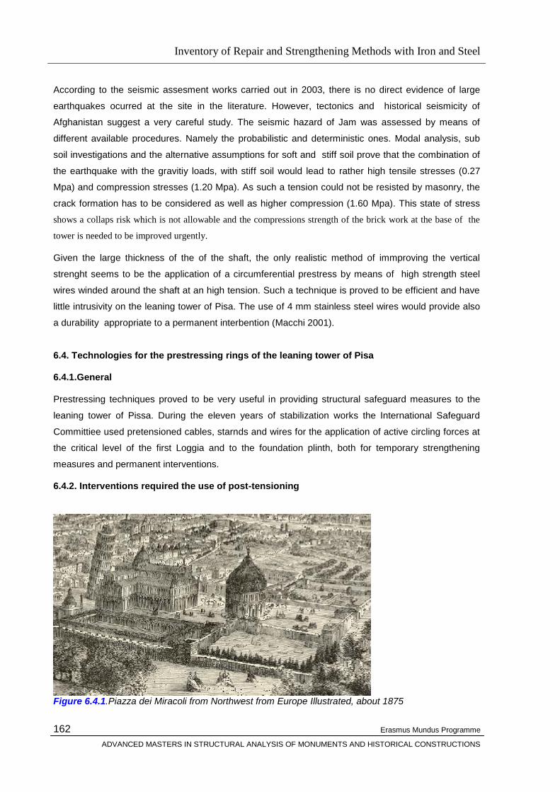
Inventory of Repair and Strengthening Methods with Iron and Steel
Erasmus Mundus Programme
ADVANCED MASTERS IN STRUCTURAL ANALYSIS OF MONUMENTS AND HISTORICAL CONSTRUCTIONS
162
According to the seismic assesment works carried out in 2003, there is no direct evidence of large
earthquakes ocurred at the site in the literature. However, tectonics and historical seismicity of
Afghanistan suggest a very careful study. The seismic hazard of Jam was assessed by means of
different available procedures. Namely the probabilistic and deterministic ones. Modal analysis, sub
soil investigations and the alternative assumptions for soft and stiff soil prove that the combination of
the earthquake with the gravitiy loads, with stiff soil would lead to rather high tensile stresses (0.27
Mpa) and compression stresses (1.20 Mpa). As such a tension could not be resisted by masonry, the
crack formation has to be considered as well as higher compression (1.60 Mpa). This state of stress
shows a collaps risk which is not allowable and the compressions strength of the brick work at the base of the
tower is needed to be improved urgently.
Given the large thickness of the of the shaft, the only realistic method of immproving the vertical
strenght seems to be the application of a circumferential prestress by means of high strength steel
wires winded around the shaft at an high tension. Such a technique is proved to be efficient and have
little intrusivity on the leaning tower of Pisa. The use of 4 mm stainless steel wires would provide also
a durability appropriate to a permanent interbention (Macchi 2001).
6.4. Technologies for the prestressing rings of the leaning tower of Pisa
6.4.1.General
Prestressing techniques proved to be very useful in providing structural safeguard measures to the
leaning tower of Pissa. During the eleven years of stabilization works the International Safeguard
Committiee used pretensioned cables, starnds and wires for the application of active circling forces at
the critical level of the first Loggia and to the foundation plinth, both for temporary strengthening
measures and permanent interventions.
6.4.2. Interventions required the use of post-tensioning
Figure 6.4.1.Piazza dei Miracoli from Northwest from Europe Illustrated, about 1875

Inventory of Repair and Strengthening Methods with Iron and Steel
Erasmus Mundus Programme
ADVANCED MASTERS IN STRUCTURAL ANALYSIS OF MONUMENTS AND HISTORICAL CONSTRUCTIONS
163
Among the temporary and permanent structural interventions, four of them required the use of post
tensioning which are described below:
The First temporary and reversible prestress was made in 1992 on the first Loggia zone and could be
defined as an urgent ―first aid‖ intervention aimed at preserving the life of the monument during
definition and realization of its final stabilization. The second temporary and reversible prestressing
work was made in 1993. A temporary ring of concrete segments pressed against the bottom of the
Tower surface by means of unbonded internal post-tenisoning tendons.
The beam was designed to support the lead ingots necessary to counterbalance the Tower
appropriately during the time necessary for the stabilizationd of the foundation of the tower.
The third work , realised in 2001, consisted in the replacement of the first temporary ring of 1992 with
permanent, but reversible, circumferential prestressing belts made of a stainless steel wire.
The fourth permanent intervention, made in 2001, is the permanent construction of a concrete ring
under the Catino surface that was blocked to the foundation by means of post-tensioned unbonded
internal tendons.
All the strengthening works, were carried out according to the specifications of the international
committee appointed by the Italian Government in 1990 and were performed with a proven reversible
prestressing technology that allows the gradual and monitored tensioning of the tendons, the control
and adjustment of their stress, the replacement of the tensile elements.
Furthermore, any deterioration or damage of the Tower surface had to be avoided.
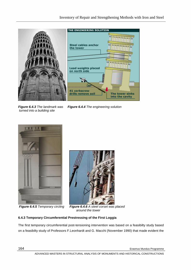
Inventory of Repair and Strengthening Methods with Iron and Steel
Erasmus Mundus Programme
ADVANCED MASTERS IN STRUCTURAL ANALYSIS OF MONUMENTS AND HISTORICAL CONSTRUCTIONS
164
Figure 6.4.3 The landmark was Figure 6.4.4 The engineering solution turned into a building site
Figure 6.4.5 Temporary circling Figure 6.4.6 A steel corset was placed around the tower 6.4.3 Temporary Circumferential Prestressing of the First Loggia
The first temporary circumferential post-tensioning intervention was based on a feasibilty study based
on a feasibilty study of Professors F.Leonhardt and G. Macchi (November 1990) that made evident the
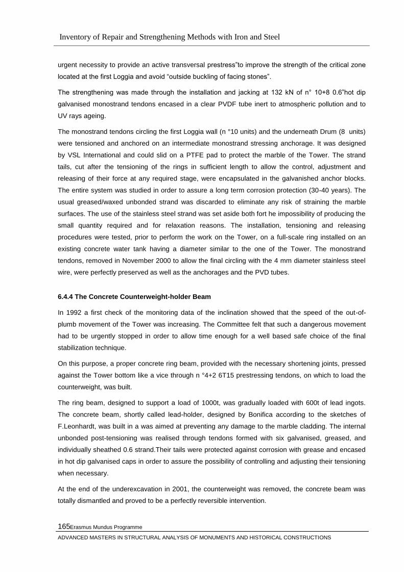
Inventory of Repair and Strengthening Methods with Iron and Steel
Erasmus Mundus Programme
ADVANCED MASTERS IN STRUCTURAL ANALYSIS OF MONUMENTS AND HISTORICAL CONSTRUCTIONS
165
urgent necessity to provide an active transversal prestress‖to improve the strength of the critical zone
located at the first Loggia and avoid ―outside buckling of facing stones‖.
The strengthening was made through the installation and jacking at 132 kN of n° 10+8 0.6‖hot dip
galvanised monostrand tendons encased in a clear PVDF tube inert to atmospheric pollution and to
UV rays ageing.
The monostrand tendons circling the first Loggia wall (n °10 units) and the underneath Drum (8 units)
were tensioned and anchored on an intermediate monostrand stressing anchorage. It was designed
by VSL International and could slid on a PTFE pad to protect the marble of the Tower. The strand
tails, cut after the tensioning of the rings in sufficient length to allow the control, adjustment and
releasing of their force at any required stage, were encapsulated in the galvanished anchor blocks.
The entire system was studied in order to assure a long term corrosion protection (30-40 years). The
usual greased/waxed unbonded strand was discarded to eliminate any risk of straining the marble
surfaces. The use of the stainless steel strand was set aside both fort he impossibility of producing the
small quantity required and for relaxation reasons. The installation, tensioning and releasing
procedures were tested, prior to perform the work on the Tower, on a full-scale ring installed on an
existing concrete water tank having a diameter similar to the one of the Tower. The monostrand
tendons, removed in November 2000 to allow the final circling with the 4 mm diameter stainless steel
wire, were perfectly preserved as well as the anchorages and the PVD tubes.
6.4.4 The Concrete Counterweight-holder Beam
In 1992 a first check of the monitoring data of the inclination showed that the speed of the out-of-
plumb movement of the Tower was increasing. The Committee felt that such a dangerous movement
had to be urgently stopped in order to allow time enough for a well based safe choice of the final
stabilization technique.
On this purpose, a proper concrete ring beam, provided with the necessary shortening joints, pressed
against the Tower bottom like a vice through n °4+2 6T15 prestressing tendons, on which to load the
counterweight, was built.
The ring beam, designed to support a load of 1000t, was gradually loaded with 600t of lead ingots.
The concrete beam, shortly called lead-holder, designed by Bonifica according to the sketches of
F.Leonhardt, was built in a was aimed at preventing any damage to the marble cladding. The internal
unbonded post-tensioning was realised through tendons formed with six galvanised, greased, and
individually sheathed 0.6 strand.Their tails were protected against corrosion with grease and encased
in hot dip galvanised caps in order to assure the possibility of controlling and adjusting their tensioning
when necessary.
At the end of the underexcavation in 2001, the counterweight was removed, the concrete beam was
totally dismantled and proved to be a perfectly reversible intervention.

Inventory of Repair and Strengthening Methods with Iron and Steel
Erasmus Mundus Programme
ADVANCED MASTERS IN STRUCTURAL ANALYSIS OF MONUMENTS AND HISTORICAL CONSTRUCTIONS
166
6.4.5 Circumferential Prestressing at the First Loggia with a 4mm Dia. Stainless Steel Wire
When the stabilization works (realised as known through the progressive and monitored extraction of
soil cored from the ground under the Nrthern sector of the Catino), were close to get the required
reduction of the Tower lean, The Committee decided to remove the temporary ringing strands installed
on the first Loggia zone and to proceed, at G. Macchi proposal, to the permanent but reversible
circling of that critical zone with narrow stainless steel wire made belts of the same capacity of the
previous strand rings. The change aimed at less visual impact and beter durability. The guideline
stated that the circumferential prestress had to be realised with a proven technology using stainless
steel resistent to the stmosphere corrosion, had to be applied gradually and controlled by monitoring,
should not damage the Tower surfaces pressed by the tensioned wires, should have a limited impact
on the Monument, had to be reversible and, during his installation should not damage the Tower
neither disturb the peculiar ambient noise coming from the tourist activities in the Piazza.
The technical design and the implementation of the prestressing rings was assigned, through the
Consorzio Progetto Torre di Pisa.
The guiding idea was to build a proper winding machine that could continuously lay a stainlesss steel
wire under the tension on the Tower surface using the available mechanical facilities and according to
the specific characteristics of the Monument. This could be made with the technology utilised along
several years in the past for the external post-tensioning of the cylindrical silos or tanks.
A cold drawn (4 mm dia) austenitic stainless steel wire (NTR 50, equivalent to ASTM A276 S20910),
with an excellent resistance to (its yield point is about the double of AISI 3161, stainless steel ), was
chosen for the circling.
The wire dimension, was defined according to the maximum stressing force supllied by the winding
machine (10 Kn) , to the mechanical characterisrics of the cold-drawn wire (resistance 1400 N/mm2
,
to the stressing tension (<700 N/mm2) applicable to the wire without inducing relaxation phenomena in
the stainless steel and according to the diameter of the tensioning device too.
In order to contain the maximum width of the stressing belt on the Drum in nomore than 145 mm and
to make the ornamental band of black marble that decorates the cornice completely visible, the wires
were winded spire against spire on four overlapped layers.of 34, 31, 28 and 25 spires respectively ,
that supplied a total prestressing force of approximately 910 Kn. The first three layers were painted
with a waxfilm to fill the capillary voids between the spires and to prevent crevice corrosion
phenomena.
Ech layer was anchored to the tower through independent stainless steel clamps while stainless steel
pins were properly installed to contrast the deviation points. The wire belt es secured to the tower with
five narrow equispaced stainless plates. The job was made during the first sixteen days of Jnuary
2001 under difficult weather conditions.

Inventory of Repair and Strengthening Methods with Iron and Steel
Erasmus Mundus Programme
ADVANCED MASTERS IN STRUCTURAL ANALYSIS OF MONUMENTS AND HISTORICAL CONSTRUCTIONS
167
The circling of Loggia base was realised, in a similar way but working in a very cramped space with a
belt of approximately 100 mm only formed by three layers of stainless steel wires (24+21+18 spires
respectively) that supply a total prestressing force of approximately 480 Kn. The marble surface of the
Tower was carefuly protected from the direct contact of the steel chain with a wooden belt warapped
by a rubber band.
6.4.6 The Catino Bottom Restorign and its Connection to the Tower
The first solution designed by the Commitee for the Tower stabilization could be summerized very
shortly in the construction of a concrete ring beam under the catino surface blocked to the Tower
foundation through internal bonded tendons. Ten deep ground anchors, of 1000 Kn capacity each
one, anchored on the North side to the ring beam allowed to apply a defined, adjustable and
monitored force to the Tower on its overslope side, to reduce and to control its lean. The project is
known as ― 10 anchors project‖ too.
When the first five segments of the foundation ring in the north edge of the tower were made, during
the gorunf freezing for the construction of the first segment on the South (underslope) side, the lean of
the Tower increased suddenly (September 1995). The prestressing force in the lead holder beam was
immediately increased, according to the design specifications, and the counterweight increased up to
900t. That unexpected and worrying behaviour, due to an unknown accidental connection between the
Catino and the Tower, caused the prompt stop of the works and successively the abonden of that
project.
In the year 2001, when the stabilizing operation according to the underexcavation method was ended,
the Committee decided to restore the bottom of the Catino and to connect it to the Tower foundation
through a concrete ring that includes the five segments already realised, pressed against the
foundation by means of post-tensioning internal replaceable unbonded tendons.
The intervention had not to remove the Catino foundations on the South side but ınly its upper layer
(140mm thick) that was already cracked, had to leave visible the half height of the first step at least,
had to provide the correct waterproofing and drainage of the water in the Catino area, had to utilise
only stainless reinforcing bars.
The design, developed by the Author in co-operation with G. Nicolini of ALGA group and the essential
contribution of G. Macchi, L. Sanpaolesi and R. Bartelletti, led to the realisation of a thin ring slab, 140
mm thick only, concreted on the South side of the Catino encasing n° 36 0.62‖ monostrand tendons
positioned on two layers.
The connection of the 36 monostrand tendons coming from the South side to the 4 upper 12T15S
tendons coming through the five concrete segments from the North side, was realised with two special
trapezoidal steel anchorages 390 mm thick only resisting the 6000 kN stated ringing force, on which
the tendons were anchored.

Inventory of Repair and Strengthening Methods with Iron and Steel
Erasmus Mundus Programme
ADVANCED MASTERS IN STRUCTURAL ANALYSIS OF MONUMENTS AND HISTORICAL CONSTRUCTIONS
168
The moderate vertical lifting force (120 kN) caused by the misalignment of the centrelines of the North
and South orders of tendons was balanced by the anchorages mass, by their friction against the
Tower foundation, by their connection to the Catino perimetral wall.
To assure the maximum possible anticorrosion protection, galvanised, waxed and sheathed 15,7 mm
super strand was used. The unbonded monostrand tendons were furthermore individually encased in
additional HDPE continuous tubes, sealed at their extremity to the steel anchorages, to allow their
replacemtn if necessary. The steel anchorages were protected from the corrosion with a thick
(1200mm) fiml of epoxy-polymminic paint that provides their electric insulation too. The ring slab and
the five concrete segments were properly anchored to the Catino and Tower foundations with
stainless steel bars. The stressing operation was performed through equilibrated, symmetrical and
incremental steps according to a detailed stressing program involving the constant Monument
monitoring. Jacks and deviators designed on purpose were used to operate in the small available
anchorages space.
After a convenient control period, the steel anchorages were inspected and filled , with a proper anti-
corrosion, hydrophobic , insoluble and climatic variation resistant wax, in order to impede any water
infiltration.
The realisation does not preclude the possibility to install and connect ten deep ground anchors to the
five concrete sectors on the North side, if necessary.
6.4.7 Concluding Remarks
The described realisations show how a prestressing technique, conceived fort the post-tensioning of
industrial buildings or structures, can be utilised fort he strengthening of Monuments of high
architectural and historical value, if properly developed in details and suited to that particular use.
6.5 Use of Shock Transmission Units and Shape Memory Ally Devices for the Seismic
Protection of Monuments: The case of the Upper Basilica of San Francesco at Assisi
6.5.1 General
A traditional technique to increase the strength of masonry walls and/or improve the connection
between different structural elements, thus improving the local and global seismic behaviour, is the
use of reinforced injections. But in many monumental structures, the presence of frescoes and/or the
limited thickness of the walls, as well as the willingness to limit as much as possible not reversible
interventions, does not allow use of such techniques. In these cases, additional stiffening elements are
introduced, such as steel beams. This solution, however, is not without problems as it may hinder the
natural breathing of very wide historical buildings, that is relative movements due to thermal effects,
seasonal water table variations, etc.. In some cases, especially when the building dimensions are very
Inventory of Repair and Strengthening Methods with Iron and Steel
Erasmus Mundus Programme
ADVANCED MASTERS IN STRUCTURAL ANALYSIS OF MONUMENTS AND HISTORICAL CONSTRUCTIONS
169
large, it may be useful to divide the global connections in sub-elements connected by ―shock
transmission units‖ (STUs), i.e. elements which allow slow relative movements but prevent any
instantaneous ones. At the same time, the traditional technique to improve the seismic resistance of a
building guaranteeing its box behaviour, creating connections between horizontal stiff frames (roofs
and floors) and peripheral walls, generally allows no important and useful energy dissipation, and can
induce very high forces on the masonry elements. The linking technique may be improved using an
innovative material called ―shape memory alloy‖ (SMA) in specifically designed connection devices.
Several advantages may be accrued by these devices in comparison to traditional steel ties, concrete
beams, etc.. Particularly, by using these devices it is possible to allow ―controlled‖ relative
displacements, limiting the forces and the acceleration transmitted, and inducing energy dissipation by
the masonry itself. A significant example of the application of these intervention criteria may be found
in the Basilica of San Francesco at Assisi, restored after being strongly damaged by the earthquake of
1997.
6.5.2. Device Properties
Shock transmission units (STUs) are structural devices, used to connect structural elements, whose
behaviour depends on the velocity of the relative movement between said elements. In effect, they
allow low velocity movements, such as those due to thermal variations or other slow phenomena
reacting with very low forces. Conversely, under high velocity excitations (e.g. earthquakes, strong
winds, etc.), they are very stiff, preventing the structural elements they connect from significant relative
movements, and transmitting them the design force. Thus, shock transmission units act as temporary
restraints. Since many years they have been used in new structures, mainly in bridges and viaducts to
connect deck to piers or abutments, as well as in buildings. However, their behaviour is also useful for
the seismic protection of historical and monumental structures, to provide the stiffness needed to
withstand the earthquake without inducing undesired forces under service conditions. The use of
STUs in historical structures have been first proposed and applied in Italy about 10 years ago, for the
dynamic connection of a new steel roof structure to the masonry walls of a church [1]. STUs are
devices comprising a cylinder-piston system with two chambers filled with a special fluid and
connected through an hydraulic circuit. When they are used in historical structures, a special care
should be taken in the selection of materials . The connections of the devices should be designed to
allow an easy replacement, respecting the criterion of reversibility of interventions. SMAs are metals
endowed with very unusual thermo -mechanical properties, comprising the superelastic behaviour,
that is, the ability to recover from large deformations (greater than 10 times that of conventional
metals) during loading-unloading cycles. In the loading phase, the stress-strain curve shows a
"plateau" (i.e.: a section where stress remains nearly constant with increasing strain), similar with the
one seen by yielding but instead due to the stress-induced reversible and non damaging phase
transformation from Austenite to Martensite. Loading and unloading paths generate an hysteresis loop
and thus energy dissipation. The SMA superelastic behaviour makes them particularly suitable to

Inventory of Repair and Strengthening Methods with Iron and Steel
Erasmus Mundus Programme
ADVANCED MASTERS IN STRUCTURAL ANALYSIS OF MONUMENTS AND HISTORICAL CONSTRUCTIONS
170
create force limiting devices. SMA Devices (SMADs) have been developed to overcome some
drawbacks of traditional very stiff steel ties, used to connect masonry walls with floors and/or roof and
thus reduce the risk of out-of-plane collapse of peripheral walls. In effect, SMADs work as far more
flexible ties, capable of allowing controlled displacements, and limiting forces under a pre-established
value [15]. The SMADs use SMAs in the form of wires, suitably connected to work always under
tension and giving the device a symmetric behaviour regardless of the direction of the displacement.
They are designed to have different response for different intensity of external action:
a) For low horizontal action (wind, small intensity earthquakes) the device is stiff, as a traditional steel
connection, and no significant displacements are allowed.
b) For higher horizontal actions the stiffness of the device reduces thanks to the ―superelastic plateau‖,
and ―controlled displacements‖ are allowed. The latter should allow the masonry to dissipate part of
the energy transmitted by the earthquake mainly thanks to micro-cracks in the masonry structure,
taking care to avoid dangerous macro cracks. Furthermore, SMADs transmit to the structure smaller
forces than steel ties do.
c) For extraordinary horizontal actions (i.e. higher than the design earthquake) the stiffness of the
device grows up in order to prevent from excessive displacements and instability. Shaking table
experimental tests carried out on mock-ups of masonry façade walls connected to the structure by
different devices showed that there is significant improvement in seismic response by using SMA
devices instead of steel bars to tie walls. Not only is the out-of-plane collapse of the wall partly below
the tying level prevented but that of the wall partly above it (representing the tympanum of a church
façade) as well [16]. The SMA with the best performance is NiTi, an alloy that also has very high
resistance to corrosion. High durability of SMADs is obtained using NiTi wires and stainless steel.
Figure 6.5.1 The horizontal stainless steel beam all along the Upper Basilica

Inventory of Repair and Strengthening Methods with Iron and Steel
Erasmus Mundus Programme
ADVANCED MASTERS IN STRUCTURAL ANALYSIS OF MONUMENTS AND HISTORICAL CONSTRUCTIONS
171
Shaking table experimental tests carried out on mock-ups of masonry façade walls connected to the
structure by different devices showed that there is significant improvement in seismic response by
using SMA devices instead of steel bars to tie walls. Not only is the out-of-plane collapse of the wall
partly below the tying level prevented but that of the wall partly above it (representing the tympanum of
a church façade) as well [16]. The SMA with the best performance is NiTi, an alloy that also has very
high resistance to corrosion. High durability of SMADs is obtained using NiTi wires and stainless steel.
6.5. 3 The Case of the Upper Basilica of San Francesco at Assisi
6.5.3.1 General Description
In its history many earthquakes have hit the Basilica of St Francis (Figure 26), which was built in the
13th century. Important earthquakes occurred in 1279, 1328, 1703, 1747, 1781, 1799, 1832, 1859,
1917, 1979, and yet none produced damage as great as that which hit central Italy during the night of
September 26, 1997, as well as the second that struck the Basilica at 11,42 a.m. The result was the
destruction of the vaults close to the façade, of
those close to the transept, of a portion of the left transept (Figure 27) and the production of large
cracks and permanent deformation all over the vaults of the Basilica, leaving them in a very precarious
and dangerous condition. Besides the differing impact that earthquakes of different characteristics,
which followed each other during the centuries, may have produced on the Basilica, other factors have
increased the vulnerability with respect to the past.
One factor is certainly the presence of a large volume of fill which was mainly broken tiles and other
loose materials accumulated over centuries of roof repairs in the springer zones. During seismic
activity, this fill, without any cohesion, alternatively acts only on one side, whilst on the other side the
fill is detached. Furthermore the lose fill follows the movement of the vaults, opposing their recovery
and facilitating increasing permanent deformations. When the quake of September 26 hit the Basilica,
it is very likely that permanent deformation, reducing the curvature and therefore the bearing capacity,
was already present, having been progressively produced and increased during the previous
earthquakes (and this is another important factor).

Inventory of Repair and Strengthening Methods with Iron and Steel
Erasmus Mundus Programme
ADVANCED MASTERS IN STRUCTURAL ANALYSIS OF MONUMENTS AND HISTORICAL CONSTRUCTIONS
172
Figure 6.5.2 The Basilica of St. Francesco of Assisi The restoration project of St. Francis Basilica in Assisi has been made by Prof. Eng. G. Croci and Prof.
Arch. P. Rocchi, with the participation of Eng. G. Carluccio and Eng. A. Viskovic, under the
supervision of Dr. A. Paolucci, the artistic co-ordinator of the Ministry of Cultural Heritage, Arch. C.
Centroni, Superintendent of Umbria.. The on site installation of the STUs and the SMADs was carried
out by FIP Industriale S.p.A.. under the supervision of Engg. M.G. Castellano, G. Carluccio and A.
Viskovic; the mathematical models and the analyses of these interventions have been done by Engg.
A. Bonci and A. Viskovic. The experimental laboratory tests were carried out by FIP Industriale (test on
SMADs) and by ENEA (shaking table tests on mock-ups with SMADs) under the supervision of Engg.
M. Indirli, M.G. Castellano, A. Bonci and A. Viskovic, within the ―ISTECH‖ Research Project partially
funded by the European Commission (Contract No. ENV4-CT95-0106, 4th Framework Programme) .
The St. Francis Basilica is built up by two distinct Basilicas, the Upper and the Lower, one on the top
of the other. Vertical cracks are located near the centre of each bay of the side walls of the Upper
Basilica. Those cracks, opened and enlarged many times by past earthquakes, were reopened by the
last seismic event of 26 September 1997. Each crack starts from pavement level up to the level of
thetall window base, often cracking the window cornice itself, and is visible both on the internaland on
the external side. Considering that the top of the windows arrive near the roof level and, at the same
time, in each bay of the Lower Basilica there is a large and tall opening for the access to the lateral
chapels, the nave structure of the Basilica as a whole, results divided into vertical portions weakly
connected each other in the middle of each bay. The cracked side walls under the windows level in
the Upper Basilica are those with the presence of the Giotto‘s frescos. Thus a protection is required to
avoid excessive crack openings during seismic actions normal to the walls themselves, but the use of
reinforcement injections is excluded. Therefore a ―dry‖ and almost completely reversible intervention
consisting of a chain of steel trussed beams placed over the internal cornice, which is located at an
intermediate height just over the Giotto‘s frescos and under the windows, was adopted. Each beam
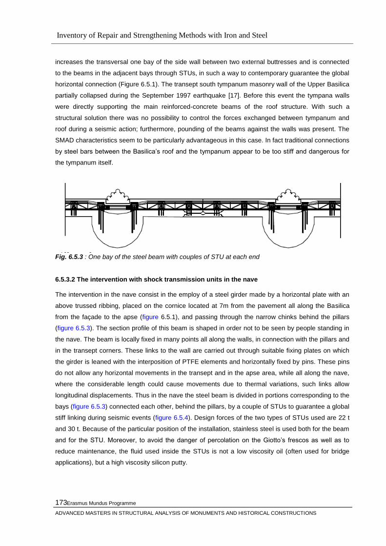
Inventory of Repair and Strengthening Methods with Iron and Steel
Erasmus Mundus Programme
ADVANCED MASTERS IN STRUCTURAL ANALYSIS OF MONUMENTS AND HISTORICAL CONSTRUCTIONS
173
increases the transversal one bay of the side wall between two external buttresses and is connected
to the beams in the adjacent bays through STUs, in such a way to contemporary guarantee the global
horizontal connection (Figure 6.5.1). The transept south tympanum masonry wall of the Upper Basilica
partially collapsed during the September 1997 earthquake [17]. Before this event the tympana walls
were directly supporting the main reinforced-concrete beams of the roof structure. With such a
structural solution there was no possibility to control the forces exchanged between tympanum and
roof during a seismic action; furthermore, pounding of the beams against the walls was present. The
SMAD characteristics seem to be particularly advantageous in this case. In fact traditional connections
by steel bars between the Basilica‘s roof and the tympanum appear to be too stiff and dangerous for
the tympanum itself.
Fig. 6.5.3 : One bay of the steel beam with couples of STU at each end
6.5.3.2 The intervention with shock transmission units in the nave
The intervention in the nave consist in the employ of a steel girder made by a horizontal plate with an
above trussed ribbing, placed on the cornice located at 7m from the pavement all along the Basilica
from the façade to the apse (figure 6.5.1), and passing through the narrow chinks behind the pillars
(figure 6.5.3). The section profile of this beam is shaped in order not to be seen by people standing in
the nave. The beam is locally fixed in many points all along the walls, in connection with the pillars and
in the transept corners. These links to the wall are carried out through suitable fixing plates on which
the girder is leaned with the interposition of PTFE elements and horizontally fixed by pins. These pins
do not allow any horizontal movements in the transept and in the apse area, while all along the nave,
where the considerable length could cause movements due to thermal variations, such links allow
longitudinal displacements. Thus in the nave the steel beam is divided in portions corresponding to the
bays (figure 6.5.3) connected each other, behind the pillars, by a couple of STUs to guarantee a global
stiff linking during seismic events (figure 6.5.4). Design forces of the two types of STUs used are 22 t
and 30 t. Because of the particular position of the installation, stainless steel is used both for the beam
and for the STU. Moreover, to avoid the danger of percolation on the Giotto‘s frescos as well as to
reduce maintenance, the fluid used inside the STUs is not a low viscosity oil (often used for bridge
applications), but a high viscosity silicon putty.
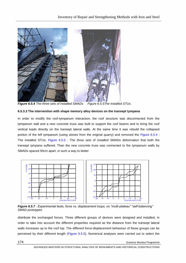
Inventory of Repair and Strengthening Methods with Iron and Steel
Erasmus Mundus Programme
ADVANCED MASTERS IN STRUCTURAL ANALYSIS OF MONUMENTS AND HISTORICAL CONSTRUCTIONS
174
Figure 6.5.4 The three sets of installed SMADs Figure 6.5.5The installed STUs.
6.5.3.3 The intervention with shape memory alloy devices on the transept tympana
In order to modify the roof-tympanum interaction, the roof structure was disconnected from the
tympanum wall and a new concrete truss was built to support the roof beams and to bring the roof
vertical loads directly on the transept lateral walls. At the same time it was rebuild the collapsed
portion of the left tympanum (using stones from the original quarry) and removed the Figure 6.5.4 :
The installed STUs. Figure 6.5.5 : The three sets of installed SMADs deformation that both the
transept tympana suffered. Than the new concrete truss was connected to the tympanum walls by
SMADs spaced 50cm apart, in such a way to better
Figure 6.5.7 : Experimental tests, force vs. displacement loops, on “multi-plateau” “self-balancing” SMAD prototypes
distribute the exchanged forces. Three different groups of devices were designed and installed, in
order to take into account the different properties required as the distance from the transept lateral
walls increases up to the roof top. The different force-displacement behaviour of these groups can be
perceived by their different length (Figure 6.5.5). Numerical analyses were carried out to select the
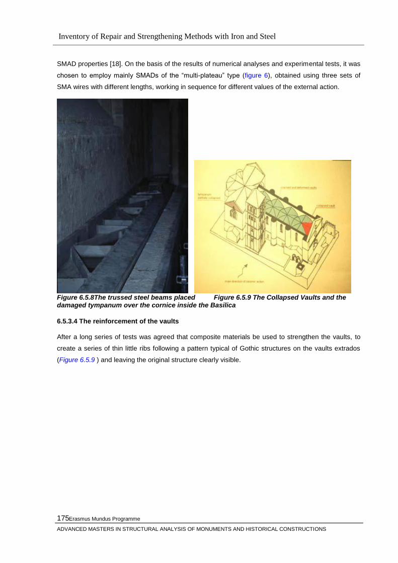
Inventory of Repair and Strengthening Methods with Iron and Steel
Erasmus Mundus Programme
ADVANCED MASTERS IN STRUCTURAL ANALYSIS OF MONUMENTS AND HISTORICAL CONSTRUCTIONS
175
SMAD properties [18]. On the basis of the results of numerical analyses and experimental tests, it was
chosen to employ mainly SMADs of the ―multi-plateau‖ type (figure 6), obtained using three sets of
SMA wires with different lengths, working in sequence for different values of the external action.
Figure 6.5.8The trussed steel beams placed Figure 6.5.9 The Collapsed Vaults and the damaged tympanum over the cornice inside the Basilica
6.5.3.4 The reinforcement of the vaults
After a long series of tests was agreed that composite materials be used to strengthen the vaults, to
create a series of thin little ribs following a pattern typical of Gothic structures on the vaults extrados
(Figure 6.5.9 ) and leaving the original structure clearly visible.

Inventory of Repair and Strengthening Methods with Iron and Steel
Erasmus Mundus Programme
ADVANCED MASTERS IN STRUCTURAL ANALYSIS OF MONUMENTS AND HISTORICAL CONSTRUCTIONS
176
Figure 6.5.9 The pattern followed by the new ribs placed on the extrados of the damaged vaults
These ribs are built in situ, so that it is possible to follow the deformed shape of the vaults; whilst the
width of the ribs remains constant, the height may then change in relation to the deformation of the
vaults Figure 6.5.10).
The ribs are made of aramid fibres bedded in epoxy resins around a central timber nucleus. These
fibres are light, very strong (the tensile strength of this fibre is 30.000 Kg/cm2 and that of the fibre with
resin is about 14.000 Kg/cm2) and less stiff than steel, the elasticity modulus of the fibre being
1.200.000 Kg/cm2 and that of the fibres with resin 600.000 Kg/cm2.
Figure 6.5.10 The ribs covered with aramidic fiber tissue Figure 6.5.11 The tie bars and springs

Inventory of Repair and Strengthening Methods with Iron and Steel
Erasmus Mundus Programme
ADVANCED MASTERS IN STRUCTURAL ANALYSIS OF MONUMENTS AND HISTORICAL CONSTRUCTIONS
177
which connect the ribs to the roof
The ribs are connected to a system of tie bars, which are anchored to the roof. Each tie bar includes a
spring, similar to the solution adopted for urgent measures (Figure 6.5.11). This reinforcement aims to
reduce the deformability under seismic forces. The reinforcement of the vaults‘ cracked structure, has
been completed by injections using a mortar salt-free and compatible with the frescoes, sufficiently
fluid to penetrate and diffuse to all the cracks and microcracks, capable of being injected in dry
masonry (no use of water is allowed) and having good strength and bond capacity so that a structural
continuity through the cracks may be established.
6.6 Strengthening of San Lorenzo Cathedral with Post-Tensioning, Perugia, Italy
The San Lorenzo Cathedral was built between the 14th and 15th centuries. Important consolidation
works carried out between 1633-1641 ,since, because of the weight of the roof, the columns adn the
walls had diverged. Seismic movements in 1983 caused further damage which endangered the
stability of the monument. A new consolidation and restoration project was decided after a thorough
historical survey of the original and the lower tie beam and the central king post with two twin 0 36 mm
Dywidag bars each. The column capitals showed displacements of up tp 26 cm. A new system of
transverse and longitudinal ties made of Dywidag bars was introduced into the columns and walls to
prevent any side displacements. The transverse tie members were prestressed and tied back to the
lateral walls in order to apply to the whole structure a system of acting forces capable of counter acting
the thrusts of the vaults.
6.7. Strengthening of GPO Tower with Post-Tensioning, Sydney
The general Post Office in Sydney, a more than one hundred year old sandstone masonry building,
was undergone a massive restoration both inside and outside. As part of this restoration, the GPO
Tower will be strengthened with four vertical post-tensioning tendons, 19 diameter 0.5" strands each,
and a number of horizontal prestressing bars diameter 35mm at floor levels ( Figure 6.7.1). The
vertical tendons will be placed in holes diameter 100mm drilled from the top through the sandstone
columns at the corner of the tower. Special steel chairs will be used to anchor the tendons and spread
the anchorage forces of 1,771 kN (400 kips). The anchorages of the unbonded tendons allow for
monitoring and adjustment of the tendon forces to compensate volume changes of the sandstone, if
necessary. The entire restoration was expected to take five years and installation and stressing of the
tendons was scheduled for 1990.

Inventory of Repair and Strengthening Methods with Iron and Steel
Erasmus Mundus Programme
ADVANCED MASTERS IN STRUCTURAL ANALYSIS OF MONUMENTS AND HISTORICAL CONSTRUCTIONS
178
Figure. 6.7.1: Strengthening of GPO Tower, Sydney General Post Office Building.
Figure 6.7.2 Tendon layout in tower, courtesy of McBean & Crisp, Pty, Ltd.
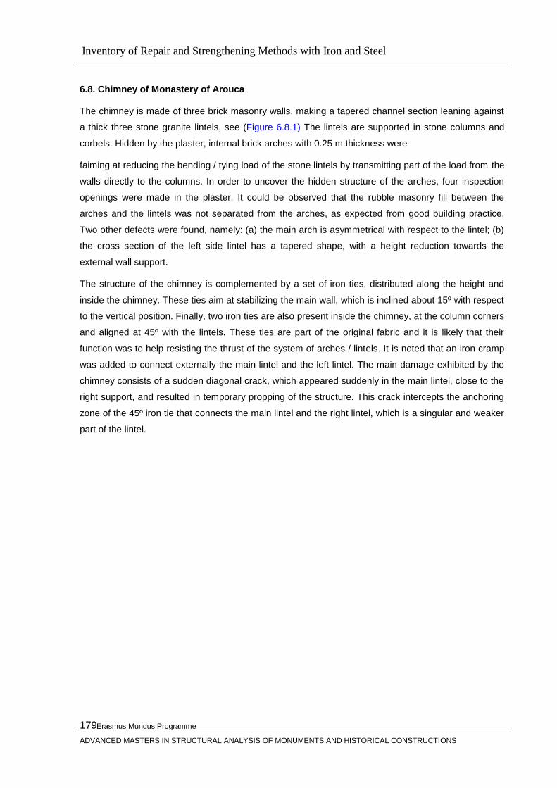
Inventory of Repair and Strengthening Methods with Iron and Steel
Erasmus Mundus Programme
ADVANCED MASTERS IN STRUCTURAL ANALYSIS OF MONUMENTS AND HISTORICAL CONSTRUCTIONS
179
6.8. Chimney of Monastery of Arouca
The chimney is made of three brick masonry walls, making a tapered channel section leaning against
a thick three stone granite lintels, see (Figure 6.8.1) The lintels are supported in stone columns and
corbels. Hidden by the plaster, internal brick arches with 0.25 m thickness were
faiming at reducing the bending / tying load of the stone lintels by transmitting part of the load from the
walls directly to the columns. In order to uncover the hidden structure of the arches, four inspection
openings were made in the plaster. It could be observed that the rubble masonry fill between the
arches and the lintels was not separated from the arches, as expected from good building practice.
Two other defects were found, namely: (a) the main arch is asymmetrical with respect to the lintel; (b)
the cross section of the left side lintel has a tapered shape, with a height reduction towards the
external wall support.
The structure of the chimney is complemented by a set of iron ties, distributed along the height and
inside the chimney. These ties aim at stabilizing the main wall, which is inclined about 15º with respect
to the vertical position. Finally, two iron ties are also present inside the chimney, at the column corners
and aligned at 45º with the lintels. These ties are part of the original fabric and it is likely that their
function was to help resisting the thrust of the system of arches / lintels. It is noted that an iron cramp
was added to connect externally the main lintel and the left lintel. The main damage exhibited by the
chimney consists of a sudden diagonal crack, which appeared suddenly in the main lintel, close to the
right support, and resulted in temporary propping of the structure. This crack intercepts the anchoring
zone of the 45º iron tie that connects the main lintel and the right lintel, which is a singular and weaker
part of the lintel.
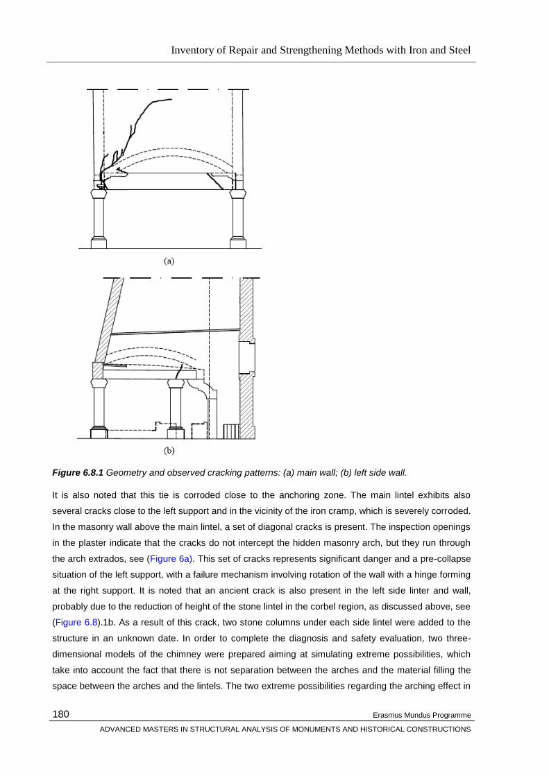
Inventory of Repair and Strengthening Methods with Iron and Steel
Erasmus Mundus Programme
ADVANCED MASTERS IN STRUCTURAL ANALYSIS OF MONUMENTS AND HISTORICAL CONSTRUCTIONS
180
Figure 6.8.1 Geometry and observed cracking patterns: (a) main wall; (b) left side wall.
It is also noted that this tie is corroded close to the anchoring zone. The main lintel exhibits also
several cracks close to the left support and in the vicinity of the iron cramp, which is severely corroded.
In the masonry wall above the main lintel, a set of diagonal cracks is present. The inspection openings
in the plaster indicate that the cracks do not intercept the hidden masonry arch, but they run through
the arch extrados, see (Figure 6a). This set of cracks represents significant danger and a pre-collapse
situation of the left support, with a failure mechanism involving rotation of the wall with a hinge forming
at the right support. It is noted that an ancient crack is also present in the left side linter and wall,
probably due to the reduction of height of the stone lintel in the corbel region, as discussed above, see
(Figure 6.8).1b. As a result of this crack, two stone columns under each side lintel were added to the
structure in an unknown date. In order to complete the diagnosis and safety evaluation, two three-
dimensional models of the chimney were prepared aiming at simulating extreme possibilities, which
take into account the fact that there is not separation between the arches and the material filling the
space between the arches and the lintels. The two extreme possibilities regarding the arching effect in

Inventory of Repair and Strengthening Methods with Iron and Steel
Erasmus Mundus Programme
ADVANCED MASTERS IN STRUCTURAL ANALYSIS OF MONUMENTS AND HISTORICAL CONSTRUCTIONS
181
the walls are considered here. Therefore, the first model does not include the filling material under the
arches (Model 1) and the second model considers that the walls are fully supported in the lintels
(Model 2). Obviously, Model 2 is more unfavorable for the stone lintels, being the most conservative
approach. The models are made of quadratic solid finite elements (bricks and wedges), with
approximately 500 elements and 3805 nodes, making a total of 11415 degrees of freedom. Non-linear
material properties have been considered both in tension and compression. Two loads have been
considered in the analysis, one due to the self-weight of the chimney and another due to the load The
linear elastic results of Model 1 and Model 2 indicated that the model without the internal arching
system leads to the most unfavorable loading conditions, as expected. Therefore, this model has been
selected for performing a non-linear analysis up to the collapse of the structure. Structural collapse
was found for a load factor of 2.04, where the load factor represents the ratio between the applied
loads and the original reference loads. For the ultimate load factor, the most damaged zones in the
masonry walls occur close to the supports of the side lintels, see Figure 6.8.2a. This damage is both in
tension and compression. Figure 6.8.2. b illustrates the damage (measured by the maximum principal
strains) for the lintels-columns set, which clearly defines the collapse mechanism. Three plastic hinges
appeared in the side lintels, one hinge at midspan with cracking at the lower face of the lintels (positive
bending moments), and two hinges at the supports with cracking at the upper face of the lintels
(negative bending moments).
Figure 6.8.2 . Principal strains plotted in the deformed mesh configuration for Model 2, using non-linear analysis and a load factor of 2.0: (a) brick masonry part of the model; (b) stone columns and lintels. The maximum (tension) strains are plotted in the left and the minimum (compression) strains are plotted in the right. Results are dimensionless and darker color indicates higher damage.
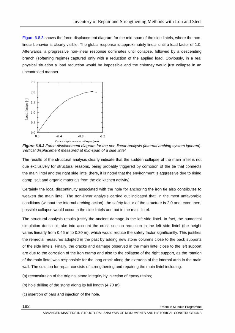
Inventory of Repair and Strengthening Methods with Iron and Steel
Erasmus Mundus Programme
ADVANCED MASTERS IN STRUCTURAL ANALYSIS OF MONUMENTS AND HISTORICAL CONSTRUCTIONS
182
Figure 6.8.3 shows the force-displacement diagram for the mid-span of the side lintels, where the non-
linear behavior is clearly visible. The global response is approximately linear until a load factor of 1.0.
Afterwards, a progressive non-linear response dominates until collapse, followed by a descending
branch (softening regime) captured only with a reduction of the applied load. Obviously, in a real
physical situation a load reduction would be impossible and the chimney would just collapse in an
uncontrolled manner.
Figure 6.8.3 Force-displacement diagram for the non-linear analysis (internal arching system ignored). Vertical displacement measured at mid-span of a side lintel.
The results of the structural analysis clearly indicate that the sudden collapse of the main lintel is not
due exclusively for structural reasons, being probably triggered by corrosion of the tie that connects
the main lintel and the right side lintel (here, it is noted that the environment is aggressive due to rising
damp, salt and organic materials from the old kitchen activity).
Certainly the local discontinuity associated with the hole for anchoring the iron tie also contributes to
weaken the main lintel. The non-linear analysis carried out indicated that, in the most unfavorable
conditions (without the internal arching action), the safety factor of the structure is 2.0 and, even then,
possible collapse would occur in the side lintels and not in the main lintel.
The structural analysis results justify the ancient damage in the left side lintel. In fact, the numerical
simulation does not take into account the cross section reduction in the left side lintel (the height
varies linearly from 0.46 m to 0.30 m), which would reduce the safety factor significantly. This justifies
the remedial measures adopted in the past by adding new stone columns close to the back supports
of the side lintels. Finally, the cracks and damage observed in the main lintel close to the left support
are due to the corrosion of the iron cramp and also to the collapse of the right support, as the rotation
of the main lintel was responsible for the long crack along the extrados of the internal arch in the main
wall. The solution for repair consists of strengthening and repairing the main lintel including:
(a) reconstitution of the original stone integrity by injection of epoxy resins;
(b) hole drilling of the stone along its full length (4.70 m);
(c) insertion of bars and injection of the hole.
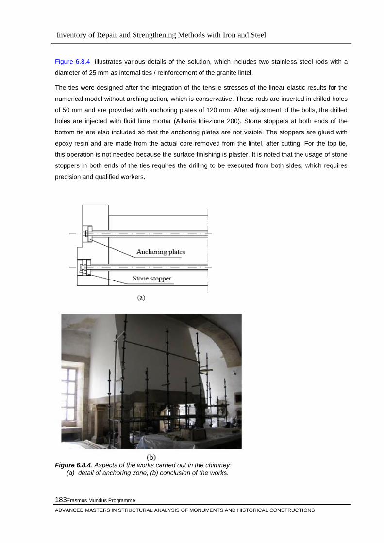
Inventory of Repair and Strengthening Methods with Iron and Steel
Erasmus Mundus Programme
ADVANCED MASTERS IN STRUCTURAL ANALYSIS OF MONUMENTS AND HISTORICAL CONSTRUCTIONS
183
Figure 6.8.4 illustrates various details of the solution, which includes two stainless steel rods with a
diameter of 25 mm as internal ties / reinforcement of the granite lintel.
The ties were designed after the integration of the tensile stresses of the linear elastic results for the
numerical model without arching action, which is conservative. These rods are inserted in drilled holes
of 50 mm and are provided with anchoring plates of 120 mm. After adjustment of the bolts, the drilled
holes are injected with fluid lime mortar (Albaria Iniezione 200). Stone stoppers at both ends of the
bottom tie are also included so that the anchoring plates are not visible. The stoppers are glued with
epoxy resin and are made from the actual core removed from the lintel, after cutting. For the top tie,
this operation is not needed because the surface finishing is plaster. It is noted that the usage of stone
stoppers in both ends of the ties requires the drilling to be executed from both sides, which requires
precision and qualified workers.
Figure 6.8.4. Aspects of the works carried out in the chimney:
(a) detail of anchoring zone; (b) conclusion of the works.
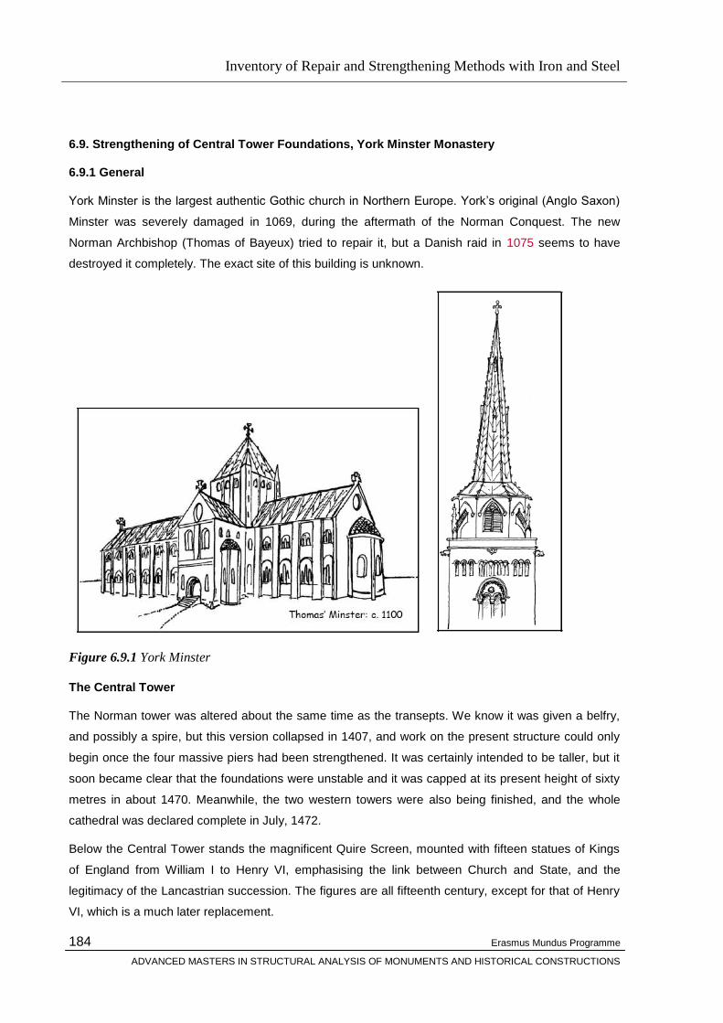
Inventory of Repair and Strengthening Methods with Iron and Steel
Erasmus Mundus Programme
ADVANCED MASTERS IN STRUCTURAL ANALYSIS OF MONUMENTS AND HISTORICAL CONSTRUCTIONS
184
6.9. Strengthening of Central Tower Foundations, York Minster Monastery
6.9.1 General
York Minster is the largest authentic Gothic church in Northern Europe. York‘s original (Anglo Saxon)
Minster was severely damaged in 1069, during the aftermath of the Norman Conquest. The new
Norman Archbishop (Thomas of Bayeux) tried to repair it, but a Danish raid in 1075 seems to have
destroyed it completely. The exact site of this building is unknown.
Figure 6.9.1 York Minster
The Central Tower
The Norman tower was altered about the same time as the transepts. We know it was given a belfry,
and possibly a spire, but this version collapsed in 1407, and work on the present structure could only
begin once the four massive piers had been strengthened. It was certainly intended to be taller, but it
soon became clear that the foundations were unstable and it was capped at its present height of sixty
metres in about 1470. Meanwhile, the two western towers were also being finished, and the whole
cathedral was declared complete in July, 1472.
Below the Central Tower stands the magnificent Quire Screen, mounted with fifteen statues of Kings
of England from William I to Henry VI, emphasising the link between Church and State, and the
legitimacy of the Lancastrian succession. The figures are all fifteenth century, except for that of Henry
VI, which is a much later replacement.
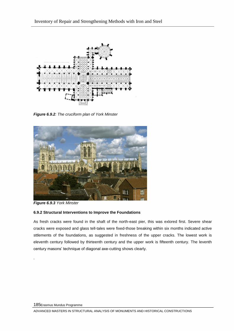
Inventory of Repair and Strengthening Methods with Iron and Steel
Erasmus Mundus Programme
ADVANCED MASTERS IN STRUCTURAL ANALYSIS OF MONUMENTS AND HISTORICAL CONSTRUCTIONS
185
Figure 6.9.2: The cruciform plan of York Minster
Figure 6.9.3 York Minster
6.9.2 Structural Interventions to Improve the Foundations
As fresh cracks were found in the shaft of the north-east pier, this was exlored first. Severe shear
cracks were exposed and glass tell-tales were fixed-those breaking within six months indicated active
sttlements of the foundations, as suggested in freshness of the upper cracks. The lowest work is
eleventh century followed by thirteenth century and the upper work is fifteenth century. The leventh
century masons‘ technique of diagonal axe-cutting shows clearly.
.
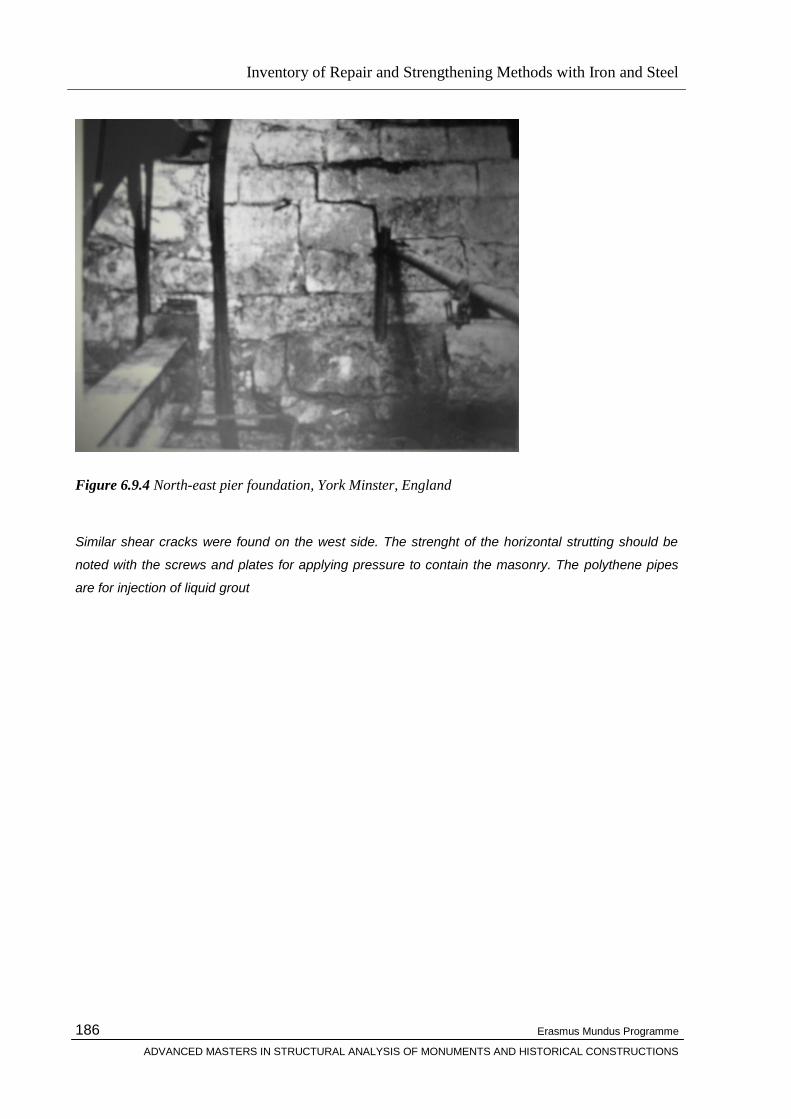
Inventory of Repair and Strengthening Methods with Iron and Steel
Erasmus Mundus Programme
ADVANCED MASTERS IN STRUCTURAL ANALYSIS OF MONUMENTS AND HISTORICAL CONSTRUCTIONS
186
Figure 6.9.4 North-east pier foundation, York Minster, England
Similar shear cracks were found on the west side. The strenght of the horizontal strutting should be
noted with the screws and plates for applying pressure to contain the masonry. The polythene pipes
are for injection of liquid grout
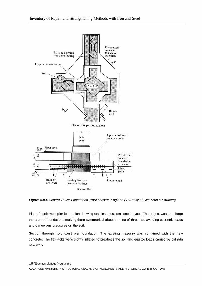
Inventory of Repair and Strengthening Methods with Iron and Steel
Erasmus Mundus Programme
ADVANCED MASTERS IN STRUCTURAL ANALYSIS OF MONUMENTS AND HISTORICAL CONSTRUCTIONS
187
Figure 6.9.4 Central Tower Foundation, York Minster, England (Vourtesy of Ove Arup & Partners)
Plan of north-west pier foundation showing stainless post-tensioned layout. The project was to enlarge
the area of foundations making them symmetrical about the line of thrust, so avoiding eccentric loads
and dangerous pressures on the soil.
Section through north-west pier foundation. The existing masonry was contained with the new
concrete. The flat-jacks were slowly inflated to prestress the soil and equlize loads carried by old adn
new work.

Inventory of Repair and Strengthening Methods with Iron and Steel
Erasmus Mundus Programme
ADVANCED MASTERS IN STRUCTURAL ANALYSIS OF MONUMENTS AND HISTORICAL CONSTRUCTIONS
188
Figure 6.9.5 Enlarged foundations, central tower, York Minster, England (Courtesy of Shepherd
Building Group, Ltd)
A general view showing the enlarged independent foundations of the central piers which are linked to
adjacent nave choir and transept aisle piers. The concrete rings to prevent bursting are above the new
foundation proper. Measuring points are fixed on to each foundation movements being checked each
week. Prestressed stainlee steel reinforcing rods were inserted diagonally under the main piers, 100 to
each pier, in holes drilled through the original masonry.
Drilling Works
Horizontal shots of up to 20 m (66ft) length have been carried out effectievly on the central tower of
York Minster through large block of hard limestone, after preliminary grouting. If a shot went off
alignment, the drill was withdrawn and the hole was grouted with rapid-hardening cement. The drill
used a crown-shaped drilling head with a special guiding mandrel. Horizontal shots of 15 m (49ft)
length in fissured and disintegrated masonry in the Norman foundations had to be re-drilled more than
once with a wide range of dirlled heads.
The 16000 ton central tower is carried by four main columns. Each column has, as its effective
foundation, a cruciform of Norman strip footings. Taking into account eccentricity, the bearing stresses
on the ground are much heavier than desirable. The effective area of each column is increased and
the eccentricity reduced by adding slabs of concrete 2.1 m (6 ft 11in) thick in each re-entrant corner.
The whole compocite foundation is reinforced by post-tensioned 32 mm (1.3 in) diameter stainless
steel rods which form two layers in each elevation. This involves drilling holes up to 15 m ( 49ft)
horizontally through the Norman foundations with a high standard of accuracy.

Inventory of Repair and Strengthening Methods with Iron and Steel
Erasmus Mundus Programme
ADVANCED MASTERS IN STRUCTURAL ANALYSIS OF MONUMENTS AND HISTORICAL CONSTRUCTIONS
189
The centers of the rods are 380 mm (1ft 3in) apart horizontally and 450 mm (1ft 6in) apart vertically in
each direction. However, since one layer in each direction bisects the two layers in the orthogonal
direction, the actual vertical distance between the layers is only 225 mm (9in). Form these figures it
can be seen that the target after 12 to 15 m (40 to 50 ft) of drilling, allowing workable tolerances, is a rectangle
only 300x 225 mm (12x9 in) Such accuracy has proved very difficult to achieve.
For several months, before any drilling was attempted on the foundations, similar requirements had
been carried out at high levels in the Central and Western towers. The walls of these towers have
been protected from further cracking by reinfrocing them horizontally in certain areas with stainless
steel rods. This involved drilling holes 20 m (66ft) in length but more rolerance was allowed than was
later rquired for foundations. The work on the towers, by comparison went very well and success gave
confidence for the drilling below-a confidence which nearly turned to despair when several months
after starting on the foundations drilling, only 8 holes had been succesful out of a total of 38 attempts
(400 to do). The rason why drilling in the walls of the fabric was easier than in the foundations are
based on the two things essential for an accurate drilling:
The nature of the material being drilled
The use of the correct equipment to suit the material
The ideal material is a sound, homogeneous rock containing no fissures or voids. Mass concrete od
course, is equally acceptable.
The Minster fabric, in general, is well-bonded magnesian limestone masonry and where rubble cores
occur, they are well compacted and reasonably well mortared. On the other hand, the Norman mortar
raft is far from ideal, for several reasons [24] .
.

Inventory of Repair and Strengthening Methods with Iron and Steel
Erasmus Mundus Programme
ADVANCED MASTERS IN STRUCTURAL ANALYSIS OF MONUMENTS AND HISTORICAL CONSTRUCTIONS
190
Figure 6.9.7 Drilling bits, York Minster, England (Courtesy: Shepherd Building Group Ltd) All the drill-bead components and assemblies are powered pneumatically for both rotary and rotary
percussive drilling units.Advantages and disadvantages- high speed rotary percussive is the most
economical means of drilling: tungsten carbide tipped bits are much cheaper than diamond crowns.
This type of drilling is fast but demands a homogeneous mass, prefarably of like material, to provide
for accuracy in operation where long holes are required horizontally in masonry.Diamond core drilling
is rather slower and thus more costly, but under adverse conditions in bad materials is more accurate
in maintaining alignment.

Inventory of Repair and Strengthening Methods with Iron and Steel
Erasmus Mundus Programme
ADVANCED MASTERS IN STRUCTURAL ANALYSIS OF MONUMENTS AND HISTORICAL CONSTRUCTIONS
191
Figure 6.9.8 Enlarged foundations, central tower, York Minster, England
After drilling through 15 m of concrete, stone, mortar and wood the hole is lined with a pipe to prevent
local collapse and the tensile stainless steel bars inserted. These were then streched and given a final
tensioning after two months and then grouted. The probes are all ready to receive the liquid grout
injection.

Inventory of Repair and Strengthening Methods with Iron and Steel
Erasmus Mundus Programme
ADVANCED MASTERS IN STRUCTURAL ANALYSIS OF MONUMENTS AND HISTORICAL CONSTRUCTIONS
192
Inventory of Repair and Strengthening Methods with Iron and Steel
Erasmus Mundus Programme
ADVANCED MASTERS IN STRUCTURAL ANALYSIS OF MONUMENTS AND HISTORICAL CONSTRUCTIONS
193
CHAPTER 7
SUMMARY, DISCUSSIONS, CONCLUSIONS ................
7.1 Discussions
Metals were mainly played an auxiliary role in architecture before 1800. They were used for bonding
masonry with dowels and clamps, for tension members with chains strengthening domes, tie rods
across arches to reinforce the vaults, and for roofing, doors, windows, and decoration. Cast iron, the
first metal that could be substituted for traditional structural materials, was used in bridge building as
early as 1779. Its ability to bear loads and to be produced in an endless variety of forms, in addition to
its resistance to fire and corrosion, quickly encouraged architectural adaptations, first as columns and
arches and afterward in skeletal structures. Cast iron has much more compressive than tensile
strength for example, it works better as a small column than as a beam. Cast iron was largely
replaced in the late 19th
century by steel, which is more uniformly strong, elastic, and workable, and its
high resistance in all stresses (i.e tension, compression and bending) can be closely calculated.
7.1.1 Common Problems of exposed Steelwork
Exposed steelwork was (and is) normally given a protective coating of paint. The paint film does
however break down with time under the influence of water, air and ultraviolet light, and once even the
smallest area of metal is bared, corrosion sets in. Because the rust (iron oxide) occupies a higher
position in the galvanic series than iron, the corrosion can, and will, spread under the remaining intact
paint film. Because the rust occupies a greater volume than the steel, the paint film then gets lifted
from the metal.
On surfaces that get washed by rain and dried by wind, this will happen within a certain timespan,
dictated by the resistance of the paint to general atmospheric weathering. In locations on the structure
which are sheltered from the wind, and from which water cannot freely drain, moisture, laden with
atmospheric pollutants such as sulphates and chlorides, will be trapped and remain for prolonged
periods, during which corrosion of the areas that have lost their paint will continue, for much longer
than on the free-draining, wind-dried surfaces. At any one time, corrosion damage will therefore be far
more severe in such moisture traps, even if no great volumes of water are present; moisture from
condensation is enough to generate corrosion.
The detail design of many steel structures, from the first half of the twentieth century or earlier, did
unfortunately not take this into account; moreover, the details that allow moisture to lodge and remain,
also make cleaning and re-painting exceedingly difficult and, sometimes, impossible. An example of
such details is the common truss members of two angles riveted together, back to back, with a gap,
dictated by the thickness of the gusset plates, of only 10 or 12 mm. In such structures corrosion may
sometimes cause significant structural weakening.
Inventory of Repair and Strengthening Methods with Iron and Steel
Erasmus Mundus Programme
ADVANCED MASTERS IN STRUCTURAL ANALYSIS OF MONUMENTS AND HISTORICAL CONSTRUCTIONS
194
Railway station train sheds are among structures, that were subjected to particularly severe conditions
in the past, being exposed to exhaust steam, mixed with smoke containing sulphur dioxide. On the
credit side, they were usually subject to a regular maintenance routine, during which re-painting would
be carried out, as well as circumstances permitted, even if some of the gaps and crevices could not be
properly treated.
7.1.2 Common Problems of Steelwork Encased in Masonry
In buildings with an internal iron or steel structure and external loadbearing walls, the beam ends
would be supported on the walls, usually through a padstone, to a depth of between half and two-
thirds of the wall thickness. They would thus have a fair thickness of masonry protecting them from the
weather. With the introduction of the full steel frame, the external walls could be made thinner and
often, in order to reduce the projection of the steel stanchions inside the building, only a minimum
thickness of masonry was provided on the outside of the stanchions and tie beams. The protection of
the metal, usually given only a token coat of paint, was then heavily dependent on the masonry.
Natural stone and plain brick masonry kept the rainwater away from the steelwork by repelling some of
it, but temporarily absorbing a substantial proportion of it, which it would subsequently release back
into the air by evaporation. In this way it acted like a heavy overcoat, as opposed to the ‗plastic mac‘-
action of modern curtain walling, which needs to be absolutely impermeable. Glazed brick and
terracotta will, unless the pointing is perfect, suffer water penetration by capillary action through the
joints, with the glazing impeding later drying out by evaporation. Heavy corrosion may also have taken
place, due to badly maintained gutters and downpipes. If downpipes are blocked, the gutters overflow
and the water finds its way into the masonry. This also happens when lead-lined or asphalted gutters
are not maintained. The water then finds its way to the (normally unpainted) metal and as the masonry
is never impermeable enough to exclude air, corrosion will then progress, unseen, for some time. The
time when signs of trouble appear depends on how tightly the masonry has been fitted round the
steelwork: As mentioned above, rust occupies a much greater volume than the parent metal. If all
gaps between brick (or stone) and steel are fully filled with mortar, rusting may not start until the lime
or cement has carbonated but after that, the rust will soon fill the pores in the mortar and as more
rust is formed, it will exert pressure on the masonry, which will then crack (Figure 7.1.1a). If, however,
gaps, say 10–20 mm wide, have been left between the flanges of the frame and the back of the
masonry, the rust can have expanded into the gap for a long time (50 years or more) before the gap is
filled, but once this has taken place, the rust will exert pressure on the masonry and crack it (Figure
7.1.1.b). As on the same building there may be gaps in some locations and not in others and as the
width of the gaps may vary between 20 mm and nothing, there
is no way in which a visual inspection of the exterior can establish the existence or the extent of a
corrosion problem on such a building. Another difficulty is that corrosion does not necessarily occur
where the water gets in; it can run down a stanchion, causing little damage, until it finds a ledge on

Inventory of Repair and Strengthening Methods with Iron and Steel
Erasmus Mundus Programme
ADVANCED MASTERS IN STRUCTURAL ANALYSIS OF MONUMENTS AND HISTORICAL CONSTRUCTIONS
195
which it can collect, and this is where rusting occurs. Cracking may also be due to rusting of iron
cramps forming part of the detailing of the masonry cladding, without necessarily indicating corrosion
of the main steel structure. If some cracking is evident, a limited opening up may indicate how far the
rusting extends beyond the cracking in that location, but in that location only. A possible method of
ascertaining an unseen problem would be to carefully drill a core hole
Figure 7.1.1 Rusting steel member encased in masonry: (a) Gaps between steel and masonry fully mortared; (b) Gaps left empty between steel and masonry. perpendicular to the face until the core barrel touches the face of the metal. By inspection of the end of
the core and the bottom of the hole, it should be possible to ascertain the presence and thickness of
any build-up of rust. When reinstating such an inspection hole, one must not create an entry for water
where there was none before. Absolute assurance of the absence of any problem does however, in
principle, require complete removal of the masonry cladding with inevitable consequential damage and
no guarantee that it will be put back as well as it was originally built (leaving aside the difficulty of
procuring matching masonry material to replace that broken during the removal).
7.1.3 Problems with Cavity-ties
Cavity brickwork is found as cladding on multi-storey, framed buildings, as well as in load-bearing
walls of dwelling houses.
On older houses, inadequate corrosion protection of the ties, together with the use of ‗black ash‘
mortar in the outer leaf, can lead to the ties rusting. The ties, then used, were cut from 25 _ 4 mm flat
steel, twisted in the middle and split at the ends; they introduced a substantial iron component in the
bed-joints, and the rusting sometimes cracked the joints.
During the 1960s, ties made of galvanized wire, twisted into a butterfly shape, were introduced.
Corrosion can again be a problem with these, but the main danger in this case is that they rust away

Inventory of Repair and Strengthening Methods with Iron and Steel
Erasmus Mundus Programme
ADVANCED MASTERS IN STRUCTURAL ANALYSIS OF MONUMENTS AND HISTORICAL CONSTRUCTIONS
196
almost completely, leaving the outer leaf with no connection to the backing structure. The most
common defect with this type of cavity wall is, however, the failure of the bricklayer to put in the
required number (usually specified as one for every 45 cm in every third course). Spacings of more
than double the specified are not uncommon and have in some cases led to the outer leaf being
sucked off a façade during high winds.
7.1.4 Cracks Due to Embedded Ironwork
In the past, stone masonry was sometimes built with embedded iron cramps or ‗staples‘, which were
intended to hold together two adjacent stones in areas where tension might occur, temporarily or
permanently. Similarly, where arch or dome thrust needed to be restrained,
tie rods were provided within the thickness of the masonry. In both cases, the iron components were
usually placed in horizontal rebates formed in the top surfaces of the stones and the ends were bent
down into vertical holes.
In the case of dry-jointed masonry , rainwater is almost certain to find capillary paths to the iron and in
combination with atmospheric oxygen cause rusting of the ironwork. This hazard is aggravated in
exposed coastal situations, where salt-laden spray may be carried inland by wind. This is because the
chlorides in the salt accelerate the corrosion (cf. the chloride effect on reinforcement corrosion;
Embedded iron cramps can, if anything, cause more damage in mortar-jointed masonry than in dry-
jointed. This is because the mortar, which originally was alkaline and therefore protected the iron, has
been carbonated by carbon dioxide from the atmosphere and hence has lost its protective function,
whilst it still confines the corrosion products. As rust takes up between 6 and 10 times the volume of
the iron from which it is formed, very great expansive forces are created by the confinement resulting
sometimes in spectacular displacements of large stones and/or gaping cracks.
To protect the ironwork against corrosion, it was often wrapped in thin sheet lead. Alternatively, molten
lead may have been poured around the iron, fixing it in the holes and rebates at the same time as
providing protection. However, the lead wrapping may not have been watertight to begin with or the
mortar joints may have weathered with time and allowed lime-laden rainwater to get to the lead and
corrode it and form pinholes through which water could get at the iron. In either case, the net result is
the same: rust forms and spreads under the lead. The apparent effect is to make the ironwork expand
(and, in the process, split the lead wrapping, if any).
Whilst this has been known to lift the entire structure above the ironwork, with the bed-joint just above
the iron gaping open, it is more common to find that cracks have formed on the face of the stones
(usually along straight horizontal lines) and
whole slivers of stone may have spalled off. Cracks from this cause can often be identified by the
stones below being stained by rusty water leaking out from the iron.The location of embedded
metalwork, even when it is not (yet) causing problems, can usually be found by the use of certain
metal detectors. There are, however, some bricks and some sandstones which contain a significant

Inventory of Repair and Strengthening Methods with Iron and Steel
Erasmus Mundus Programme
ADVANCED MASTERS IN STRUCTURAL ANALYSIS OF MONUMENTS AND HISTORICAL CONSTRUCTIONS
197
amount of iron; this has been known to ‗confuse‘ the instruments, so that they register metal where
none is present and vice versa. They should therefore be ‗calibrated‘ by a small local opening-up.
Similar problems can be caused in steel-framed buildings with masonry cladding.
7.1.5 Radical remedial Treatment of Corrosion
Continuing corrosion requires a supply of oxygen and moisture and, furthermore, the presence of rust
promotes corrosion, whereas the presence of certain other metals, such as zinc may provide some
protection. It follows that to prevent further corrosion one must, as far as possible, exclude air and
water and, to allow for imperfections in the exclusion system, remove existing rust and, preferably,
arrange for some zinc to be in contact with the iron or steel. In principle this means the following
treatment:
1. Identifying and eliminating, as far as possible, the source of the water that is causing the corrosion.
2. All surfaces must be cleaned down to bright metal.
3. A ‗zinc-rich‘ priming paint must be applied immediately.
4. This priming coat must be protected with several coats of water- and airexcluding paint.
Cleaning is most effectively carried out by grit blasting, but even this cannot reach into the narrow
gaps between ‗back-to-back‘ angles and other crevices, resulting from unfortunate detailing, such as
described above. These can only be cleaned by disassembling the whole structure. This would mean
drilling out all rivets and, as riveting is no longer a ‗live‘ trade, re-assembly would have to be done with
some kind of bolt. This would destroy the authenticity and is therefore often not permissible on
historical grounds. That apart, dismantling will almost certainly result in some damage, the repair of
which will add to the already almost prohibitive cost. (An alternative may be to seal the gaps between
the angles with a waterproof compound.) Radical remedial treatment is therefore rarely practicable
and generally it is not justified.
7.1.6 „Palliative‟ Treatment of Corrosion
If an exposed structure has survived 50 or a 100 years without suffering more than moderately severe
corrosion and if it is not, in its future use, going to be subjected to a worse environment than in the
past, cleaning with a de-scaling gun and vigorous wire-brushing will suffice as preparation for a paint
system that will offer adequate protection for a good many years and which will be fairly easily
maintainable (in contrast to the very special paints, referred to above).
For steelwork with ‗heavy‘ masonry cladding, encasement in good quality concrete may be the
answer. The masonry immediately in front of the steel would have to be removed and ‗thinned down‘
to accommodate the concrete casing. The concrete would then be cast on to the cleaned steel and the
masonry subsequently put back. This procedure may however entail some local damage to the
masonry and consequential repair/replacement. Galvanic protection is sometimes advocated. If
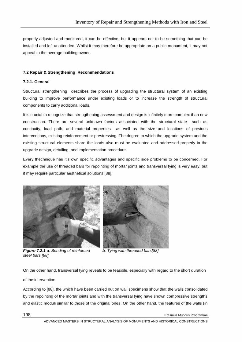
Inventory of Repair and Strengthening Methods with Iron and Steel
Erasmus Mundus Programme
ADVANCED MASTERS IN STRUCTURAL ANALYSIS OF MONUMENTS AND HISTORICAL CONSTRUCTIONS
198
properly adjusted and monitored, it can be effective, but it appears not to be something that can be
installed and left unattended. Whilst it may therefore be appropriate on a public monument, it may not
appeal to the average building owner.
7.2 Repair & Strengthening Recommendations
7.2.1. General
Structural strengthening describes the process of upgrading the structural system of an existing
building to improve performance under existing loads or to increase the strength of structural
components to carry additional loads.
It is crucial to recognize that strengthening assessment and design is infinitely more complex than new
construction. There are several unknown factors associated with the structural state such as
continuity, load path, and material properties as well as the size and locations of previous
interventions, existing reinforcement or prestressing. The degree to which the upgrade system and the
existing structural elements share the loads also must be evaluated and addressed properly in the
upgrade design, detailing, and implementation procedure.
Every thechnique has it‘s own specific advantages and specific side problems to be concerned. For
example the use of threaded bars for repointing of mortar joints and transversal tying is very easy, but
it may require particular aesthetical solutions [88].
Figure 7.2.1 a: Bending of reinforced b: Tying with threaded bars[88] steel bars [88]
On the other hand, transversal tying reveals to be feasible, especially with regard to the short duration
of the intervention.
According to [88], the which have been carried out on wall specimens show that the walls consolidated
by the repointing of the mortar joints and with the transversal tying have shown compressive strengths
and elastic moduli similar to those of the original ones. On the other hand, the features of the walls (in

Inventory of Repair and Strengthening Methods with Iron and Steel
Erasmus Mundus Programme
ADVANCED MASTERS IN STRUCTURAL ANALYSIS OF MONUMENTS AND HISTORICAL CONSTRUCTIONS
199
particular, the weakness of the internal core) led to consider the injection technique as the most
effective intervention.
The transversal tying of walls, strongly reduced vertical and transversal strains at the peak stress. In
particular, the transversal strain, thanks to the restraint effect of the ties, showed an average
reduction, compared to the case of the unstrengthened walls, of about the 50% at the peak stress, and
of about the 90% at the same stress level (see Table 7.2.1 and Figure 7.2.2, where the improvement
in comparison with the injection cases is also shown) [88].
Table 7.3.1: Measured strain for tied and repointed walls, before and after intervention.
Figure 7.3.2: Transversal strain variation at the peak strength after injection and tying [88] The test results show that the best performances can be ascribed to the walls strengthened with
combined techniques, especially when injections are involved in the intervention. The injection of
grouts reveals to be the most effective technique in improving the ultimate load capacity of the walls
(even more than the 50% of the original panels) and in improving the brittle mechanism of failure of
the non consolidated walls. Moreover, increments of the modulus of elasticity
still compatible with the existing structures have been detected, but with significant reductions of the
transversal dilation. Repointing and transversal tying reveals their efficiency mostly in terms of
reduction of deformations. Nevertheless the highest performances is observed for the walls
strengthened by the ―integrated intervention‖, that is by all the three techniques . Thus, the excavation
phase during the repointing execution is effective in bettering the injection procedure, because it
Inventory of Repair and Strengthening Methods with Iron and Steel
Erasmus Mundus Programme
ADVANCED MASTERS IN STRUCTURAL ANALYSIS OF MONUMENTS AND HISTORICAL CONSTRUCTIONS
200
makes easier the hole drilling and the placement of the hoses; on the other hand, the filling of the
joints can prevent the leakage of the grout. Furthermore, the repointing is effective in strengthening
the outer stratum of the external leaves where, to a large extent, the influence of injections can be
regarded as less strong. In the case of tying, the injection of grouts is able to connect the ties to the
inner part of the wall, so that the adherence that develops can increase the confinement effects of the
ties themselves. The studies and various applications prove that it is not possible to consider one
simple technique for strengthening or restoring a masonry structural element or a building without
employing other other techniques.
To discuss in a wider perspective , we must consider the causes of damages to the buildings because
the decissions are affected directly by these causes which would be produced by increasing actions
like forces, deformations, accelerations, or the change in the structural system like removal of a wall or
an arch, addition of a floor, another structural element, or material deterioration thus the reduction of
the strength, the stregnth (decay of the material characteristics, etc
This conveys us to the main idea underlying the philosophy of a succesfull and effective intervention
with the most appropriate techniques for strengthening- restoring an existing historic building decided
according to the specific needs of the building: Proper assesment.
Is it enough to consolidate the walls, or tying the arch or strengthening the foundations? One should
consider the main causes of structural damage or risk of the buildings.
If the cause of the failure arises from the direct actions of the static loads which is the most
common situation for historic masonry buildings, we hould consider the following actions:
strengthening of the material by one of the techniques discussed before (i.e injection,
repointing, transversal tying etc)
stengthening of the main structural elements which a building is made of (i.e stirrups to
contain lateral expansion in pillars and walls; ties or abutments to ensure the thrust in arches
and vaults; etc.)
strengthening of the buildings as a whole.
Whatever the case, it is more effective to improve the general overall structural behaviour of a
building, as a whole, rather than to deal with local problems , and to to ensure good connections
between the main structural elements (wall to wall, wall to floor ) because eccentricities of the loads
and thrusts of vaults are frequent and unavoidable. These connections can usually be achieved by
means of the proper anchorage of the floor structures to the walls and the use of chains, ties, etc.
Other cases of failures may develop due to soil settlements for which the measures to be taken should
be decided accordingly like:
1. Improve the soil‘s behaviour.

Inventory of Repair and Strengthening Methods with Iron and Steel
Erasmus Mundus Programme
ADVANCED MASTERS IN STRUCTURAL ANALYSIS OF MONUMENTS AND HISTORICAL CONSTRUCTIONS
201
2. Modify the pressures under the foundations.
3. Improve the building‘s behaviour.
Modification of the pressure to the soil under foundations can be achieved by the folloeing acrions
which are oftenly combined:
1. modification of the loads;
2. enlargement of the actual foundation;
3. transfer of the load to deeper strata (underpinning).
Reduction of the loads acting on the soils can be simply achieved using procedures such as lightening
of the construction by the demolition of floors, the removal of heavy walls and their substitution with
lighter structures in steel or concrete, or the removal of soil internally and externally along sections of
the perimeter walls and replacing it with lighter materials. Where different settlements and particularly
tilting phenomena have occurred, it is possible to stabilise or even reverse these changes by altering
the load distribution so as to increase pressures in some zones and reduce in others. For the
strengthening to counter the settlement problem sthe concept is based on the strengthening of the
structure by means of:
The formation of a series of boxes or honeycomb-type arrangements, in the basement usually
in reinforced concrete, with solid or perforated walls to form a strong resistant box construction
to reinforce the building.
The insertion of braces and ties to walls or ceilings; ties are very useful for masonry buildings
when there is a tendency for front walls to move out. This type of action is particularly efficient
in buildings like towers where the ratio between the height and the base magnifies the effects
of any small rotations in the foundations.
A general stiffening of the construction as a whole, using additional reinforcement, inserted,
for maximum efficiency, at various levels.
Another main cause of damage to buildings is the seismic actions and the measure to be ataken are
simply:
to improve the structural behaviour;
to reduce the seismic effects.
Although, from a theoretical point of view, to strengthen the structure or to dissipate seismic energy
can result in equivalent safety-level improvements, from a practical point of view, very often the former
route of ‗improving the structural behaviour ‗is not only more reliable but alsoeasier to carry out, rather
than the latter Attention must be paid to the stability of non-structural elements, such as entablatures,
Inventory of Repair and Strengthening Methods with Iron and Steel
Erasmus Mundus Programme
ADVANCED MASTERS IN STRUCTURAL ANALYSIS OF MONUMENTS AND HISTORICAL CONSTRUCTIONS
202
cornices, ridges, spires, etc. using, if need be, specialised connections, such as dowels, cramps, pins.
etc.
For strengthening of of structural elements against seismic actions the following actions are
recommended [89]
a- the ―flexural‖ behaviour of the walls is characterised by cracks mainly concentrated under and over
the windows the wall behaviour can be improved by ensuring good horizontal connections at floor
level. This can be achieved by using ―kerbs‖ formed with steel or synthetic bars injected in the
masonry. Concrete ―kerbs‖ can be structurally useful but often incompatible with the historical
appearance and can be difficult to insert in the building; their use must therefore be limited to
situations where it is not possible to ensure safety levels in more acceptable ways; it is always better,
anyway, to lose the kerbs in the thickness of the masonry. Small x-frame steel braces can be inserted
in the zones under the windows, which are often weak. Vertical bars or cables, often prestressed, may
be placed through drilled holes ideally near the corners of the masonry to eliminate vertical tensile
stresses produced in the walls by high seismic actions.
b- the ―shear‖ behaviour of the walls is characterised by cracks mainly concentrated between the
windows ; it is more favourable than the ―flexural‖ behaviour and usually only occurs where the floor
level connections have been reinforced. to improve the ―shear‖ behaviour it is necessary to strengthen
the masonry panels between the windows. This is generally a more difficult task as usually it requires
major works which tend to affect the architectural value of the building. It usually involves the insertion
of vertical or inclined bars or cables. In exceptional cases high strengthening may be obtained
sandwiching the panel between two thin concrete slabs; this however should be regarded only as an
extreme measure, to be used only when there is no other way of saving the building. Fortunately, if the
masonry is of good quality, the resistance of these panels is sufficiently high by itself or if inadequate,
can be improved simply by consolidating the material.
c-In the ―arch effect‖ behaviour, the weakest zones are near the corners and under the roof, where the
weight may be insufficient to ensure a vertical thrust; the insertions of bars, cables or of small kerbs
may be required to provide an adequate ―thrust‖. Arches and vaults usually require to be strengthened
generally in two situations: where there is a very flat central zone of the arch or vault and where any
large movements of the springers can occur. In the first case, local shear forces and bending
moments may compromise the stability. In the second case chains, ties, buttresses or similar
reinforcement to stiffen the springers may be required to ensure an adequate thrust.
Besides ensuring the strength of each element it is usually necessary strengthening the building as a
whole. The general policy is to ensure the proper working of all structural connections and to improve
the general tensile strength in the critical zones.
Inventory of Repair and Strengthening Methods with Iron and Steel
Erasmus Mundus Programme
ADVANCED MASTERS IN STRUCTURAL ANALYSIS OF MONUMENTS AND HISTORICAL CONSTRUCTIONS
203
7.2.2. Repair of Damage caused by embedded, rusting, Ironwork
Where there are iron cramps or tie bars within 150–200 mm from the face of exposed masonry, it is
futile to hope that some ‗patent‘ resin treatment will effectively stop further rusting, by excluding
moisture. It will get in through weathered pointing in the joints, and the rust that has formed will attract
and hold moisture. Once the corrosion has got hold, the cramps and tie-back bars will somehow have
to be removed. Long bar-cramps in square or polygonal towers and spires can sometimes be partially
removed by drilling out a long core of the masonry, which includes the straight part of the iron bar, its
lead sheath and some of the surrounding stone. If the ends of the bar have been turned down, local
‗open surgery‘is needed to remove them.
Whether the ironwork has to be replaced depends on its original intended function. Where it is clear
that it was originally put in to mitigate the effects of differential settlement, which can now be
considered complete, there should be no need for replacement, provided that such settlement is
unlikely to resume, due to changes in subsoil and groundwater conditions. Where the iron cramps are
tying back cantilevering corniches, they must be replaced. This will require temporary support of the
cantilevering stonework. In church towers where there is a possibility of ringing of heavy or multiple
bells, any reduction of tensile capacity is inadvisable. If any replacement cramps and/or tie bars are
judged to be necessary, they should be of stainless steel and of similar tensile capacity (but not
necessarily the same section) as the iron components that they replace.
7.2.3 Reversibility
There has been a number of instances when arches and vaults have been ‗strengthened‘ by being
suspended by grouted-in hanger bars from a concrete structure built above (and in many cases right
on top of) the original masonry structure. The attraction of such an arrangement is that the concrete
relieving structure can be designed and built to conform today‘s codes of practice, thus circumventing
the ambiguities in the original construction, e.g. if sufficient buttressing is not available, the relieving
structure can be made to act as a beam.
Such interventions preserve the appearance of the underside of the arch or vault, but change the
function from structural to merely decorative. They should therefore be considered as a last resort,
particularly when they involve casting or spraying the concrete directly on to the masonry, as in that
case the intervention becomes irreversible. If provision of such an overlay structure, after careful
consideration, is found to be the only solution, a separation membrane e.g. polyethylene sheeting
should be used.
7.3 Conclusions
Masonry is one of the oldest cosntruction material and tracing back the use of masonry will take us to
the history of the civilization. It is not an exageration to say that masonry represents civilization. From
the first ruble walls of the Stone Age to contemporary brick vener systems, it is masonry the architects
Inventory of Repair and Strengthening Methods with Iron and Steel
Erasmus Mundus Programme
ADVANCED MASTERS IN STRUCTURAL ANALYSIS OF MONUMENTS AND HISTORICAL CONSTRUCTIONS
204
and engineers turn to when performance, solidity, aesthetics are sought the evolution of which is
parallel to the one of civilation.
If a structure is established through the procedures described before to be not sufficient to sustain it‘s
life, decissions should be made on the feasibility of of repair and/or strengthening and on the special
conservation restraints if any with special concern to aesthetics and style.
Viollet-le-Duc gave a clear definition of his understanding of restoration in his Dictionnaire raisonné de
l‟architecture: ‗Restoration: both the word and the activity itself are modern. To restore a building is not
to repair or rebuild it, but to re-establish its original state which must, at a certain moment in time, have
existed.‘ In achieving this objective Viollet-le-Duc had the advantage of skills acquired from the new
science of archaeology, and he knew that the initial step was to carry out a critical examination of the
building.
This study aimed at producing a report (inventory) on stabilization / repair / strengthening materials,
methods and technologies used for the structural restoration of structures including cast iron, wrought
iron and steel members. A detailed literature survey was carried out by reading as many document as
possible using different database including UPC library and after all the courses studied throughout
this advanced master study it may be concluded that regardless of the technique decided to be
applied in a restoration project, it is very important that any repair or strengthening must be based on
a correct diagnosis of the problem by determining the real cause of the observed defects, and if the
cause is still active by eliminating it. Otherwise the repairs will be short-lived. There is a parallel in the
field of medicine: any treatment must be preceded by a correct diagnosis.
Though the study covers the stabilization/repair/strengthening techniques by using iron and steel, the
quote from Carbonara, 1996 applies : Intervention should take into account the modern restoration
and conservation theories which interest both monuments but also all the historic buildings .
It is known that some structural engineers in the past have considerably damaged the character of
some historic buildings, by introducing strengthening devices that opposing the intrinsic mechanics of
the original structure, in order to create a structural system conforming to their conventional textbook
patterns and the codes of practice. There should be a compromise between the architect and the
engineer realizing that unless the structure of the building is sound, its architectural and artistic glories
are bound to perish which will help the architect to understand that the laws of gravity and structural
mechanics apply to all structures, regardless of their antiquity or historic significance; conversely, the
engineer should conceive that older buildings have unique caharacteristics, which are not often found
in modern structures and for the successful operation of structural restoration techniques, it is
essential that the engineer becomes familiar with these symptoms.

Inventory of Repair and Strengthening Methods with Iron and Steel
Erasmus Mundus Programme
ADVANCED MASTERS IN STRUCTURAL ANALYSIS OF MONUMENTS AND HISTORICAL CONSTRUCTIONS
205
REFERENCES
[1] Binda L., Baronio G., Gambarotta L., Lagomarsino S., Modena C., 1999. Masonry
constructions in seismic areas of central Italy: a multi-level approach to conservation,
8NAMC, Austin, USA, CD-ROM.
[2] Binda L., Modena C., Baronio G., Abbaneo S., 1997. Repair and investigation techniques
for stone masonry walls, in Construction and Building Materials, Vol. 11, N.3, pp. 133-
142, 1997.
[3] Binda L., Modena C., Baronio G., Gelmi A., 1994. Experimental qualification of injection
admixtures used for repair and strengthening of stone masonry walls , 10th Int.
Brick/Block Masonry Conf., Calgary, Vol.2, pp. 539-548.
[4] Laefer D., Baronio G., Anzani A., Binda L., 1996. Measurement of grout injection efficacy
for stone masonry walls, Conv. 7NAMC, Notre Dame, USA, Vol. 1, pp. 484-496.
Modena C. Modena C., Zavarise G., Valluzzi M.R. 1997 Modelling of stone masonry walls
strengthened by r.c. jackets, Proc. STRUMAS – 4th Int. Symp. On Computer Methods in
Structural Masonry, Florence, Italy
[6] D. Penazzi , M.R. Valuzzi , A. Ssisi1, L. Bbinda1, C. Modena2 Repair and Srenghening of
Historic Masonry Building in Seismic Areas
[7] Blasi, C., Mémoire sur la stabilité et les lézardes du Panthéon Français, Ministère de la
Culture et de la Communication - Service National des Travaux, Direction du
Patrimoine, December 2005
.
[8] Rondelet, J., Mémoire historique sur le dôme du Panthéon français, divisé en quatre
parties 1797, Paris: Chez du Pont, Imprimeur-Libraire.
[9] Gauthey, E.M., Dissertation sur les dégradations survenues aux piliers du dôme du
Panthéon français et sur les moyens d'y remédier, 1798, Paris.
[10] Rondelet, J., Traité théorique et pratique de l’art de bâtir, 1827-1832, Paris.
[11] Gauthey, E.M., Journal de Physique, November 1774.
[12] Patte, P., Mémoire sur la construction de la coupole projettée pour couronner la
[13] Lodigiani A. ,Macchi G., Technologies for the prestressing rings of the Leaning Tower of Pissa
Structural Analysis of Historical Constructions, 2005 Taylor & Francis Group, London, ISBN 04 1536
379 9
[14] Candela, M., et al. ―L’impiego dei dispositivi a vincolo provvisiorio nel restauro
antisismico di un edificio di culto‖ in L’Ingegneria sismica in Italia1991, 5° Convegno
Nazionale, Palermo, 1991.
[15] Castellano, M.G., ―Innovative technologies for earthquake protection of architectural
heritage‖, in More than two thousand years in the history of architecture, International
ICOMOS Congress, Bethlehem, Palestine, October 2000.
[16] Indirli et al., ―Experimental tests on masonry structures provided with shape memory alloy
antiseismic devices‖ ‖ in Proc. of 12th WCEE, Auckland, New Zealand, 2000.

Inventory of Repair and Strengthening Methods with Iron and Steel
Erasmus Mundus Programme
ADVANCED MASTERS IN STRUCTURAL ANALYSIS OF MONUMENTS AND HISTORICAL CONSTRUCTIONS
206
[17] Croci, G.; Bonci, A.; Viskovic, A. – ―Use of shape memory alloy devices in the Basilica of St.
Francis of Assisi‖ in Shape memory alloy devices for Seismic Protection of Cultural
Heritage Structures, Final Workshop – ISTECH Project, June 2000.
[18] Biritognolo, M.; Bonci, A.; Viskovic, A. – ―Numerical models of masonry façade walls withand
without SMAD’s‖ in Shape memory alloy devices for Seismic Protection of Cultural
Heritage Structures, Final Workshop – ISTECH Project, June 2000.
[19] A F DALY AND W WITARNAWAN (1997). Strengthening of bridges using
external post-tensioning. EASTS '97, Seoul, 29 - 31 October 1997.
[20] LEE, D H (1952). Prestressed concrete bridges and other structures. The Structural Engineer.
Volume 30, Number 12, Dec.
[21] NCE (1996). Pacific bridge collapse throws doubt on repair method. New Civil
Engineer. Magazine of the Institution of Civil Engineers, London, 19 Oct.
[22] XANTHAKOS, P P (1996). Bridge Strengthening and Rehabilitation. Prentice-Hall,New Jersey.
[22] Prestressing steel is manufactured to ASTM Standard A414 (strand) and ASTM Standard 721(bar),
ASTM International, http://www.astm.org
[22] Unbonded monostrand tendons are manufactured to meet the requirements of ACI Standard 421-
06, American Concrete Institute,http://www.concrete.org
[22] Requirements for the components in bonded tendons can be found in PTI’s Acceptance
Standards for Post-Tensioning Systems, Post-Tensioning Institute, http://www.post-tensioning.org
[22] Information on certification of field personnel that install bonded and unbonded tendons can be
found at http://www.ironworkercertification.com
[23] "Reinforced and prestressed masonry" Proceedings, Institution of Civil Engineers, Thomas
Telford Ltd., London, 1982, 163 pp.
[24] Practical design of masonry structures" Proceedings, Institution of Civil Engineers, Thomas
Telford Ltd., London, 1986, 384 pp.
[24] P. B. Lourenço, From Fracture Mechanism to Case Studies: The Issue of Cultural Heri tage
,Universidade do Minho, Departamento de Engenharia Civil, Azurém, P-4800-058 Guimarães,
Portugal. E-mail: [email protected]. Web page:www.civil.uminho.pt/masonry.
[24] D. V. Oliveira , P. B. Lourenço , P. Roca , On the Compressive Strength of Stacked Dry
Masonary
[25] Bernard M. Feilden, Conservation of Historic Buildings, Architectural Press
[26] Maria Rosa Valluzzi
[27] Valluzzi MR, Tinazzi D, Garbin E, Modena C (2003) FEM modelling of CFRP strips bond
behaviour for bed joints reinforcement technique. In: Proc. Of STRUMAS VI, 2003. Rome, Italy, in

Inventory of Repair and Strengthening Methods with Iron and Steel
Erasmus Mundus Programme
ADVANCED MASTERS IN STRUCTURAL ANALYSIS OF MONUMENTS AND HISTORICAL CONSTRUCTIONS
207
Computer Methods in Structural Masonry 6 (Hughes TG, Pande GN (eds) Computers & Geotechnics,
Swansea, UK) pp 149–155
[28] Saisi A, Valluzzi MR, Binda L, Modena C (2004) Creep behavior of brick masonry panels
strengthened by the bed joints reinforcement technique using CFRP thin strips. In: Proc. of
SAHC2004: IV international seminar on structural analysis of historical constructions
– possibilities of experimental and numerical techniques. Padova, Italy, pp 837–846
[29] Anzani A, Binda L, Mirabella G (1999) The role of heavy persistent actions into the behaviour of
ancient masonry. In: Proc. of structural faults + repair – 99, 8th international conference and
exhibition. London, U.K. (on CD-ROM)
[30] Binda L, Modena C, Saisi A, Tongini Folli R, Valluzzi MR (2001) Bed joints structural
repointing of historic masonry structures. In: Proc. of 9th Canadian Masonry
symposium spanning the centuries. Fredericktown, New Brunswick, Canada
[31] Binda L, Modena C, Valluzzi MR, Zago R (1999) Mechanical effects of bed joint steel
reinforcement in historic brick masonry structures. In: Proc. of structural faults + repair – 99, 8th
international conference and exhibition. London, UK
[32] Valluzzi MR, Binda L, Modena C (2004) Mechanical behavior of historic masonry structures
strengthened by bed joints structural repointing. Construct Build Mater 19(1):63–73
[33] Oxford Art Online
http://www.oxfordartonline.com.libezproxy.open.ac.uk/subscriber/article/img/grove/art/F008945
[34] Joques Heyman, The Stone Skeleton , Sturctural Engineering of Masonry Architecture
[35] John Fitchen, The Construction of Gothic Cthedrals, A study of Mediaval Vault Erection
[36] John Fitchen, Building Construction Before Mechanization
[37] The Illustrated Handbook of Architecture , Univeristy of Michigan Libraries
[38] Rowland J. Mainstone Developments in Structural Forms, Architectural Press
[39] S. Frumento, S. Giovinazzi, S. Lagomarsino, S. Podestà, Seismic Retrofitting of Unreinforced
Masonry Buildings in Italy, Department of Structural and Geotechnical Engineering, University of
Genoa, Italy
[40] L. Binda and A. Saisi, State of the Art of Research on Historic Structures in Italy
Dept. of Structural Engineering - Politecnico of Milan. Italy.
[41] Binda L., Modena C., Baronio G., Abbaneo S. (1997), Repair and investigation
tecniques for stone masonry walls, Construction and Building Materials, vol. 11, n. 3,
pp. 133-142.
[42] Binda L., Modena C., Baronio G., Abbaneo S. (1995), Repair and investigation
techniques for stone masonry walls, Proc. Structural Faults + Repair, vol.3, pp. 201-
210.
Inventory of Repair and Strengthening Methods with Iron and Steel
Erasmus Mundus Programme
ADVANCED MASTERS IN STRUCTURAL ANALYSIS OF MONUMENTS AND HISTORICAL CONSTRUCTIONS
208
[43] http://www.sichuaneq2008.org/GeneralInfo.htm
[44] Arya, A., Guidelines for Earthquake Resistant Non-Engineered Construction published by the
International Association for Earthquake Engineering(IAEE), 1986 Tokyo(Japan)
[45] Miha Tomazevic, Earthquake Resistant Design of Masonry Buildings, Imperial College Press
1999
[46] D. D'Ayala, E. Speranza, Single family stone masonry house, World Housing Encyclopedia,
Report/Italy, EERI and IAEE
[47] M. Tomazevic, M. EERI, M. Lutman, P. Weiss, The seismic resistance of historical urban
buildings and the interventions in their floor systems: an experimental study. The Masonry Society
Journal 12 (1), 1993
[48] D'Ayala, Charleson, W., Review of seismic strengthening guidelines for RC buildings in
developing countries, 12th ECEE, Paper No 820
[49] D. D'Ayala, E. Speranza, F. D'Ercole, Single family historic brick masonry house, World Housing
Encyclopedia, Report/Italy, EERI and IAEE
[50] Repair and strengthening guide for earthquake damaged low-rise domestic buildings in Gujarat,
India, GREAT publication, ARUP, June 2001
[51] Construction under seismic condition in the Balkan region. Vol. 5: Repair and Strengthening of
reinforced concrete, stone and brick masonry buildings (UNIDO/UNDP, Vienna, 1983)
[52] Construction under seismic condition in the Balkan region. Vol. 6: Repair and Strengthening of
cultural monuments (UNIDO/UNDP, Vienna, 1984)
[53] Applied Technology Council (ATC- 43 ), Evaluation of earthquake damaged concrete and
masonry wall buildings- Basic procedures manual, FEMA 306, 1998
[54] Applied Technology Council (ATC- 43 ), Evaluation of earthquake damaged concrete and
masonry wall buildings- Technical resources manual, FEMA 307, 1998
[55] Applied Technology Council (ATC- 43 ), Repair of earthquake damaged concrete and masonry
wall buildings- Basic procedures manual, FEMA 308, 1998
[56] Building Seismic Safety Council, FEMA- 274, NEHRP commentary on the guidelines for the
seismic rehabilitation of buildings, 1997
[57] Applied Technology Council (ATC- 40 ), The seismic evaluation and retrofit of concrete
buildings, California Seismic Safety Commission, 1996
[58] Goretti, A., Pasqualle, G., An overview of post-earthquake damage assessment in Italy, National
seismic survey, Department of Civil Protection, Italy
[59] Eurocode 8: Design provisions for earthquake resistance of structures. Part 1-4: General rules-
Strengthening and repair of buildings. ENV 1998-1-4: 1996 (CEN, Brussels, 1996)
Inventory of Repair and Strengthening Methods with Iron and Steel
Erasmus Mundus Programme
ADVANCED MASTERS IN STRUCTURAL ANALYSIS OF MONUMENTS AND HISTORICAL CONSTRUCTIONS
209
[60] Nicolic-Brzev, S., Greene, M., Krimgold, F., Seeber, L., Innovative earthquake recovery in India,
EERI, Learning from earthquakes series, Vol2,1999
[61] M. Tomazevic, M. EERI, M. Lutman, P. Weiss, Seismic upgrading of old brick masonry urban
houses: Tying of walls with steel ties, Earthquake Spectra, Vol 12, No 3, 1996
[62] M. Tomazevic, V. Apih, The strengthening of stone masonry walls by injecting the masonry
friendly grouts, European Earthquake Engineering, Vol 1, 1993
[63] M. Priestley, F. Seible, Design of seismic retrofit measures for concrete and masonry structures,
Construction and building materials, Vol 9, No 6, 1995
[64] D. Olaru, RC and masonry structures: Seismic risk evaluation and RC jacketed strengthening
design procedures, Building research centre, Iasi, Romania, 11th ECEE, 1998
[65] Arnold Hendry, Reinforced and prestressed masonry, Longman Scientific & Technical, 1991
[66] G. Magenes, In-plane cyclic testing of reinforced masonry shear walls, University of Pavia, Italy,
11th ECEE, 1998
[67] D'Ayala, D., The use of bed joint reinforcement to improve the performance of historic masonry
buildings, 5th International Masonry Conference, London, 1998
[68] Pajagde, P., Jawade, S., Gaulkar, M., Kulkarni, S., Evaluation and retrofitting of buildings
damaged in the Jobalpur, India earthquake of 22nd May, 1997, 12th World Conference on Earthquake
Engineering, 2000
[69] Corradi, M., Borri, A., Vignoli, A., Strengthening techniques tested on masonry structures struck
by the Umbria-Marche earthquake of 1997-1998, Construction and Building Materials 16, 2002
[70] Arya, A., Post-earthquake reconstruction in Maharashtra, India, University of Roorkee, India,
11th World Conference on Earthquake Engineering
[71] Arya, A., Seismic retrofitting of stone houses in Marathwara area, India, University of Roorkee,
India, 11th World Conference on Earthquake Engineering
[72] Langenbach, R. Earthquakes. A new look at cracked masonry, Civil Engineering, November
1992
[
73] T. Avdis, Repairs of buildings after the Earthquake: Experiences from Thessaloniki, 1980
[74] Buildings to Resist the Effect of Wind, Vol.3- A Guide for Improved Masonry and Timber
Connections in Buildings, NBS Building Science Series, 1977
[75] M. Priestley, F. Seible, Design of seismic retrofit measures for concrete and masonry structures,
Construction and building materials, Vol 9, No 6, 1995
[76] Verhoef, L., Zijl G., Re-strengthening of brickwork to reduce crack width, Advances in
Engineering Software, Vol 33, 2002 3
[77] Myrto Georgiou, Repairing earthquake damaged buildings, MSc thesis (City University, London,
2000)

Inventory of Repair and Strengthening Methods with Iron and Steel
Erasmus Mundus Programme
ADVANCED MASTERS IN STRUCTURAL ANALYSIS OF MONUMENTS AND HISTORICAL CONSTRUCTIONS
210
[78] M.Chronopoulos, Incorporated steel profiles: A repair/strengthening technique, 7th ECEE,
Athens
[79] M. Cheung, S. Foo, J. Granadino, Seismic retrofit of existing buildings: Innovative alternatives,
Public Works & Government services Canada
[80] K. Cinar, D. Aydin, The sustainability of cultural heritage: two sample houses in Konya,
Architecture of Selcuk University in Konya, Turkey
[81] L. Decanini, A. De Sortis, A. Goretti, R. Langenbach, M. EERI, F. Mollaioli, A. Rasulo,
Masonry building performance in the 2002 Molise earthquake, 2003
[82] Arya, A., Recent developments towards earthquake risk reduction in India, Special edition-
Seismology 2000
[83] Arya, A., Guidelines- Imroving earthquake resistance of housing, Building Materials &
Technology Promotion Council (BMTPC), Ministry of Urban Development and Poverty Alleviation,
India
[84] M. ElGawady, P. Lestuzzi, M. Badoux, A Review of Conventional Seismic Retrofitting
Techniques for, URM 13th International Brick and Block Masonry Conference Amsterdam, July 4-7,
2004 page 1
[85] Detailed Description of Mallorca Cathedral, Asia-wide Programme: EU-INDIA ECONOMIC
CROSS CULTURAL PROGRAMME Project Title: IMPROVING THE SEISMIC RESISTANCE OF CULTURAL HERITAGE BUILDINGS Project Contract N°: ALA/95/23/2003/077-122 Project Beneficiary: UNIVERSIDADE DO MINHO, PORTUGAL Partners: TECHNICAL UNIVERSITY OF CATALONIA, SPAIN CENTRAL BUILDING RESEARCH INSTITUTE, INDIA UNIVERSITÁ DEGLI STUDI DI PADOVA, ITALY
[86] Pere Roca, Studies on the structure of Gothic Cathedrals, Historical Constructions, P.B.
Lourenço, P. Roca (Eds.), Guimarães, 2001
[87] http://www.thyssenkrupp-stainless.com/en/info/applications/architecture/restoration-and-
conservation-work.html
[88] M. R. Valluzzi, F. da Porto and C. Modena, Behaviour of multi-leaf stone masonry walls
strengthened by different intervention techniques, Historical Constructions, P.B. Lourenço, P. Roca
(Eds.), Guimarães, 2001
[89] Giorgio Croci, Strengthening of monuments under the effect of static loads, soil
settlements and seismic actions – Examples, Historical Constructions, P.B. Lourenço, P. Roca (Eds.),
Guimarães, 2001
[90] Poul Beckman and Robert Bowls, Structural Apsects of Building Conservation, 2nd Edition,
Elsevier Butterman Heinemann
Inventory of Repair and Strengthening Methods with Iron and Steel
Erasmus Mundus Programme
ADVANCED MASTERS IN STRUCTURAL ANALYSIS OF MONUMENTS AND HISTORICAL CONSTRUCTIONS
211
Appendix I
Iron and Steel
Iron Man's relationship with iron goes back deep into prehistoric times, and is presently believed to cover at
least seven millennia. Fragments of iron and small iron objects such as beads, blades and decorative
inlays have been found in archaeological sites dating to around 5000 BC, in Irak (Samarra), Iran (Tepe
Sialk) and Egypt (El Gerseh). Later discoveries, corresponding to the early bronze age (3000—2000
BC) and middle bronze age (2000-1600 BC), are all situated in the east and south-east of the
Mediterranean Basin, in Mesopotamia, Turkey, Egypt and Cyprus.
Written evidence of early iron-making activities exists in the form of mural hieroglyphic inscriptions and
papyruses, for example in the Book of the Dead. However, the translation of ancient technical terms
remains uncertain. Some early civilisations do not appear to have recognised iron as being distinct
from copper and refer to it as black copper, in the same manner as unrefined copper. References to
black metal or to metal from the sky could apply to iron or hematite ore, but also to other metals.
Furthermore, the presence of objects made from iron does not necessarily imply the ability to extract
the metal from its ores, since iron also exists in native and particularly meteoritic form, although the
sources are by no means abundant.
The earliest evidence of iron smelting has been found at Hittite excavation sites in Asia Minor, dating
from between 1700 and 1400 BC. However, this does not necessarily mean that iron-making
originated in this region and then spread elsewhere. It is the aim of the present chapter to consider in
more detail the dawn of iron metallurgy.
While the extraction of iron from its ores is closely related to the characteristics of the iron-carbon
system, the practical exploitation of the remarkable properties of iron and steel provides a further
illustration of how technical progress resulted from a combination of empirical observations and
ingenuity. With rudimentary means and limited knowledge, early iron-smiths gradually developed their
skills and know-how, succeeding in manufacturing a wide variety of high quality objects. This is
nowhere more clearly evident than in the art of sword-making throughout the world.
The Three Sources of Iron
The earliest iron used by man was generally meteoritic in origin, as shown by the presence of nickel in
most prehistoric objects, as well as in those from the early and middle bronze ages. The
microstructure of a typical metallic meteorite is shown in Figure 1-1-1.
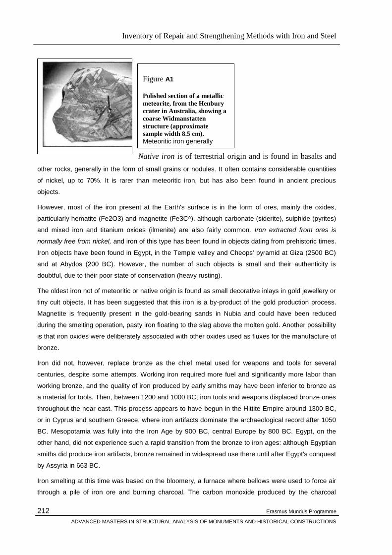
Inventory of Repair and Strengthening Methods with Iron and Steel
Erasmus Mundus Programme
ADVANCED MASTERS IN STRUCTURAL ANALYSIS OF MONUMENTS AND HISTORICAL CONSTRUCTIONS
212
Native iron is of terrestrial origin and is found in basalts and
other rocks, generally in the form of small grains or nodules. It often contains considerable quantities
of nickel, up to 70%. It is rarer than meteoritic iron, but has also been found in ancient precious
objects.
However, most of the iron present at the Earth's surface is in the form of ores, mainly the oxides,
particularly hematite (Fe2O3) and magnetite (Fe3C^), although carbonate (siderite), sulphide (pyrites)
and mixed iron and titanium oxides (ilmenite) are also fairly common. Iron extracted from ores is
normally free from nickel, and iron of this type has been found in objects dating from prehistoric times.
Iron objects have been found in Egypt, in the Temple valley and Cheops' pyramid at Giza (2500 BC)
and at Abydos (200 BC). However, the number of such objects is small and their authenticity is
doubtful, due to their poor state of conservation (heavy rusting).
The oldest iron not of meteoritic or native origin is found as small decorative inlays in gold jewellery or
tiny cult objects. It has been suggested that this iron is a by-product of the gold production process.
Magnetite is frequently present in the gold-bearing sands in Nubia and could have been reduced
during the smelting operation, pasty iron floating to the slag above the molten gold. Another possibility
is that iron oxides were deliberately associated with other oxides used as fluxes for the manufacture of
bronze.
Iron did not, however, replace bronze as the chief metal used for weapons and tools for several
centuries, despite some attempts. Working iron required more fuel and significantly more labor than
working bronze, and the quality of iron produced by early smiths may have been inferior to bronze as
a material for tools. Then, between 1200 and 1000 BC, iron tools and weapons displaced bronze ones
throughout the near east. This process appears to have begun in the Hittite Empire around 1300 BC,
or in Cyprus and southern Greece, where iron artifacts dominate the archaeological record after 1050
BC. Mesopotamia was fully into the Iron Age by 900 BC, central Europe by 800 BC. Egypt, on the
other hand, did not experience such a rapid transition from the bronze to iron ages: although Egyptian
smiths did produce iron artifacts, bronze remained in widespread use there until after Egypt's conquest
by Assyria in 663 BC.
Iron smelting at this time was based on the bloomery, a furnace where bellows were used to force air
through a pile of iron ore and burning charcoal. The carbon monoxide produced by the charcoal
Figure A1
Polished section of a metallic
meteorite, from the Henbury
crater in Australia, showing a
coarse Widmanstatten
structure (approximate
sample width 8.5 cm).
Meteoritic iron generally contains a few percent of nickel, with amounts typically ranging from 5 to 26%, although much larger concentrations
are sometimes found, together with small amounts of cobalt (up to 1%). and traces
of sulphur, phosphorus and
carbon.
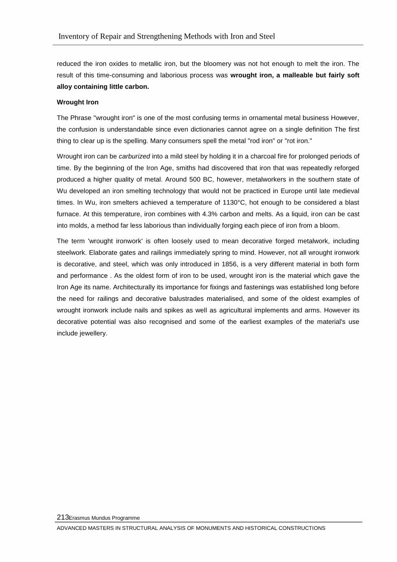
Inventory of Repair and Strengthening Methods with Iron and Steel
Erasmus Mundus Programme
ADVANCED MASTERS IN STRUCTURAL ANALYSIS OF MONUMENTS AND HISTORICAL CONSTRUCTIONS
213
reduced the iron oxides to metallic iron, but the bloomery was not hot enough to melt the iron. The
result of this time-consuming and laborious process was wrought iron, a malleable but fairly soft
alloy containing little carbon.
Wrought Iron
The Phrase "wrought iron" is one of the most confusing terms in ornamental metal business However,
the confusion is understandable since even dictionaries cannot agree on a single definition The first
thing to clear up is the spelling. Many consumers spell the metal "rod iron" or "rot iron."
Wrought iron can be carburized into a mild steel by holding it in a charcoal fire for prolonged periods of
time. By the beginning of the Iron Age, smiths had discovered that iron that was repeatedly reforged
produced a higher quality of metal. Around 500 BC, however, metalworkers in the southern state of
Wu developed an iron smelting technology that would not be practiced in Europe until late medieval
times. In Wu, iron smelters achieved a temperature of 1130°C, hot enough to be considered a blast
furnace. At this temperature, iron combines with 4.3% carbon and melts. As a liquid, iron can be cast
into molds, a method far less laborious than individually forging each piece of iron from a bloom.
The term 'wrought ironwork' is often loosely used to mean decorative forged metalwork, including
steelwork. Elaborate gates and railings immediately spring to mind. However, not all wrought ironwork
is decorative, and steel, which was only introduced in 1856, is a very different material in both form
and performance . As the oldest form of iron to be used, wrought iron is the material which gave the
Iron Age its name. Architecturally its importance for fixings and fastenings was established long before
the need for railings and decorative balustrades materialised, and some of the oldest examples of
wrought ironwork include nails and spikes as well as agricultural implements and arms. However its
decorative potential was also recognised and some of the earliest examples of the material's use
include jewellery.
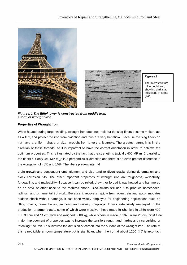
Inventory of Repair and Strengthening Methods with Iron and Steel
Erasmus Mundus Programme
ADVANCED MASTERS IN STRUCTURAL ANALYSIS OF MONUMENTS AND HISTORICAL CONSTRUCTIONS
214
Figure I. 1 The Eiffel tower is constructed from puddle iron, a form of wrought iron. Properties of Wraught Iron
When heated during forge-welding, wrought iron does not melt but the slag fibers become molten, act
as a flux, and protect the iron from oxidation and thus are very beneficial. Because the slag fibers do
not have a uniform shape or size, wrought iron is very anisotropic. The greatest strength is in the
direction of these threads, so it is important to have the correct orientation in order to achieve the
optimum properties. This is illustrated by the fact that the strength is typically 400 MP m_2 parallel to
the fibers but only 340 MP m_2 in a perpendicular direction and there is an even greater difference in
the elongation of 40% and 10%. The fibers prevent internal
grain growth and consequent embrittlement and also tend to divert cracks during deformation and
block corrosion pits. The other important properties of wrought iron are toughness, weldability,
forgeability, and malleability. Because it can be rolled, drawn, or forged it was heated and hammered
on an anvil or other base to the required shape. Blacksmiths still use it to produce horseshoes,
railings, and ornamental ironwork. Because it recovers rapidly from overstrain and accommodates
sudden shock without damage, it has been widely employed for engineering applications such as
lifting chains, crane hooks, anchors, and railway couplings. It was extensively employed in the
production of armor plates, some of which were massive: those made in Sheffield in 1856 were 400
90 cm and 11 cm thick and weighed 3600 kg, while others in made in 1873 were 25 cm thick! One
major improvement of properties was to increase the tensile strength and hardness by carburizing or
―steeling‖ the iron. This involved the diffusion of carbon into the surface of the wrought iron. The rate of
this is negligible at room temperature but is significant when the iron at about 1200 C is in contact
Figure I.2 The microstructure of wrought iron, showing dark slag inclusions in ferrite (iron)
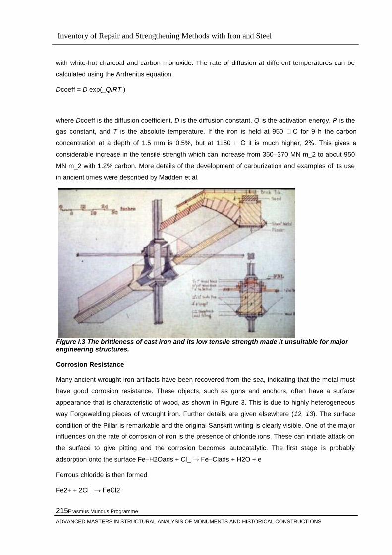
Inventory of Repair and Strengthening Methods with Iron and Steel
Erasmus Mundus Programme
ADVANCED MASTERS IN STRUCTURAL ANALYSIS OF MONUMENTS AND HISTORICAL CONSTRUCTIONS
215
with white-hot charcoal and carbon monoxide. The rate of diffusion at different temperatures can be
calculated using the Arrhenius equation
Dcoeff = D exp(_Q/RT )
where Dcoeff is the diffusion coefficient, D is the diffusion constant, Q is the activation energy, R is the
gas constant, and T is the absolute temperature. If the iron is held at 950 C for 9 h the carbon
concentration at a depth of 1.5 mm is 0.5%, but at 1150 C it is much higher, 2%. This gives a
considerable increase in the tensile strength which can increase from 350–370 MN m_2 to about 950
MN m_2 with 1.2% carbon. More details of the development of carburization and examples of its use
in ancient times were described by Madden et al.
Figure I.3 The brittleness of cast iron and its low tensile strength made it unsuitable for major engineering structures. Corrosion Resistance
Many ancient wrought iron artifacts have been recovered from the sea, indicating that the metal must
have good corrosion resistance. These objects, such as guns and anchors, often have a surface
appearance that is characteristic of wood, as shown in Figure 3. This is due to highly heterogeneous
way Forgewelding pieces of wrought iron. Further details are given elsewhere (12, 13). The surface
condition of the Pillar is remarkable and the original Sanskrit writing is clearly visible. One of the major
influences on the rate of corrosion of iron is the presence of chloride ions. These can initiate attack on
the surface to give pitting and the corrosion becomes autocatalytic. The first stage is probably
adsorption onto the surface Fe–H2Oads + Cl_ → Fe–Clads + H2O + e
Ferrous chloride is then formed
Fe2+ + 2Cl_ → FeCl2

Inventory of Repair and Strengthening Methods with Iron and Steel
Erasmus Mundus Programme
ADVANCED MASTERS IN STRUCTURAL ANALYSIS OF MONUMENTS AND HISTORICAL CONSTRUCTIONS
216
and this is followed by decomposition into the more stable hydrated ferric oxide or rust
2FeCl2 + 4H2O → Fe2O3_H2O + 4HCl + H2
Hence during the formation of rust the chloride is released and the corrosion can continue .
The National Federation of Iron and Steel Manufacturers, submitting evidence in 1931 on the wrought
iron trade, stated that ―owing to its ability to resist all forms of corrosion resulting from atmospheres,
damp and alternative wet and dry conditions, it possesses exceptionally high lasting properties.‖
Iron has been available for building construction from very early times, but until the Industrial
Revolution smelting from the ore was a tedious business carried out on a small scale. All the resulting
products, down to the smallest of nails had to be handwrought. In consequence the material was used
sparingly. However, as supplies of good quality timber ran short improved methods of smelting
developed and iron in the form of straps, coach screws and the like, gradually replaced the fine timber
joinery of earlier constructions. Unfortunately for us today it was sometimes used instead of more
stable metals like bronze to make cramps and ties for masonry work, with consequent failures that
have proved very costly to correct.
Casting iron has also been a technique known for many hundreds of years. In building, castings were
not in common use until the Industrial Revolution of the late 18 th century. Methods had been
developed mainly in the production of military ordnance but by the 1770s a wide variety of standard
castings were available to buildings including, firegrates, chimney pots, railings, windows, sash
weights, locks, latches and hinges, and many others.
The structural use of iron was developed at the same time both as wrought and cast
work. Such was the demand for structural ironwork that in the 1840s rolling mills were built to produce
standard profiled sections, thus eliminating the time consuming cutting and rivetting that had
previously been necessary to build up structural sections. The expansion of the railway system and
the building of iron ships resulted in enormous expansion of the industry. Complete iron buildings were
constructed – the great train sheds, and conservatories everywhere with of course the most famous of
all being The Crystal Palace (1850). The prime example in Northern Ireland is the Palm House in the
Botanic Gardens, Belfast. Standard buildings were shipped all over the world and every town of any
size could boast its public lavatory, bandstand and its decorative street lamps.
Techniques of blending in other minerals to give increased strength and durability were perfected and
in 1866 the first standard rolled steel joists were available. In recent years welding has taken the place
of rivetting. Old wrought iron is very pure and when exposed to the weather forms a skin of black oxide
which protects it against further decay.

Inventory of Repair and Strengthening Methods with Iron and Steel
Erasmus Mundus Programme
ADVANCED MASTERS IN STRUCTURAL ANALYSIS OF MONUMENTS AND HISTORICAL CONSTRUCTIONS
217
Dowels rivets and bolts
Rivets and bolts transmit load by a combination of bearing pressure, shear and friction on the interface
between the components being joined.
The structural principle of the rivet and the bolt is just the same as that of the traditional dowel or peg.
In essence, whenever it is desired to transfer load from one plate to another, the method is to drill a
hole in each plate and then insert a circular bar through these holes. The system relies on the
pressure at the interface of the plate and the bar to transfer load and also on the shear stresses in the
cross section of the bar. Iron and steel have adequate shear strength so that simply increasing the
cross sectional area increases the capacity of the bar. To get adequate bearing between the bar and
the plate, the ductile character of wrought iron and steel helps the action of the joint. The holes drilled
in the plates have in practice to be slightly larger than the bar. If the circle of the bar and the circle of
the hole remained perfect, they would only touch at a point. With wrought iron and steel connections,
both bar and hole will distort significantly to give a larger area of contact. This principle is used for the
dowel, the bolt and the rivet, but it was the rivet which was the predominant means of connecting
wrought iron and steel from the mid-19th to the mid-20th century.
Figure I.4 Flow of forces between steel plates connected by a bar

Inventory of Repair and Strengthening Methods with Iron and Steel
Erasmus Mundus Programme
ADVANCED MASTERS IN STRUCTURAL ANALYSIS OF MONUMENTS AND HISTORICAL CONSTRUCTIONS
218
This curious diagram is an attempt to illustrate the flow of forces between steel plates connected by a
bar. The principle is the same whether the bar is a dowel, a rivet or a bolt. The lower diagram shows
the forces flowing through the plate going around the hole cut in the plate and concentrating behind
the bar. It should be apparent that at the cross section of the plate that goes through the hole, the
stresses are most heavily concentrated. Also that for a reasonable contact area between the plate and
the bar, a degree of ductile deformation is required. Were the hole in the plate and the bar to remain
perfectly circular they would touch only at a point. The positive virtue of a ductile material like steel or
wrought iron is that by deforming by quite small amounts it spreads the loading over a reasonable
area. The upper diagram is a section through the bar showing the transfer of load between the plates
and the sections of the bar that have to transfer the load by shear stresses. In order to make the
diagram clearer and to give room to indicate the shear planes the plates are shown slightly apart. In
practice of course, rivets and bolts clamp the plates together. Indeed the friction between the plates
gave traditional joints added strength and it is utilised by modern high strength friction grip bolts.
Rivets make very effective connections between components in both wrought iron and steel.
In essence, the rivet is simply a bar with its ends hammered over to prevent it slipping out of the hole.
This is easy to do with soft metals like gold, silver, or copper and has been a traditional method of
jointing since prehistory. It was impossible to achieve with cast iron because cast iron cannot be
squashed, it simply fractures. It is a very effective way of joining ductile metals such as wrought iron
and steel. Rivets were heated in portable braziers and held in position with tongs while the protruding
end was bashed over with a big hammer to form strong reliable and positive fixings. In fact, the
connection had more strength than simply the shear across the cross section of the rivet since the
hammering of the head gripped the plates together and load could be transferred through friction
between the plates. Also, the heat and pressure would often induce some pressure welding if the
conditions were favourable.
The Eiffel Tower used 2.5 million rivets. On site they were fitted by this type of four person team. The
rivet was heated to red heat in a portable brazier and transferred from brazier to pre-drilled hole by the
person holding it in position with the tongs. Finally while restrained at the far side it was beaten with a
hammer to form the fixing head. Look at any large scale nineteenth century structure and consider the
man power and organisation required.

Inventory of Repair and Strengthening Methods with Iron and Steel
Erasmus Mundus Programme
ADVANCED MASTERS IN STRUCTURAL ANALYSIS OF MONUMENTS AND HISTORICAL CONSTRUCTIONS
219
Figure I.5 The change from cast iron, with elements that fitted together, to wrought iron, joined by rivets, had a significant effect on the appearance of joints. In terms of the visual expression of the joint, the change from cast to wrought iron was a step
backwards. The relation between the parts was limited by the overlapping of flat surfaces. While this
was ideal for the fabrications of steam boilers, it made the connection of columns and beams, struts
and ties more difficult. Initially, sections were small in size and restricted in profile to flats, tees and
angles. Larger sections would be made up from combinations of these basic profiles, and here there
was scope for richer and more varied joint design. As the 19th century progressed, the introduction of
steel and the development of the industry meant that the rolled sections got larger and the jointing
tended to be cruder.
This column head is a particularly interesting juxtaposition of a timber roof purlin with localised
increase in depth, a wrought iron edge beam made up from riveted angles and flats, cast iron
decorative brackets with both opposing curves fixed by bolts and a slender cast iron column.
Figure I.6 Rivet patterns at joints contributed to the visual interest of large structures.

Inventory of Repair and Strengthening Methods with Iron and Steel
Erasmus Mundus Programme
ADVANCED MASTERS IN STRUCTURAL ANALYSIS OF MONUMENTS AND HISTORICAL CONSTRUCTIONS
220
The most visually interesting structures of this period tended to be the very large showpiece structures
built for the great exhibitions. Eiffel's great tower for the Paris exhibition of 1888 was a tour de force of
joint design. As the scale of the structures got larger, it was not sensible to increase the size of the
rivets, there just had to be more of them. At close quarters, the pattern of the uncountable numbers of
rivets arranged in consciously designed patterns gives human scale to the vast structure. The care
with which the geometry of these patterns was organised showed that engineers like Eiffel were as
alive to the potential of rewarding detailed design as any architect. The Gallery of Machines for the
same exhibition was not only a gigantic enclosure of space, but its structure was built up from riveted
sections in a way that demonstrated a controlled richness of detail that can still be admired in the
famous photograph a hundred years later.
5.2.2 Steel
Steel is composed of iron and carbon. The iron is extracted from iron ores, mined and then refined to
remove the oxygen content.
Part of the refining process is to remove oxygen from these ores by heating them with coke and
limestone to a temperature of about 1600° C in a blast furnace
After reducing the iron oxide the resultant material is pig or cast iron, which is brittle. Some carbon
remains in addition to other unwanted elements and these must be reduced by further refinement
before the material becomes steel. The carbon content of steel is crucial to its strength and is usually
lower than 2.11%. A controlled system of oxidisation is used to manipulate the carbon content. Other
impurities must be removed from the melt in order to achieve the correct composition. Plain carbon
steels are those in which the only other element remaining is manganese.
Figure I.7 After the iron has been extracted from iron oxide it is known as 'pig' or 'cast' iron.

Inventory of Repair and Strengthening Methods with Iron and Steel
Erasmus Mundus Programme
ADVANCED MASTERS IN STRUCTURAL ANALYSIS OF MONUMENTS AND HISTORICAL CONSTRUCTIONS
221
The iron oxide is reduced either directly by the oxide combining with carbon to form iron and carbon
monoxide, or indirectly by combining with this newly formed carbon monoxide to form iron and carbon
dioxide. In this state the material is known as pig or cast iron.
The pig iron must be further refined to reduce the carbon content and the other unwanted elements
before the material can be categorised as a particular steel.
After this process there is always some carbon left in the solid iron
formed amounting to about 4% by weight. The high carbon content of
cast iron results in a material which is brittle and cannot take large
tensile stresses. In addition there is a total of about 6% of other
unwanted elements, including silicon, manganese, sulphur and
phosphorous in unmeasured quantities.
Figure I.8 Refining iron into steel requires the re-melting of the iron in a steelmaking furnace
with a large oxygen input.
In steelmaking the impurities in the melt have to be removed before the correct composition can be
achieved. These include phosphorous and silicon (which make steel hard and induce brittleness), and
sulphur (which can cause cracking in poured castings and welds).
A fundamental distinguishing property of steel is its great strength which depends partly upon the
carbon content.
Most steels have carbon contents far lower than 2.11%. This figure marks the critical maximum where
in the processing of the material, at 900° C, a complete phase change can occur. Above this level of
carbon content, an iron-carbon alloy becomes more brittle taking on the type of performance
associated with cast irons. The manipulation of the carbon content is carried out by controlled removal
by oxidation.
This range of iron-carbon steels are referred to as plain carbon steels as the only other element
present is manganese, present in up to 1.6% by weight and left in the metal from de-oxidation and de-
sulphurisation processes. The addition of any other elements will bring the metal into the metallurgical
category of alloy steels. (The general term alloy steels in the industry refers to those steels which have
contributions from other elements amounting to 5% by weight and over.)
The mechanical properties of steel
The alloys and the heat treatment used in the production of steel result in it having different values and
strengths. Testing must be accurate to determine the properties of the steel and to ensure adherence
to standards.
Different steels have different values of strength and toughness depending on the alloys made and the
heat treatments used. Testing methods are important to determine values and to ensure that
Inventory of Repair and Strengthening Methods with Iron and Steel
Erasmus Mundus Programme
ADVANCED MASTERS IN STRUCTURAL ANALYSIS OF MONUMENTS AND HISTORICAL CONSTRUCTIONS
222
standards are adhered to. Methods of testing determine the yield strength, ductility and stiffness
through tensile testing, toughness through impact testing, and hardness through resistance to
penetration of the surface by a hard object.
Tensile testing is a method of evaluating the structural response of steel to applied loads, with the
results expressed as a relationship between stress and strain.
Specially shaped specimens of steel are subjected to a tensile force which gradually elongates the
steel. The force is increased and the extension of the steel carefully measured.
The stress on the metal is evaluated by dividing the value of the force applied by the cross-sectional
area of the specimen.
Stress = LOAD in Newtons / CROSS-SECTIONAL AREA of specimen in mm2
Strain is measured by calculating the increase in length of the specimen as a proportion of the original
length.
Strain = INCREASE IN LENGTH in mm / ORIGINAL LENGTH in mm
The relationship between stress and strain is a measure of the elasticity of the material.
If a load is applied to a material, and that material fully recovers, that is it returns to its original length
once the load is removed, the elastic limit of the material has not been reached. However, if the
material does not recover on removal of the load, it must have exceeded its elastic limit and will be
said to have deformed permanently and started to behave plastically.
The elastic behaviour is characterised as the ratio of stress to strain, and is referred to as Young's
modulus.
The elastic behaviour is characterised as a relationship between the stress applied and the resultant
strain, and is expressed mathematically as:
STRESS / STRAIN
otherwise known as Young's modulus. This relationship allows comparisons to be made between
different materials.
As the value of Young's modulus changes between materials, so then does their elastic behaviour,
which is a real indicator of their stiffness. Steel has a high value of Young's modulus which is about
205 kN/mm2 (approximately three times the value for aluminium).
The distinction between elastic and plastic behaviour can be seen from the stress-strain curve.
To explain this behaviour more fully, stress is plotted against strain in the following figure.
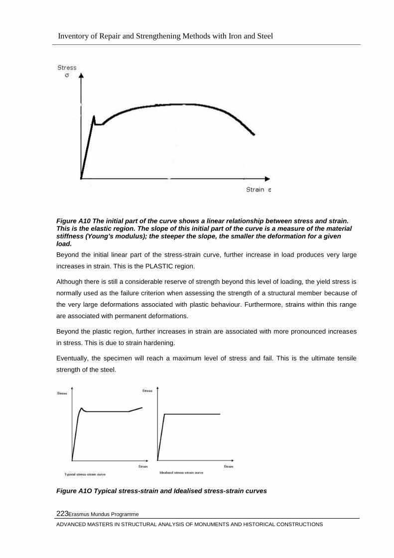
Inventory of Repair and Strengthening Methods with Iron and Steel
Erasmus Mundus Programme
ADVANCED MASTERS IN STRUCTURAL ANALYSIS OF MONUMENTS AND HISTORICAL CONSTRUCTIONS
223
Figure A10 The initial part of the curve shows a linear relationship between stress and strain. This is the elastic region. The slope of this initial part of the curve is a measure of the material stiffness (Young's modulus); the steeper the slope, the smaller the deformation for a given load.
Beyond the initial linear part of the stress-strain curve, further increase in load produces very large
increases in strain. This is the PLASTIC region.
Although there is still a considerable reserve of strength beyond this level of loading, the yield stress is
normally used as the failure criterion when assessing the strength of a structural member because of
the very large deformations associated with plastic behaviour. Furthermore, strains within this range
are associated with permanent deformations.
Beyond the plastic region, further increases in strain are associated with more pronounced increases
in stress. This is due to strain hardening.
Eventually, the specimen will reach a maximum level of stress and fail. This is the ultimate tensile
strength of the steel.
Figure A1O Typical stress-strain and Idealised stress-strain curves
Inventory of Repair and Strengthening Methods with Iron and Steel
Erasmus Mundus Programme
ADVANCED MASTERS IN STRUCTURAL ANALYSIS OF MONUMENTS AND HISTORICAL CONSTRUCTIONS
224
Strength is a very important characteristic of steel, but other properties must also be considered when
considering structural performance.
The yield strength represents the point where behaviour changes from elastic to plastic. The ultimate
tensile strength is the end point of the stress-strain curve representing rupture of the material. Both
yield strength and ultimate tensile strength can be increased by altering the chemical composition of
the steel - particularly the carbon content.
Yield strength can also be improved by mechanically working the steel, although this reduces its
ductility - the ability of the steel to sustain high strains prior to failure
At very cold temperatures some steels may lose ductility.
Under some conditions steel may exhibit a brittle, rather than ductile, mode of failure. This is not
normally a problem in building structures since modern steels are manufactured so as to avoid such
behaviour. However, in extremely cold conditions - for instance exposed steelwork where
temperatures start to fall well below 20 C, the brittleness of steel will increase rapidly.
Steels with high carbon contents are more vulnerable under stress, and stress concentrations due to
imperfections or details should be avoided.
In these low temperature conditions steel alloys are carefully specified; typically the manganese-
carbon ratio is increased and the nickel content reduced, and specialist advice must always be sought.
The behaviour of steel is also notch-sensitive. Fixing details which can impose defects on the steel, for
instance from screw threads, must therefore be avoided.
History of Stainless Steel
The "discovery" of stainless steel occured in the 1900 to 1915 time period. However, as with many
discoveries, it was the accumulated efforts of several individuals that actually began in 1821. That
year a Frenchman named Berthier found that iron when alloyed with chromium was resistant to some
acids. Others studied the effects of chromium in an iron matrix, but using a low percentage of
chromium. To be stainless steel, the chromium content needs to be at least 10.5%. In 1872, Messrs.
Woods and Clark applied for a British patent for what they identified as an acid and weather resistant
alloy containing 30 to 35% chromium and 1.5 to 2% tungsten. Then, in 1875, another Frenchman
named Brustlein recognized the importance of carbon levels in addition to chromium. Stainless steels
need to have a very low level of carbon at 0.15%. While many others investigated the chromium/iron
composition, the difficulty in obtaining the low carbon levels persisted for many years until low carbon
ferrochrome became commercially available.
In 1904, Leon Guillet published research on alloys with composition that today would be known as
410, 420, 442, 446 and 440-C. In 1906, he also published a detailed study of an iron-nickel-chromium
alloy that is the basic metallurgical structure for the 300 series of stainless steel. In 1909, Giesen
published in England a lengthy account on the chromium-nickel (austenitic 300 series) stainless
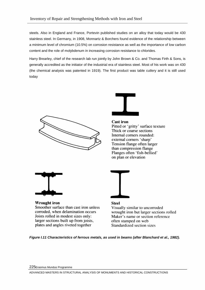
Inventory of Repair and Strengthening Methods with Iron and Steel
Erasmus Mundus Programme
ADVANCED MASTERS IN STRUCTURAL ANALYSIS OF MONUMENTS AND HISTORICAL CONSTRUCTIONS
225
steels. Also in England and France, Portevin published studies on an alloy that today would be 430
stainless steel. In Germany, in 1908, Monnartz & Borchers found evidence of the relationship between
a minimum level of chromium (10.5%) on corrosion resistance as well as the importance of low carbon
content and the role of molybdenum in increasing corrosion resistance to chlorides.
Harry Brearley, chief of the research lab run jointly by John Brown & Co. and Thomas Firth & Sons, is
generally accredited as the initiator of the industrial era of stainless steel. Most of his work was on 430
(the chemical analysis was patented in 1919). The first product was table cutlery and it is still used
today
Figure I.11 Characteristics of ferrous metals, as used in beams (after Blanchard et al., 1982).

Inventory of Repair and Strengthening Methods with Iron and Steel
Erasmus Mundus Programme
ADVANCED MASTERS IN STRUCTURAL ANALYSIS OF MONUMENTS AND HISTORICAL CONSTRUCTIONS
226
Table A1 Material properties given by Twelvetrees ( from CIRIA ‘Structural
Renovation of Traditional Buildings’, Report 111, 1986)
Table A2 Safety factors, recommended by Twelvetrees (after CIRIA, 1986)

Inventory of Repair and Strengthening Methods with Iron and Steel
Erasmus Mundus Programme
ADVANCED MASTERS IN STRUCTURAL ANALYSIS OF MONUMENTS AND HISTORICAL CONSTRUCTIONS
227
Figure I.12 Cross-sections of hollow cast iron columns, showing possible degrees of imperfection ( from Blanchard et al., 1982).

Inventory of Repair and Strengthening Methods with Iron and Steel
Erasmus Mundus Programme
ADVANCED MASTERS IN STRUCTURAL ANALYSIS OF MONUMENTS AND HISTORICAL CONSTRUCTIONS
228
Inventory of Repair and Strengthening Methods with Iron and Steel
Erasmus Mundus Programme
ADVANCED MASTERS IN STRUCTURAL ANALYSIS OF MONUMENTS AND HISTORICAL CONSTRUCTIONS
229
Appendix II
Strengthening of Bridges Using External Post-tensioning
The use of external post-tensioning for the strengthening of existing bridges has been used in many
countries since the 1950s and has been found to provide an efficient and economic solution for a wide
range of bridge types and conditions. The technique is becoming more and more preferable because
of the speed of construction and the minimal disruption to traffic flow.
In response to the demand for faster and more efficient transportation systems, there has been a
steady increase in the weight and volume of traffic using national highway systems throughout the
world. As well as increases in legal vehicle loads, the over-loading of vehicles is a common problem
and this must also be considered when designing or assessing bridges. In response to increased
traffic flow, bridge widening is often carried out to increase the capacity of the road network. As a
result, many bridges are now required to carry loads significantly greater than their original design
loads. This trend is very pronounced in developing countries such as Indonesia as a result of the
accelerated regional development which has taken place over the last two decades. In many areas,
the road system provides the only means of transporting goods and people and is vital for the survival
and prosperity of whole regions. Minor roads which were originally constructed for light traffic are now
required to provide access for modern heavy goods vehicles and roads are continuously being, up-
graded to cope with the increased demands. Bridges are a critical part of this re-classification. Even
bridges which have been designed using appropriate loading specifications can be under-strength for
other reasons. Bad detailing, other design faults, and general wear and tear can impair structural
performance. Deterioration of bridges due to steel corrosion, corrosion of reinforcement, attack by
chemicals or pollution, imnpact damage from vehicles, all lead to loss of strength. Loss of prestress
due to creep and relaxation also results in strength loss. Again, these problems can be accentuated in
developing countries where bridge maintenance is often neglected, deterioration rates can be higher
due to high temperatures, high humnidity and pollution, and the quality of site practice may be low.
Many bridges which were designed to previous loading specifications or which have suffered damage
or deterioration are now inadequate for modern heavy goods vehicles. As a result, bridge owners and
manager are faced with the choice of restricting traffic or carry out rehabilitation. When this is
combined with the growing competition for the funding of infrastructure projects, there is great pressure
to keep bridges in service and minimising capital and maintenance expenditure. Bridge strengthening as
an alternative to complete replacement can provide an effective and economic solution in appropriate
situations. In particular, traffic management costs can be considerably reduced especially in cases
where rehabilitation can be scheduled to avoid complete closure of the carriageway.
Selection of appropriate strengthening technique The selection of an appropriate method for
strengthening a particular bridge depends on a number of factors. The type of structure, the
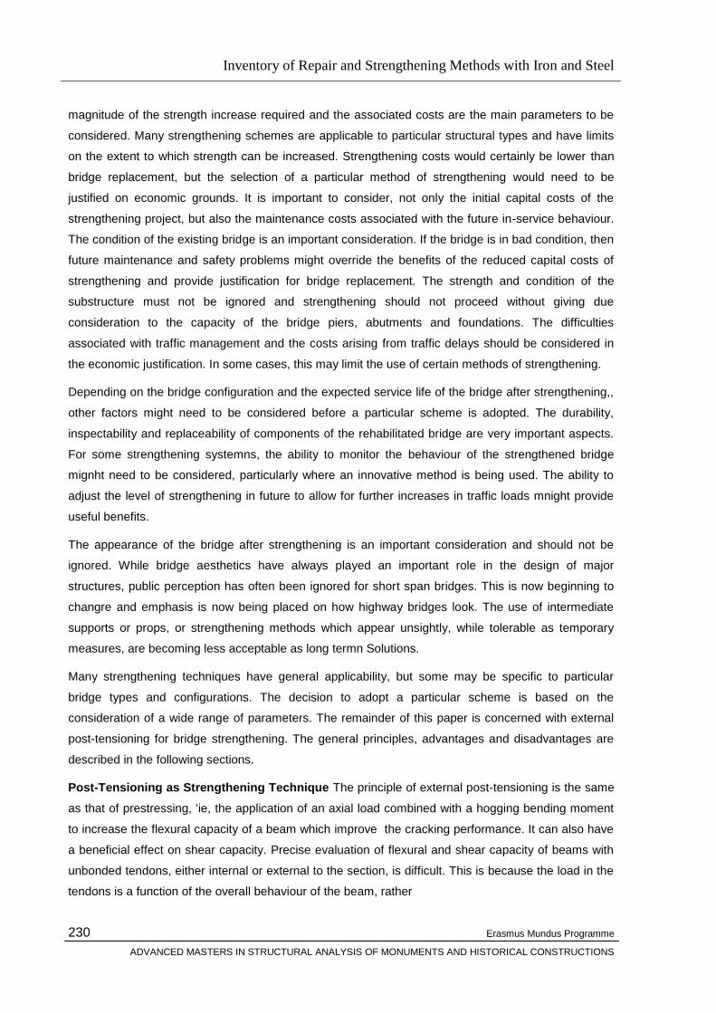
Inventory of Repair and Strengthening Methods with Iron and Steel
Erasmus Mundus Programme
ADVANCED MASTERS IN STRUCTURAL ANALYSIS OF MONUMENTS AND HISTORICAL CONSTRUCTIONS
230
magnitude of the strength increase required and the associated costs are the main parameters to be
considered. Many strengthening schemes are applicable to particular structural types and have limits
on the extent to which strength can be increased. Strengthening costs would certainly be lower than
bridge replacement, but the selection of a particular method of strengthening would need to be
justified on economic grounds. It is important to consider, not only the initial capital costs of the
strengthening project, but also the maintenance costs associated with the future in-service behaviour.
The condition of the existing bridge is an important consideration. If the bridge is in bad condition, then
future maintenance and safety problems might override the benefits of the reduced capital costs of
strengthening and provide justification for bridge replacement. The strength and condition of the
substructure must not be ignored and strengthening should not proceed without giving due
consideration to the capacity of the bridge piers, abutments and foundations. The difficulties
associated with traffic management and the costs arising from traffic delays should be considered in
the economic justification. In some cases, this may limit the use of certain methods of strengthening.
Depending on the bridge configuration and the expected service life of the bridge after strengthening,,
other factors might need to be considered before a particular scheme is adopted. The durability,
inspectability and replaceability of components of the rehabilitated bridge are very important aspects.
For some strengthening systemns, the ability to monitor the behaviour of the strengthened bridge
mignht need to be considered, particularly where an innovative method is being used. The ability to
adjust the level of strengthening in future to allow for further increases in traffic loads mnight provide
useful benefits.
The appearance of the bridge after strengthening is an important consideration and should not be
ignored. While bridge aesthetics have always played an important role in the design of major
structures, public perception has often been ignored for short span bridges. This is now beginning to
changre and emphasis is now being placed on how highway bridges look. The use of intermediate
supports or props, or strengthening methods which appear unsightly, while tolerable as temporary
measures, are becoming less acceptable as long termn Solutions.
Many strengthening techniques have general applicability, but some may be specific to particular
bridge types and configurations. The decision to adopt a particular scheme is based on the
consideration of a wide range of parameters. The remainder of this paper is concerned with external
post-tensioning for bridge strengthening. The general principles, advantages and disadvantages are
described in the following sections.
Post-Tensioning as Strengthening Technique The principle of external post-tensioning is the same
as that of prestressing, 'ie, the application of an axial load combined with a hogging bending moment
to increase the flexural capacity of a beam which improve the cracking performance. It can also have
a beneficial effect on shear capacity. Precise evaluation of flexural and shear capacity of beams with
unbonded tendons, either internal or external to the section, is difficult. This is because the load in the
tendons is a function of the overall behaviour of the beam, rather

Inventory of Repair and Strengthening Methods with Iron and Steel
Erasmus Mundus Programme
ADVANCED MASTERS IN STRUCTURAL ANALYSIS OF MONUMENTS AND HISTORICAL CONSTRUCTIONS
231
than just depending on the strain distribution at a particular critical section. Many national and
international codes present methods of determining, capacity but these are based primarily on
laboratory results obtained from tests on beams with internal tendons. Post-tensioning as a means of
strengthening existing bridges has been in use since the 1950s and there are many examples of its
use throughout the world. In the many situations where the technique has been applied, the prestress
is applied through prestressing cables, either single or grouped strand. In some applications, the
stress has been applied through high tensile bars, jacked either using hydraulic jacks or with fine
screw threads. In a few cases the stress is applied using more unconventional techniques. For
example, stress in a tendon can be developed by anchoring a straight the tendon in place and
imposing a deflection at mid-span. The deflection is then retained by fixing the deflected point.
Prestress can also be developed by applying a load to the structure to cause overall deflection prior to
anchoring the tendons or bars. Specific examples of these different applications are given by
Xanthakos (1996). External post-tensioning can be used to improve the serviceability behaviour of
existing bridges. As in prestressed construction, the method can be used to delay or prevent the onset
of cracking in concrete bridge decks. It can also be used to reduce or close preexisting cracks. This
improvement in cracking behaviour also increases resistance to reinforcement corrosion. The
increased stiffness provided by external post-tensioiningy can reduce in-service deflections and
vibrations. The stress range can also be reduced and the fatigue performance can be improved. The
presence of a deformation or sag in a bridge can be reduced or removed.
Strengthening of Beam Type Bridges
External post-tensioning as been applied most generally to beam type bridges. The tendons can be
straight or draped uising deviators depending on the particular requirements. Various profiles can be
adopted to suit the required combination of axial load and bendinig. Additional compressive members
can be introduced if the additional compression stressed imposed on the bearn are not desirable.
External post-tensioning, can be used to improve the performance of any kind of beam bridge, be it
timber, reinforced concrete, prestressed concrete, steel or composite. The main reason for its use has
been to provide increased flexural strength required because of under-design, increased traffic
loading, loss of structural strength due to deterioration or to correct serviceability problems. In
particular, the application to prestressed beams is appropriate where losses in initial prestress due to
creep, relaxation or corrosion can be restored. The technique can also be used to increased the shear
strength although vertical prestress, described later, can be more appropriate in correcting shear
deficiencies. It is possible to use post-tensioning, to change the structural behaviour in order to
increase strength. For example, the strengthening object might be to provide continuity across a
support, ie, change a series of simply supported spans to a continuous one. It can also be used to
provide continuity across an unsupported joint, for example, across the joint between two cantilever
spans.

Inventory of Repair and Strengthening Methods with Iron and Steel
Erasmus Mundus Programme
ADVANCED MASTERS IN STRUCTURAL ANALYSIS OF MONUMENTS AND HISTORICAL CONSTRUCTIONS
232
Strengthening of Slab bridges
There have been no reported cases of solid or voided slab bridges being strengthened using external
post-tensioning. It may be possible where the deck is narrow and the tendons could be installed on
both sides of the slab. The technique could be used to replace prestress loss in prestressed slabs
where, for example, corrosion has taken place. The main difficulty would be in accommodating, the
anchorages and fixing them to the existing slab.
Application to truss bridges
The technique of post-tensioning has been applied to steel truss bridges since the 1950s and various
configurations have been used. Individual members can be strengthened by applying concentric
prestress on highly-stressed tensile members. Groups of members can also be post-tensioned in the
same way. For example, the tension chord can be stressed with a single long concentric cable. This
was carried out on a number of rail bridges in the UK in the 1950s (Lee 1952). A truss bridge can be
strengthened by applying a polygon tendon to the truss as a unit. The cable is fixed to the top of the
truss at the supports, sloping, down to the bottom of the truss at mid-span. This method was used to
strengthen a steel truss bridge in
Switzerland in 1969 (Xanthakos 1996). Because the upper chord was not strong enough to carry the
induced compression, an additional strut was required along the top members. It is also possible to
strengthen a truss using a draped tendon along the bottom chord. No such cases have yet been
reported.
Transverse post-tensioning
External post-tensioning can also be used in the transverse direction to improve load distribution
across the deck or to increase the transverse stiffness. The mnethod can be convenient for replacing
conventional transverse prestress lost due to creep or corrosion. The same post-tensioning
techniques are applicable.The technique can also be used to repair arch bridges which have
developed cracks in the spandrel walls due to lateral pressure through the fill material (Xanthakos
1996).
Vertical post-tensioning
Longitudinal or draped tendons can be used to improve the shear capacity of beams. Where flexure is
not a problemn but a significant improvement in shear strength is required, the application of vertical
might provide an effective solution. Vertical prestressing tendons or bars can be applied to the web of
an I-beam. For concrete box sections, they can be installed either inside or outside the box. Because
of the short length required, the post-tension force can most easily be provided using high strength
bars with the required prestress produced using fine threads.
Vertical prestress can also be used to provide tie-down at supports. This can be very

Inventory of Repair and Strengthening Methods with Iron and Steel
Erasmus Mundus Programme
ADVANCED MASTERS IN STRUCTURAL ANALYSIS OF MONUMENTS AND HISTORICAL CONSTRUCTIONS
233
useful in earthquake regions where lifting forces might occur, as the tie-down can be retrofitted to
existing bridges. This technique can also be used to improve defective joints.
Advantages and disadvantages
As with all bridge strengthening methods, there are various advantages and disadvantages associated
with the use of external post-tensioning. There are a number of distinct advantages which have added
to the increasing popularity of this method. These are listed as follows:
The method is economic in that it cheaper to install than methods which require major
reconstruction of the bridge deck. The equipment required, while specialist in nature, is light
and easy to use, particularly when single strand jacks are employed. Anchorages and
deviators are easy to detail and simple to install.
Both flexural and shear strength can be increased without the penalty of increased dead load.
The ease of inspection increases the reliability of the bridge as any stress loss ordamage due
to impact or corrosion can be determined by simple inspection procedures.
The tendons can be re-stressed provided sufficient length of tendon is left behind the
anchorage, sufficient access is made available to enable the re-fitting of the stressing jacks
and a flexible corrosion protection material is used, ie, wax or grease. Restressing can be
carried out with minimal disruption to traffic, provided account is taken of the reduced strength
when the stress in a tendon is reduced. Thus any stress losses due to creep, relaxation,
corrosion, etc, can be replaced. The stress magnitude can also be increased to allow for
future additional strengthening. The use of single strand jacks greatly reduces the effort
involved but the twisting of strands in a cable group should be avoided if single strands are to
be re-stressed. Re-stressing can also be used to determine the residual load in the strand.
The tendons can be made fully replaceable, as described above. The tendons can be
removed to carry out a close examination. If corrosion or any other damlage is detected a new
tendon can be installed.
Where grout is used inside a duct to provide corrosion protection, individual strands cannot be
re-stressed or replaced. However, the tendon can be removed by cutting the tendons and
replacing the tendon-duct system. For this reason the uise of grout is not generally
recommended, except in localised areas.
Many strengthening methods cannot be applied to an in-service bridge because of the
vibrations or because of access. With external post-tensioning, the strengthening of a bridge
can be carried out without disruption to traffic flow~ on the bridge. No traffic restrictions are
required on the bridge being strengthened other than those already applied to the
unstrengthened bridge. Where the bridge is road over road, traffic restrictions would be

Inventory of Repair and Strengthening Methods with Iron and Steel
Erasmus Mundus Programme
ADVANCED MASTERS IN STRUCTURAL ANALYSIS OF MONUMENTS AND HISTORICAL CONSTRUCTIONS
234
required on. the road under the bridge for access. For box girder bridges where access is
through the abutment, no closures would be required.
Tendons can be draped to increase eccentricity where required. Eccentricity can be increased
by installing the tendons below the bottom flange.
The friction losses associated with external tendons are considerably less than those for
internal tendons. This means that the tendons can be longer and the deviation angles greater
than with internal tendons.
For box girder bridges, the tendons can be installed inside the box, so that they are not visibly
intrusive.
A number of methods of corrosion protection are available. It is also possible to have multiple levels of
protection, eg, inside a box, inside a ducts, wax. These methods are generally easy to install although
there are detailing problems at anchorages and possibly at deviators. As with other methods of
strengthening, there are disadvantages and it is important that these be understood in order to make
an enlightened evaluation of this method. The main disadvantages are as follows:
Application of the method is very dependent on the existing condition of the bridge. Concrete
of poor quality should not be over-stressed and a full condition survey should be carried out to
ensure that the bridge deck can take the increased stress. Where the condition of the concrete
is suspect, due to corrosion, deterioration, impact damage, etc, the post-tensioning should be
applied with care.
Loss of stress due to creep and relaxation are an inherent part of post-tensioning and should
be taken into account in both steel and concrete beamns. This disadvantage is negated to a
certain extent because of the ability to re-stress the tendons.
Installation of deviators and anchorages can be difficult, and careful detailing is required to
account for stress concentrations in the existing deck components. Normally, drilling through
or welding existing structural components to steel webs, concrete webs, flanges, etc, is
required. This can be problematic, particularly since the bridge deck is already tinder-strength.
However, these can normally be installed in less critical areas. Local stiffeners may be
required at anchorages and deviators.
The tendons, being external, are more susceptible to corrosion, and often need to be places in
areas of run-off, eg, near joints. The tendons can be susceptible to contamination by bird and
bat droppings, eg, inside boxes, along beams. Cases where tendons have been submerged
during floods have been reported. Effective corrosion protection is critical to the effective
performance of this method. Standard methods are available. The shear capacity of beams
with external tendons is difficult to determine. Conservative methods are available but the
degree of conservatism is at present unknown. Further research is required in this area.

Inventory of Repair and Strengthening Methods with Iron and Steel
Erasmus Mundus Programme
ADVANCED MASTERS IN STRUCTURAL ANALYSIS OF MONUMENTS AND HISTORICAL CONSTRUCTIONS
235
For shear, strengthening near supports, normally the critical area for shear, is difficult because
of access difficulties. For these reasons, the method has been generally confined to flexural
strengthening.
The effects of axial load may be detrimental to the carrying capacity and needs careful
consideration. Where this is the case, increasing the eccentricity of the tendons can increase
the prestress without a corresponding increase in axial load.
The ductility of concrete beams post-tensioned with external tendons is still questionable. This
is because, since the tendons will never reach yield, failure will be due to concrete
compression in the top flange. However, in the few laboratory tests carried out at TRL,
externally post-tensioned beams failed after large deflections and with significant residual
strength after failure. The behaviour of steel beamns post-tensioned with external tendons has
not been investigated in detail.
Installation of the tendons can mean working in difficult conditions and confined spaces, eg,
on abutment shelves, inside boxes, on scaffolding, etc. The hardship is minimised by single
strand jacks and modern access equipment.
Where tendons need to be installed below the bottomn flange, the decreased headroom is a
distinct disadvantage. This may be critical, in railway bridges for example, and may be a
sufficient reason for adopting an alternative strengthening method. If the bridge is road over
road, the tendons can be damaged by high vehicles passing under bridge. The mnethod
should only be adopted if there is sufficient clearance to ensure that this is an unlikely event.
The appearance of the external cabling system might discourage their uise, particularly when
the tendons are installed below the soffit of thle beamns. Care in the detailing and lay-out can
assist in blending the strengthening systemn in with the existing structure. If required, the
tendons can be enclosed using panels: this would also help in providing some protection
against corrosion or contamnination. Where the tendons are installed inside boxes or along,
the webs of beamis, there is little or no visual intrusion.
The external tendons, as in all cable stayed structures, are more susceptible to accidental
damnage fromn fire, impact and acts of vandalism and public access to the tendons should be
prevented. However, this type of damage will only impair the strengthening system: the
resistance of the existing bridge is not altered so the likelihood of collapse is not increased.
For proper installation of external tendons, precise fabrication, accurate installation and careful
site supervision and inspection are required. The stressing sequence and schedule needs to
be devised carefully to avoid damnaging, the existing deck. Because additional stress is being
introduced into an under-strength structure, careful and accurate analysis is required in
devising the tendon configuration. A proper understanding and accurate estimation of the
stress distribution in the deck isrequired for the future safety and stability of the bridge. This

Inventory of Repair and Strengthening Methods with Iron and Steel
Erasmus Mundus Programme
ADVANCED MASTERS IN STRUCTURAL ANALYSIS OF MONUMENTS AND HISTORICAL CONSTRUCTIONS
236
rnight-~require additional special investigations, eg, determination of the existing stress in a
prestressed bridge.
The conclusion is that the method of external post-tensioning as a method of strengthening existing
bridges has both advantages and disadvantages. Careful consideration is required before an effective
strengthening system can be devised. The recent collapse of the Koror- Babeldaob, bridge in Palau
near the Philippines shortly after it was strengthened using this method indicates the importance of
such considerations (NCE 1996).
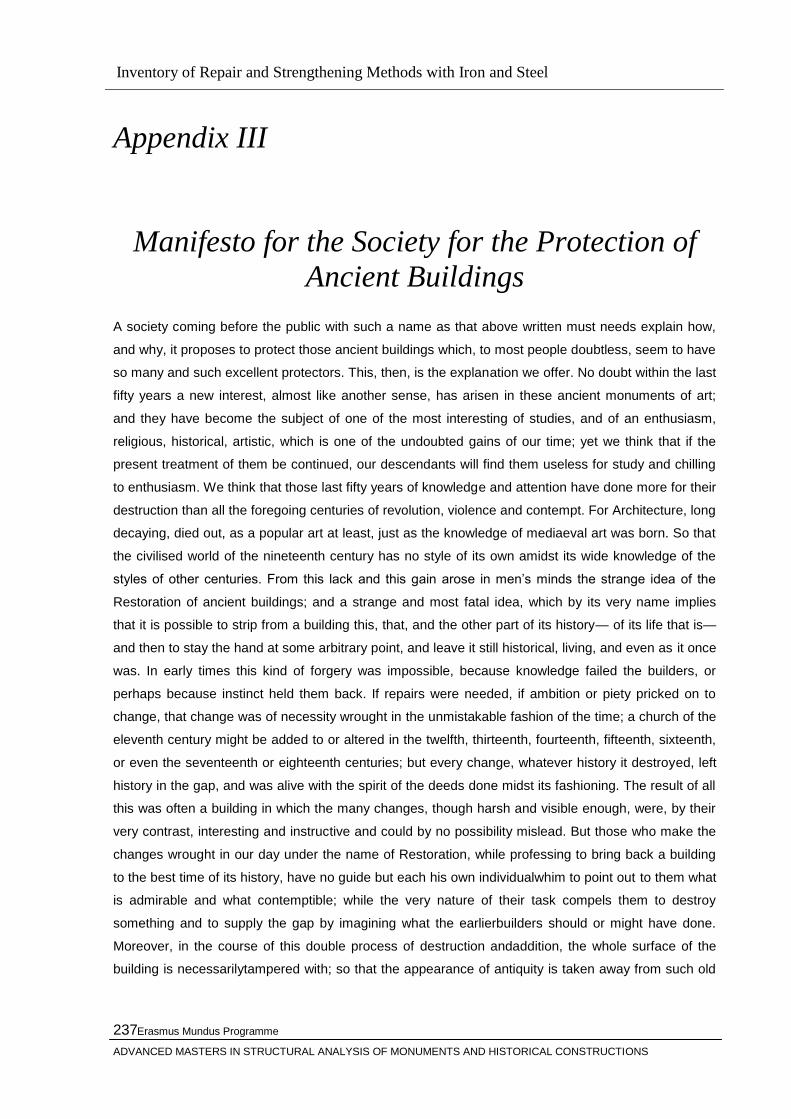
Inventory of Repair and Strengthening Methods with Iron and Steel
Erasmus Mundus Programme
ADVANCED MASTERS IN STRUCTURAL ANALYSIS OF MONUMENTS AND HISTORICAL CONSTRUCTIONS
237
Appendix III
Manifesto for the Society for the Protection of
Ancient Buildings
A society coming before the public with such a name as that above written must needs explain how,
and why, it proposes to protect those ancient buildings which, to most people doubtless, seem to have
so many and such excellent protectors. This, then, is the explanation we offer. No doubt within the last
fifty years a new interest, almost like another sense, has arisen in these ancient monuments of art;
and they have become the subject of one of the most interesting of studies, and of an enthusiasm,
religious, historical, artistic, which is one of the undoubted gains of our time; yet we think that if the
present treatment of them be continued, our descendants will find them useless for study and chilling
to enthusiasm. We think that those last fifty years of knowledge and attention have done more for their
destruction than all the foregoing centuries of revolution, violence and contempt. For Architecture, long
decaying, died out, as a popular art at least, just as the knowledge of mediaeval art was born. So that
the civilised world of the nineteenth century has no style of its own amidst its wide knowledge of the
styles of other centuries. From this lack and this gain arose in men‘s minds the strange idea of the
Restoration of ancient buildings; and a strange and most fatal idea, which by its very name implies
that it is possible to strip from a building this, that, and the other part of its history— of its life that is—
and then to stay the hand at some arbitrary point, and leave it still historical, living, and even as it once
was. In early times this kind of forgery was impossible, because knowledge failed the builders, or
perhaps because instinct held them back. If repairs were needed, if ambition or piety pricked on to
change, that change was of necessity wrought in the unmistakable fashion of the time; a church of the
eleventh century might be added to or altered in the twelfth, thirteenth, fourteenth, fifteenth, sixteenth,
or even the seventeenth or eighteenth centuries; but every change, whatever history it destroyed, left
history in the gap, and was alive with the spirit of the deeds done midst its fashioning. The result of all
this was often a building in which the many changes, though harsh and visible enough, were, by their
very contrast, interesting and instructive and could by no possibility mislead. But those who make the
changes wrought in our day under the name of Restoration, while professing to bring back a building
to the best time of its history, have no guide but each his own individualwhim to point out to them what
is admirable and what contemptible; while the very nature of their task compels them to destroy
something and to supply the gap by imagining what the earlierbuilders should or might have done.
Moreover, in the course of this double process of destruction andaddition, the whole surface of the
building is necessarilytampered with; so that the appearance of antiquity is taken away from such old

Inventory of Repair and Strengthening Methods with Iron and Steel
Erasmus Mundus Programme
ADVANCED MASTERS IN STRUCTURAL ANALYSIS OF MONUMENTS AND HISTORICAL CONSTRUCTIONS
238
parts of the fabric as are left, and there is no laying to rest in the spectator the suspicion of what may
have been lost; and in short, a feeble and lifeless forgery is the final result of all the wasted labour.
It is sad to say, that in this manner most of the bigger Minsters, and a vast number of more humble
buildings, both in England and on the Continent, have been dealt with by men of talent often, and
worthy of better employment, but deaf to the claims of poetry and history in the highest sense of the
words. For what is left we plead before our architects themselves, before the official guardians of
buildings, and before the public generally, and we pray them to remember how much is gone of the
religion, thought and manners of time past, never by almost universal consent, to be Restored; and to
consider whether it be possible to Restore those buildings, the living spirit of which, it cannot be too
often repeated, was an inseparable part of that religion and thought, and those past manners. For our
part we assure them fearlessly, that of all the Restorations yet undertaken, the worst have meant the
reckless stripping a building of some of its most interesting material features; whilst the best have their
exact analogy in the Restoration of an old picture, where the partly-perished work of the ancient
craftsmaster has been made neat and smooth by the tricky hand of some unoriginal and thoughtless
hack of today. If, for the rest, it be asked us to specify what kind of amount of art, style, or other
interest in a building makes it worth protecting, we answer, anything which can be looked on as
artistic, picturesque, historical, antique, or substantial: any work, in short, over which educated, artistic
people would think it worth while to argue at all. It is for all these buildings, therefore, of all times and
styles, that we plead, and call upon those who have to deal with them, to put Protection in the place of
Restoration, to stave off decay by daily care, to prop a perilous wall or mend a leaky roof by such
means as are obviously meant for support or covering, and show no pretence of other art, and
otherwise to resist all tampering with either the fabric or ornament of the building as it stands; if it has
become inconvenient for its present use, to raise another building rather than alter or enlarge the old one; infine
to treat our ancient buildings as monuments of a bygone art, created by bygone manners, that modern art cannot
meddle with without destroying. Thus, and thus only, shall we escape the reproach of our learning being turned
into a snare to us; thus, and thus only can we protect ourancient buildings, and hand them down instructive and
venerable to those that come after us.
(Written by William Morris, 1877)
Appendix IV

Inventory of Repair and Strengthening Methods with Iron and Steel
Erasmus Mundus Programme
ADVANCED MASTERS IN STRUCTURAL ANALYSIS OF MONUMENTS AND HISTORICAL CONSTRUCTIONS
239
ICOMOS Charters
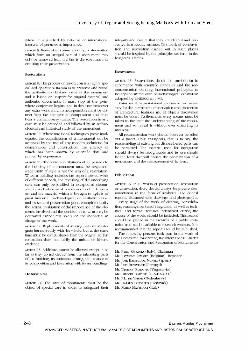
Inventory of Repair and Strengthening Methods with Iron and Steel
Erasmus Mundus Programme
ADVANCED MASTERS IN STRUCTURAL ANALYSIS OF MONUMENTS AND HISTORICAL CONSTRUCTIONS
240

Inventory of Repair and Strengthening Methods with Iron and Steel
Erasmus Mundus Programme
ADVANCED MASTERS IN STRUCTURAL ANALYSIS OF MONUMENTS AND HISTORICAL CONSTRUCTIONS
241
Appendix V