introduction - gpchopta.ac.ingpchopta.ac.in/wp-content/uploads/2019/02/rbt_6th-ce-e-notes.docx ·...
TRANSCRIPT
* Under revision
LECTURE e-
NotesRailways , Bridge &
Tunnels
CDL Govt. Polytechnic NathsariChopta
Vikram Singh
Lecturer in Civil Engineering

IntroductionLecture-1 History of IndianRailways
In the year 1832 the first Railway running on steam engine, was launched in England.
Thereafter on 1st of August, 1849 the Great Indian Peninsular Railways Company was
established in India. On 17th of August 1849, a contract was signed between the Great Indian
Peninsular Railways Company and East India Company. As a result of the contract an
experiment was made by laying a railway track between Bombay and Thane (56Kms).
On 16th April, 1853, the first train service was started from Bombay toThane.
On 15th August, 1854, the 2nd train service commenced between Howrah andHubli.
On the 1st July, 1856, the 3rd train service in India and first in South India commenced
between Vyasarpadi and Walajah Road and on the same day the section between
Vyasarpadi and Royapuram by Madras Railway Company was alsoopened.
Subsequently construction of this efficient transport system began simultaneously in different
parts of the Country. By the end of 19th Century 24752 Kms. of rail track was laid for traffic. At
this juncture the power, capital, revenue rested with the British. Revenue started flowing through
passenger as well as through goods traffic.
Organizational structure
Railway zones
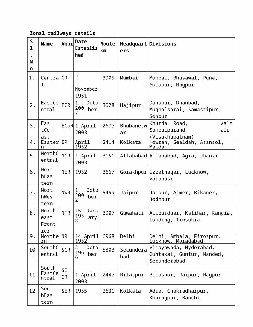
Indian Railways is divided into several zones, which are further sub-divided into divisions. The
number of zones in Indian Railways increased from six to eight in 1951, nine in 1952 and sixteen
in 2003. Each zonal railway is made up of a certain number of divisions, each having a divisional
headquarters. There are a total of sixty-eight divisions. Each of the sixteen zones is headed by a
general manager who reports directly to the Railway Board. The zones are further divided into
divisions under the control of divisional railway managers (DRM).

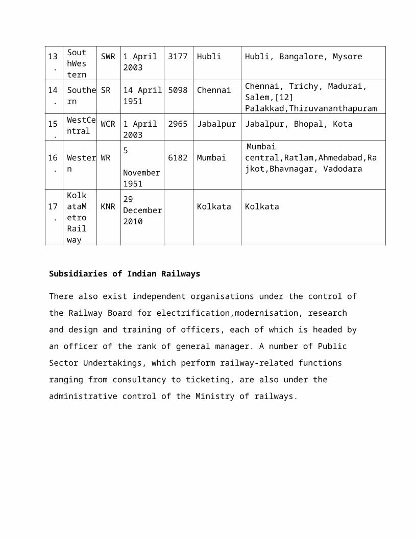
Zonal railways detailsSl. No
Name Abbr Date Established
Routekm
Headquarters
Divisions
1. Central CR 5
November 1951
3905 Mumbai Mumbai, Bhusawal, Pune, Solapur, Nagpur
2. EastCentral
ECR 12002
October
3628 Hajipur Danapur, Dhanbad, Mughalsarai, Samastipur, Sonpur
3. EastCoast
ECoR 1 April 2003
2677 Bhubaneswar
Khurda Road, Sambalpurand (Visakhapatnam)
Waltair
4. Eastern ER April 1952 2414 Kolkata Howrah, Sealdah, Asansol, Malda
5. NorthCentral
NCR 1 April 2003
3151 Allahabad Allahabad, Agra, Jhansi
6. NorthEastern
NER 1952 3667 Gorakhpur Izzatnagar, Lucknow, Varanasi
7. NorthWestern
NWR 12002
October
5459 Jaipur Jaipur, Ajmer, Bikaner, Jodhpur
8. Northeast Frontier
NFR 151958
January
3907 Guwahati Alipurduar, Katihar, Rangia, Lumding, Tinsukia
9. Northern NR 14 April 1952
6968 Delhi Delhi, Ambala, Firozpur, Lucknow, Moradabad
10. SouthCentral
SCR 21966
October
5803 Secunderabad
Vijayawada, Hyderabad, Guntakal, Guntur, Nanded, Secunderabad
11.SouthEastCentral
SECR 1 April
20032447 Bilaspur Bilaspur, Raipur, Nagpur
12. SouthEastern
SER 1955 2631 Kolkata Adra, Chakradharpur, Kharagpur, Ranchi
13. SouthWestern
SWR 1 April 2003
3177 Hubli Hubli, Bangalore, Mysore
14. Southern SR 14 April 1951
5098 Chennai Chennai, Trichy, Madurai, Salem,[12] Palakkad,Thiruvananthapuram
15. WestCentral
WCR 1 April 2003
2965 Jabalpur Jabalpur, Bhopal, Kota
16. Western WR5
6182 MumbaiMumbaicentral
November 1951
,Ratlam,Ahmedabad,Rajkot,Bhavnagar, Vadodara
17.KolkataMetroRailway
KNR29 December 2010
Kolkata Kolkata
Subsidiaries of Indian Railways
There also exist independent organisations under the control of the Railway Board for
electrification,modernisation, research and design and training of officers, each of which is
headed by an officer of the rank of general manager. A number of Public Sector Undertakings,
which perform railway-related functions ranging from consultancy to ticketing, are also under
the administrative control of the Ministry of railways.
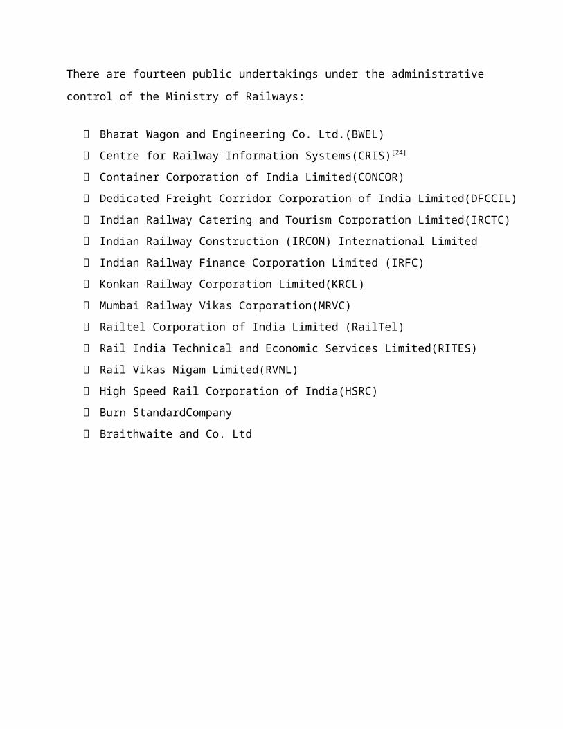
There are fourteen public undertakings under the administrative control of the Ministry of
Railways:
Bharat Wagon and Engineering Co. Ltd.(BWEL)
Centre for Railway Information Systems(CRIS)[24]
Container Corporation of India Limited(CONCOR)
Dedicated Freight Corridor Corporation of India Limited(DFCCIL)
Indian Railway Catering and Tourism Corporation Limited(IRCTC)
Indian Railway Construction (IRCON) International Limited
Indian Railway Finance Corporation Limited (IRFC)
Konkan Railway Corporation Limited(KRCL)
Mumbai Railway Vikas Corporation(MRVC)
Railtel Corporation of India Limited (RailTel)
Rail India Technical and Economic Services Limited(RITES)
Rail Vikas Nigam Limited(RVNL)
High Speed Rail Corporation of India(HSRC)
Burn StandardCompany
Braithwaite and Co. Ltd
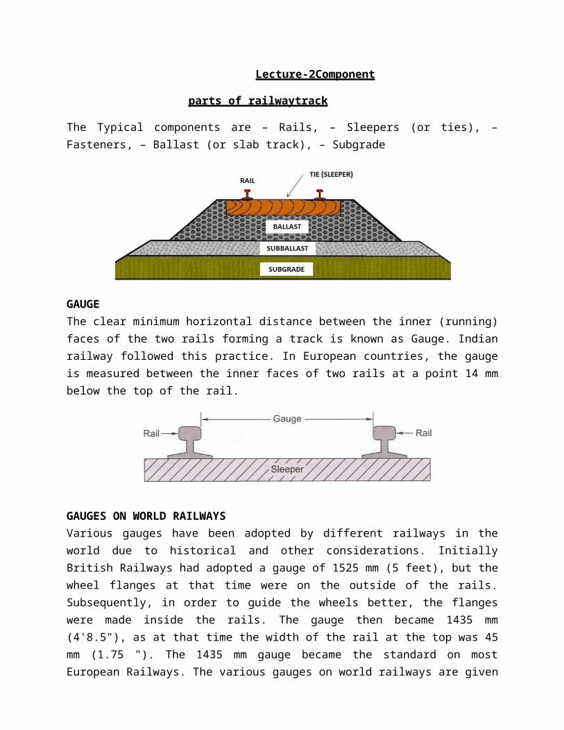
Lecture-2Component
parts of railwaytrack
The Typical components are – Rails, – Sleepers (or ties), – Fasteners, – Ballast (or slab track), – Subgrade
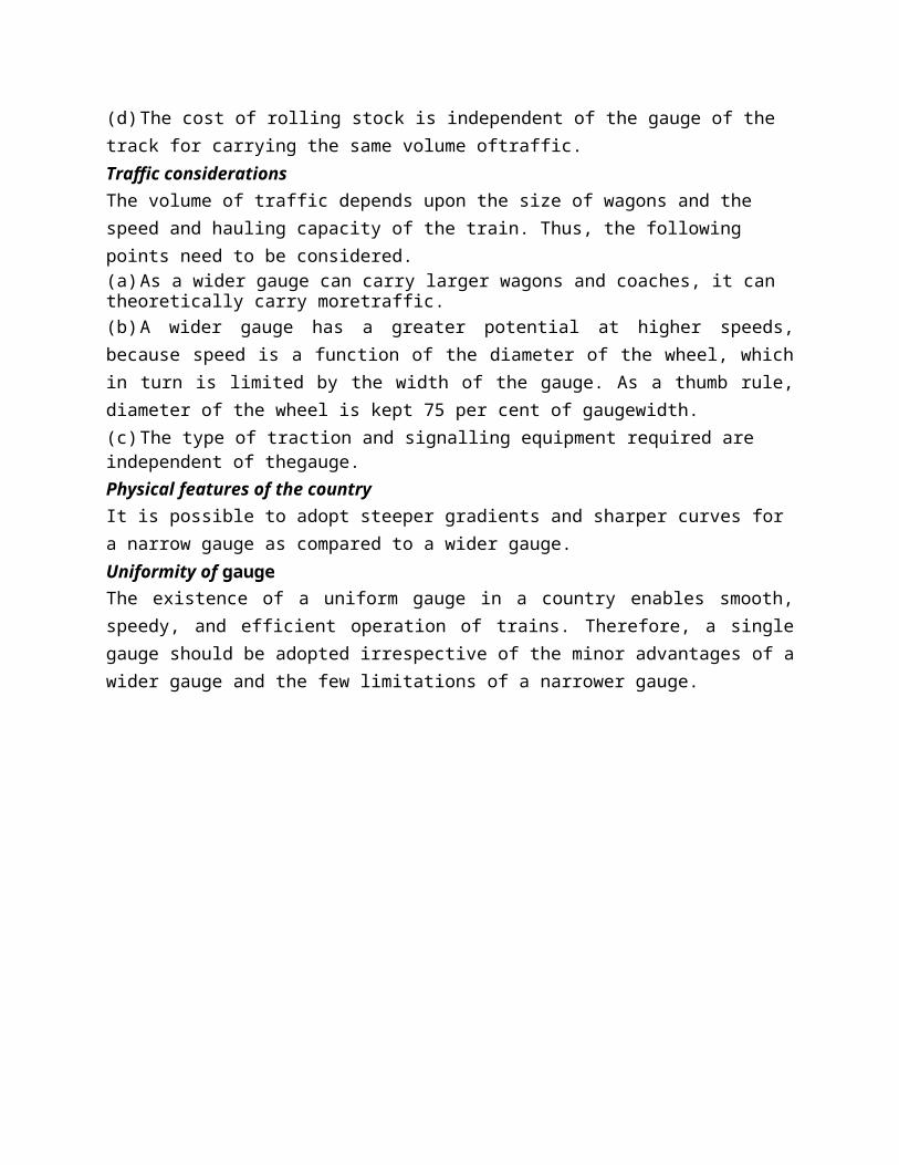
GAUGEThe clear minimum horizontal distance between the inner (running) faces of the two rails forming a track is known as Gauge. Indian railway followed this practice. In European countries, the gauge is measured between the inner faces of two rails at a point 14 mm below the top of the rail.
GAUGES ON WORLD RAILWAYSVarious gauges have been adopted by different railways in the world due to historical and other considerations. Initially British Railways had adopted a gauge of 1525 mm (5 feet), but the wheel flanges at that time were on the outside of the rails. Subsequently, in order to guide the wheels better, the flanges were made inside the rails. The gauge then became 1435 mm (4'8.5"), as at that time the width of the rail at the top was 45 mm (1.75 "). The 1435 mm gauge became the standard on most European Railways. The various gauges on world railways are given in Table2.1.
Various gauges on world railwaysType of gauge Gauge
(mm)Gauge(feet)
% of totallength
Countries
Standard gauge 1435 4'8.5" 62 England, USA, Canada, Turkey, Persia, andChina
Broad gauge 1676 5 '6" 6 India, Pakistan, Sri Lanka,Brazil,
ArgentinaBroad gauge 1524 5'0" 9 Russia, FinlandCape gauge 1067 3 '6" 8 Africa, Japan, Java, Australia, and New
ZealandMetre gauge 1000 3 '3.5" 9 India, France, Switzerland, and
Argentina23 various
othergauges
Differentgauges
Differentgauges
6 Various countries
DIFFERENT GAUGES ON INDIAN RAILWAYSThe East India Company intended to adopt the standard gauge of 1435 mm in India also. This proposal was, however, challenged by W. Simms, Consulting Engineer to the Government of India, who recommended a wider gauge of 1676 mm (5 '6 "). The Court of Directors of the East India Company decided to adopt Simms's recommendation and 5'6 " finally became the Indian standard gauge. In 1871, the Government of India wanted to construct cheaper railways for the development of the country and 1000 mm metre gauge was introduced. In due course of time, two more gauges of widths 762 mm (2 '6 ") and 610 mm (2 '0 ") were introduced for thinly populated areas, mountain railways, and other miscellaneous purposes. The details of the various gauges existing on Indian Railways are given in Tablebelow.
Various gauges on Indian Railways as on 31.03.2011Name of gauge Width (mm) Route (km) % of route (km)Broad gauge (BG) 1676 55,188 85.6Metre gauge (MG) 1000 6809 10.6Narrow gauge (NG) 762 2463 3.8
610Total all gauges 64,460 100
Broad Gauge: - When the clear horizontal distance between the inner faces of two parallel rails forming a track is 1676mm the gauge is called Broad Gauge (B.G)This gauge is also known as standard gauge of India and is the broadest gauge of the world.The Other countries using the Broad Gauge are Pakistan, Bangladesh, SriLanka, Brazil, Argentine, etc.50% India‘s railway tracks have been laid to this gauge.

Suitability: - Broad gauge is suitable under the following Conditions:-(i) When sufficient funds are available for the railwayproject.(ii) When the prospects of revenue are verybright.This gauge is, therefore, used for tracks in plain areas which are densely populated i.e. for routes of maximum traffic, intensities and at places which are centers of industry and commerce.2. Metre Gauge: - When the clear horizontal distance between the inner faces of two parallel rails forming a track is 1000mm, the gauge is known as Metre Gauge (M.G) The other countries using Metre gauge are France, Switzerland, Argentine, etc. 40% of India‘s railway tracks have been laid to thisgauge.Suitability:- Metre Gauge is suitable under the following conditions:-(i) When the funds available for the railway project areinadequate.(ii) When the prospects of revenue are not verybright.This gauge is, therefore, used for tracks in under-developed areas and in interior areas, where traffic intensity is small and prospects for future development are not very bright.3. Narrow Gauge:- When the clear horizontal distance between the inner faces of two parallel rails forming a track is either 762mm or 610mm, the gauge is known as Narrow gauge (N.G) The other countries using narrow gauge are Britain, South Africa, etc. 10% of India‘s railway tracks have been laid to thisgauge.Suitability: - Narrow gauge is suitable under the following conditions:-(i) When the construction of a track with wider gauge is prohibited due to the provision of sharp curves, steep gradients, narrow bridges and tunnels etc.(ii) When the prospects of revenue are not very bright. This gauge is, therefore, used in hilly and very thinly populated areas. The feeder gauge is commonly used for feeding raw materials to big government manufacturing concerns as well as to private factories such as steel plants, oil refineries, sugar factories,etc.
CHOICE OF GAUGEThe choice of gauge is very limited, as each country has a fixed gauge and all new railway lines are constructed to adhere to the standard gauge. However, the following factors theoretically influence the choice of the gauge:Cost considerationsThere is only a marginal increase in the cost of the track if a wider gauge is adopted. In this connection, the following points are important(a) There is a proportional increase in the cost of acquisition of land, earthwork, rails, sleepers, ballast, and other track items when constructing a widergauge.(b) The cost of building bridges, culverts, and runnels increases only marginally due to a wider gauge.(c) The cost of constructing station buildings, platforms, staff quarters, level crossings, signals, etc., associated with the railway network is more or less the same for allgauges.

(d) The cost of rolling stock is independent of the gauge of the track for carrying the same volume oftraffic.Traffic considerationsThe volume of traffic depends upon the size of wagons and the speed and hauling capacity of the train. Thus, the following points need to be considered.(a) As a wider gauge can carry larger wagons and coaches, it can theoretically carry moretraffic.(b) A wider gauge has a greater potential at higher speeds, because speed is a function of the diameter of the wheel, which in turn is limited by the width of the gauge. As a thumb rule, diameter of the wheel is kept 75 per cent of gaugewidth.(c) The type of traction and signalling equipment required are independent of thegauge.Physical features of the countryIt is possible to adopt steeper gradients and sharper curves for a narrow gauge as compared to a wider gauge.Uniformity of gaugeThe existence of a uniform gauge in a country enables smooth, speedy, and efficient operation of trains. Therefore, a single gauge should be adopted irrespective of the minor advantages of a wider gauge and the few limitations of a narrower gauge.

Introduction
Lecture-3
PROBLEMS OF MULTI GAUGE SYSTEM
The need for uniformity of gauge has been recognized by all the advanced countries of the
world. A number of problems have cropped up in the operation of the Indian Railways because
of the multi-gauge system (use of three gauges). The ill effects of change of gauge (more
popularly known as break of gauge) are numerous; some of these are enumeratedhere.
Inconvenience to passengers
Due to change of gauge, passengers have to change trains mid-journey along with their luggage,
which causes inconvenience such as the following:
(a) Climbing stairs and crossingbridges
(b) Getting seats in the compartments of the latertrains
(c) Missing connections with the later trains in case the earlier train islate
(d) Harassment caused byporters
(e) Transporting luggage from one platform toanother.
Difficulty in trans-shipment of goods
Goods have to be trans-shipped at the point where the change of gauge takes place. This causes
the following problems:
(a) Damage to goods duringtrans-shipment
(b) Considerable delay in receipt of goods at thedestination
(c) Theft or misplacement of goods during trans-shipment and the subsequentclaims
(d) Non-availability of adequate and specialized trans-shipment labour and staff, particularly
duringstrikes
Inefficient use of rolling stock
As wagons have to move empty in the direction of the trans-shipment point, they are not fully
utilized. Similarly, idle wagons or engines of one gauge cannot be moved on another gauge.
Hindrance to fast movement of goods and passenger traffic
Due to change in the gauge, traffic cannot move fast which becomes a major problem
particularly during emergencies such as war, floods, andaccidents.

Additional facilities at stations and yards
Costly sheds and additional facilities need to be provided for handling the large volume of goods
at trans-shipment points. Further, duplicate equipment and facilities such as yards and platforms
need to be provided for both gauges at trans-shipment points.
Difficulties in balanced economic growth
The difference in gauge also leads to unbalanced economic growth. This happens because
industries set up near MG/NG stations cannot send their goods economically and efficiently to
areas being served by BG stations.
Difficulties in future gauge conversion projects
Gauge conversion is quite difficult, as it requires enormous effort to widen existing tracks.
Widening the gauge involves heavy civil engineering work such as widening of the embankment,
bridges and tunnels, as well as tracks; additionally, a wider rolling stock is also required. During
the gauge conversion period, there are operational problems as well, since the traffic has to be
slowed down and even suspended for a certain period in order to execute the work.
UNI-GAUGE POLICY OF INDIAN RAILWAYS
The problems caused by a multi-gauge system in a country have been discussed in the previous
section. The multi-gauge system is not only costly and cumbersome but also causes serious
bottlenecks in the operation of the Railways and hinders the balanced development of the
country. Indian Railways therefore took the bold decision in 1992 of getting rid of the multi-
gauge system and following the uni-gauge policy of adopting the broad gauge (1676 mm)
uniformly.
Benefits of Adopting BG (1676 mm) as the UniformGauge
The uni-gauge system will be highly beneficial to rail users, the railway administration, as well
as to the nation. Following are the advantages of auni-system:
No transport bottlenecks
There will be no transport bottlenecks after a uniform gauge is adopted and this will lead to
improved operational efficiency resulting in fast movement of goods and passengers.
No trans-shipment hazards

There will be no hazards of trans-shipment and as such no delays, no damage to goods, no
inconvenience to passengers of transfer from one train to another train.
Provisions of alternate routes
Through a uni-gauge policy, alternate routes will be available for free movement of traffic and
there will be less pressure on the existing BG network. This is expected to result in long-haul
road traffic reverting to the railways.
Better turnaround
There will be a better turnaround of wagons and locomotives, and their usage will improve the
operating ratio of the railway system as a whole. As a result the community will be benefited
immensely.
Improved utilization of track
There will be improved utilization of tracks and reduction in the operating expenses of the
railway.
Balanced economic growth
The areas currently served by the MG will receive an additional fillip, leading to the removal of
regional disparities and balancing economic growth.
No multiple tracking works
The uni-gauge project will eliminate the need for certain traffic facilities and multiple tracking
works, which will offset the cost of gauge conversions to a certain extent.
Better transport infrastructure
Some of the areas served by the MG have the potential of becoming highly industrialized; skilled
manpower is also available. The uni-gauge policy will help in providing these areas a better
transportation infrastructure.
Boosting investor's confidence
With the liberalization of the economic policy, the uni-gauge projects of Indian Railways have
come to play a significant role. This will help in boosting the investors' confidence that their
goods will be distributed throughout the country in time and without any hindrance. This will
also help in setting up industries in areas not yet exploited because of the lack of infrastructure
facilities.
Planning of Uni-gauge Projects
The gauge-conversion programme has been accelerated on Indian Railways since 1992. In the
eighth Plan (1993-97) itself, the progress achieved in gauge-conversion projects in five years was
more than the total progress made in the past 45 years. The progress of gauge-conversion
projects is briefly given in Tablebelow.
Progress of gauge-conversion projects
Year Progress in gauge conversion (kms) Remarks
1947-1992 2500 Approx. figure
1993-1997 6897 Actual
1998-2004 3787 Actual
2005-2011 6564 Actual
The current position is that the gauge-conversion project still pending on Indian Railways is
8855 kms which is likely to be completed in next five years. Execution of a gauge conversion
project is quite a tricky job and lot of planning is to be done for thesame.

Lecture-4
WHEEL AND AXIS ARRANGEMENTS AND CONING OF WHEELS
Introduction
Wheels and axles we have the different types of the locomotives under wagons which are used
for the hauling of the passengers and freight. All these wagons and locomotives have different
specifications depending on the gauges for which they have been used. If you look at the various
locomotives from the very starting of our history, we have been using steam locomotives and
then they have been replaced by diesel locomotives and finally by the electric locomotives.
In the case of the steam locomotives, the wheels and axles are classified by on the basis of Whyte
system. Traditionally, steam locomotives have been classified using either their wheel arrangements
or sometimes they are also been classified on the basis of axle arrangements.
In the case of the wheel arrangements classification, they are being classified on the basis of Whyte
system and other system locomotives have three different types of wheel basis. They have the wheel
basis which are either coupled or which are having the driving conditions or detective power attached
to them or the wheel basis on which no attractive power is attached.
In Indian practice, the Indian practice has been taken from the United Kingdom because British were
the persons who introduced the Indian railways in our country and in this system we count wheels
and we do not count the axles as far as the steam locomotives are concerned. In the case of steam
locomotives, one examples is been taken here where it is been shown as 2-4-2. Now this 2-4-2 has
the significance in terms of the wheel basis as been defined earlier. The first 2 is the front wheels or
the 2 number of wheels have been placed or what we can say is that there is one axle which is being
placed in the front condition. Then the 4 part is to the 4 number of wheels which have been placed in
the central condition where they are the powered wheels or the driving wheels and therefore they
transforms into the 2 axles condition and then there are trailing wheels where we have 2 wheels at the
back and again, if it transform them into the actual condition, it will be working to oneaxle.
The compound locomotive is a condition where there is a more attractive power which is required to
haul the passenger or the freight. The heavy amount of the freight which is to be transported and the
trailing conditions governs the conditions where we require to provide two locomotives together so
as to haul them. Here, this is an example of compound locomotive where two locomotiveof

condition 2-8-2 or 2-8-4 have been joined together so as to haul the traffic or the passengers or the
freight. Again, if we go by the Whyte condition, Whyte system of classification of the locomotives of
the wheel configuration then 2-8-2 means they have 2 front wheels, 8 medium or central wheels and
2 trailer wheels, in case of the first locomotives whereas in the case of the second locomotives we
have 2 front wheels, 8 central condition wheels which are electrically driven, which are driven for the
movement of the locomotives and then in this case we have 4 trailingwheels.
Coning wheels has the following disadvantages:
1. In order to minimize the above below disadvantages the tilting of rails is done. i.e. the rails are
not laid flat but tilted inwards by using inclined base plates sloped at 1 in 20 which is also the
slope of coned surface ofwheels.
2. The pressure of the horizontal component near the inner edge of the rail has a tendency to
wear the railquickly.
3. The horizontal components tend to turn the rail outwardly and hence the gauge is widened
sometimes.
4. If no base plates are provided, sleepers under the outer edge of the rails aredamaged.
5. In order to minimize the above mentioned disadvantages the tilting of rails is done. i.e. the
rails are not laid flat but tilted inwards by using inclined base plates sloped at 1 in 20 which is
also the slope of coned surface ofwheels.
Advantages of Tilting of Rails
1. It maintains the gaugeproperly.
2. The wear at the head of rail isuniform.
3. It increases the life of sleepers and the rails.

Lecture-5
VARIOUS RESISTANCES AND THEIR EVALUATION
Introduction
Various forces offer resistance to the movement of a train on the track. These resistances may be
the result of movement of the various parts of the locomotives as well as the friction between
them, the irregularities in the track profile, or the atmospheric resistance to a train moving at
great speed. The tractive power of a locomotive should be adequate enough to overcome these
resistances and haul the train at a specifiedspeed.
RESISTANCE DUE TO FRICTION
Resistance due to friction is the resistance offered by the friction between the internal parts of
locomotives and wagons as well as between the metal surface of the rail and the wheel to a train
moving at a constant speed. This resistance is independent of speed and can be further broken
down into the following parts.
Journal friction This is dependent on the type of bearing, the lubricant used, the temperature
and condition of the bearing, etc. In the case of roll bearings, it varies from 0.5 to 1.0 kg per
tonne.
Internal resistance This resistance is consequential to the movement of the various parts of the
locomotive and wagons.
Rolling resistance This occurs due to rail-wheel interaction on account of the movement ofsteel
wheels on a steel rail. The total frictional resistance is given by the empiricalformula
R1= 0.0016 W
Where R1is the frictional resistance independent of speed and W is the weight of the train in
tonnes.
RESISTANCE DUE TO WAVE ACTION
When a train moves with speed a certain resistance develops due to the wave action in the rail.
Similarly, track irregularities such as longitudinal unevenness and differences in cross levels also
offer resistance to a moving train. Such resistances are different for different speeds. There is no
method for the precise calculation of these resistances but the following formula has been
evolved based on experience:
R2 = 0.00008 WV
Where R2is the resistance (in tonnes) due to wave action and track irregularities on account of
the speed of the train, W is the weight of the train in tonnes, and V is the speed of the train in
kmph.
RESISTANCE DUE TO WIND
When a vehicle moves with speed, a certain resistance develops, as the vehicle has to move
forward against the wind. Wind resistance consists of side resistance, head resistance, and tail
resistance, but its exact magnitude depends upon the size and shape of the vehicle, its speed, and
the wind direction as well as its velocity. Wind resistance depends upon the exposed area of the
vehicle and the velocity and direction of the wind. In Fig. below, V is the velocity of wind at an
angle θ. The horizontal component of wind, V cosθ, opposes the movement of the train. Wind
normally exerts maximum pressure when it acts at an angle of 60° to the direction of movement
of the train.
Wind resistance can be obtained by the following formula:
R3=0.000017AV2
Where A is the exposed area of vehicle (m2) and V is the velocity of wind (kmph).
R3= 0.0000006 W V2
Where R3is the wind resistance in tonnes, Vis the velocity of the train in km per hour, and W is
the weight of the train in tonnes.

RESISTANCE DUE TO GRADIENT
When a train moves on a rising gradient, it requires extra effort in order to move against gravity
as shown in Fig. below.
Assuming that a wheel of weight W is moving on a rising gradient OA, the following forces act
on the wheel.
(a) Weight of the wheel (W), which actsdownward
(b) Normal pressure N on the rail, which acts perpendicular to OA
(c) Resistance due to rising gradient (R4), which acts parallel toOA
These three forces meet at a common point Q and the triangle QCD can be taken as a triangle of
forces. It can also be geometrically proved that the two triangles QCD and AOB are similar.
RESISTANCE DUE TO CURVATURE
When a train negotiates a horizontal curve, extra effort is required to overcome the resistance
offered by the curvature of the track. Curve resistance is caused basically because of the
following reasons (Fig. below):
(a) The vehicle cannot adapt itself to a curved track because of its rigid wheel base. This is why
the frame takes up a tangential position as the vehicle tries to move in a longitudinal direction
along the curve as shown in Fig. below. On account of this, the flange of the outer wheel of the
leading axle rubs against the inner face of the outer rail, giving rise to resistance to the movement
of thetrain.

(b) Curve resistance can sometimes be the result of longitudinal slip, which causes the forward
motion of the wheels on a curved track. The outer wheel flange of the trailing axle remains clear
and tends to derail. The position worsens further if the wheel base is long and the curve issharp.
(c) Curve resistance is caused when a transverse slip occurs, which increases the friction between
the wheel flanges and therails.
(d) Poor track maintenance, particularly bad alignment, worn-out rails, and improper levels, also
increaseresistance.
(e) Inadequate superelevation increases the pressure on the outer rail and, similarly, excess
superelevation puts greater pressure on the inner rails, and this also contributes to an increase in
resistance.
The value of curve resistance can be determined by the following equation:
Curve resistance = C x (FG/R)
whereF is the force of sliding friction, G is the gauge of the track, R is the mean radius of the
curve, and C is the constant, which is dependent on various factors. This equation indicates that
(a) curve resistance increases with increase in gauge widthand
(b) resistance is inversely proportional to the radius, i.e., it increases with an increase inthe
degree of thecurve.
Empirical formulae have been worked out for curve resistance, which are as follows:
Curve resistance for BG (R5) = 0.0004 WD
Curve resistance for MG (R5) = 0.0003 WD
Curve resistance for NG (R5) = 0.0002 WD

Compensated gradient for curvature
Curve resistance is quite often compensated or offset by a reduction in the gradient. In this way,
the effect of curve resistance is translated in terms of resistance due to gradient. The
compensation is 0.04 per cent on BG, 0.03 per cent on MG, and 0.02 per cent on NG lines for
every 1° of the curve. This will be clear through the solved example given below.
RESISTANCE DUE TO STARTING AND ACCELERATING
Trains face these resistances at stations when they start, accelerate, and decelerate. The values of
these resistances are as follows:
Resistance on starting, R6 = 0.15 W1 + 0.005 W2
Resistance due to acceleration, R7 = 0.028 aW
whereW 1 is the weight of the locomotive in tonnes, W2is the weight of the trailing vehicles in
tonnes, W is the total weight of the locomotive and vehicle in tonnes. i.e. W1 + W2, and a is the
acceleration, which can be calculated by finding the increase in velocity per unit time, i.e., (V2 –
V1)/t, where V2is the final velocity. V1is the initial velocity, and t is the time taken.
Table below summarizes the various resistances faced by a train.

Introduction
Lecture-6
HAULING CAPACITY AND TRACTIVE EFFORT
The tractive effort of a locomotive is the force that the locomotive can generate for hauling the
load. The tractive effort of a locomotive should be enough for it to haul a train at the maximum
permissible speed. There are various tractive effort. Curves available for different locomotives
for different speeds, which enable the computation of the value of tractive effort. Tractive effort
is generally equal to or a little greater than the hauling capacity of the locomotive. If the tractive
effort:-much greater than what is required to haul the train, the wheels of the locomotive may
slip.
A rough assessment of the tractive effort of different types of locomotive.-provided in the
following sections.
Steam Locomotive
The tractive effort of a steam locomotive can be calculated by equating the total power generated
by the steam engine to the work done by the driving wheels.
Assume P to be the difference in steam pressure between the two sides of the inder, A the area of
the piston of the engine, a' the diameter of the piston of the ;ine, L the length of the stroke of the
engine, D the diameter of the wheel of locomotive, and Te the mean tractive effort of the
locomotive. Work done by /o-cylinder steam engine
= 2 X difference in steam pressure X area of the piston x 2 X length of the stroke = 2P x A x 2L
= 2P x (πd2/4)x 2L = πd2L
work done in one revolution of the driving wheel of the locomotive:
= tractive effort x circumference of the wheel
= Tc π D
squaring above two equations, πd2L = Tc π D
Tc =d2L/D
is clear from above Equation that tractive effort increases with an increase in n pressure
difference and the diameter and length of the piston, but decreases an increase in the diameter of
the driving wheel of the locomotive.

Diesel Locomotive
Tractive effort of a diesel-elective locomotive can be assessed by the following empirical
formula.
Te = (308 x RHP) / V
whereTe is the tractive effort of a diesel-electric locomotive, RHP is the rated horsepower of the
engine, and V is the velocity in km per hour.
Electric Locomotive
Tractive effort of an electric locomotive varies inversely with the power of speed. The empirical
formulae for calculating the approximate value of tractive effort are as follows
For an dc electric locomotive: Te = a /V3
For an ac electric locomotive: Te = a /V5
wherea is a constant depending upon the various characteristics of the locomotive.
.HAULING POWER OF A LOCOMOTIVE
Hauling power of a locomotive depends upon the weight exerted on the driving s and the friction
between the driving wheel and the rail. The coefficient of friction depends upon the speed of the
locomotive and the condition of the rail surface. The higher the speed of the locomotive, the
lower will be the coefficient of friction, which is about 0.1 for high speeds and 0.2 for low
speeds. The condition of the rail surface, whether wet or dry, smooth or rough, etc., also plays an
important role in deciding the value of the coefficient of function. If the surface is very smooth,
the coefficient of friction will be very low.
Hauling power = number of pairs of driving wheels x weight exerted on each driving axle
X coefficient of friction
Thus, for a locomotive with three pairs of driving wheels, an axle load of 20 tonnes, and a
coefficient of friction equal to 0.2, the hauling power will be equal to 3 x 20 x 0.2 tonne, i.e., 12
tonnes.
Example :Calculate the maximum permissible load that a BG locomotive with three pairs of
driving wheels bearing an axle load of 22 tonnes each can pull on a straight level track at a speed
of 80 km/h. Also calculate the reduction in speed if the train has to run on a rising gradient of 1
in 200. What would be the further reduction in speed if the train has to negotiate a 4° curve on
the rising gradient? Assume the coefficient of friction to be 0.2.

Lecture-7
RAIL
Introduction
Rails are the members of the track laid in two parallel lines to provide an unchanging,
continuous, and level surface for the movement of trains. To be able to withstand stresses, they
are made of high-carbon steel. Standard rail sections, their specifications, and various types of
rail defects are discussed in this section.
FUNCTION OF RAILS
Rails are similar to steel girders. They perform the following functions in a track:
(a) Rails provide a continuous and level surface for the movement oftrains.
(b) They provide a pathway which is smooth and has very little friction. The friction between the
steel wheel and the steel rail is about one-fifth of the friction between the pneumatic tyre and a
metalledroad.
(c) They serve as a lateral guide for thewheels.
(d) They bear the stresses developed due to vertical loads transmitted to them through axles and
wheels of rolling stock as well as due to braking and thermalforces.
(e) They carry out the function of transmitting the load to a large area of the formation through
sleepers and theballast.
TYPES OF RAILS
DOUBLE HEADED RAIL BULL HEADED RAIL FLAT-FOOTED RAIL

REQUIREMENTS OF AN IDEAL RAIL SECTION
The requirements of an ideal rail section are as follows:
(a) The rail should have the most economical section consistent with strength, stiffness, and
durability.
(b) The centre of gravity of the rail section should preferably be very close to the mid-height of
the rail so that the maximum tensile and compressive stresses areequal.
(c) A rail primarily consists of a head, a web, and a foot, and there should be an economical and
balanced distribution of metal in its various components so that each of them can fulfill its
requirementsproperly.
The requirements, as well as the main considerations, for the design of these rail components are
as follows:
Head The head of the rail should have adequate depth to allow for vertical wear. The rail head
should also be sufficiently wide so that not only is a wider running surface available, but also the
rail has the desired lateral stiffness.
Web The web should be sufficiently thick so as to withstand the stresses arising due to the loads
bore by it, after allowing for normal corrosion.
Foot The foot should be of sufficient thickness to be able to withstand vertical and horizontal
forces after allowing for loss due to corrosion. The foot should be wide enough for stability
against overturning. The design of the foot should be such that it can be economically and
efficiently rolled.
Fishing angles These must ensure proper transmission of loads from the rails to the fish plates.
The fishing angles should be such that the tightening of the plate does not produce any excessive
stress on the web of the rail.
Height of the rail The height should be adequate so that the rail has sufficient vertical stiffness
and strength as a beam.
Weight of rails
Though the weights of a rail and its section depend upon various considerations, the heaviest
axle load that the rail has to carrvolavs the most important role. The following is the thumb rule
for denning the maximum axle load with relation to the railsection:
Maximum axle load = 560 x sectional weight of rail in Ibs per yard or kg per metre
• For rails of 90 Ibs peryard,
Maximum axle load = 560 x 90 Ibs = 50,400 Ibs or 22.5 tonnes
• For rails of 52 kg perm,
Maximum axle load = 560 x 52 kg = 29.12 tonnes
• For rail of 60 kg perm,
Max. axle load for 60 kg/m rail = 560 x 60 kg = 33.60 tonnes
Length of rails
Theoretically, the longer is the rail, the lesser would be the number of joints and fittings required
and the lesser the cost of construction and maintenance. Longer rails are economical and provide
smooth and comfortable rides. The length of a rail is, however, restricted due to the following
factors:
(a) Lack of facilities for transport of longer rails, particularly oncurves
(b) Difficulties in manufacturing very longrails
(c) Difficulties in acquiring bigger expansion joints for longrails
(d) Heavy internal thermal stresses in longrails
Taking the above factors into consideration, Indian Railways has standardized a rail length of 13
m (previously 42 ft) for broad gauge and 12 m (previously 39 ft) for MG and NG tracks. Indian
Railways is also planning to use 39 m, and even longer rails in its track system. Now 65 m/78 m
long rails are being produced at SAIL, Bhilai and it is planned to manufacture 130 m long rails.

Introduction
Lecture-
8SLEEPER
S
Sleepers are the transverse ties that are laid to support the rails. They have an important role in
the track as they transmit the wheel load from the rails to the ballast. Several types of sleepers
are used on Indian Railways. The characteristics of these sleepers and their suitability with
respect to load conditions are described in thissection.
FUNCTIONS AND REQUIREMENTS OF SLEEPERS
The main functions of sleepers are as follows:
(a) Holding the rails in their correct gauge andalignment
(b) Giving a firm and even support to therails
(c) Transferring the load evenly from the rails to a wider area of theballast
(d) Acting as an elastic medium between the rails and the ballast to absorb the blows and
vibrations caused by movingloads
e) Providing longitudinal and lateral stability to the permanent way
(f) Providing the means to rectify the track geometry during their service life
Apart from performing these functions the ideal sleeper should normally fulfill the following
requirements.
a) The initial as well as maintenance cost should beminimum.
b) The weight of the sleeper should be moderate so that it is convenient tohandle.
c) The designs of the sleeper and the fastenings should be such that it is possible to fix and
remove the railseasily.
d) The sleeper should have sufficient bearing area so that the ballast under it is notcrushed.
e) The sleeper should be such that it is possible to maintain and adjust the gaugeproperly
f) The material of the sleeper and its design should be such that it does not break or get damaged
duringpacking.
g) The design of the sleeper should be such that it is possible to have trackcircuiting.
h) The sleeper should be capable of resisting vibrations and shocks caused by the passage of fast
movingtrains,

i) The sleeper should have anti-sabotage and anti-theftfeatures.
SLEEPER DENSITY AND SPACING OF SLEEPERS
Sleeper density is the number of sleepers per rail length. It is specified as (M + x) or (N + x),
where M or N is the length of the rail in metres and x is a number that varies according to factors
such as
(a) axle load andspeed,
(b) type and section ofrails,
(c) type and strength of thesleepers,
(d) type of ballast and depth of ballast cushion, and
(e) nature offormation.
If the sleeper density is M+ 7 on a broad gauge route and the length of the rail is 13 m, it implies
that 13 + 7 = 20 sleepers will be used per rail length of the track on that route. The number of
sleepers in a track can also be specified by indicating the number of sleepers per kilometre of the
track, for example, 1540 sleepers/km. This specification becomes more relevant particularly in
cases where rails are welded and the length of the rail does not have much bearing on the number
of sleepers required. This system of specifying the number of sleepers per kilometre exists in
many foreign countries and is now being adopted on Indian Railways as well.
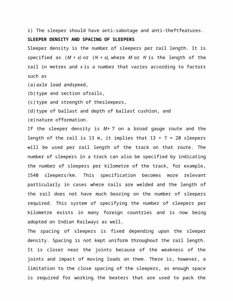
The spacing of sleepers is fixed depending upon the sleeper density. Spacing is not kept uniform
throughout the rail length. It is closer near the joints because of the weakness of the joints and
impact of moving loads on them. There is, however, a limitation to the close spacing of the
sleepers, as enough space is required for working the beaters that are used to pack the joint
sleepers. The standard spacing specifications adopted for a fish-plated-track on Indian Railways
are given in Table below. The notations used in this table are explained in Fig. below.

TYPES OF SLEEPERS
The sleepers mostly used on Indian Railways are
(i) woodensleepers,
(ii) cast iron (CI)sleepers,
(iii) steel sleepers,and
(iv) Concretesleepers.
Comparison of different types of sleepersCharacteristics Type of sleeper
Wooden Steel 'CI Concrete
Service life (years) 12-15 40-50 40-50 50-60
Weight of sleeper forBG (kg)
83 79 87 267
Handling Manual handling; no damage to sleeper while handling
Manual handling; no damage to sleeper whilehandling
Manual handling; liable to break by rough handling
No manual handling; gets damaged by rough handling
Type of maintenance Manualmechanized
or Manual or mechanized Manual Mechanized only
Cost of maintenance High Medium Medium LowGauge adjustment Difficult Easy Easy No
gauge possible
adjustment
Track circuiting Best Difficult; insulating pads arenecessary
Difficult; insulating pads arenecessary
Easy
Damage by white ants andcorrosion
Can be damaged by white ants
No damage by white ants but corrosion is possible
Can be damaged by corrosion
No damage by white ants or corrosion
Suitabilityfastening
for Suitable forand EFf
CF* Suitable for CF and EF Suitable for CF only Suitable for EF only
Track elasticity Good Good Good BestCreep Excessive Less Less MinimumScrap value Low Higher than wooden High None

Introduction
Lecture-9
BALLAST AND BALLAST REQUIREMENTS
Ballast is a layer of broken stones, gravel, rnoorum, or any other granular material placed and
packed below and around sleepers for distributing load from the sleepers to the formation. It
provides drainage as well as longitudinal and lateral stability to the track. Different types of
ballast materials and their specifications are discussed in this chapter.
FUNCTIONS OF BALLAST
The ballast serves the following functions in a railwaytrack.
• It provides a level and hard bed for the sleepers to reston.
• It holds the sleepers in position during the passage oftrains.
• It transfers and distributes load from the sleepers to a large area of theformation.
• It provides elasticity and resilience to the track for proper ridingcomfort.
• It provides the necessary resistance to the track for longitudinal and lateralstability.
• It provides effective drainage to thetrack.
• It provides an effective means of maintaining the level and alignment of thetrack.
TYPES OF BALLAST
The different types of ballast used on Indian Railways are described here.
Sand ballast
Sand ballast is used primarily for cast iron (CI) pots. It is also used with wooden ir.d steel trough
sleepers in areas where traffic densitv is verv low. Coarse sand is preferred in comparison to fine
sand. It has good drainage properties, but has the drawback of blowing off because of being
light. It also causes excessive wear of the rail top and the moving parts of the rollingstock.
Moorum ballast
The decomposition of laterite results in the formation of moorum. It is red, and sometimes
yellow, in colour. The moorum ballast is normally used as the initial ballast in new constructions
and also as sub-ballast. As it prevents water from percolating into the formation, it is also used as
a blanketing material for black cotton soil.
Coal ash or cinder
This type of ballast is normally used in yards and sidings or as the initial ballast in new
constructions since it is very cheap and easily available. It is harmful for steel sleepers and
fittings because of its corrosive action.
Broken stone ballast
This type of ballast is used the most on Indian Railways. Good stone ballast is generally
procured from hard stones such as granite, quartzite, and hard trap. The quality of stone should
be such that neither it should be porous nor it flake off due to the weathering. Good quality hard
stone is normally used for high-speed tracks. This type of ballast works out to be economical in
the longrun.
Other types of ballast
There are other types of ballast also such as the brickbat ballast, gravel ballast, kankar stone
ballast, and even earth ballast. These types of ballast are used only in special circumstances.
The comparative advantages, disadvantages, and suitability of different types of ballast are given
in Table below.
SIZES OF BALLAST
Previously, 50 mm (2") ballasts were specified for flat-bottom sleepers such as concrete and
wooden sleepers, and 40 mm (1.5") ballasts for metal sleepers such as CST-9 and trough
sleepers. Now, to ensure uniformity, 50 mm (2") ballasts have been adopted universally for all
types ofsleepers.
Points and crossings are subjected to heavy blows of moving loads and hence are maintained to a
higher degree of precision. A small sized, 25 mm (1") ballast: s. therefore, preferable because of
its fineness for slight adjustments, better compaction, and increased frictional area of the ballast.
For uniformity sake, the Indian Railways has adopted the same standard size of ballast for the
main line as well as for points and crossings.
This standard size of ballast should be as per Indian Railways specification. The specification
provides grading of ballast from 25 mm to 65 mm, maximum quantity of ballast being in the
range of 40 mm to 50 mm size.
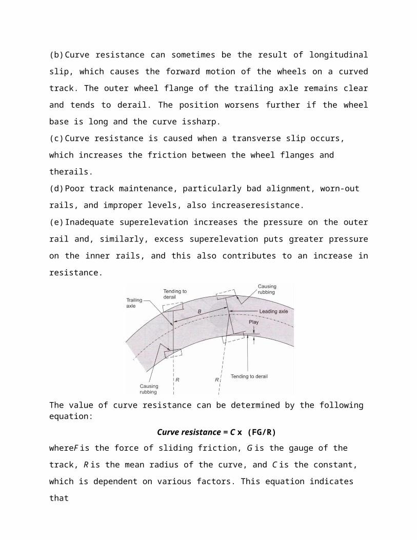
Table Comparison of different types of ballast
Type
ballast
of Advantages Disadvantages Suitability
Sand ballast Good drainage properties Causes excessive wear Suitable for
sleeper tracks
CI pot
Cheap Blows off easily Not suitable for
No noise produced on the
track
Poor retentivity of packing high-speed tracks
Good packing material for
CI sleepers
Track cannot be maintained
to high standards
Moorum
ballast
Cheap, if locally available Very soft and turns into dust Used as a sub-ballast
Prevents
percolating
water from Maintenance
difficult
of track is Initial ballast
construction
for new
Provides good aesthetics Quality of track average
Coal
cinder
ash or Easy availability
on railways
Harmful for steel sleepers Normally used in yards
and sidings
Very cheap Corrodes rail bottom and
steel sleepers
Suitable for repairs of
formations during floods
and emergencies
Good drainage Soft and easily pulverized Not fit
tracks
for high-speed
Maintenance is difficult
Broken
ballast
stone Hard and durable when
procured from hard rocks
Initial cost is high Suitable for packing with
track machines
Good drainage properties Difficulties in procurement Suitable for high speed
tracks
Stable and resilient to the
track
Angular shape may injure
wooden sleepers
. Economical in the long run
REQUIREMENTS OF GOOD BALLAST
Ballast material should possess the following properties,
a) It should be tough and wearresistant.
b) It should be hard so that it does not get crushed under the movingloads,
c) It should be generally cubical with sharpedges.
d) It should be non-porous and should not absorb water.
e) It should resist both attrition andabrasion.
f) It should be durable and should not get pulverized or disintegrated under adverse weather
conditions
(g) It should allow for good drainage ofwater,
(h) It should be cheap andeconomical.
DESIGN OF BALLAST SECTION
The design of the ballast section includes the determination of the depth of the ballast cushion
below the sleeper and its profile. These aspects are discussed as follows.
Minimum Depth of Ballast Cushion
The load on the sleeper is transferred through the medium of the ballast to the formation. The
pressure distribution in the ballast section depends upon the size and shape of the ballast and the
degree of consolidation. Though the lines of equal pressure are in the shape of a bulb as
discussed in, yet for simplicity, the dispersion of load can be assumed to be roughly 45° to the
vertical. In order to ensure that the load is transferred evenly on the formation, the depth of the
ballast should be such that the dispersion lines do not overlap each other. For the even
distribution of load on the formation, the depth of the ballast is determined by the following
formula:
Sleeper spacing = width of the sleeper + 2 x depth of ballast
Minimum Depth of the Ballast Cushion
Introduction
Lecture-
10FORMATI
ON
Subgrade is the naturally occuring soil which is prepared to receive the ballast. The prepared flat
surface, which is ready to receive the ballast, along with sleeps and rails, is called the formation.
The formation is an important constituent of the track, as it supports the entire track structure. It
has the following functions:
(a) It provides a smooth and uniform bed for laying thetrack.
(b) It bears the load transmitted to it from the moving load through theballa
(c) It facilitatesdrainage.
(d) It provides stability to thetrack.
GENERAL DESCRIPTION OF FORMATION
The formation can be in the shape of an embankment or a cutting. When formation is in the
shape of a raised bank constructed above the natural ground, it is called an embankment. The
formation at a level below the natural ground is called a cutting. Normally, a cutting or an
excavation is made through a hilly or natural ground for providing the railway line at the
required level below the ground level.
The formation (Fig. below) is prepared either by providing additional earthwork over the existing
ground to make an embankment or by excavating the existing ground surface to make a cutting.
The formation can thus be in the shape of either an embankment or a cutting. The height of the
formation depends upon the ground contours and the gradients adopted. The side slope of the
embankment depends upon the shearing strength of the soil and its angle of repose. The width of
the formation depends upon the number of tracks to be laid, the gauge, and such other factors.
The recommended widths of formation as adopted on Indian Railway BG MG. and NG are given
in Table below.

(a) Cross section ofbank
(b) Cross section ofcutting
Typical cross section of bank and cutting for BG double line (dimensions in mm)
Table. Width of formation for differenttracks
Gauge Type of sleepers Single-line section Double-line section
Bank width (m) Cutting width (m) Bank width
(m)
Cutting width (m)
BG W,* ST,! and
concrete
6.85 6.25 12.155 11.555
MG W, ST, CST-9, and
concrete
5.85 5.25 9.81 9.21
NG W, ST, and CST-9 3.70 3.35 7.32 7.01
W stands for wooden sleepers. ST stands for steel trough sleeper.
Slopes of Formation
The side slopes of both the embankment and the cutting depend upon the shearing strength of the
soil and its angle of repose. The stability of the slope is generally determined by the slip circle
method. In actual practice, average soil such as sand or clay may require a slope of 2:1
(horizontal: vertical) for an embankment and 1:1 or 0.5:1 or even steeper particularly when rock
is available for cutting.
To prevent erosion of the side slopes due to rain water, etc., the side slopes are turfed. A thin
layer of cohesive soil is used for this purpose. Alternatively, the slopes are turfed with a suitable
type of grass. Sometimes the bank also gets eroded due to standing water in the adjoining land. A
toe and pitching are provided in such cases.
Permanent way is the generic term for the track (rails, sleepers and ballast) on which railway
trains run. Although the configuration of the track today would be recognized by engineers of the
19th century, it has developed significantly over the years as technological improvements
became available, and as the demands of train operation increased.
Requirement of Good Track
A permanent way or track should provide comfortable and safe ride at the maximum permissible
speed with minimum maintenance cost. To achieve these objectives, a sound permanet way
should have the following characteristics:
The gauge should be correct anduniform.
The rail should have perfect cross levels. In curves, the outer rail should have proper
super elevation to take into account the centrifugalforce.
The alignment should be straight and free of kinks. In the case of curves, a proper
transition should be provided between the straight track and thecurve.
The gradient should be uniform and as gentle as possible. The change of gradient should
be followed by a proper vertical curve to provide a smoothride.
The track should be resilient and elastic in order to absorb the shocks and vibration of
runningtrains.
The track should have a good drainage system so that the stability of the track is not
effected by waterlogging.
The track should have good lateral strength so that it can maintain its stability despite
variations in temperature and other suchfactors.
There should be provisions for easy replacement and renewal of the various track
components.
The track should have such a structure that not only is its initial cost low, but also its
maintenance cost is minimum.
REQUIREMENTS OF AN IDEAL PERMANENT WAY
The following are the principal requirements of an ideal permanent way or of a good railway
track :-
i. The gauge of the permanent way should be uniform, correct and it should not getaltered.
ii. Both the rails should be at the same level on tangent (straight) portion of thetrack.
iii. Proper amount of superelevationshould be provided to the outer rail above the inner rail
on curved portion of thetrack.
iv. The permanent way should be sufficiently strong against lateralforces.
v. The curves, provided in the track, should be properlydesigned.
vi. An even and uniform gradient should be provided through out the length of thetrack.
vii. The tractive resistance of the track should beminimum.
viii. The design of the permanent way should be such that the load of the train is uniformly
distributed on both the rails so as to prevent unequal settlement of thetrack.
ix. It Should provide adequate elasticity in order to prevent the harshness of impacts between
the rails and the moving wheel loads of atrain.
x. It should be free from excessive rail joints and all the joining should be properly designed
andconstructed.
xi. All the components parts such as rails, sleepers, ballast, fixtures and fastenings, etc.
should satisfy the designrequirements.
xii. All the fixtures and fastenings such as chairs, bearing plates, fish plates, fish bolts,spikes
etc. should be strong enough to withstand the stresses occurring in the track.
xiii. All the *points and crossings, laid in the permanent way, should be properly designed
and carefullyconstructed.
xiv. It should be provided with fence near level crossings and also in urbanareas.
xv. It should be provided with proper drainage facilities so as to drain off the rain water
quickly away from thetrack.
xvi. It should be provided with safe and strong bridges coming in the alignment of thetrack.
xvii. It should be provided with safe and strong bridges coming in the alignment of thetrack.
xviii. It should be so constructed that repairs and renewals of any of its portion can be carried
out without anydifficulty.
RAIL WEAR
Lecture-11 WEAR
AND FAILURE INRAILS
Due to the passage of moving loads and friction between the rail and the wheel, the rail head gets
worn out in the course of service. The impact of moving loads, the effect of the forces of
acceleration, deceleration, and braking of wheels, the abrasion due to rail-wheel interaction, the
effects of weather conditions such as changes in temperature, snow, and rains, the presence of
materials such as sand, the standard of maintenance of the track, and such allied factors cause
considerable wear and tear of the vertical and lateral planes of the rail head. Lateral wear occurs
more on curves because of the lateral thrust exerted on the outer rail by centrifugal force. A lot of
the metal of the rail head gets worn out, causing the weight of the rail to decrease. This loss of
weight of the rail section should not be such that the stresses exceed their permissible values.
When such a stage is reached, rail renewal is called for.
In addition, the rail head should not wear to such an extent that there is the possibility of a worn
flange of the wheel hitting the fish plate.
Types of Wear on Rails
A rail may face wear and tear in the following positions:
(a) On top of the rail head (verticalwear)
(b) On the sides of the rail head (lateralwear)
(c) On the ends of the rail (battering of railends)
Wear is more prominent at some special locations of the track. These locations are normally the
following:
(a) On sharp curves, due to centrifugal forces
(b) On steep gradients, due to the extra force applied by theengine
(c) On approaches to railway stations, possibly due to acceleration anddeceleration
(d) In tunnels and coastal areas, due to humidity and weathereffects
Measurement of Wear
Wear on rails can be measured using any of the following methods:
(a) By weighing therail
(b) By profiling the rail section with the help of leadstrips

(c) By profiling the rail section with the help ofneedles
(d) By using special instruments designed to measure the profile of the rail and record it
simultaneously on graphpaper
Methods to Reduce Wear
Based on field experience, some of the methods adopted to reduce vertical wear and lateral wear
on straight paths and curves are as follows-
(a) Better maintenance of the track to ensure good packing as well as proper alignment and use
of the correct gauge
(b) Reduction in the number of joints bywelding
(c) Use of heavier and higher UTS rails, which are more wearresistant
(d) Use of bearing plates and proper adzing in case of woodensleepers
(e) Lubricating the gauge face of the outer rail in case ofcurves
(f) Providing check rails in the case of sharpcurves
(g) Interchanging the inner and outerrails
(h) Changing the rail by carrying out trackrenewal
Rail End Batter
The hammering action of moving loads on rail joints batters the rail ends in due course of time.
Due to the impact of the blows, the contact surfaces between the rails and sleepers also get worn
out, the ballast at places where the sleepers are joined gets shaken up, the fish bolts become
loose, and all these factors further worsen the situation, thereby increasing rail endbatter.
Rail end batter is measured as the difference between the height of the rail at the end and at a
point 30 cm away from the end. If the batter is up to 2 mm, it is classified 'average', and if it is
between 2 and 3 mm, it is classified as 'severe'. When rail end batter is excessive and the rail is
otherwise alright, the ends can be cropped and the rail reused.

OTHER DEFECTS IN RAILS
Rail wear and battering of rail ends are the two major defects in rails. However some other types
of defects may also develop in a rail and necessitate its removal in extreme cases. These are as
follows:
Hogging of rails
Rail ends get hogged due to poor maintenance of the rail joint, yielding format, loose and faulty
fastenings, and other such reasons. Hogging of rails causes the quality of the track to deteriorate.
This defect can be remedied by measured she packing.
Scabbing of rails
The scabbing of rails occurs due to the falling of patches or chunks of metal from the rail table.
Scabbing is generally seen in the shape of an elliptical depression; whose surface reveals a
progressive fracture with numerous cracks around it.
Wheel burns
Wheel burns are caused by the slipping of the driving wheel of locomotives on the rail surface.
As a consequence, extra heat is generated and the surface of the rail gets affected, resulting n a
depression on the rail table. Wheel burns are generally noticed on steep gradients or where there
are heavy incidences of braking or near water columns.
Shelling and black spots
Shelling is the progressive horizontal separation of metal that occurs on the gauge side,
generally at the upper gauge corner. It is primarily caused by heavy bearing pressure on a small
area of contact, which produces heavy internal shearstress.
Corrugation of rail:
Corrugation consists of minute depressions on the surface of rails, varying in shape and size and
occurring it irregular intervals. The exact cause of corrugation is not yet known, though many
theories have been put forward. The factors which help in the formation of rail corrugation,
however, are briefly enumerated here,
a) Metallurgy and age of rails
(i) High nitrogen content of the rails
(ii) Effect of oscillation at the time of rolling and straightening ofrails
(b) Physical and environment conditions oftrack

(i) Steep gradients (ii) Yielding formation (iii) Long tunnels (iv) Electrified sections
(c) Trainoperations
(i) High speeds and high axle loads (ii) Starting locations of trains (iii) Locations where brakes
are applied to stop the train
(d) Atmosphericeffects
(i) High moisture content in the air particularly in coastal areas (ii) Presence of sand
RAIL FAILURE
A rail is said to have failed if it is considered necessary to remove it immediately from the track
on account of the defects noticed on it. The majority of rail failures originate from the fatigue
cracks caused due to alternating stresses created in the rail section on account of the passage of
loads. A rail section is normally designed to take a certain minimum GMT of traffic, but
sometimes due to reasons such as an inherent defect in the metal, the section becomes weak at a
particular point and leads to premature failure of the rail.
(b) Physical and environment conditions of track
(i) Steep gradients (ii) Yielding formation (iii) Long tunnels (iv) Electrified sections
(c) Trainoperations
(i) High speeds and high axle loads (ii) Starting locations of trains (iii) Locations where brakes
are applied to stop the train
(d) Atmosphericeffects
(i) High moisture content in the air particularly in coastal areas (ii) Presence of sand
The corrugation of rails is quite an undesirable feature. When vehicles pass over corrugated rails,
a roaring sound is produced, possibly due to the locking of air in the corrugation. This
phenomenon is sometimes called 'Roaring of rails'. This unpleasant and excessive noise causes
great inconvenience to the passengers. Corrugation also results in the rapid oscillation of rails,
which in turn loosens the keys, causes excessive wear to fittings, and disturbs the packing.

Causes of Rail Failures
The main causes of failure of rails are as follows:
Inherent defects in the rail These are due to manufacturing defects in the rail, such as faulty
chemical composition, harmful segregation, piping, seams, laps, and guide marks.
Defects due to fault of the rolling stock and abnormal traffic effects Flat soots in tvres, engine
burns, skidding of wheels, severe braking, etc.
Excessive corrosion of rails This generally takes place due to weather conditions, the presence
of corrosive salts such as chlorides and constant exposure of the rails to moisture and humidity in
locations near water columns, ashpits, tunnels, etc. Corrosion normally leads to the development
of cracks in regions with a high concentration of stresses.
Badly maintained joints Poor maintenance of joints such as improper packing of joint sleepers
and loose fittings.
Defects in welding of joints These defects arise either because of improper composition of the
thermit weld metal or because of a defective welding technique.
Improper maintenance of track Ineffective or careless maintenance of the track or delayed
renewal of the track.
Derailments The rails are damaged duringderailment.
Classification of Rail Failures
The classification of rail failures on Indian Railways has been codified for easy processing of
statistical data. The code is made up of two portions—the first portion consisting of three code
letters and the second portion consisting of three or four code digits.
First portion of the code The three code letters make up the first portion and denote the
following.
(i) Type of rail being used (O for plain rail and X for points and crossing rails) (ii) Reasons for
withdrawal of rail (F for fractured, C for cracked, and D for defective)
(iii) Probable cause failure (S for fault of rolling stock, C for excessive corrosion, D for
derailment, and O for others)
Second portion of code The second portion consisting of three or four digits gives the following
information, (i) First digit indicate the location of the fracture on the length of the rail (1 for

within fish plate limits and 2 for other portions on the rail), (ii) Second digit indicate the position
in the rail section from where the failure started (0 for unknown, 1 for within rail head, 2 for
surface of rail head, 3 for web, and 4 for foot).
(iii) Third digit indicate the direction of crack or fracture (0 to 9). (iv) Any other information
about the fracture, where it is necessary to provide further subdivision. No specific system is
recommended for this code.
Metallurgical Investigation
The following types of defective rails should normally be sent for metallurgical investigation, (i)
Rails that have been removed from the track as a result of visual or ultrasonic detection
(ii) Rail failures falling in categories in which cracks or surface defects develop at specified
locations

Introduction
Lecture-
12CREEP OF
RAIL
Creep is defined as the longitudinal movement of the rail with respect to the sleepers. Rails have
a tendency to gradually move in the direction of dominant traffic. Creep is common to all
railway tracks, but its magnitude varies considerably from place to place; the rail may move by
several centimeters in a month at few places, while at other locations the movement may be
almostnegligible.
THEORIES FOR THE DEVELOPMENT OF CREEP
Various theories have been put forward to explain the phenomenon of creep and its causes, but
none of them have proved to be satisfactory. The important theories are briefly discussed in the
following subsections.
Wave Motion Theory
According to wave motion theory, wave motion is set up in the resilient track because of moving
loads, causing a deflection in the rail under the load. The portion of the rail immediately under
the wheel gets slightly depressed due to the wheel load. Therefore, the rails generally have a
wavyformation.
Percussion Theory
According to percussion theory, creep is developed due to the impact of wheels at the rail end
ahead of a joint. As the wheels of the moving train leave the trailing rail at the joint, the rail gets
pushed forward causing it to move longitudinally in the direction of traffic, and that is how creep
develops. Though the impact of a single wheel may be nominal, the continuous movement of
several wheels passing over the joint pushes the facing or landing rail forward, thereby causing
creep.
Drag Theory
According to drag theory, the backward thrust of the driving wheels of a locomotive has the
tendency to push the rail backwards, while the thrust of the other wheels of the locomotive and
trailing wagons pushes the rail in the direction in which the locomotive is moving. This results in
the longitudinal movement of the rail in the direction of traffic, thereby causing creep.
CAUSES OF CREEP
The main factors responsible for the development of creep are as follows.
Ironing effect of the wheel The ironing effect of moving wheels on the waves formed in the rail
tends to cause the rail to move in the direction of traffic, resulting in creep.
Starting and stopping operations When a train starts or accelerates, the backward thrust of its
wheels tends to push the rail backwards. Similarly, when the train slows down or comes to a halt,
the effect of the applied brakes tends to push the rail forward. This in turn causes creep in one
direction or the other.
Changes in temperature Creep can also develop due to variations in temperature resulting in
the expansion and contraction of the rail. Creep occurs frequently during hot weather conditions.
Unbalanced traffic Ina double-line section, trains move only in one direction, i.e., each track is
unidirectional. Creep, therefore, develops in the direction of traffic. In a single-line section, even
though traffic moves in both directions, the volume of traffic in each direction is normally
variable. Creep, therefore, develops in the direction of predominanttraffic.
Poor maintenance of track Some minor factors, mostly relating to poor maintenance of the
track, also contribute to the development of creep. These are as follows:
• Improper securing of rails tosleepers
• Limited quantities of ballast resulting in inadequate ballast resistance to the movement of
sleepers
• Improper expansion gaps
• Badly maintained railjoints
• Rail seat wear in metal sleepertrack
• Rails too light for the traffic carried onthem
• Yielding formations that result in uneven crosslevels
• Other miscellaneous factors such as lack of drainage, and loose packing, uneven spacing of
sleepers
EFFECTS OF CREEP
The following are the common effects of creep.
Sleepers out of square The sleepers move out of their position as a result of creep and become
out of square. This in turn affects the gauge and alignment of the track, which finally results in
unpleasant rides.
Expansion in gaps get disturbed Due to creep, the expansion gaps widen at some places and
close at others. This results in the joints getting jammed. Undue stresses are created in the fish
plates and bolts, which affect the smooth working of the switch expansion joints in the case of
long welded rails.
Distortion of points and crossings Due to excessive creep, it becomes difficult to maintain the
correct gauge and alignment of the rails at points and crossings.
Difficulty in changing rails If, due to operational reasons, it is required that the rail be changed,
the same becomes difficult as the new rail is found to be either too short or too long because of
creep.
Effect on interlocking The interlocking mechanism of the points and crossings pets disturbed bv
creep.
Possible buckling of track Ifthe creep is excessive and there is negligence in the maintenance
of the track, the possibility of buckling of the track cannot be ruledout.
Other effects There are other miscellaneous effects of creep such as breaking of bolts and kinks
in the alignment, which occur in various situations.
MEASUREMENT OF CREEP
Creep can be measured with the help of a device called creep indicator. It consists of two creep
posts, which are generally rail pieces that are driven at 1 km intervals on either side of the track.
For the purpose of easy measurement, their top level is generally at the same level as the rail.
Using a chisel, a mark is made at the side of the bottom flange of the rail on either side of the
track. A fishing string is then stretched between the two creep posts and the distance between the
chisel mark and the string is taken as the amount of creep.
According to the prescribed stipulations, creep should be measured at intervals of about three
months and noted in a prescribed register, which is to be maintained by the permanent way
inspector (PWI). Creep in excess of 150 mm (6 in.) should not be permitted on any track and not
more than six consecutive rails should be found jammed in a single-rail track at one location.
There should be no creep in approaches to points and crossings.
ADJUSTMENT OF CREEP
When creep is in excess of 150 mm resulting in maintenance problems, the same should be
adjusted by pulling the rails back. This work is carried out after the required engineering signals
have been put up and the necessary caution orders given. The various steps involved in the
adjustment of creep are as follows:
(i) A careful survey of the expansion gaps and of the current position of rail joints is carried
out.
(ii) The total creep that has been proposed to be adjusted and the correct expansion gap that
is to be kept are decided inadvance.
(iii) The fish plates at one end are loosened and those at the other end are removed. Sleeper
fittings, i.e., spikes or keys, are also loosened orremoved.
(iv) The rails are then pulled back one by one with the help of a rope attached to a hook. The
pulling back should be regulated in such a way that the rail joints remain central and
suspended on the jointsleepers.
The pulling back of rails is a slow process since only one rail is dealt with at a time and can
be done only for short isolated lengths of a track. Normally, about 40-50 men are required
per kilometre for adjusting creep. When creep is required to be adjusted for longer lengths,
five rail lengths are tackled at a time. The procedure is almost the same as the precedingsteps

except that instead of pulling the rails with i rope, a blow is given to them using a cut rail
piece of a length of about 5 m.
CREEP ADJUSTER
A creep adjuster is normally used when extensive work is involved. The creep adjuster is set at
the centre of the length of the track, to be tackled, with the wide joints behind it and the jammed
joints ahead of it. The following steps are adopted while using a creep adjuster:
(i) Expansion liners of the correct size are put in all the expansiongaps,
(ii) All the keys on the side (with wide joints) of the creep adjuster are removed and all fish
boltsloosened,
(iii) The creep adjuster is then used to close up the gaps to the required extent by pushing the
rails forward. A gap of a few inches is left between the rail ends opposite theadjuster,
(iv) The corrected rails are then fastened with keys. After that, the rails on the other side of
the adjuster aretackled,
(v) The operation leaves some of the expansion gaps too wide which are tackled by the creep
adjuster when it is set in the nextposition,
(vi) The corrected rails are then fastened and the adjuster is shifted to the newposition,
(vii) The whole process is repeated again and again till the requisite attention has been paid to
the entire length of the rail. In the end it may be necessary to use a rail with the correct
size of closure (bigger or smaller) to complete thework.

Introduction
Lecture-
13RAIL
JOINTS
Although a rail joint has always been an integral part of the railway track, it is looked upon as a
necessary evil because of the various problems that it presents. Earlier, rails were rolled in short
lengths due to difficulties in rolling and the problem of transportation. With increase in
temperature, rails expand and this expansion needs to be considered at the joints. It was,
therefore, felt that the longer the rail, the larger the required expansion gap, and this too limited
the length of the rail. A rail joint is thus an inevitable feature of railway tracks, even though it
presents a lot of problems in the maintenance of the permanent way. This chapter discusses the
various types of rail joints and their suitability on a railway track.
ILL EFFECTS OF A RAIL JOINT
A rail joint is the weakest link in the track. At a joint, there is a break in the continuity of the rail
in both the horizontal and the vertical planes because of the presence of the expansion gap and
imperfection in the levels of rail heads. A severe jolt is also experienced at the rail joint when the
wheels of vehicles negotiate the expansion gap. This jolt loosens the ballast under the sleeper
bed, making the maintenance of the joint difficult. The fittings at the joint also become loose,
causing heavy wear and tear of the track material. Some of the problems associated with the rail
joint are asfollows.
Maintenanceeffort
Due to the impact of moving loads on the joint, the packing under the sleeper loosens and the
geometry of the track gets distorted very quickly because of which the joint requires frequent
attention. It is generally seen that about 30 per cent extra labour is required for maintenance of a
joint.

Bonded main line 6-bolt rail joint on a segment of 76.9 kg/m rail. Note how bolts are oppositely
oriented to prevent complete separation of the joint in the event of being struck by a wheel
during aderailment.
Lifespan
The life of rails, sleepers, and fastenings gets adversely affected due to the extra stresses created
by the impact of moving loads on the rail joint. The rail ends particularly get battered and hogged
and chances of rail fracture at joints are considerably high due to fatigue stresses in the rail ends.
Noise effect
A lot of noise pollution is created due to rail joints, making rail travel uncomfortable.
Sabotage chances
Wherever there is a rail joint, there is a potential danger of the removal of fish plates and rails by
miscreants and greater susceptibility to sabotage.
Impact on quality
The quality of the track suffers because of excessive wear and tear of track components and
rolling stock caused by rail joints.
Fuel consumption
The presence of rail joints results in increased fuel consumption because of the extra effort
required by the locomotive to haul the train over these joints.
REQUIREMENTS OF AN IDEAL RAIL JOINT
An ideal rail joint provides the same strength and stiffness as the parent rail. The characteristics
of an ideal rail joint are briefly summarized here.
Holding the rail ends:An ideal rail joint should hold both the rail ends in their precise location
in the horizontal as well as the vertical planes to provide as much continuity in the track as
possible. This helps in avoiding wheel jumping or the deviation of the wheel from its normal
path ofmovement.
Strength: An ideal rail joint should have the same strength and stiffness as the parent rails it
joins.
Expansion gap:The joint should provide an adequate expansion gap for the free expansion and
contraction of rails caused by changes in temperature
Flexibility It should provide flexibility for the easy replacement of rails, whenever required.
Provision for wear:It should provide for the wear of the rail ends, which is likely to occur under
normal operating conditions.
Elasticity:It should provide adequate elasticity as well as resistance to longitudinal forces so as
to ensure a trouble-freetrack.
Cost:The initial as well as maintenance costs of an ideal rail joint should be minimal.
TYPES OF RAIL JOINTS
The nomenclature of rail joints depends upon the position of the sleepers or the joints.
Classification According to Position of Sleepers
Three types of rail joints come under this category.
Supported joint
In this type of joint, the ends of the rails are supported directly on the sleeper. It was expected
that supporting the joint would reduce the wear and tear of the rails, as there would be no
cantilever action. In practice, however, the support tends to slightly raise the height of the rail
ends. As such, the run on a supported joint is normally hard. There is also wear and tear of the
sleeper supporting the joint and its maintenance presents quite a problem. The duplex sleeper is
an example of a supported joint (Fig.below).
Fig.Supported rail joint
Suspended joint
In this type of joint, the ends of the rails are suspended between two sleepers and some portion of
the rail is cantilevered at the joint. As a result of cantilever action, the packing under the sleepers
of the joint becomes loose particularly due to the hammering action of the moving train loads.
Suspended joints are the most common type of joints adopted by railway systems worldwide,
including India (Fig. 16.2).
Fig.Suspended joint
Bridge joints
The bridge joint is similar to the suspended joint except that the two sleepers on either side of a
bridge joint are connected by means of a metal flat [Fig. (a)] or a corrugated plate known as a
bridge plate [Fig. 16.3(b)]. This type of joint is generally not used on Indian Railways.
Fig. (a) Bridge joint with metal flat Joint
Fig. (b) Bridge joint with bridge plate
Classification Based on the Position of the Joint
Two types of rail joints fall in this category.
Square joint In this case, the joints in one rail are exactly opposite to the joints in the other rail.
This type of joint is most common on Indian Railways (Fig. below).
Staggered joint In this case, the joints in one rail are somewhat staggered and are not opposite
the joints in the other rail. Staggered joints are normally preferred on curved tracks because they
hinder the centrifugal force that pushes the track outward (Fig. below).

WELDING A RAIL JOINT
The purpose of welding is to join rail ends together by the application of heat and thus eliminate
the evil effects of rail joints.
There are four welding methods used in railways.
a) Gas pressurewelding
b) Electric arc or metal arcwelding
c) Flash butt welding
d)Thermitwelding

Lecture-14
BEARING PLATES, ANTI-CREEP DEVICES
ADJUSTMENT OF CREEP
When creep is in excess of 150 mm resulting in maintenance problems, the same should be
adjusted by pulling the rails back. This work is carried out after the required engineering signals
have been put up and the necessary caution orders given. The various steps involved in the
adjustment of creep are as follows:
(v) A careful survey of the expansion gaps and of the current position of rail joints is carried
out.
(vi) The total creep that has been proposed to be adjusted and the correct expansion gap that
is to be kept are decided inadvance.
(vii) The fish plates at one end are loosened and those at the other end are removed. Sleeper
fittings, i.e., spikes or keys, are also loosened orremoved.
(viii) The rails are then pulled back one by one with the help of a rope attached to a hook. The
pulling back should be regulated in such a way that the rail joints remain central and
suspended on the jointsleepers.
The pulling back of rails is a slow process since only one rail is dealt with at a time and can
be done only for short isolated lengths of a track. Normally, about 40-50 men are required
per kilometre for adjusting creep. When creep is required to be adjusted for longer lengths,
five rail lengths are tackled at a time. The procedure is almost the same as the preceding steps
except that instead of pulling the rails with i rope, a blow is given to them using a cut rail
piece of a length of about 5 m.
CREEP ADJUSTER
A creep adjuster is normally used when extensive work is involved. The creep adjuster is set at
the centre of the length of the track, to be tackled, with the wide joints behind it and the jammed
joints ahead of it. The following steps are adopted while using a creep adjuster:
(viii) Expansion liners of the correct size are put in all the expansiongaps,
(ix) All the keys on the side (with wide joints) of the creep adjuster are removed and all fish
boltsloosened,
(x) The creep adjuster is then used to close up the gaps to the required extent by pushing the
rails forward. A gap of a few inches is left between the rail ends opposite theadjuster,
(xi) The corrected rails are then fastened with keys. After that, the rails on the other side of
the adjuster aretackled,
(xii) The operation leaves some of the expansion gaps too wide which are tackled by the creep
adjuster when it is set in the nextposition,
(xiii) The corrected rails are then fastened and the adjuster is shifted to the newposition,
(xiv) The whole process is repeated again and again till the requisite attention has been paid to
the entire length of the rail. In the end it may be necessary to use a rail with the correct
size of closure (bigger or smaller) to complete thework.
PORTIONS OF TRACK SUSCEPTIBLE TO CREEP
The following locations of a track are normally more susceptible to creep.
• The point where a steel sleeper track or CST-9 sleeper track meets a wooden sleepertrack
• Dips in stretches with longgradients
• Approaches to major girder bridges or other stablestructures
• Approaches to level crossings and points andcrossings
• Steep gradients and sharpcurves
MEASURES TO REDUCE CREEP
To reduce creep in a track, it should be ensured that the rails are held firmly to the sleepers and
that adequate ballast resistance is available. All spikes, screws, and keys should be driven home.
The toe load of fastenings should always be slightly more than the ballast resistance. Creep
anchors can effectively reduce the creep in a track. At least eight of these creep anchors must be
provided per panel. Out of the large number of creep anchors tried on Indian Railways, the 'fair
T' and 'fair V anchors, have been standardized for use. The fair 'V anchor, which is more popular,
is shown in Fig. below. The creep anchor should fit snugly against the sleeper for it to be full;-
effective. The following measures are also helpful in reducingcreep,
(a) The track should be well maintained—sleepers should be properly packed and the crib and
shoulder ballast should be wellcompacted.

(b) A careful lookout should be kept for jammed joints that exist in series. In the case of a fish-
plated track, more than six consecutive continuously jammed joints should not be permitted. In
the case of SWR tracks, more than two consecutive jammed joints should not be permitted at rail
temperatures lower than the maximum daily temperature (Tm) in the case of zones I and II and
lower than (Tm - 5°C) in the case of zones III and IV. Regular adjustment may be necessitated
on girderbridges.
(c) Anticreep bearing plates should be provided on wooden sleepers to arrest creep, but joints
sleepers should have standard canted bearing plates with railscrews.

INTRODUCTION
Lecture-
15RAILWAY
ALIGNMENT
Geometric design of a railway track discusses all those parameters which affect the geometry of
the track. These parameters are as follows:
1. Gradients in the track, including grade compensation, rising gradient, and fallinggradient
2. Curvature of the track, including horizontal and vertical curves, transition curves, sharpness of
the curve in terms of radius or degree of the curve, cant or superelevation on curves,etc.
3. Alignment of the track, including straight as well as curvedalignment
It is very important for tracks to have proper geometric design in order to ensure the safe and
smooth running of trains at maximum permissible speeds, carrying the heaviest axle loads. The
speed and axle load of the train are very important and sometimes are also included as
parameters to be considered while arriving at the geometric design of thetrack.
NECESSITY FOR GEOMETRIC DESIGN
The need for proper geometric design of a track arises because of the following considerations:
(a) To ensure the smooth and safe running oftrains
(b) To achieve maximumspeeds
(c) To carry heavy axleloads
(d) To avoid accidents and derailments due to a defective permanentway
(e) To ensure that the track requires leastmaintenance
(f) For good aesthetics
DETAILS OF GEOMETRIC DESIGN OF TRACK
The geometric design of the track deals with alignment of railway track and Curves Details
regarding curves and their various aspects.
GRADIENTS
Gradients are provided to negotiate the rise or fall in the level of the railway track. A rising
gradient is one in which the track rises in the direction of movement of traffic and in a down or
falling gradient the track loses elevation the direction of movement of traffic.
A gradient is normally represented by the distance travelled for a rise or fall of one unit.
Sometimes the gradient is indicated as per cent rise or fall. For example, if there is a rise of 1 m
in 400 m, the gradient is 1 in 400 or 0.25 percent.
Gradients are provided to meet the following objectives:
(a) To reach various stations at differentelevations
(b) To follow the natural contours of the ground to the extentpossible
(c) To reduce the cost of earthwork
The following types of gradients are used on the railways:
(a) Rulinggradient
(b) Pusher or helpergradient
(c) Momentumgradient
(d) Gradients in stationyards
Ruling Gradient
The ruling gradient is the steepest gradient that exists in a section. It determines the maximum
load that can be hauled by a locomotive on that section. While deciding the ruling gradient of a
section, it is not only the severity of the gradient, but also its length as well as its position with
respect to the gradients on both sides that have to be taken into consideration. The power of the
locomotive to be put into service on the track also plays an important role in taking this decision,
as the locomotive should have adequate power to haul the entire load over the ruling gradient at
the maximum permissible speed.
In plain terrain: 1 in 150 to 1 in 250
In hilly terrain: 1 in 100 to 1 in 150
Once a ruling gradient has been specified for a section, all other gradients provided in that
section should be flatter than the ruling gradient after making due compensation forcurvature.
Pusher or Helper Gradient
In hilly areas, the rate of rise of the terrain becomes very important when trying to reduce the
length of the railway line and, therefore, sometimes, gradients steeper than the ruling gradient are
provided to reduce the overall cost. In such situations, one locomotive is not adequate to pull the
entire load, and an extra locomotive is required.

When the gradient of the ensuing section is so steep as to necessitate the use of an extra engine
for pushing the train, it is known as a pusher or helper gradient. Examples of pusher gradients are
the Budni-Barkhera section of Central Railway and the Darjeeling Himalayan Railway section.
Momentum Gradient
The momentum gradient is also steeper than the ruling gradient and can be overcome by a train
because of the momentum it gathers while running on the section. In valleys, a falling gradient is
sometimes followed by a rising gradient. In such a situation, a train coming down a falling
gradient acquires good speed and momentum, which gives additional kinetic energy to the train
and allows it to negotiate gradients steeper than the ruling gradient. In sections with momentum
gradients there are no obstacles provided in the form of signals, etc., which may bring the train to
a critical juncture.
Gradients in Station Yards
The gradients in station yards are quite flat due to the following reasons:
(a) It prevents standing vehicles from rolling and moving away from the yard due to the
combined effect of gravity and strongwinds.
(b) It reduces the additional resistive forces required to start a locomotive to the extent possible.
It may be mentioned here that generally, yards are not levelled completely and certain flat
gradients are provided in order to ensure good drainage. The maximum gradient prescribed in
station yards on Indian Railways is 1 in 400, while the recommended gradient is 1 in1000.
GRADE COMPENSATION ON CURVES
Curves provide extra resistance to the movement of trains. As a result, gradients are compensated
to the following extent on curves:
(a) On BG tracks, 0.04 per cent per degree of the curve or 70/R, whichever isminimum
(b) On MG tracks, 0.03 per cent per degree of curve or 52.5/R, whichever isminimum
(c) On NG tracks, 0.02 per cent per degree of curve or 35/R, whichever isminimum
where R is the radius of the curve in metres. The gradient of a curved portion of the section
should be flatter than the ruling gradient because of the extra resistance offered by the curve.
Introduction
Lecture-
16HORIZONTAL
CURVES
Curves are introduced on a railway track to bypass obstacles, to provide longer and easily
traversed gradients, and to pass a railway line through obligatory or desirable locations.
Horizontal curves are provided when a change in the direction of the track is required and
vertical curves are provided at points where two gradients meet or where a gradient meets level
ground. To provide comfortable ride on a horizontal curve, the level of the outer rail is raised
above the level of the inner rail. This is known as superelevation.
CIRCULAR CURVES
This section describes the defining parameters, elements, and methods of setting out circular
curves.
Radius or degree of a curve
A curve is denned either by its radius or by its degree. The degree of a curve (D) is the angle
subtended at its centre by a 30.5 m or 100 ft arc.
The value of the degree of the curve can be determined as indicated below.
Circumference of a circle = 2πR
Angle subtended at the centre by a circle with this circumference = 360°
Angle subtended at the centre by a 30.5 m arc, or degree of curve = 360°/2πR x30.5
= 1 750/R (approximately R is in meter)
In cases where the radius is very large, the arc of a circle is almost equal to the chord connecting
the two ends of the arc. The degree of the curve is thus given by the following formulae:
D = 1750/R (when R is in metres)
D = 5730/ R (when R is in feet) A 2° curve, therefore, has a radius of 1750/2 = 875 m.
Relationship between radius and versine of a curve
Versine is the perpendicular distance of the midpoint of a chord from the arc of a circle. The
relationship between the radius and versine of a curve can be established as shown in Fig. Below.
Let R be the radius of the curve, C be the length of the chord, and V be the versine of a chord of
length C.

AC and DE being two chords meeting perpendicularly at a common point B, simple geometry
can prove that
Fig.Relation between radius and versine of a curve
AB x BC = DB x BE or V(2R-V) =(C/2) x (C/2) or 2RV- V2 = C2/4
V being very small, V2can be neglected. Therefore,
2RV = C2/4 or V = C2/8R
In above EqnV, C, and R are in the same unit, say, metres or centimetres. This general equation
can be used to determine versines if the chord and the radius of a curve are known.
Maximum degree of a curve
The maximum permissible degree of a curve on a track depends on various factors such as
gauge, wheel base of the vehicle, maximum permissible superelevation, and other such allied
factors. The maximum degree or the minimum radius of the curve permitted on Indian Railways
for various gauges is given in Tablebelow.
Table Maximum permissible degree ofcurves
Gauge On plain track On turnouts

Max. degree Min. radius (m) Max. degree Min. radius (m)
BG 10 175 8 218
MG 16 109 15 116
NG 40 44 17 103
Elements of a circular curve
In Fig. below, AO and BO are two tangents of a circular curve which meet or intersect at a point
O, called the point of inter section or apex. T1 and T2 are the points where the curve touches the
tangents, called tangent points (TP). OT1 and OT2 are the tangent lengths of the curve and are
equal in the case of a simple curve. T1T2 is the chord and EF is the versine of the same. Theangle
AOB formed between the tangents AO and OB is called the angle of intersection (∟1) and the
angle BOO1, is the angle of deflection (∟ ϕ). The following are some of the important relations
between theseelements:
∟1 + ∟ ϕ =1800
Tangent OT1 = OT2 = R tan (ϕ/2)
T1T2 = length of long cord = 2R sin (ϕ/2) Length
of the curve = 2πR/360 x ϕ = πR ϕ / 180
Fig. Elements of a circularcurve

Lecture-
17SUPERELEVATI
ON
The following terms are frequently used in the design of horizontal curves.
Superelevation or cant (Ca) Itis the difference in height between the outer and the inner rail on a
curve. It is provided by gradually raising the outer rail above the level of the inner rail. The inner
rail, also known as the gradient rail, is taken as the reference rail and is normally maintained at
its original level. The main functions of superelevation are thefollowing:
(a) To ensure a better distribution of load on bothrails
(b) To reduce the wear and tear of the rails and rollingstock
(c) To neutralize the effect of lateralforces
(d) To provide comfort to passengers
Equilibrium speed When the speed of a vehicle negotiating a curved track is such that the
resultant force of the weight of the vehicle and of radial acceleration is perpendicular to the plane
of the rails, the vehicle is not subjected to any unbalanced radial acceleration and is said to be in
equilibrium. This particular speed is called the equilibrium speed.
Maximum permissible speed This is the highest speed permitted to a train on a curve taking
into consideration the radius of curvature, actual cant, cant deficiency, cant excess, and the
length of transition. On curves where the maximum permissible speed is less than the maximum
sectional speed of the section of the line, permanent speed restriction becomesnecessary.
Cant deficiency (Cd) It occurs when a train travels around a curve at a speed higher than the
equilibrium speed. It is the difference between the theoretical cant required for such high speeds
and the actual cant provided.
Cant excess (Ce) It occurs when a train travels around a curve at a speed lower than the
equilibrium speed. It is the difference between the actual cant provided and the theoretical cant
required for such a low speed.
Cant gradient and cant deficiency gradient These indicate the increase or decrease in the cant
or the deficiency of cant in a given length of transition. A gradient of 1 in 1000 means that a cant
or a deficiency of cant of 1 mm is attained or lost in every 1000 mm of transition length.
Rate of change of cant or cant deficiency This is the rate at which cant deficiency increases
while passing over the transition curve, e.g., a rate of 35 mm per second means that a vehicle will
experience a change in cant or a cant deficiency of 35 mm in each second of travel over the
transition when travelling at the maximum permissible speed.
CENTRIFUGAL FORCE ON A CURVED TRACK
A vehicle has a tendency to travel in a straight direction, which is tangential to the curve, even
when it moves on a circular curve. As a result, the vehicle is subjected to a constant radial
acceleration. Radial acceleration = a = V2/R
whereV is the velocity (metres per second) and R is the radius of curve (metres). This radial
acceleration produces a centrifugal force which acts in a radial direction away from the centre.
The value of the centrifugal force is given by the formula:
Force = mass * acceleration, F = m x (V2/R) = (W/g)x (V2/R)
whereF is the centrifugal force (Kilo newton), W is the weight of the vehicle (tonnes), V is the
speed (m/s), g is the acceleration due to gravity (m/s2), and R is the radius of the curve in metres.
To counteract the effect of the centrifugal force, the outer rail of the curve is elevated with
respect to the inner rail by an amount equal to the superelevation. A state of equilibrium is
reached when both the wheels exert equal pressure on the rails and the superelevation is enough
to bring the resultant of the centrifugal force and the force exerted by the weight of the vehicle at
right angles to the plane of the top surface of the rails. In this state of equilibrium, the difference
in the heights of the outer and inner rails of the curve is known as equilibriumsuperelevation.
Fig.Equilibrium superelevation
Equilibrium Superelevation
In Fig. above, if θ is the angle that the inclined plane makes with the horizontal line, then
superelevation

tanθ = Superelevation / Gauge = e/ G
tan θ = Centrifugal force/weight = F/W
From these equations
e/G = F/W
e = f x G/W
e = W/g x V2/R x G/R = GV2 / gR
Here, e is the equilibrium superelevation, G is the gauge, Vis the velocity, g is the acceleration
due to gravity, and R is the radius of the curve. In the metric system equilibrium superelevation
is given by theformula:
e = GV2 / 127R
wheree is the superelevation in millimetres, V is the speed in km per hour, R is the radius of the
curve in metres, and G is the dynamic gauge in millimetres, which is equal to the sum of the
gauge and the width of the rail head in millimetres. This is ermal to 1750 mm for BG tracks and
1058 mm for MG tracks.
MAXIMUM VALUE OF SUPERELEVATION
The maximum value of superelevation has been laid down based on experiments carried out in
Europe on a standard gauge for the overturning velocity, taking into consideration the track
maintenance standards. The maximum value of superelevation generally adopted on on many
railways around the world is one-tenth to one-twelfth of the gauge. The values of maximum
superelevation prescribed on Indian Railways are given in Table below.
Table Maximum value of superelvation
Gauge Group Limiting value of cant (mm)
Under normal conditions With special permission of CE
BG A 165 185
BG B and C 165 -
BG D and E 140 -
MG All routes 90 100
NG 65 75
Lecture-18
CANT DEFICIENCY AND NEGATIVE SUPERELEVATIONIntroduction
Cant deficiency is the difference between the equilibrium cant that is necessary for the maximum
permissible speed on a curve and the actual cant provided. Cant deficiency is limited due to two
considerations:
1. Higher cant deficiency causes greater discomfort topassengers
2. Higher cant deficiency leads to greater unbalanced centrifugal force, which in turn leads to the
requirement of stronger tracks and fastenings to withstand the resultant greater lateral forces. The
maximum values of cant deficiency prescribed on Indian Railways are given in Table below.
Table Allowable cantdeficiency
Gauge Group Normal cant
deficiency (mm)
Remarks
BG AandB 75 For BG group
BG C, D, and
E
75 For A and B routes; 1 00 mm cant deficiency permitted
only for nominated rolling stock and routes withthe
approval of the CE
MG All routs 50
NG - 40
The limiting values of cant excess have also been prescribed. Cant excess should not be more
than 75 mm on BG and 65 mm on MG for all types of rolling stock. Cant excess should be
worked out taking into consideration the booked speed of the trains running on a particular
section. In the case of a section that carries predominantly goods traffic, cant excess should be
kept low to minimize wear on the inner rail. Table below lists the limiting values of the various
parameters that concern a curve.
NEGATIVE SUPERELEVATION
When the main line lies on a curve and has a turnout of contrary flexure leading to a branch line,
the superelevation necessary for the average speed of trains running over the main line curve
cannot be provided. In Fig. below, AB, which is the outer rail of the main line curve, must he
higher than CD. For the branch line, however CF should be higher than AE or point C should be

higher than point A. These two contradictory conditions cannot be met within one layout. In such
cases, the branch line curve has a negative superelevation and, therefore, speeds on both tracks
must be restricted, particularly on the branch line.
Fig: Negative superelevation
The provision of negative superelevation for the branch line and the reduction in speed over the
main line can be calculated as follows:
(i) The equilibrium superelevation for the branch line curve is first calculated using theformula
e = GV2 / 127R
(ii) The equilibrium superelevatione is reduced by the permissible cant deficiency Cd and the
resultant superelevation to be providedis
x = e - Cd
wherex is the superelevation, e is the equilibrium superelevation, and Cd is 75 mm for BG and 50
mm for MG. The value of Cd is generally higher than that of e, and, therefore, x is normally
negative. The branch line thus has a negative superelevation ofx.
(iii) The maximum permissible speed on the main line, which has a superelevation of x, is then
calculated by adding the allowable cant deficiency (x + Cd). The safe speed is also calculated and
the smaller of the two values is taken as the maximum permissible speed on the main line curve.
SAFE SPEED ONCURVES
For all practical purposes safe speed refers to a speed which protects a carriage from the danger
of overturning and derailment and provides a certain margin of safety. Earlier it was calculated
empirically by applying Martin's formula:
For BG and MG Transitioned curves
V = 3.65(R -6)1/2
where V is the speed in km per hour and R is the radius in metres.

Non-transitioned curves
Safe speed = four-fifths of the speed calculated using Eqn. above
For NG Transitioned curves
V = 3.65(R – 6)1/2 (subject to a maximum of 50 kmph).
Non-transitioned curves
V = 2.92(R – 6)1/2 (subject to a maximum of 40 kmph).
Indian Railways no longer follows this concept of safe speed on curves or the stipulations given
here.
New Formula for Determining Maximum Permissible Speed on Transitioned Curves
Earlier, Martin's formula was used to work out the maximum permissible speed or safe speed on
curves. This empirical formula has been changed by applying a formula based on theoretical
considerations as per the recommendations of the committee of directors, chief engineers, and
the ACRS. The maximum speed for transitioned curves is now determined as per the revised
formulae given below:
ForBG
V = ((Ca + Cd) x R/ 13.76)1/2 = 0.27((Ca + Cd) x R)1/2
whereV is the maximum speed in km per hour, Ca is the actual cant in millimetres, Cd is the
permitted cant deficiency in millimetres, and R is the radius in millimetres. This equation is
derived from Eqn for equilibrium superelevation and is based on the assumption that G = 1 750
mm, which is the centre-to-centre distance between the rail heads of a BG track with 52 g rails.
For MG
V = 0.347((Ca + Cd) x R)1/2
This is based on the assumption that the centre-to-centre (c/c) distance between the rail heads of
an MG track is 1058 mm.
For NG (762 mm.)
V = 3.65(R – 6 )1/2(subject to a maximum of 50 kmph)
(i) Maximum sanctioned speed of the section This is the maximum permissible speed
authorized by the commissioner of railway safety. This is determined after an analysis of the
condition of the track, the standard of interlocking, the type of locomotive and rolling stock used,
and other suchfactors.
(ii) Maximum speed of the section based on cant deficiency This is the speed calculated using
the formula given in Table above. First, the equilibrium speed is decided after taking various
factors into consideration and the equilibrium superelevation (Ca) calculated. The cant deficiency
(Cd) is then added to the equilibrium superelevation and the maximum speed is calculated as per
this increased superelevation (Ca +Cd).
(iii) Maximum speed taking into consideration speed of goods train andcant
excess Cant (Ca) is calculated based on the speed of slow moving traffic, i.e., goods train. This
speed is decided for each section after taking various factors into account, but generally its value
is 65 km per hour for BG and 50 km per hour for MG.
The maximum value of cant excess (Ce) is added to this cant and it should be ensured that the
cant for the maximum speed does not exceed the value of the sum of the actual cant + and the
cant excess (Ca + Ce).
(iv) Speed corresponding to the length of the transition curves This is the least value of speed
calculated after considering the various lengths of transition curves given by the formulae listed
in Tablebelow.
Example 1: Calculate the superelevation and maximum permissible speed for a 2° BG
transitioned curve on a high-speed route with a maximum sanctioned speed of 110 kmph. The
speed for calculating the equilibrium superelevation as decided by the chief engineer is 80 kmph
and the booked speed of goods trains is 50 kmph.
Example 2: Calculate the superelevation, maximum permissible speed, and transition length for
a 3° curve on a high-speed BG section with a maximum sanctioned speed of 110 kmph. Assume
the equilibrium speed to be 80 kmph and the booked speed of the goods train to be 50kmph.

Lecture-19
LENGTH OF TRANSITION CURVES
IntroductionAs soon as a train commences motion on a circular curve from a straight line track, it is
subjected to a sudden centrifugal force, which not only causes discomfort to the passengers, but
also distorts the track alignment and affects the stability of the rolling stock. In order to
smoothen the shift from the straight line to the curve, transition curves are provided on either
side of the circular curve so that the centrifugal force is built up gradually as the superelevation
slowly runs out at a uniform rate (Fig. below). A transition curve is, therefore, the cure for an
uncomfortable ride, in which the degree of the curvature and the gain of superelevation are
uniform throughout its length, starting from zero at the tangent point to the specified value at the
circular curve. The following are the objectives of a transitioncurve.
(a) To decrease the radius of the curvature gradually in a planned way from infinity at the
straight line to the specified value of the radius of a circular curve in order to help the vehicle
negotiate the curvesmoothly.
(b) To provide a gradual increase of the superelevation starting from zero at the straight line to
the desired superelevation at the circularcurve.
(c) To ensure a gradual increase or decrease of centrifugal forces so as to enable the vehicles to
negotiate a curvesmoothly.
Requirements of an Ideal Transition Curve
The transition curve should satisfy the following conditions.

(a) It should be tangential to the straight line of the track, i.e., it should start from the straight part
of the track with a zero curvature.
(b) It should join the circular curve tangentially, i.e., it should finally have the same curvature as
that of the circularcurve.
(c) Its curvature should increase at the same rate as thesuperelevation.
(d) The length of the transition curve should be adequate to attain the final superelevation, which
increases gradually at a specifiedrate.
Types of Transition Curves
The types of transition curves that can be theoretically provided are described here. The shapes
of these curves are illustrated in Fig.below.
Euler'sspiral This is an ideal transition curve, but is not preferred due to mathematical
complications. The equation for Euler's spiralis:
𝜙 = 𝑙22𝑅𝐿Cubical spiral This is also a good transition curve, but quite difficult to set on thefield.𝑙2𝑦= 6𝑅𝐿Bernoulli's lemniscateIn this curve, the radius decreases as the length increases and this causes
the radial acceleration to keep on falling. The fall is, however, not uniform beyond a 30°
deflection angle. This curve is not used onrailways.

Cubicparabola IndianRailwaysmostlyusesthecubicparabolafortransitioncurves.The
equationofthecubicparabolais:𝑦=𝑥3
6𝑅𝐿In this curve, both the curvature and the cant increase at a linear rate. The can: of the transition
curve from the straight to the curved track is so arranged that the inner rail continues to be at the
same level while the outer rail is raised in the linear form throughout the length of the curve. A
straight line ramp is provided for such transition curves.
The notations used in above Eqs are as follows: 𝜙 is the angle between the straight line track and
the tangent to the transition curve, l is the distance of any point on the transition curve from the
take-off point, L is the length of the transition curve, x is the horizontal coordinate on the
transition curve, y is the vertical coordinate on the transition curve, and R is the radius of the
circular curve.
S-shaped transition curve In an S-shaped transition curve, the curvature and superelevation
assume the shape of two quadratic parabolas. Instead of a straight line ramp, an S-type parabola
ramp is provided with this transition curve. The special feature of this curve is that the shift
required ('shift' is explained in the following section) in this case is only half of the normal shift
provided for a straight line ramp. The value of shift is:
S = L2/48R
Further, the gradient is at the centre and is twice steeper than in the case of a straight line ramp.
This curve is desirable in special conditions—when the shift is restricted due to site conditions.
The Railway Board has decided that on Indian Railways, transition curves will normally be laid
in the shape of a cubic parabola.
LENGTH OF TRANSITION CURVE
The length of the transition curve is length along the centre line of the track from its meeting
point with the straight to that of the circular curve. This length is inserted at the junction half in
the straight and half in the curve. Let, L = Length of transition curve in metrese = Actual cant or
superelevation in cm. D = Cant deficiency for maximum speed in cm and V = Maximum speed
in kmph.
Indian Railways specify that greatest of the following lengths should be taken as the length of
the transition curve.
L = 7.20 e
wheree = actual superelevation in centimetres. This is based on Arbitrary gradient (1 in 720)
L = 0.073 D x Vmax
The length of the transition curve prescribed on Indian Railways is the maximum of the
following three values:
L = 0.008Ca x Vm= Ca x Vm /125
L =0. 008Cd x Vm= Cd x Vm /125
L =0.72Ca
Where L is the length of the curve in metres, Cais the actual cant or superelevation in
millimetres, and Cd is the cant deficiency in millimetres. Above first two equations are based on
a rate of change of a cant or cant deficiency of 35 mm/sec. Third equation is based on a
maximum cant gradient of 1 in a 720 or 1.4 mm/m.
.
Example: A curve of 600 m radius on a BG section has a limited transition of 40 mlength.
Calculate the maximum permissible speed and superelevation for the same. The maximum
sectional speed (MSS) is 100kmph.

Lecture-20
Introduction
VERTICAL CURVES
Vertical Curves.They are of two types :
(i)Summitcurves. (ii) Sag or Valleycurves.
Whenever, there is a change in the gradient of the track, an angle is formed at the junction of the
gradients. This vertical kink at the junction is smoothened by the use of curve, so that bad
lurching is not experienced. The effects of change of gradient cause variation in the draw bar pull
of the locomotive.
When a train climbs a certain upgrade at a uniform speed and passes over the summit of the
curve, an acceleration begins to act upon it and makes the trains to move faster and increases the
draw bar pull behind each vehicle, causing a variation in the tension in the couplings.

When a train passes over a sag, the front of the train ascends an up-grade while rear vehicles tend
to compress the couplings and buffers, and when the whole train has passed the sag, the
couplings are again in tension causing a jerk. Due to above reasons, it is essential to introduce a
vertical curve at each sag and at each summit or apex.
A parabolic curve is set out, tangent to the two intersecting grades, with its apex at a level
halfway between the points of intersection of the grade line and the average elevation of the two
tangent points. The length of the vertical curve depends upon the algebraic difference in grade as
shown in figure above and determined by the rate of change gradient of the line.

Lecture-21
POINT AND CROSSING-I
Points and crossings are provided facilitates the change of railway vehicles from one track to
another. The tracks may be parallel, diverging, or converging to each other. Points and crossings
are necessary due to the inside flanges of wheels of railway vehicles and, therefore require
special arrangement to navigate their way on the rails. The points or switches aid in diverting the
vehicles and the crossings provide gaps in the rails so as to help the flanged wheels to roll over
them. A complete set of points and crossings, along with lead rails, is called aturnout.
IMPORTANT TERMS
The following terms are often used in the design of points and crossings.
Turnout It is an arrangement of points and crossings with lead rails by means of which the
rolling stock may be diverted from one track to another. Figure (a) shows the various
constituents of a turnout. The details of these constituents are given in Tablebelow.
Table: Parts of aturnout
Name of the main assembly Various constituents of the assembly
Set of switches A pair of stock rails, a pair of tongue rails, a pair of heel blocks,
several slide chairs, two or more stretcher bars, and a gauge tie plate
Crossing A nose consisting of a point rail and splice rails, two wing rails, and
two check rails
Lead rails Four sets of lead rails
Direction of a turnout A turnout is designated as a right-hand or a left-hand turnout depending
on whether it diverts the traffic to the right or to the left. In Fig. (a), the turnout is a right-hand
turnout because it diverts the traffic towards the right side. Figure (b) shows a left-hand turnout.
The direction of a point (or turnout) is known as the facing direction if a vehicle approaching the
turnout or a point has to first face the thin end of the switch. The direction is trailing direction if
the vehicle has to negotiate a switch in the trailing direction, that is, the vehicle first negotiates
the crossing and then finally traverses on the switch from its thick end to its thin end. Therefore,
when standing at the toe of a switch, if one looks in the direction of the crossing, it is called the
facing direction and the opposite direction is called the trailing direction.
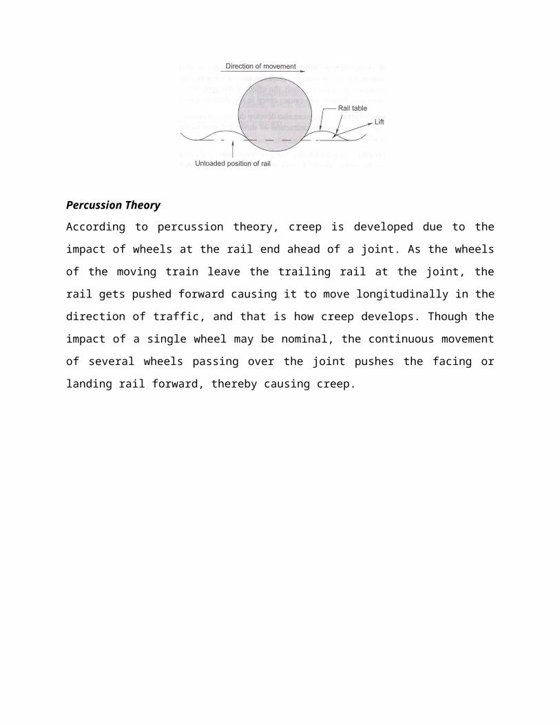
Fig. (a) Constituents of a turnout
Fig. (b) Left-hand turnout
Tongue rail It is a tapered movable rail, made of high-carbon or -manganese steel to withstand
wear. At its thicker end, it is attached to a running rail. A tongue rail is also called a switch rail.
Stockrail Itis the running rail against which a tongue rail operates.
Points or switch A pair of tongue and stock rails with the necessary connections and fittings
forms a switch.
Crossing It is a device introduced at the junction where two rails cross each other to permit the
wheel flange of a railway vehicle to pass from one track to another.

SWITCHES
A set of points or switches consists of the following main constituents (Fig. below).
Fig.Details of a switch
(a) A pair of stock rails, AB and CD, made of medium-manganesesteel.
(b) A pair of tongue rails, PQ and RS, also known as switch rails, made of medium-manganese
steel to withstand wear. The tongue rails are machined to a very thin section to obtain a snug fit
with the stock rail. The tapered end of the tongue rail is called the toe and the thicker end is
called theheel.
(c) A pair of heel blocks which hold the heel of the tongue rails is held at the standard clearance
or distance from the stockrails.
(d) A number of slide chairs to support the tongue rail and enable its movement towards or away
from the stockrail.
(e) Two or more stretcher bars connecting both the tongue rails close to the toe, for the purpose
of holding them at a fixed distance from eachother.
(f) A gauge tie plate to fix gauges and ensure correct gauge at thepoints.

Types of SwitchesSwitches are of two types, namely stud switch and split switch. In a stud type of switch, no separate tongue rail is provided and some portion of the track is moved from one side to the other side. Stud switches are no more in use on Indian Railways. They have been replaced by split switches. These consist of a pair of stock rails and a pair of tongue rails. Split switches may also be of two types—loose heel type and fixed heel type. These are discussed below.Loose heel type Fixed heel type
The toe of the switches may be of the following types.Undercut switch In this switch the foot of the stock rail is planned to accommodate the tongue rail (Fig. below).
Fig.Undercut switch
Overriding switch In this case, the stock rail occupies the full section and the tongue rail is planed to a 6 mm (0.25")-thick edge, which overrides the foot of the stock rail (Fig. below).
Fig.Overriding switch
Lecture-22
Introduction
POINT AND CROSSING-II
A tongue rail may be either straight or curved. Straight tongue rails have the advantage that they
are easily manufactured and can be used for right-hand as well as left-hand turnouts. However,
trains get jolted while negotiating with tongue rail turnouts because of the abrupt change in the
alignment. Straight rails are normally used for l-in-8.5 and l-in-12 turnouts on Indian Railways.
Curved tongue rails are shaped according to the curvature of the turnout ft the toe to the heel of
the switch. Curved tongue rails allow for smooth trains, but can only be used for the specific
curvature for which they are Curved switches are normally used for 1-in-16 and 1-in-20 IRS
(Indian Standard) turnouts on Indian Railways. Recently Indian Railways has also laying 1-in-
8.5 and 1-in-12 turnouts with curved switches on important li
Length of Tongue Rails
The length of a tongue rail from heel to toe varies with the gauge and the switch. The longer the
length of the tongue rail, the smoother the entry to the switch because of the smaller angle the
switch rail would make with the fixed heel divergence. The longer length of the tongue rail,
however, occupies too much layout space in station yards where a number of turnouts have to be
laid in space. The length of the tongue rail should be more than the rigid wheel a four-wheeled
wagon to preclude the possibility of derailment in case the move from their position when a train
is running on the switch. Table below the standard lengths of switches (tongue rails) for BG and
MG tracks.
Table: Length of tongue rail
Gauge and type Length of tongue rail (mm)
1-in-8.5 straight 1-in-12 straight 1-in-12 curved 1-in-16Curved
BG (90 R) 4725 6400 7730 9750 1.1150
MG (75 R) 4116* 5485* 6700* These dimensions hold good for NG tracks also.

CROSSING
A crossing or frog is a device introduced at the point where two gauge faces across each other to
permit the flanges of a railway vehicle to pass from one tract to another (Fig. below). To achieve
this objective, a gap is provided from the throw to the nose of the crossing, over which the
flanged wheel glides or jumps. In order to ensure that this flanged wheel negotiates the gap
properly and does not strike the nose, the other wheel is guided with the help of check rails. A
crossing consists of the following components, shown in Fig. below.
Fig.Details of a crossing
Fig.Point rail and splice rail
(a) Two rails, point rail and splice rail, which are machined to form a nose. Tic point rail ends at
thenose,whereasthesplicerailjoinsitalittlebehindthenose.Theoretically,thepointrail

should end in a point and be made as thin as possible, but such a knife edge of the point rail
would break off under the movement of traffic. The point rail, therefore, has its fine end slightly
cut off form a blunt nose, with a thickness of 6 mm (1/4"). The toe of the blunt nose is called the
actual nose of crossing (ANC) and the theoretical point where the gauge faces from both sides
intersect is called the theoretical nose of crossing (TNC). The 'V rail is planed to a depth of 6
mm (1/4") at the nose and runs out in 89 mm to stop a wheel running in the facing direction from
hitting the nose.
(b) Two wing rails consisting of a right-hand and a left-hand wing rail that converge to form a
throat and diverge again on either side of the nose. Wing rails are flared at the ends to facilitate
the entry and exit of the flanged wheel in thegap.
(c) A pair of check rails to guide the wheel flanges and provide a path for them, thereby
preventing them from moving sideways, which would otherwise may result in the wheel hitting
the nose of the crossing as it moves in the facingdirection.
Types of Crossings
A crossing may be of the following types.
(a) An acute angle crossing or 'V crossing
(b) An obtuse or diamondcrossing.
(c) A square crossing (Fig. below).
Fig.Square crossing also be classified as follows.
For manufacturing purposes, crossings can also be classified as follows.
Built-upcrossing
Cast steelcrossing
Combined rail and castcrossing
NUMBER AND ANGLE OF CROSSING
A crossing is designated either by the angle the gauge faces make with each other or, more
commonly, by the number of the crossing, represented by N. There are three methods of
measuring the number of a crossing, and the value of N also depends upon the method adopted.
All these methods are illustrated below.
Centre line method
This method is used in Britain and the US. In this method, N is measured along the centre line of
the crossing.
Right angle method
This method is used on Indian Railways. In this method, N is measured along the base of a right-
angled triangle. This method is also called Coles method.
Cot α/2 – N = N /1/2 or N = 1/2 Cot α/2
Cot α = N /1 or N = Cot α
Isosceles triangle method
In this method, N is taken as one of the equal sides of an isosceles triangle.
Sin α/2 = ½ /N or N = 1/2N
Cosec α/2 = 2N
N = ½ Cosec α/2
The right angle method used on Indian Railways, in which TV is the cotangent of the angle
formed by two gauge faces, gives the smallest angle for the same value of N.
To determine the number of a crossing-on site, the point where the offset gauge face of the
turnout track is 1 m is marked. The distance of this point (in metres) from the theoretical nose of
crossing gives N.

Lecture-23
Introduction
TURNOUTS
The simplest arrangement of points and crossing can be found on a turnout taking off from a
straight track. There are two standard methods prevalent for designing a turnout. These are the
(a) Coles method and (b) IRSmethod.
These methods are described in detail in the following sections.
The important terms used in describing the design of turnouts are defined as follows:
Curve lead (CL) This is the distance from the tangent point (T) to the theoretical nose of
crossing (TNC) measured along the length of .the main track.
Switch lead (SL) This is the distance from the tangent point (T) to the heel of the switch (TL)
measured along the length of the main track.
Lead of crossing (L) This is the distance measured along the length of the main track as follows:
Lead of crossing (L) = curve lead (CL) - switch lead (SL)
Gauge(G) This is the gauge of thetrack.
Heel divergence (d) This is the distance between the main line and the turnout side at the heel.
Angle of crossing (a) This is the angle between the main line and the tangent of the turnout line.
Radius of turnout (R) This is the radius of the turnout. It may be clarified that the radius of the
turnout is equal to the radius of the centre line of the turnout (/?,) plus half the gauge width.
R = R}+0.5,G
As the radius of a curve is quite large, for practical purposes, R may be taken to be equal to .ft,.
Special fittings with turnouts
Some of the special fittings required for use with turnouts are enumerated as follows:
Distance blocks Special types of distance blocks with fishing fit surfaces are provided at the
nose of the crossing to prevent any vertical movement between the wing rail and the nose of the
crossing.
Flat bearing plates As turnouts do not have any cant, flat bearing plates are provided under the
sleepers
Spherical washers These are special types of washers and consist of two pieces with a spherical
point of contact between them. This permits the two surfaces to lie at any angle to each other.

These washers are used for connecting two surfaces that are not parallel to one another.
Normally, tapered washers are necessary for connecting such surfaces. Spherical washers can
adjust to the uneven bearings of the head or nut of a bolt and so are used on all bolts in the heel
and the distance blocks behind the heel on the left-hand side of the track.
Slide chairs These are provided under tongue rails to allow them to move laterally. These are
different for ordinary switches and overriding switches.
Grade off chairs These are special chairs provided behind the heel of the switches to give a
suitable ramp to the tongue rail, which is raised by 6 mm at the heel.
Gauge tie platesThese are provided over the sleepers directly under the toe of the switches, and
under the nose of the crossing to ensure proper gauge at theselocations.
Stretcherbars These are provided to maintain the two tongue rails at an exactdistance.
Coles method
This is a method used for designing a turnout taking off from a straight track (Fig. 14.11). The
curvature begins from a point on the straight main track ahead of the toe of the switch at the
theoretical toe of switch (TTS) and ends at the theoretical nose of crossing (TNC). The heel of
the switch is located at the point where the offset of the curve is equal to the heel divergence.
Theoretically, there would be no kinks in this layout, had the tongue rail been curved as also the
wing rail up to the TNC. Since tongue rails and wing rails are not curved generally, there are the
following three kinks in thislayout.
Standard turnouts and permissible speeds

On Indian Railways, normally 1-in-8.5 turnouts are used for goods trains while 1-in-12 and 1-in-
16 turnouts are used for passenger trains. Recently 1-in-20 and 1 -in-24 turnouts have also been
designed by the RDSO, to be used to permit higher speeds for fast trains on the turnout side. The
maximum speeds permitted on these turnouts are given in Table below.
Table: Permissible speeds on turnouts
Gauge Type of
turnout
Switch angle Permissible speed (kmph)
BG 1 in 8.5 1°34'27" 10* for straight switch and 15 for curved switch for 52/60 kg
rails on PSC sleepers
BGf l-in-8.5 Symmetrical split
(SS) 0°27'35"
30forcurvedswitchaswellasSSwith52/60kgonPSC
sleepers; 15* for curved switch for 52/60 kg on PSCsleepers*
BG l-in-16 1°8'0" 0°24'27" 50 or 601
MG l-in-8.5 1°35'30" 0°29'14" 10 for straight as well as curved switch
MGf l-in-12 1°09'38" 0°24'27" 1 5 for straight switch and 1 5 for partly curved switch
MG l-in-16 0°24'27" 30

Lecture-24
DESIGN OF TURNOUTS
A turnout, after branching off from the main track, may run into various directions of which running parallel to the original track is most common. The design calculation of various turnout are based on following three factors:(i) Method of calculating variousleads
(ii) Method employed for crossingangle (iii)Type of tongue railused
Notation used in design calculationFollowing notation have been used in various methods for design ofturnouts: CL = Curvelead
= Distance between theoretical nose of the crossing (T.N.C.) and the tangent point ―T‖ measured along the length of main track.
SL = Switchlead= Distance between tangent point ―T‖ and the heel of the switch (H.S.) measured alongthe length of thetrack
L = Lead or crossinglead= Distance between T.N.C. and the heel of the switch (H.S.) measured along the length of the track
Lead rails, being curved rails, are not measured along their curve length, long their projected length along the straight rail.Therefore, CL, SL and L, it is clear thatCL = SL + L or L = CL - SLβ = Angle of the switch, i.e. the angle between the gauge faces of switch rail and stock rail α = Angle of the crossingd = Heel divergence or clearance R0 = Radius of the outer turnoutR = Radius of centre line of the turnout G = Gauge of the trackN = Number of the crossingD = Distance between T.N.C. and tangent point of crossing curve
Different method of the turnout design
Three methods are used for design of turnouts
Method-I
The important steps of this method are
(i) All three leads, CL, SL, and L are calculated. The CL and SL are particularly calculated
in thismethod.
(ii) Crossing angle (α) calculated using right anglemethod
(iii)Crossing curve is considered to start from an imaginary tangent point ahead of actualtoe
of the switch and end at T.N.C. This arrangement results formation of threekinks,
a) Kinks at the toe of the switch. Due to straight tonguerail.
b) Kink at heel of the switch. Due to non tangential of tongue rail to thecurve.
c) Kinks at toe of the crossing. Because the curve is carried theoretically upto T.N.C.but
crossing actually isstraight.
This design method all three kinds of kinks and was common in the past. But now a days used in
unimportant lines and sidings.
Design calculation of method I
Value of gauge (G), Heel divergence (d) and Angle of the crossing (α) are given
Curve lead (CL)
CL= 2GN
R-R adius
Hence R = R0 – G/2
R0 = 1.5G + 2GN2
SL =(2R0d)1/2 AS d2 is very small Comair to2R0d
Lead or crossing lead(L)
L = CL –SL
= G cot α/2 – (2 R0d)1/2 = (2 R0G)1/2– (2 R0d)1/2
= 2GN - (2 R0d)1/2
Heel Divergence (d)
From equation SL =(2R0d)1/2 d = (SL)2 / 2 R0

Method II
The important features of this method are
(i) Onlythecross lead―L‖iscalculated
(ii) The curve is tangential to the tongue rail. It springs up from heel of switch and ends at
T.N.C.
(iii)Out of three kinks, kinks formed at heel of the switch isremoved
This method was common in UK in past

Design Calculation
With given value of gauge (G), d, β (angle of switch) and α, the turnout is designed:
Lead or crossing lead (L):
L = (G - d)/ tan (α + β)/2 = (G - d) cot (α + β)/2
R-R adius:
R0 = (G – d) / 2 sin (α + β)/2 sin (α - β)/2 = (G – d) / (cot β - cot α)
and R = R0 –G/2
Method III
The important features of this method are
(i) This method is very similar to method II. But here the straight length at crossing is
provided.
(ii) So one end of the curve is tangential to tongue rail and spring up from the toe of the
crossing and is tangential to the straight length of thecrossing.
(iii)In this method kinks at toe of the switch and kinks at heel of the switch areremoved.
(iv)It is suitable where tongue rails and crossing are straight. This method permitsthe

Design Calculation
Let the straight length of the arms at crossing be x =T’C
R-Radius:
With given G, D, α, β and x
R0 = (G – d – x sin α)/(cos β – cosα)
R = R0 – G/2
Crossing Lead (L)
L = CN + NS = ON + T’P = x cos α + TP cot (𝛼+𝛽)2
L = x cos α + G’ cot (𝛼+𝛽) = x cos α + (G – d – x sin α) cot (𝛼+𝛽)2 2
d = x sin α - G – ((L– x cos α) / cot (𝛼+𝛽))2
To get value of method II put x =0

* Under revision
Lecture-25
Introduction
TRACK JUNCTION
Track junctions are formed by the combination of points and crossings. Their main objective is
to transfer rail vehicles from one track to another or to enable them to cross from one track to
another. Depending upon the requirements of traffic, there can be several types of track junctions
with simple track layouts. The most commonly used layouts are discussed in the following
sections.
TURNOUT OF SIMILAR FLEXURE
A turnout of similar flexure (Fig.) continues to run in the same direction as the main line curve
even after branching off from it. The degree of the turnout curve will be higher than that of the
main line curve. The degree and radius of the turnout curve are given by the formulae:
Fig Turnout of similar flexure
where Ds is the degree of the outer rail of the turnout curve from the straight track, Dmis the
degree of the rail of the main track on which the crossing lies, i.e., the inner rail in Fig. above, D t
is the degree of the rail of the turnout curve on which the crossing lies, i.e., the outer rail, Rsis the
radius of the outer rail of the turnout curve from the straight track, and .ft, is the radius of the rail
of the turnout curve on which the crossing lies, i.e., the outerrail.
TURNOUT OF CONTRARY FLEXURE
A turnout of contrary flexure (Fig. 15.2) takes off towards the direction opposite to that of the
main line curve. In this case, the degree and radius of the turnout curve are given by the
followingformulae:
Dt = Ds-Dm

* Under revision
Rt = RsRm/(Rm –Rs)
Here, Dmis the degree of the rail of the main track on which the crossing lies, i.e., the outer rail
in Fig.below.
Fig.Turnout of contrary flexure
SYMMETRICAL SPLIT
"Alien a straight track splits up in two different directions with equal radii, the layout is known
as a symmetrical split (Fig. below). In other words, a symmetrical spat is a contrary flexure in
which the radii of the two curves are thesame.
Fig.Symmetrical split
THREE-THROW SWITCH
In a three-throw arrangement, two turnouts take off from the same point of a main line track.
Three-throw switches are used in congested goods yards and at entry points to locomotive yards,
where there is much limitation of space. A three-throw switch has two switches and each switch
has two tongue rails placed side by side. There is a combined heel block for both the tongue rails
of the switch. The switches can be operated in such a way that movement is possible in three
different directions, that is, straight, to the right, and to the left. Three-throw switches are

* Under revision
obsolete now as they may prove to be hazardous, particularly at higher speeds, because the use of
double switches may lead to derailments.
Fig Three-throw switch (contraryflexure)
Fig.Three-throw switch (similar flexure)
DOUBLE TURNOUT
A double turnout or tandem is an improvement over a three-throw switch. In a double turnout,
turnouts are staggered and take off from the main line at two different places. This eliminates the
defects of a three-throw switch, as the heels of the two switches are kept at a certain distance
from each other. The distance between the two sets of switches should be adequate to allow
room for the usual throw of thepoint.
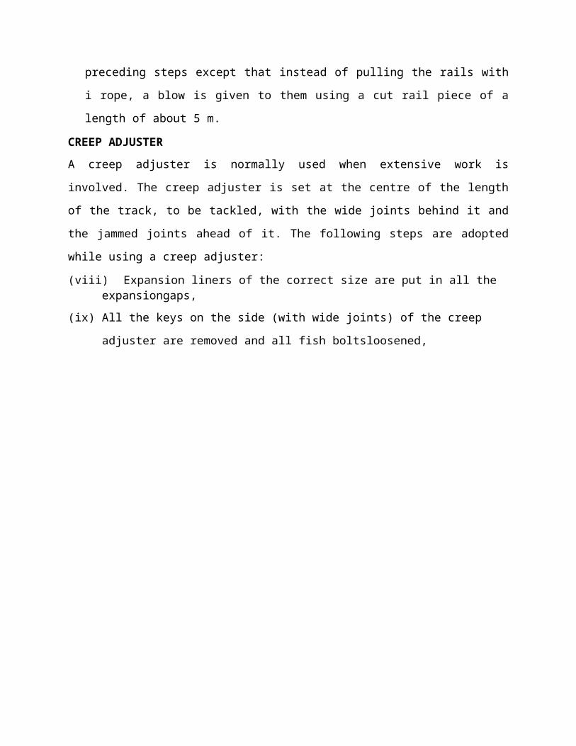
* Under revision
Fig.Double turnout with similarflexure
Fig.Double turnout with contraryflexure
Double turnouts are mostly used in congested areas, particularly where traffic is heavy, so as to
economize on space.
DIAMOND CROSSING
A diamond crossing is provided when two tracks of either the same gauge or of different gauges
cross each other. It consists of two acute crossings (A and C) and two obtuse crossings (B and
D).
Fig.Diamond crossing
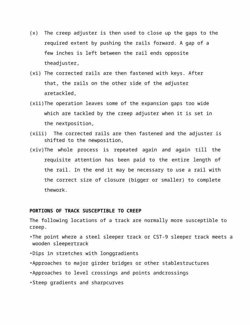
* Under revision
Single Slip and Double Slip
In a diamond crossing, the tracks cross each other, but the trains from either track cannot change
track. Slips are provided to allow vehicles to change track.
The slip arrangement can be either single slip or double slip. In single slips, there are two sets of
joints, the vehicle from only one direction can change tracks. In the single slip shown in Fig.
15.10, the train on track A can change to track D, whereas the train on track C remains on the
same track, continuing onto track D.
Fig.Single slip
In the case of double slips, there are four sets of points, and trains from both directions can
change tracks. In the double slip shown in Fig. the trains on both tracks A and C can move onto
either track B or D.
Fig. Doubleslip
SCISSORS CROSSOVER
A scissors crossover enables transferring a vehicle from one track to another track and vice
versa. It is provided where lack of space does not permit the provision of two separate
crossovers. It consists of four pairs of switches, six acute crossings, two obtuse crossings, check
rails,etc.

* Under revision
Fig.Scissors crossover
GAUNTLETTED TRACK
Gauntletted track is a temporary diversion provided on a double-line track to allow one of the
tracks to shift and pass through the other track. Both the tracks run together on the same sleepers.
It proves to be a useful connection when one side of a bridge on a double-line section is required
to be blocked for major repairs or rebuilding. The speciality of this layout is that there are two
crossings at the ends and no switches [(a)].
Fig. (a) Gauntletted track
Gauntletted tracks are also used on sections where trains have to operate on mixed gauges, say,
both BG and MG, for short stretches. In such cases, both the tracks are laid on the same set of
wooden sleepers [(b)].
Fig. (b) Gauntletted track for mixed gauge

* Under revision
GATHERING LINE
TRIANGLE
DOUBLE JUNCTIONS
A double junction (Fig. below) is required when two or more main line tracks are running and
other tracks are branching off from these main line tracks in the same direction. The layout of a
double junction consists of ordinary turnouts with one or more diamond crossings depending
upon the number of parallel tracks.
* Under revision
Fig. Doublejunction
Double junctions may occur either on straight or curved main lines and the branch lines may also
be either single or double lines. These types of junctions are quite common in congested yards.
* Under revision
Lecture-26
Introduction
SIGNAL-I
In the early days of railway operation, there was seldom need for more than one train to operate on a section of track at any given time. As traffic increased, it became necessary to operate trains in both directions over single track. The purpose of signalling and interlocking is primarily to control and regulate the movement of trains safely and efficiently. Signalling includes operations and interlocking of signals, points, block instruments, and other allied equipment in a predetermined manner for the safe and efficient running of trains. Signalling enables the movement of trains to be controlled in such a way that the existing tracks are utilized to the maximum.In fact, in railway terminology signalling is a medium of communication between the station master or the controller sitting in a remote place in the office and the loco pilot (As per latest instructions of the Railway Board, 'drivers' are now called 'Loco Pilots') of the train.OBJECTIVES OF SIGNALLINGThe objectives of signalling are as follows:To regulate the movement of trains so that they run safely at maximum permissible speeds To maintain a safe distance between trains those are running on the same line in the same directionTo ensure the safety of two or more trains that has to cross or approach each other To provide facilities for safe and efficient shuntingTo regulate the arrival and departure of trains from the station yardTo ensure the safety of the train at level crossings when the train is required to cross the path of road vehiclesCLASSIFICATION OF SIGNALSRailway signals can be classified based on different characteristics as presented in Table below.
Table: Classification of signals based on different characteristicsCharacteristics Basis of classification ExamplesOperational Communication of message in
visual formFixed signals
Functional Signaling the loco pilot to stop, move cautiously, proceed, orcarryout shunting operations
Stop signals, permissive Signals, shunt signals
Locational Reception or departure signals Reception: Outer, home, Departure:Starter, and advanced starter signals
Constructional Semaphore or colour light signals Semaphore: Lowerquadrant or upper quadrant. Colourlight: Two aspects or multiple aspects.
Specialcharacteristics
Meant for special purposes Calling-on signals, repeater signals, coaching signals,etc.

* Under revision
Figure.below shows further classification of signals and Table below lists the signallingrequirements of various classes ofstations.
Signals required atstationsClassification
of stationMinimum
requirementofsignals
Remarks
A class Warner, home, andstarter
An outer signal can be provided after obtaining specialpermission
B class Outer and home In multiple-aspect upper quadrant (MAUQ) areas, distant home and outer signals are provided
C class Warner and home In MAUQ areas, the warner signal is replaced by a distantsignal
FIXED SIGNALSThe various types of fixed signals used on railways are as follows.Semaphore signalsThe word 'semaphore' was first used by a Greek historian. 'Sema' means sign and 'phor' means to bear. A semaphore signal consists of a movable arm pivoted on a vertical post through a horizontal pin as shown in Fig. below.

* Under revision
Fig.Semaphore signal
Lower quadrant semaphore signals move only in the fourth quadrant of a circle and have only two colour aspects. In order to provide the drivers with further information, multi-aspect upper quadrant signalling (MAUQ) is sometimes used on busy routes. In this system, the arms of the semaphore signals rest in three positions and the signals have three colour aspects, namely red, yellow, and green associated with the horizontal, 45° above horizontal and vertical directions, respectively. Details of MAUQ are given in subsequent paras.
Stop signal in MAUQ, SignalingIn case of multi-aspect upper quadrant (MAUQ) signaling of semaphore stop signal with a square ended arm, there may be three situations (Figure below) as indicated below in Table below:
Fig. Semaphore stop signal in MAUQsignaling

* Under revision
Table Aspects and indications of stop signal in MAUQ signalingPosition Aspect of signal Position of
armColour during night Indication
1. ON-Stop Horizontal Red Stop dead2. OFF-Caution 45° above
HorizontalYellow Proceed with caution andbe
prepared to stop at nextsignal3. OFF-Proceed 90° above
HorizontalGreen Proceed at maximum
permitted speed
The signals are designed to be fail-safe so that if there is any failure in the working of the
equipment, they will always be in the stop position. These signals are operated by hand levers or
buttons located in a central cabin, which is normally provided near the station master's office.
Semaphore stop signals are normally provided as outer signals, home signals, starter signals,
advanced starter signals, and warner signals.
Permissive signal—warner or distant signal
In order to ensure that trains speed up safely, it is considered necessary that warning be given to
drivers before they approach a stop signal. This advance warning is considered necessary,
otherwise the drivers may confront a 'stop signal' when they least expect it and take abrupt
action, which can lead to perilous situations. A warner or distant signal has, therefore, been
developed, which is to be used ahead of a stop signal and is in the form of a permissive signal
that can be passed even in most restricted conditions. In the case of a stop signal, the driver has
to stop the train when it is in the 'on' position, but in the case of a permissive signal, the driver
can pass through even when it is in the 'on'position.
Distant signal in MAUQ, signaling
In case of multi-aspect upper quadrant (MAUQ) signaling for semaphore distant signal, there is a
fish tailed arm, painted yellow with a black band near the edge of the arm (Fig. below). There are
three aspects and indications of the same are presented in Table below.

* Under revision
Fig. Semaphore distant signal in MAUQ signaling
Table Aspects and indications of distant semaphore signal in MAUQ signalingCase Aspect of
signalPosition ofarms
Colour during night Indications
A ON —Caution
Horizontal Yellow light Proceed and be prepared to stopat next stop signal.
B OFF 45°abovehorizontal
Two yellow lightsin vertical alignment
Proceed and be prepared to passthe next signal at caution.
C OFF—Proceed
90°abovehorizontal
Green light Proceed at maximum permittedspeed.
In the case of signaling using colored light, the permissive signal is distinguished from the stop
signal by the provision of a P marker disc on the signal post.
The warner signal is intended to warn the driver of a train regarding the following aspects as
explained in Table below.
(a) To inform that the driver is approaching a stopsignal
(b) To inform the driver as to whether the approach signal is in 'on' or 'off position
The warner signal can be placed at either one of the followinglocations.
(a) Independently on a post with a fixed green light 1.5 m to 2 m above it for nightindication
(b) On the same post below the outer signal or the homesignal
In case a warner is fixed below an outer signal the various positions of the outer and warner
signals and their corresponding indications are given in Fig. below.

* Under revision
Table: Position of warner arm or distant signalPosition Day indication for
semaphore signalNight indication for semaphore signal*
Aspect
Caution Arm horizontal Red light Yellow light Proceed with caution and be prepared to stop at the next stop signal
Attention Arm inclined 45° in the upward direction
Two yellow lights Proceed cautiously so as to pass the next stop signal at a restricted speed
Proceed Arm inclined 90° in the upward or 45° in thedownward direction
Two green lights Proceed at full permissible speed

* Under revision
Lecture-27
SIGNAL-II
STOP SIGNALS
The various types of stop signals with reference to their location on a station are discussed here
in detail.
Outer signal on double-line section
This is the first semaphore stop signal at a station that indicates the entry of a train from a block
section into the station limits. This signal is provided at an adequate distance beyond the station
limits so that the line is not obstructed once the permission to approach has been given. It is
provided at a distance of about 400 m from the home signal. The signal has one arm but has a
warner signal nearly 2 m below on the same post.
Home signal on double-line section
After the outer signal, the next stop signal towards the station side is a home signal. It is provided
right at the entrance of the station for the protection of the station limits. The signal is provided
about 50 m short of the points and crossings. The arms provided on a home signal are generally
as many as the number of reception lines in the station yard. The signal for the main line is
provided on a 'doll', which is higher than others.
Routing signal
The various signals fixed on the same vertical post for both main and branch lines are known as
routing signals. These signals indicate the route that has been earmarked for the reception of the
train. Generally, the signal for the main line is kept at a higher level than that for the loop line. It
is necessary for the driver of a train approaching a reception signal to know the line on which his
or her train is likely to be received so that he or she can regulate th speed of the train
accordingly. In case the train is being received on the loop li 3, the speed has to be restricted to
about 15 km per hour, whereas if the reception s on the main line, a higher speed is permissible.
Signaling arrangement under Modified Lower Quadrant SignalingSystem
Since lower quadrant semaphore two aspect signaling system is capable of conveying limited
information to the loco pilot, the arrangement was modified to be known as Modified Lower

* Under revision
Quadrant Signaling. In this an arrangement a warner is provided on the same doll as that of
mainline home signal. see Fig. below.
Fig.Modified lower quadrant signaling arrangement
Route indicators can also be provided by including separate home signals foi each line, with the
main line home signal being placed the highest while all the other signals are placed at the same
level.
In the case of coloured light signals, the home signal is provided with either a graphic lighted
route indicator displaying the line number on which the train is to be received or different arms
lighted by five lamps. These lamps form the arm. which is used for indicating a line, while there
is no arm in the case of a main line as depicted in Fig. below.
* Under revision
Starter signal
The starter signal is a stop signal and marks the limit upto which a particular line can be
occupied without infringing on other lines. A separate starter signal is provided for each line.
The starter signal controls the movement of the train when it departs from the station. The train
leaves the station only when the starter signal is in the 'off position. As this signal controls the
departure of a train, it comes under the category of departuresignals.
Fig. Route indicators in semaphore and colour light signallingareas
Advanced starter signal
This is the last stop signal provided for the departure of trains from a station. The signal is
provided beyond the outermost points or switches and marks the end of the station limits. A
block section lies between the advanced starter signal of one station and the outer signal of the
next station. No train can leave the station limits until and unless the advance starter is taken off.
SIGNALLINGSYSTEMS
The signalling system can be broadly classified into two main categories.
(a) Mechanical signallingsystem
(b) Electrical signallingsystem
In addition to these two main categories of signalling systems, electronic or solid-state signalling
system is also in use. Each system of signalling comprises five main components.

* Under revision
(a) Operated units such as signals and points
(b) Interlockingsystem
(c) A transmission system such as single- or double-wire transmission or electrical transmission
throughcables
(d) Operating units such as levers and press buttons
(e) Monitoring units such as detectors, treadle bars, and trackcircuits
The comparison between mechanical and electrical signalling based on these five broad
components is given in Table below.
Table :Comparison of signalling systemsComponent Mechanical ElectricalOperated units signals
Mechanically operated signals as per lower quadrant or upper quadrant andmodified lower quadrant signalling
Coloured light signals with two- aspect, three-aspect or four-aspect signalling
Points Mechanically operated points; locking with the help of point locks, stretcher bars, and detectors
Electrically operated points (by converting the rotary movement of electric motors into linear push or pull); locking with the helpofslides and solid rods
Level crossing gates
Interlocking of manually operated swing leaf gate or operation and Interlocking of mechanicallyoperatedlifting barriers
Operation and Interlocking of electrically operated lifting barriers
Transmission systems
Single or double wire transmissionto the requisite points by means of rods ordouble wires
Electrical transmission through overhead wires or underground cables
Operating units
Hand levers with a range of 500 to 2000 m used in collaboration with single wireor double wire lever frames
Push buttons, rotary switches, or electrical signalling equipment
Interlocking units
Mechanical interlocking with plungers attached with levers and tappets movingacross in a locking trough
Interlocking through electromagnetic switches known as relays orsolid-stateswitching devices
Monitoring units
Monitoring of points with the help of mechanical detectors; monitoring of the passage of trains using a treadle, whichis an electro-mechanical device
Monitoring with the help of direct current track circuits, alternating current track circuits, electronic track circuits, axlecounters, etc.

* Under revision
MECHANICAL SIGNALLING SYSTEMThe mechanical signalling system mostly involves signals and points as explained in thissection.
In this system, both the signalling system and the interlocking are managedmechanically.
Signals
The signals used in a mechanical signalling system are semaphore signals. These signals are
operated by means of either a lower quadrant or an upper quadrant signalling system.
Lower quadrant signalling system
This system of signalling was designed so that the semaphore arm of the signal could be kept
either horizontal or lowered. The lower left-hand quadrant of a circle is used for displaying a
semaphore indication to the driver of a train. This concept was possibly developed based on the
left-hand driving rules applicable on the roads in UK and India.
Upper quadrant signalling system
In lower quadrant signalling, the semaphore arm of the signal can only take two positions,
namely horizontal or lower; it is not possible to include a third position for the semaphore arm,
such as a vertically downward position due to design as well as visibility problems, since as the
semaphore arm would, in that case, be superimposed on the signal post. Due to this limitation,
the upper quadrant system (see Table 31.10) was developed, which can display more than two
aspects. In this system, it is possible to incorporate three positions of the semaphore arm,namely
(a) horizontal, (b) inclined at an angle of about 45° above the horizontal level, and (c) vertical,
i.e., inclined at an angle of 90° above the horizontal level, see Fig. below. The positions of the
arm, the corresponding indications, and their meanings are listed in Table below.
Fig. Upper Quadrantsignalling

* Under revision
Lecture-28
SIGNAL-III
COLOURED LIGHT SIGNALSThese signals use coloured lights to indicate track conditions to the driver both during the day
and the night. In order to ensure good visibility of these light signals, particularly during
daytime, the light emission of an electric 12 V, 33 W lamp is passed through a combination of
lenses in such a way that a parallel beam of focused light is emitted out. This light is protected by
special lenses and hoods and can be distinctly seen even in the brightest sunlight. The lights are
fixed on a vertical post in such a way that they are in line with the driver's eye level. The system
of interlocking is so arranged that only one aspect is displayed at a time. Coloured light signals
are normally used in automatic signalling sections, suburban sections, and sections with a high
traffic density
Coloured light signals can be of the following types.
(a) Two-aspect, namely green andred
(b) Three-aspect, namely green, yellow, andred
(c) Four-aspect, namely green, double yellow, andred
In India, mostly three-aspect or four-aspect coloured light signalling is used. In the case of three-
aspect signalling, green, yellow, and red lights are used. Green indicates 'proceed', yellow
indicates 'proceed with caution', and red indicates 'stop'(Fig. below).
Fig.Colored light signals
* Under revision
In the case of four-aspect colored light signaling, the interpretations of the colours are given in
Table below.
Table: Indications of colored light signalsColour of signal InterpretationRed Stop deadYellow Pass the signal cautiously and be prepared to stop at the next signalTwo yellowlights
Pass the signal at full speed but be prepared to pass the next displayedtogether signal, which is likely to be yellow, at a cautiousspeed
Green Pass the signal at full permissive speed
In conventional semaphore signals, the 'on' position is the normal position of the signal and the
signals are lowered to the 'off' position only when a train is due. In the case of coloured light
signals placed in territories with automatic signalling, the signal is a\way green or in the 'proceed'
position. As soon as a train enters a section, the signal changes to 'red' or the 'stop' position,
which is controlled automatically by the passage of the train itself. As the train passes through
the block section, the signal turns yellow to indicate the driver to 'proceed with caution' and,
finally, when the train moves onto the next block section, the signal turns green indicating to the
driver to 'proceed at full permissible speed'.
Thus, it can be seen that each aspect of the signal gives two pieces of information to the driver.
The first is about the signal itself and the second is about the condition of the track ahead or of
the next signal. This helps the driver to manoeuvre the train safely and with confidence even at
the maximum permissiblespeed.
Calling-on signal
This consists of a small arm fixed on a home signal post below the main semaphore arm. When
the main home signal is in the horizontal (on) position and the calling-on signal is in an inclined
(off) position, it indicates that the train is permitted to proceed cautiously on the line till it comes
across the next stop signal. Thus, the calling-on signal is meant to 'call' the train, which is waiting
beyond the homesignal.

* Under revision
Fig.Calling-on signal
The calling-on signal is useful when the main signal fails, and in order to move a train, an
authority letter has to be sent to the driver of the waiting train to instruct him/her to proceed to
the station against what is indicated by the signal. In big stations and yards, the stop signals may
be situated far off from the cabin and the calling-on signal expedites the quick reception of the
train even when the signal isdefective.
Co-acting signal
In case a signal is not visible to the driver due to the presence of some obstruction, such as an
overbridge or a high structure, another signal is used to move along the main signal on the same
post. This signal, known as the co-acting signal, is an exact replica of the original signal and
works in unison with it.
Repeatersignal
In case where a signal is not visible to the driver from an adequate distance due to sharp
curvature or any other reason or where the signal is not visible to the guard of the train from his
position at the rear end of a platform, a repeater signal is provided at a suitable position at the
rear of the main signal. A repeater signal is provided with an R marker and can be of the
followingtypes.
(a) A square-ended semaphore arm with a yellow background and a black verticalband
(b) A colored light repeatersignal
(c) A rotary or disc banner typesignal
The 'off positions of these three types of repeater signals are depicted in Fig. below.
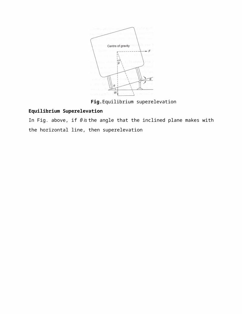
* Under revision
Fig.Different types of repeater signals
Shunt signals
These are dwarf or miniature signals and are mostly used for regulating the shunting of vehicles
in station yards. Unlike fixed signals, these are small in size and are placed on an independent
post or on a running signal post (Fig. below). In semaphore signaling areas, the shunt signals are
of the disc type.
Fig.Disc type shunt signals

* Under revision
Point indicators
These are used to indicate whether points have been set for the main line or turnout side (Fig.
below). It essentially consists of an open box with two white circular discs forming two opposite
sides of the box and green bands on the other two remaining sides. The box rotates automatically
about a vertical axis with the movement of the points. The white disc indicates that the points are
set for the main line. When the points are set for the turnout side, the green bands are visible to
the loco pilot (driver). At night white light indicates a main line setting and green light signifies a
turnout side settings.
Fig. Pointindicators

* Under revision
Trap indicator
A trap is a device fitted on the track, which in its open position derails the vehicle that passes
over it. When the trap is closed, the vehicle passes over it as it would over a normal track. A trap
indicator reveals whether the trap is in an 'open' or 'closed' position. The details of the same are
given in Table below.
Table Operation of a trap indicatorPosition of trap Day indication Night indication
Trap open Red target Red lightTrap closed Green target Green light
Dock signal This signal leads the train to the dock platform. In this case, the semaphore
reception signal is provided with a stencil-cut letter 'D' on the signal for use. Figure (a) below
shows the 'on' position of the docksignal.
Fig. (a) Dock signal (on position) and (b) Goods signal (onposition)
Goods signal This signal leads the train to the goods running line. In this case a stencil-cut letter
'O' is provided on the signal arm of a semaphore signal as shown in Fig. (b) above.
Engineering indicators
When the track is under repair, trains are required to proceed with caution at restricted speeds
and may even have to stop. Caution indicators help the driver of a train to reduce the speed of (or
even stop) the train at the affected portion of the track and then return it to the normal speed once
that portion has beencovered.

* Under revision
Sighting board
A sighting board (Fig. below) is an indication to the Loco pilot (driver) that he or she is
approaching the first stop signal of a railway station. The function of a sighting board is to allow
the driver to estimate the location of the next stop signal from the current location so that he/she
starts applying brakes in case the first stop signal is in an 'on' position.
Fig. Sightingboard
As the requisite braking distance of goods trains and Rajdhani trains is greater than that of the
passenger trains, the sighting boards for goods trains and Rajdhani trains are located farther and
their design is different from that of sighting boards meant for passenger trains. The distances of
sighting boards are listed in Table below.
Table :Positions of sighting boardsType of sighting board PositionPassenger train sighting board 1000 m for speeds over 72 kmph for BG tracks
and 48 kmph for MG tracksGoods trains and Rajdhani sighting board 1400 m for speeds over 72 kmph for BG tracks
and 48 kmph for MG tracks

* Under revision
Lecture-29
PRINCIPLES OF INTERLOCKING-I
Points
Points are set mechanically and are kept in locks and stretcher bars. The mechanical arrangement
for operating them includes a solid rod with a diameter of 33 mm running from the lever
provided in the cabin and connected to the point through cranks and compensators. Owing to
transmission losses, the operating points with rods is restricted to a specified distance from the
cabin.
The following devices are used to ensure that the points are held rigidly in the last operated
position under a moving train and to ensure absolute integrity of the same.
(a) Point locks to hold the point in the required position and to rigidly hold the point in the
position of the lastoperation
(b) Facing point lock with lock bars to prevent the movement of points when a train is passing
overthem
Point locks
A point lock is provided to ensure that each point is set correctly. It is provided between two
tongue rails and near the toe of the switch assembly. The point lock consists of a plunger, which
moves in a plunger casing of facing point lock. The plunger is worked by means of a plunger
rod, which is connected to the signal cabin through a lock bar. Additionally, there is a set of
stretcher blades and each blade is connected to one of the tongue rails. Each blade has two
notches and they move inside the facing point lock plunger casing along with the tongue rails.
When the points are set correctly for a particular route, the notch in the stretcher blade rests in its
proper position and the plunger rod enters the notch, locking the switch in the last operated
position.
Detectors
Detectors are normally provided for all the points for the following reasons.
(a) To detect any defect or failure in the connection between the points and the lever as well as
any obstruction between the stock and the tonguerail.
(b) To ensure that the correct signal, which corresponds to the point set, islowered.

* Under revision
(c) Adetector can be mechanical or electrical. In the case of a mechanical detector, the point is
held in the position of the last operation, which is achieved de facto by virtue of its design.
However, it cannot be considered as a device to keep the pointlocked.
A detector normally consists of a detector box, which is provided with one slide for points and
another set of slides for signals. The signal slides are perpendicular to the point slides. The slides
are held suitably and no vertical movement of the same is possible. The signal slide has only one
notch whereas the point slide has a number of notches depending upon the number of signals
relevant to the points. The detector works on the principle that a particular signal can be lowered
when the notch in that particular signal slide coincides with the notch in the point slide. For
example, if the points are correctly set for the main line, the point slide moves and its notch
comes to rest opposite the notch of the main line signal slide. The main line signal slide can then
be pulled and the main line signal lowered. It may be noted here that the point slide will move
and its notch will rest in its correct position only if the points are properly set and there is no
obstruction in between.
The linear type (or slide type) of mechanical detector is used for single-wire signalling (Fig. a
below), whereas the rotary type of detector (Fig. b below) is used for the double-wire signalling.
A double-wheel detector is a rotary-type detector that rotates in a vertical plane. It detects the
correct setting of points and, in addition, locks the points in the last operated position in the case
of wire breakage.
Fig. a Mechanical detector for single-wire signalling
* Under revision
Fig. b Double-wheel rotary detector
Lock bar
A lock bar is provided to make it impossible to change the point when a train is passing over it.
The lock bar is made of an angled section and its length is greater than that of the longest wheel
base of a vehicle. Short revolving clips are provided to hold the lock bar in place on the inside
face of one of the rails. The length of a lock bar is normally 12.8 m for BG and 12.2 m for MG
sections. The system is so designed that when the lever in the cabin is pulled to operate the
locking device, the lock bar risesslightlv above the rail level and then comes down. In the
occurrence that a vehicle is positioned on the same location, the lock bar cannot rise above the
rail level due to the flanges of the wheel and as such the point cannot be operated.
Types of Transmission Systems
A signal is operated by pulling the associated lever and this action is transmitted through a
single-wire or double-wire system. Initially, the single-wire system was the most popular way of
operating signals and, in fact, some stations on Indian railways still use this system.In the single-
wire system, only one wire is stretched between the operating lever and the signal, whereas in the
double-wire system a loop of two wires that run parallel to each other is wrapped over a drum
lever and this system works on the principle of the pull and push arrangement.
Single-wiretransmission
Leverframe
Signal transmission wire
Cabin wireadjuster
Signal parts andfitting
Limitations of single-wiresignaling
* Under revision
Rod transmission In the single-wire transmission system, the signal is lowered or set in the 'off'
position by pulling the lever. The signal returns to the 'on' position due to the effect of gravity as
soon as the lever is restored to its normal position and the tension in the wire is released.
Where the operation of points is concerned, the points have to be set in either the normal or the
reverse position; one of these positions can be attained through pulling and the other by pushing.
Solid rods of 30 mm (11/4 ") diameter are used to connect the levers to the points. The rods or
pipes move on standard roller guides fixed at about 2 m (6 ft) intervals. A suitable crank is also
used at every change of direction. The rods are subjected to expansion and contraction due to
temperature variations and as such are provided with rod compensators at designed intervals.
Rod temperature compensator
A rod compensator, also known as a temperature compensator, is provided to neutralize the
effect of thermal variations. It consists of a pair of cranks—one acute and one obtuse—
connected by a link and is so designed that it absorbs the expansion or contraction due to
temperature variations. The compensator is normally placed at the centre of the rod upto a length
of 36.5m. If more than one compensator is required, these are placed at quarterpoints.
As can be seen in Fig. below, the points, A or B may move left or right, but the total distance
between them remains the same.
Fig.Temperature compensator
Double-wire transmission system
In this system, power is transmitted with the help of two wires from the lever to operated units,
such as signals, points, locks, detectors, and so on. Each wire consists of eight to ten SWG solid
galvanized steel wires attached to pulley stakes, which are driven firmly into the ground. The
twowiresareconnectedbetweentheleverandthesignaltoformacontinuousloop.Whenthe
* Under revision
lever is operated, it leads to the wire getting pulled and when the lever is brought back to its
normal position, it results in a push to the wire. This pull and push mechanism (Fig. a below)
causes the drum to rotate in one direction when the lever is pulled and in the other direction
when it is restored to its normal position. The rotary motion of the drum is then converted into
linear movement by the use of cams and cranks and this finally actuates the signal. Figure b
below shows the complete double-wire transmissionsystem.
It may be brought out that double-wire compensators are provided in the wire run to always keep
the same tension in the wire.
Fig: a Double wire mechanism
Fig: b Double wire Transmission system
Table below compares a signal-wire and a double-wire signalling system. The special features of
a double-wire signalling system are as follows.
* Under revision
ELECTRICAL SIGNALLING SYSTEM
The electrical signalling system is progressively replacing the mechanical signalling system on
Indian Railways, especially with the coming up of railway electrification projects facilitating
availability of electric power reading. The main reasons behind this are as follows.
(a) There are a number of movable parts in the mechanical signalling system, such as rods, wires,
and cranks, which cause heavy wear and tear, frictional losses, and many of these parts can be
sabotaged by unauthorizedpersons.
(b) The arms of the semaphore signals used in mechanical signalling afford poor visibility during
the day. The night indications of these signals are also notsatisfactory.
(c) The operational time of the mechanical signalling system is much greater than that of the
electrical signallingsystem.
In the electrical signalling system, electrical energy is used for displaying signal aspects. The
transmission of power is done electrically and the units are operated by electrical push buttons
while the system is monitored by electrical systems. The interlocking in this system is also done
electrically.
In the case of electronic or solid state signalling system, the signals are operated by the electrical
method, but the interlocking is done electronically.
System of electronic interlocking For electronically managed interlocking system a computer
and mouse is used for controlling the signalling system; however, a panel is also used with a
switch to change the mode of control from a panel to a visual display unit (VDU).
As control of the signalling system is carried out by a VDU and a mouse, the portion of the
signal and interlocking plan shall be selected for taking off the concerned signal by clicking onto
the signal profile on the VDU. The system shall work within, following the same principles as in
case of electrically interlocked system but analyse the requirements electronically and energize
the relays in the form of the final command to operate points and make the concerned signal off.
OperatedUnits
The operated units consist of signals and points. The electrical signalling system consists of
either coloured light signals or signals with semaphore arms operated by electricmotors.
A point is operated by converting the rotary movement of the electrical point machines fastened
on the sleepers near the point into a linear push or pull force. There are low-voltage point
machines operated with a 24 V dc supply and high-voltage point machines operated using a 110

* Under revision
V dc supply. The operation of a point machine involves first unlocking the lock, bringing the
point from normal to reverse or reverse to normal as the case may be, and then locking the point
once again. The operating time of these point machines varies between three and five seconds.
Transmission Medium
The medium of transmission for operating electrical equipment is either an overhead alignment
or an underground copper cable. The overhead alignment is used when the number of conductors
is limited. In areas provided with 25 kV ac traction, it is not possible to use overhead alignments
due to the induced electromotive force (EMF) generated as a result of electrostatic and
electromagnetic induction. In big yards, cables are used as a medium of transmission for the
operation of point machines. The cables are either hung on hooks and run by the side of the track
or laid underground. In areas provided with ac traction, underground screened cables areused.
Operating System
Normally push buttons and rotary switches are used for operating signalling equipment that work
on electricity. The complete yard layout is represented on the face of a console. Signals, tracks,
points, and the gates of level crossings are depicted in their geographical positions on this
console and the positions of these switches are then marked at the foot of signals and on various
tracks.
Complete interlocking is achieved through electromagnetic switches known as relays. The two
methods of interlocking available are panel interlocking or route relay interlocking.
Pressing of two buttons on the operating console checks clearance of route; if found clear, sets
the route by operating points automatically by the system and then locks the route, takes the
concerned signal off. This is known as route relay interlocking, often called on smaller stations
as 'panel interlocking' as amisnomer.
Monitoring System
A monitoring system mainly consists of point detectors, track circuits, and axle counters, all of
which are discussed here in detail.
Electrical point detector
The electrical point detector detects and ensures that points are properly set. It also works on a
'slide system' as used in the mechanical system. These slides are so adjusted that a gap of 3 mm
is left between the switch rail and the stock rail so that the two do not come in contact and,
therefore, it is not possible to turn the signal off at anytime.

Trackcircuit
The track circuit is an electric circuit formed along with the running rails and connected to the
signal and cabin. Its function is to indicate the presence of a train (or vehicle) on the track. In
order to set up a track circuit, the ends of the rails forming the circuit are isolated by insulating
the railjoints.
The various types of track circuits used on the Railways are as follows.
(a) Direct current trackcircuit
(b) Alternating current trackcircuit
(c) Electronic track circuit, which are audio-frequency trackcircuits
Axle counters
As already mentioned, two consecutive rails need to be insulated from each other for setting up a
track circuit. A pair of rail inductors are installed at either end of the track for counting the axles.
As soon as a train enters the track section from one end, the number of axles entering the section
are counted automatically. Similarly, when the train leaves the track section at the other end, the
axles are counted once again at the other end.

* Under revision
Lecture-30
PRINCIPLES OF INTERLOCKING-II
INTERLOCKING
Interlocking is a device or a system meant to ensure the safety of trains. With the increase in the
number of points and the signals and introduction of high speeds, it has become necessary to
eliminate human error, which would otherwise lead to massive losses of life and property. The
points and signals are set in such a way that the cabin man cannot lower the signal for the
reception of a train unless the corresponding points have been set and locked. The signal is thus
interlocked with the points in a way that no conflicting movement is possible and the safety of
trains is ensured. Interlocking may therefore, be defined as a technique, achieved through
mechanical or electrical means by which it is ensured that before a signal is taken 'off, the route
which the signal controls is properly set, locked and held till such time the entire route is
traversed by the train and at the same time all the signals and points, the operation of which
would lead to conflicting movements, are locked against the feasibility of such conflicting
movements.
The signal and interlocking system is so designed that the failure of any equipment results in the
turning 'on' of the signal, thus ensuring train safety.
Essentials of Interlocking
Lever frames and other types of equipment provided for the operation and control of signals,
points, etc., must be so interlocked and arranged as to comply with the following essential
regulations:
(a) It should not be possible to turn a signal off unless all points for the line on which the train is
to be received are correctly set, all the facing points are locked, and all interlocked level
crossings are closed and inaccessible to roadtraffic.
(b) The line should be fully isolated before the signal is turned off, i.e., no loose wagons should
be able to enter thisline.
(c) After the signal has been taken off, it should not be possible to make adjustments in the
points or locks on the route, including those in the isolated line. Also, no interlocked gates
should, be released until the signal is replaced to the 'on'position

* Under revision
(d) It should not be possible to turn any two signals off at the same time, which can lead to
conflicting movements of thetrains.
(e) Wherever feasible, the points should be so interlocked as to avoid any conflicting
movement.
Standards of Interlocking
The speed of a train depends on a number of factors such as the haulage capacity of the
locomotive, the fitness of the track, the fitness of the rolling stock, the load of the train, the ruling
gradient and standard to which the signalling system is provided.
Signaling arrangements
The signalling equipment, manner of locking points, and operation of signals and points differ in
the different standards of interlocking. The types of signalling equipment to be provided at
different interlocked stations and other requirements to be met for each of the four categories do
differ.
Locking of points
The method of locking of points is the key locking in Standard-I. It is an indirect method of
interlocking between signals and points. In Standard-II, a plunger type facing point lock is used.
The plunger lock can be operated from the cabin or from the site itself. In standard-Ill and IV, the
points are to be centrally operated and the locking between points and signals is required to be
direct.
Isolation of lines
In Standard-I, isolation is optional. In Standards II, III, and IV, the main line musl be isolated
from all the adjoining lines.
Details of signalling as well as of interlocking for different interlocked stations, viz., Standard I,
Standard II, Standard III, and Standard IV are briefly summarized in Table below.
Methods of Interlocking
There are basically two methods of interlocking as explained below.
Key interlocking
Key interlocking is the simplest method of interlocking and still exists on branch lines of small
stations on Indian Railways. The method involves the manipulation of keys in one form or the
other. This type of interlocking is normally provided with standard interlocking with a speed
* Under revision
limit below 50 km per hour. The simplest arrangement of key interlocking is accomplished in the
following manner.
(a) Take the example of a station with a main line and a loop line, the point can be set either for
the main line or branchline.
(b) The point has two keys, the first is key A, which can be taken out when the point is set and
locked for the main line. Similarly, key B can be taken out when the point is set and locked for
the loop line. At any given time either key A or key B can be taken out, depending upon whether
the route is set for the main line or the loopline.
(c) The lever frame operating the signals is provided with two levers. The lever concerning the
main line signal can be operated only by key A and similarly the loop line signal lever can be
operated only by keyB.
(d) If the train is to be received on the main line, the points are set and locked for the main line
and key A is released. This key is used for interlocking the main line signal lever, thus lowering
the signal for the main line. Since key A cannot be used for interlocking and lowering the loop
line signal, only the appropriate signal can be taken off. This type of interlocking is called
indirectlocking.
Mechanical system of interlocking
Almost 70 per cent of railway stations in the country work with the mechanical system of
signalling. The interlocking arrangements for mechanical signalling system have to be
mechanically oriented. There are two systems of mechanically designed signals: (i) single-wire
system and the (ii) double-wire system.
A mechanically structured signal has (i) spectacle with an arm; (ii) signal post, which may be
tubular or lattice. Longer posts are chosen to be lattice; and (iii) a counterweight to help pull the
wire back to allow the signal to go back to its on/normal position.
Such mechanical structures of signals are: (i) two-aspect semaphore signal and (ii) multiple-
aspect semaphore signal.
Mechanical interlocking or interlocking on lever frames is an improved form of interlocking
comtmred to key locking.
Electrical system of interlocking
As the signal displays fixed light illuminated by incandescent lamp or a light emitting diode
(LED) signal, the operation of such system may be through mechanically operated levers or by
push buttons provided on the yard layout depicted on the top of panel box to be termed as the
control cum indication panel. Under the electrical signalling system the colour light signals are
used in any case operated by lever, points (i) operated by wrought iron solid 33 mm rod; (ii)
operated by electric point machines, or operated by Control cum Indication Panel operating
points by an electric point machine with signals being coloured light. The system of operation of
electrically operated signals by levers is hybrid and is invariable an interim measure to suit 25
kV ac traction, to be subsequently converted to oepration by control-cum-indicationpanel.
Typical Cases of Interlocking
The following typical cases of interlocking are usually encountered.
Normal locking In this case, pulling one lever locks the other lever in its normal position. Such
locking shall be required in situation like the signal lever locking a point lever, when the signal
requires the point to be moved for train movement.
Back locking or release locking In this case, when the lever is in its normal position, it also
blocks the other lever in its normal position, but when this lever is pulled it releases the other
lever, which can then be pulled. Furthermore, once the second lever is also pulled, the first lever
gets locked in the 'pulled' position and cannot be returned to its normal position unless the
second lever is restored to its normalposition.
Both-way locking In this case, once a lever is pulled, it locks the other lever in its current
position that is, in the normal or pulled position. Such type of locking is normally required in
situations when the lock on point is to lock the point in either position. Here, if the point is to be
locked in normal condition, the point lever shall get locked as it is by pulling back the lever.
Special or conditional locking In this case, the pulling of one lever locks the other lever only
when certain conditions are fulfilled, say the third lever being in a normal or pulled position as
the case may be. Such a locking is normally required when a signal leads to more than one rout
