introduction to wireless signal propagation - …jain/cse574-14/ftp/j_04wsp.pdf · introduction to...
TRANSCRIPT

4-1©2014 Raj Jainhttp://www.cse.wustl.edu/~jain/cse574-14/Washington University in St. Louis
Introduction to Wireless Introduction to Wireless Signal PropagationSignal Propagation
Raj JainProfessor of Computer Science and Engineering
Washington University in Saint Louis Saint Louis, MO 63130
[email protected]/Video recordings of this class lecture are available at:
http://www.cse.wustl.edu/~jain/cse574-14/

4-2©2014 Raj Jainhttp://www.cse.wustl.edu/~jain/cse574-14/Washington University in St. Louis
OverviewOverview
1.
Reflection, Diffraction, Scattering2.
Fading, Shadowing, multipath3.
Fresnel Zones4.
Multi-Antenna Systems, Beam forming, MIMO5.
OFDM
Note: This is the 2nd
in a series of 2 lectures on wireless
physical layer. Modulation, coding, Shannon’s theorem, etc were discussed in the other lecture.

4-3©2014 Raj Jainhttp://www.cse.wustl.edu/~jain/cse574-14/Washington University in St. Louis
Wireless Radio ChannelWireless Radio Channel
Path loss: Depends upon distance and frequency
Noise
Shadowing: Obstructions
Frequency Dispersion (Doppler Spread) due to motion
Interference
Multipath: Multiple reflected waves
Inter-symbol interference (ISI) due to dispersion

4-4©2014 Raj Jainhttp://www.cse.wustl.edu/~jain/cse574-14/Washington University in St. Louis
AntennaAntenna
Transmitter converts electrical energy to electromagnetic waves
Receiver converts electromagnetic waves to electrical energy
Same antenna is used for transmission and reception
Omni-Directional: Power radiated in all directions
Directional: Most power in the desired direction
Isotropic antenna: Radiates in all directions equally
Antenna Gain = Power at particular point/Power with Isotropic Expressed in dBi
Pr
= Pt
Gt
Gr
(λ/4πd)2
Omni-Directional Directional Isotropic

4-5©2014 Raj Jainhttp://www.cse.wustl.edu/~jain/cse574-14/Washington University in St. Louis
Reflection, Diffraction, ScatteringReflection, Diffraction, Scattering
Eflection Phase shift
iffraction
cattering
4-6©2014 Raj Jainhttp://www.cse.wustl.edu/~jain/cse574-14/Washington University in St. Louis
Reflection, DiffractionReflection, Diffraction
and Scatteringand Scattering
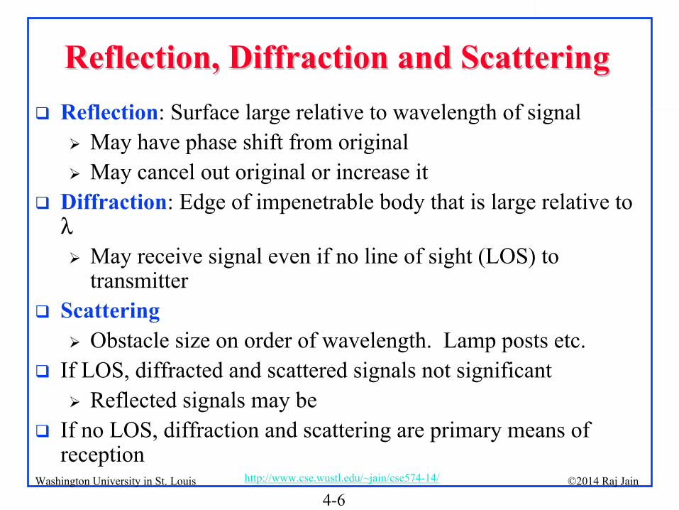
Reflection: Surface large relative to wavelength of signal
May have phase shift from original
May cancel out original or increase it
Diffraction: Edge of impenetrable body that is large relative to λ
May receive signal even if no line of sight (LOS) to transmitter
Scattering
Obstacle size on order of wavelength. Lamp posts etc.
If LOS, diffracted and scattered signals not significant
Reflected signals may be
If no LOS, diffraction and scattering are primary means of reception

4-7©2014 Raj Jainhttp://www.cse.wustl.edu/~jain/cse574-14/Washington University in St. Louis
Channel ModelChannel Model
Power profile of the received signal can be obtained by convolving
the power profile of the transmitted signal with the
impulse response of the channel.
Convolution in time = multiplication in frequency
Signal x, after propagation through the channel H
becomes y: y(f)=H(f)x(f)+n(f)
Here H(f) is channel response, and n(f) is the noise. Note that x, y, H, and n
are all functions of the signal frequency f.
Channel
Base Station Subscriber Station

4-8©2014 Raj Jainhttp://www.cse.wustl.edu/~jain/cse574-14/Washington University in St. Louis
Path LossPath Loss
Power is distributed equally to spherical area 4π
d2
The received power depends upon the wavelength
If the Receiver collects power from area AR
:
Receiving Antenna Gain
This is known as Frii's
Law. Attenuation in free space increases with frequency.

4-9©2014 Raj Jainhttp://www.cse.wustl.edu/~jain/cse574-14/Washington University in St. Louis
MultipathMultipath
Multiple reflected copies of the signal are received
t t

4-11©2014 Raj Jainhttp://www.cse.wustl.edu/~jain/cse574-14/Washington University in St. Louis
Multipath PropagationMultipath Propagation
Inter-symbol Interference
Delay Spread = Time between first and last versions of signal
Fading: Fluctuation in amplitude, phase or delay spread
Multipath may add constructively or destructively Fast fading

4-12©2014 Raj Jainhttp://www.cse.wustl.edu/~jain/cse574-14/Washington University in St. Louis
dd--44
Power LawPower Law
Using a two-ray model
Here, hT
and hR
are heights of transmit and receive antennas
It is valid for distances larger than
Note that the received power becomes independent of the frequency.
Measured results show n=1.5 to 5.5. Typically 4.

4-13©2014 Raj Jainhttp://www.cse.wustl.edu/~jain/cse574-14/Washington University in St. Louis
Small Scale FadingSmall Scale Fading
The signal amplitude can change by moving a few inches Small scale fading
+ = + =

4-14©2014 Raj Jainhttp://www.cse.wustl.edu/~jain/cse574-14/Washington University in St. Louis
ShadowingShadowing
Shadowing gives rise to large scale fading
Position
Received Power

4-15©2014 Raj Jainhttp://www.cse.wustl.edu/~jain/cse574-14/Washington University in St. Louis
Path LossPath Loss
4-16©2014 Raj Jainhttp://www.cse.wustl.edu/~jain/cse574-14/Washington University in St. Louis
Fresnel ZonesFresnel Zones
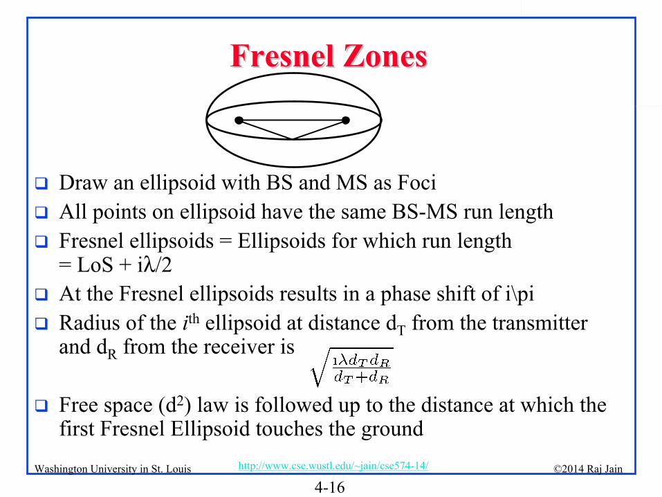
Draw an ellipsoid with BS and MS as Foci
All points on ellipsoid have the same BS-MS run length
Fresnel ellipsoids = Ellipsoids for which run length = LoS
+ iλ/2
At the Fresnel ellipsoids results in a phase shift of i\pi
Radius of the ith
ellipsoid at distance dT
from the transmitter and dR
from the receiver is
Free space (d2) law is followed up to the distance at which the first Fresnel Ellipsoid touches the ground

4-17©2014 Raj Jainhttp://www.cse.wustl.edu/~jain/cse574-14/Washington University in St. Louis
MultiMulti--Antenna SystemsAntenna Systems
Receiver Diversity
Transmitter Diversity
Beam forming
MIMO

4-18©2014 Raj Jainhttp://www.cse.wustl.edu/~jain/cse574-14/Washington University in St. Louis
Receiver DiversityReceiver Diversity
User multiple receive antenna
Selection combining: Select antenna with highest SNR
Threshold combining: Select the first antenna with SNR above a threshold
Maximal Ratio Combining: Phase is adjusted so that all signals have the same phase. Then weighted sum is used to maximize SNR
× × × ×a1 a2 a3 aM
Σ

4-19©2014 Raj Jainhttp://www.cse.wustl.edu/~jain/cse574-14/Washington University in St. Louis
Transmitter DiversityTransmitter Diversity
Use multiple antennas to transmit the signal Ample space, power, and processing capacity at the transmitter
(but not at the receiver).
If the channel is known, phase each component and weight it before transmission so that they arrive in phase at the receiver
and maximize SNR
If the channel is not known, use space time block codes
× × × ×a1 a2 a3 aM
4-20©2014 Raj Jainhttp://www.cse.wustl.edu/~jain/cse574-14/Washington University in St. Louis
Beam formingBeam forming
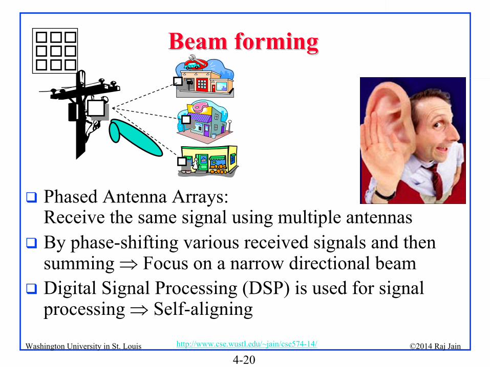
Phased Antenna Arrays: Receive the same signal using multiple antennas
By phase-shifting various received signals and then summing Focus on a narrow directional beam
Digital Signal Processing (DSP) is used for signal processing Self-aligning

4-21©2014 Raj Jainhttp://www.cse.wustl.edu/~jain/cse574-14/Washington University in St. Louis
MIMOMIMO
Multiple Input Multiple Output
RF chain for each antenna Simultaneous reception or transmission of multiple streams
2x3

4-22©2014 Raj Jainhttp://www.cse.wustl.edu/~jain/cse574-14/Washington University in St. Louis
Multiple Access MethodsMultiple Access Methods
Source: Nortel

4-23©2014 Raj Jainhttp://www.cse.wustl.edu/~jain/cse574-14/Washington University in St. Louis
OFDMOFDM
Orthogonal Frequency Division Multiplexing
Ten 100 kHz channels are better than one 1 MHz Channel Multi-carrier modulation
Frequency band is divided into 256 or more sub-bands. Orthogonal Peak of one at null of others
Each carrier is modulated with a BPSK, QPSK, 16-QAM, 64- QAM etc depending on the noise (Frequency selective fading)
Used in 802.11a/g, 802.16, Digital Video Broadcast handheld (DVB-H)
Easy to implement using FFT/IFFT

4-24©2014 Raj Jainhttp://www.cse.wustl.edu/~jain/cse574-14/Washington University in St. Louis
Advantages of OFDMAdvantages of OFDM
Easy to implement using FFT/IFFT
Computational complexity = O(B log BT) compared to previous O(B2T) for Equalization. Here B is the bandwidth and T is the delay spread.
Graceful degradation if excess delay
Robustness against frequency selective burst errors
Allows adaptive modulation and coding of subcarriers
Robust against narrowband interference (affecting only some subcarriers)
Allows pilot
subcarriers for channel estimation

4-25©2014 Raj Jainhttp://www.cse.wustl.edu/~jain/cse574-14/Washington University in St. Louis
OFDM: Design considerationsOFDM: Design considerations
Large number of carriers Smaller data rate per carrier Larger symbol duration Less inter-symbol interference
Reduced subcarrier spacing Increased inter-carrier interference due to Doppler spread in mobile applications
Easily implemented as Inverse Discrete Fourier Transform (IDFT) of data symbol block
Fast Fourier Transform (FFT) is a computationally efficient way of computing DFT
10 Mbps 1 Mbps
1 μs0.1 μs

4-26©2014 Raj Jainhttp://www.cse.wustl.edu/~jain/cse574-14/Washington University in St. Louis
OFDMAOFDMA
Orthogonal Frequency Division Multiple Access
Each user has a subset of subcarriers for a few slots
OFDM systems use TDMA
OFDMA allows Time+Freq DMA 2D Scheduling
TimeTime
Freq.
OFDMAFrequency
User 1 User 2 User 3
U1 U2U3U4 U5
U6 U7

4-27©2014 Raj Jainhttp://www.cse.wustl.edu/~jain/cse574-14/Washington University in St. Louis
Scalable OFDMA (SOFDMA)Scalable OFDMA (SOFDMA)
OFDM symbol duration = f(subcarrier spacing)
Subcarrier spacing = Frequency bandwidth/Number of subcarriers
Frequency bandwidth=1.25 MHz, 3.5 MHz, 5 MHz, 10 MHz, 20 MHz, etc.
Symbol duration affects higher layer operation Keep symbol duration constant at 102.9 us
Keep subcarrier spacing 10.94 kHz Number of subcarriers ∝
Frequency bandwidth
This is known as scalable OFDMA

4-28©2014 Raj Jainhttp://www.cse.wustl.edu/~jain/cse574-14/Washington University in St. Louis
SummarySummary
1.
Path loss increase at a power of 2 to 5.5 with distance.2.
Fading = Changes in power changes in position3.
Fresnel zones = Ellipsoid with distance of LoS+iλ/2 Any obstruction of the first zone will increase path loss
4.
Multiple Antennas: Receive diversity, transmit diversity, Smart Antenna, MIMO
5.
OFDM splits a band in to many orthogonal subcarriers. OFDMA = FDMA + TDMA

4-29©2014 Raj Jainhttp://www.cse.wustl.edu/~jain/cse574-14/Washington University in St. Louis
Homework 4Homework 4A.
Determine the mean received power at a SS. The channel between a base station at 14 m and the subscriber stations at 4m at a distance of 500m. The Transmitter and Reciver
antenna gains are 10dB and 5 dB respectively. Use a power exponent of 4. Transmitted power is 30 dBm.
B.
With a subcarrier spacing of 10 kHz, how many subcarriers will be used in a system with 8 MHz channel bandwidth and what size FFT will be used?
C.
In a scalable OFDMA system, the number of carriers for 10 MHz channel is 1024. How many carriers will be used if the channel was 1.25 MHz, 5 MHz, or 8.75 MHz.

4-30©2014 Raj Jainhttp://www.cse.wustl.edu/~jain/cse574-14/Washington University in St. Louis
Wikipedia LinksWikipedia Links
http://en.wikipedia.org/wiki/Omnidirectional_antenna
http://en.wikipedia.org/wiki/Antenna_gain
http://en.wikipedia.org/wiki/Equivalent_isotropically_radiated_power
http://en.wikipedia.org/wiki/High-gain_antenna
http://en.wikipedia.org/wiki/Signal_reflection
http://en.wikipedia.org/wiki/Scattering
http://en.wikipedia.org/wiki/Path_loss
http://en.wikipedia.org/wiki/Free-space_path_loss
http://en.wikipedia.org/wiki/Log-distance_path_loss_model
http://en.wikipedia.org/wiki/Multipath_propagation
http://en.wikipedia.org/wiki/Multipath_interference
http://en.wikipedia.org/wiki/Intersymbol_interference
http://en.wikipedia.org/wiki/Fading
http://en.wikipedia.org/wiki/Shadow_fading
http://en.wikipedia.org/wiki/Fresnel_zone

4-31©2014 Raj Jainhttp://www.cse.wustl.edu/~jain/cse574-14/Washington University in St. Louis
Wikipedia Links (Cont)Wikipedia Links (Cont)
http://en.wikipedia.org/wiki/Antenna_diversity
http://en.wikipedia.org/wiki/Beamforming
http://en.wikipedia.org/wiki/Antenna_array_(electromagnetic)
http://en.wikipedia.org/wiki/Phased_array
http://en.wikipedia.org/wiki/Smart_antenna
http://en.wikipedia.org/wiki/Multiple-input_multiple-
output_communications
http://en.wikipedia.org/wiki/Diversity_combining
http://en.wikipedia.org/wiki/Maximal-ratio_combining
http://en.wikipedia.org/wiki/Orthogonal_frequency-division_multiplexing
http://en.wikipedia.org/wiki/Orthogonal_frequency-
division_multiple_access

4-32©2014 Raj Jainhttp://www.cse.wustl.edu/~jain/cse574-14/Washington University in St. Louis
AcronymsAcronyms
BPSK
Binary Phase-Shift Keying
BS
Base Station
dB
DeciBels
dBi
DeciBels
Intrinsic
dBm
DeciBels
milliwatt
DFT
Discrete Fourier Transform
DMA
Direct Memory Access
DSP
Digital Signal Processing
DVB-H
Digital Video Broadcast handheld
FDMA
Frequency Division Multiple Access
FFT
Fast Fourier Transform
IDFT
Inverse Discrete Fourier Transform
IFFT
Inverse Fast Fourier Transform
ISI
Inter-symbol interference
kHz
Kilo Hertz
LoS
Line of Sight

4-33©2014 Raj Jainhttp://www.cse.wustl.edu/~jain/cse574-14/Washington University in St. Louis
Acronyms (Cont) Acronyms (Cont)
MHz
Mega Hertz
MIMO
Multiple Input Multiple Output
MS
Mobile Station
OFDM
Orthogonal Frequency Division Multiplexing
OFDMA
Orthogonal Frequency Division Multiple Access
QAM
Quadrature Amplitude Modulation
QPSK
Quadrature Phase-Shift Keying
RF
Radio Frequency
SNR
Signal to Noise Ratio
SS
Subscriber Station
STBC
Space Time Block Codes
TDMA
Time Division Multiple Access