introduction to verisurf x - 3dgage · pdf fileintroduction to verisurf x ... which is based...
TRANSCRIPT
Introduction to Verisurf X
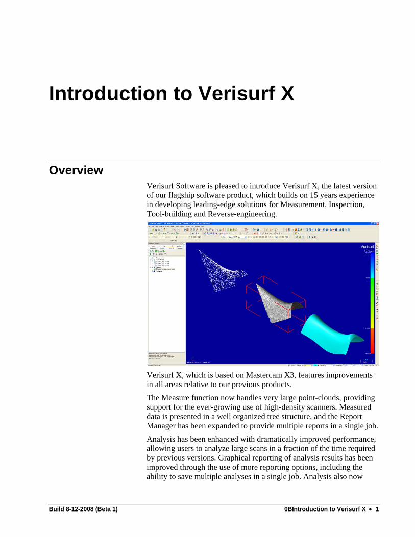
Overview Verisurf Software is pleased to introduce Verisurf X, the latest version of our flagship software product, which builds on 15 years experience in developing leading-edge solutions for Measurement, Inspection, Tool-building and Reverse-engineering.
Verisurf X, which is based on Mastercam X3, features improvements in all areas relative to our previous products. The Measure function now handles very large point-clouds, providing support for the ever-growing use of high-density scanners. Measured data is presented in a well organized tree structure, and the Report Manager has been expanded to provide multiple reports in a single job. Analysis has been enhanced with dramatically improved performance, allowing users to analyze large scans in a fraction of the time required by previous versions. Graphical reporting of analysis results has been improved through the use of more reporting options, including the ability to save multiple analyses in a single job. Analysis also now
Build 8-12-2008 (Beta 1) 0BIntroduction to Verisurf X • 1
includes real-time surface scans, which provide instant feedback for tolerance assessment. The suite of Reverse-engineering tools has been greatly expanded to provide support for surface meshes, including very large STL files. Meshing, cropping, editing and slicing tools make it possible to create complex surfaces from point-clouds quickly and with little user input. Meshes can be used in lieu of surfaces for analysis and tool-building. Model-based Definition (MBD) has been enhanced to provide more tools and greater support for complex callouts. In addition, the MBD is always ‘live’, and can be viewed on-screen during all Verisurf operations such as measurement, analysis, tool-building and reverse-engineering. The following sections describe the functionality of Verisurf X in the new Mastercam X3 environment. For those of you familiar with the Verisurf 9.1 family of products, parallels are drawn between the old and new interfaces, to help in the transition.
Build 8-12-2008 (Beta 1) 0BIntroduction to Verisurf X • 2

Welcome to Verisurf X Thank you for your support and usage of Verisurf Software and welcome to our latest release. As you may well know Verisurf is now Verisurf X and based on the Mastercam X2 interface. This is a completely different interface from the Mastercam V9 interface however many of the tools you have used in V9 are still available, though greatly enhanced, in X. You will find the standard modules associated with Verisurf such as Align, Build, Analysis, Report Manager, Automate, MBD and Reverse. Each of these modules has been re-coded from scratch to provide a better quality product for the end-user.
Build 8-12-2008 (Beta 1) 0BIntroduction to Verisurf X • 3
Getting Help
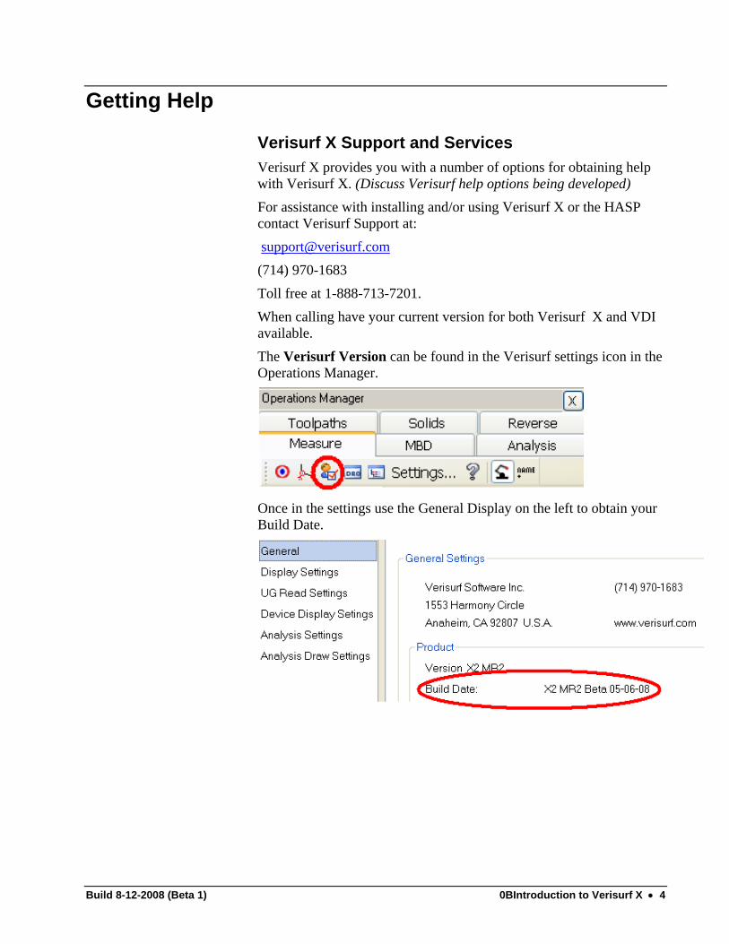
Verisurf X Support and Services Verisurf X provides you with a number of options for obtaining help with Verisurf X. (Discuss Verisurf help options being developed) For assistance with installing and/or using Verisurf X or the HASP contact Verisurf Support at: [email protected] (714) 970-1683 Toll free at 1-888-713-7201. When calling have your current version for both Verisurf X and VDI available. The Verisurf Version can be found in the Verisurf settings icon in the Operations Manager.
Once in the settings use the General Display on the left to obtain your Build Date.
Build 8-12-2008 (Beta 1) 0BIntroduction to Verisurf X • 4

The VDI Version can be found by clicking the menu button in the VDI and selecting the About option. The VDI version will then be displayed.
Build 8-12-2008 (Beta 1) 0BIntroduction to Verisurf X • 5

Mastercam X Support and Services Mastercam X has a comprehensive on-line help for aiding you with the design product. (Use the help pull-down for Mastercam topic help)
Use the following Web sites to find information on Mastercam:
• www.emastercam.com Mastercam global user forum
• www.mastercam.com CNC Software Inc corporate site
• www.mastercamedu.com Mastercam education site
Build 8-12-2008 (Beta 1) 0BIntroduction to Verisurf X • 6

Starting Verisurf X This document assumes that you have successfully installed Verisurf X, have completed the necessary post-installation procedures for your VDI and drivers, and are ready to begin using Verisurf X.
To start Verisurf X 1. Double-click the Verisurf X icon on your desktop:
(PICTURE OF VERISURF X ICON GOES HERE) Or select Verisurf X from the Windows Program menu.
About HASP Verisurf X uses single- user licensing which requires a special piece of hardware called a HASP (sometimes called a dongle or a SIM) attached to the USB port of your computer. If you receive the following message when starting Verisurf X, the HASP is either missing or not properly configured:
Build 8-12-2008 (Beta 1) 0BIntroduction to Verisurf X • 7

Graphic User Interface
• Menu – Allows you to select all the functions from drop down
menus
• Toolbars – Can be used instead of menu to select functions
• Ribbon bar – Allows you to enter values and settings for entities you are creating or modifying.
• Interactive prompt – Prompts the user for info or an action
• Status bar – Allows you to set the attributes (color, level, style and width) and the View/Plane and Z depth currently used
• Graphics window – Workspace area where the geometry displays
• MRU toolbar – List of the most recently used functions
Build 8-12-2008 (Beta 1) 0BIntroduction to Verisurf X • 8
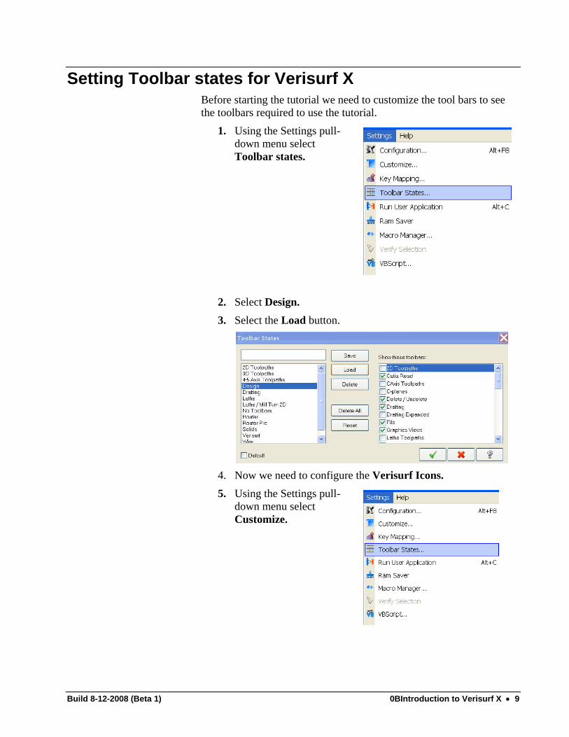
Setting Toolbar states for Verisurf X Before starting the tutorial we need to customize the tool bars to see the toolbars required to use the tutorial.
1. Using the Settings pull-down menu select Toolbar states.
2. Select Design. 3. Select the Load button.
4. Now we need to configure the Verisurf Icons. 5. Using the Settings pull-
down menu select Customize.
Build 8-12-2008 (Beta 1) 0BIntroduction to Verisurf X • 9
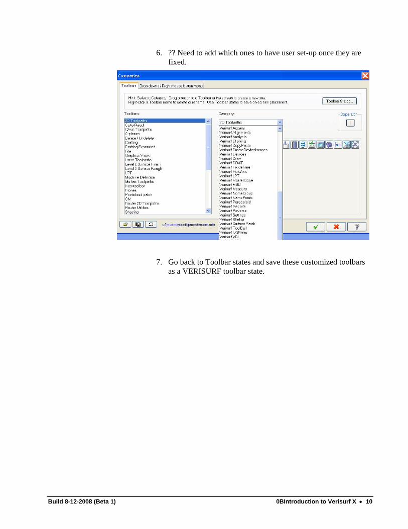
6. ?? Need to add which ones to have user set-up once they are fixed.
7. Go back to Toolbar states and save these customized toolbars
as a VERISURF toolbar state.
Build 8-12-2008 (Beta 1) 0BIntroduction to Verisurf X • 10

Verisurf X Interface This exercise will utilize the items discussed in the Introduction to Verisurf X lecture. You will practice the following skills that were discussed:
• Opening up a part file • Zoom, Fit, Pan, Rotation • Color – SUBJECT TO CHANGE • Level – SUBJECT TO CHANGE • Z level – SUBJECT TO CHANGE • Attributes – SUBJECT TO CHANGE
Before beginning, you should create a working folder to store all your parts as you work on them. C:\mcamx\data\training is suggested.
Opening a file 1. Choose the commands File > Open. 2. Go to the c:mcamx/training folder and choose the part file named
Verisurf tutor part.mcx.
Note: You may notice that the files of type is set to *.MCX. This is where you can change what type of file to bring in based on which converters you have.
Build 8-12-2008 (Beta 1) 0BIntroduction to Verisurf X • 11

Changing the graphics window display Mastercam provides several tools and methods for changing the appearance of the geometry and toolpaths in the graphics window. A few of the most commonly used methods are listed below.
Fit geometry to screen: Maximizes your view of visible geometry in the graphics window. For more information, see Fit.
Pan: Moves geometry within the graphics window. For more information, see Pan.
Set screen center: Repositions the center of the graphics window, based on the new center point you specify.
Repaint screen: Refreshes the graphics window. For more information, see Repaint.
Regenerate screen: Rebuilds the display list at the current screen scale. For more information, see Regenerate.
Zoom functions: Increases or decreases the scale of images in the graphics window. For more information, see Zoom functions.
View Selection –Choose from Top, Front, Side, Iso or the pull-down for views you may have set. Tip: You can use the mouse wheel any time—without selecting a function—to zoom and unzoom the contents of the graphics window.
Exercise: Model Manipulation 1. After the instructor lecture try all these tools until you feel
comfortable with their usage by being able to maneuver around the part..
Build 8-12-2008 (Beta 1) 0BIntroduction to Verisurf X • 12
Build 8-12-2008 (Beta 1) 0BIntroduction to Verisurf X • 13
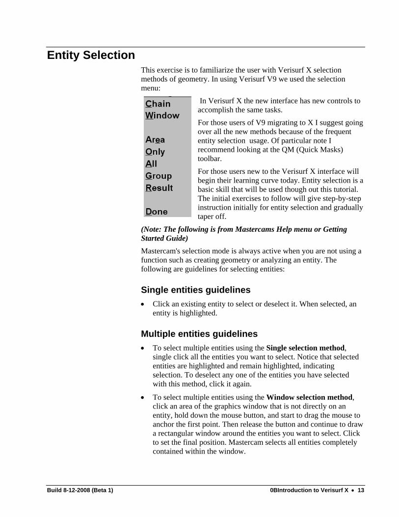
Entity Selection This exercise is to familiarize the user with Verisurf X selection methods of geometry. In using Verisurf V9 we used the selection menu:
In Verisurf X the new interface has new controls to accomplish the same tasks. For those users of V9 migrating to X I suggest going over all the new methods because of the frequent entity selection usage. Of particular note I recommend looking at the QM (Quick Masks) toolbar. For those users new to the Verisurf X interface will begin their learning curve today. Entity selection is abasic skill that will be used though out this tutThe initial exercises to follow will give step-by-sinstruction initially for entity selection and graduallytaper off.
orial.
tep
(Note: The following is from Mastercams Help menu or Getting Started Guide) Mastercam's selection mode is always active when you are not using a function such as creating geometry or analyzing an entity. The following are guidelines for selecting entities:
Single entities guidelines • Click an existing entity to select or deselect it. When selected, an
entity is highlighted.
Multiple entities guidelines • To select multiple entities using the Single selection method,
single click all the entities you want to select. Notice that selected entities are highlighted and remain highlighted, indicating selection. To deselect any one of the entities you have selected with this method, click it again.
• To select multiple entities using the Window selection method, click an area of the graphics window that is not directly on an entity, hold down the mouse button, and start to drag the mouse to anchor the first point. Then release the button and continue to draw a rectangular window around the entities you want to select. Click to set the final position. Mastercam selects all entities completely contained within the window.

• To select multiple entities using the Polygon selection method, choose Polygon from the Selection Methods drop-down list and click anywhere in the graphics window. This location will be the start point of the polygon. Continue by clicking points to create your desired shape. Close the polygon by double-clicking the last point or pressing the Enter key.
• To select entities using the Chain selection method, hold down the Shift key and select a single entity that is part of a chain of other entities. Alternatively, you can choose Chain from the Selection Methods drop-down list and click an entity that is connected to other entities. For example, holding down the Shift key and clicking one side of a rectangle selects all four sides and clicking one line that is connected to another selects both lines.
• To select entities using the Partial Chain selection method, hold down the Shift key and select a single entity that is part of a chain of other entities. This first selection also specifies the chaining direction, so be careful where you click. Keeping the Shift key down, select the last entity in the chain.
• To unselect currently selected entities, while at the same time selecting all unselected entities, click the Invert Selection button in the General Selection ribbon bar.
Note: Left-click a selection method to choose it for a single selection event. Right-click a method to lock it for multiple selections. Note: To finalize multiple-entity selections, press Enter, or click the End Selection button in the ribbon bar. Note, however, that you can end a series of selections by double-clicking the last entity of the selection. For example, to select three lines using the single selection method, click the first two lines. Then double-click the third line to end the selection process. (The double-click method does not work with polygon and vector selections, which instead use the double-click to complete the polygon or vector.)
All entities guidelines • Choose the All button to open the Select All dialog box and click
the All Entities bar at the top of the dialog. The dialog box closes, and Mastercam selects all entities.
• Use Quick Masks to control the masking-selection mode with a single mouse click.
Unselecting entities guidelines • To unselect all entities, choose the UnSelect All button. To
unselect one or more entities (but not all), re-select each entity you
Build 8-12-2008 (Beta 1) 0BIntroduction to Verisurf X • 14

want to unselect. If Mastercam is at the root level (that is, not inside a function), you can also press Esc to unselect all entities. 1. Using the Verisurf Tutor part
to practice the different selection methods. Choose the Level states Manager in the Attributes toolbar at the bottom of the screen.
2. Configure your Level States Manager to give visibility to only the VERISURF LOGO.
3. Practice the entity selection method of SINGLE and
WINDOW on the lettering. Select the entities and then delete them. Hit UNDO after DELETE to return to original.
4. Practice the entity selection method of CHAIN and PARTIAL CHAIN on the box surrounding the letters. Select the entities and then delete them. Hit UNDO after DELETE to return to original.
Build 8-12-2008 (Beta 1) 0BIntroduction to Verisurf X • 15

Quick Masks Mastercam's Quick Masks are time-saving functions that allow you to select entities by type with a single mouse click, without having to open the All or Only dialog boxes. Figure 3-10: Quick Masks Toolbars
By default, the Quick Masks toolbar is docked vertically, directly below the MRU toolbar along the rightmost edge of the Mastercam window. Quick Masks (QM) functions support different right–click and left–click actions.
• Left–clicking sets masking to select all entities of the specified type.
• Right–clicking sets masking for a single selection. For example, suppose you have a rectangle that comprises four lines. If you left–click the QM Lines function, Mastercam selects all four of the rectangle's lines. If you right–click the function, you can select lines (and only lines) one by one. QM functions include Points, Lines, Arcs, Splines, Surfaces, Solids, Drafting, Wireframe, Surface Curves, Color, Level, Xform Group, and Xform Results. Use the General Selection category in Settings, Customize to add QM functions to toolbars. You can also set up keyboard shortcuts for QM functions by choosing the General Selection category in Settings, Key Mapping.
Build 8-12-2008 (Beta 1) 0BIntroduction to Verisurf X • 16

Entity Selection (Advanced) When creating geometry, you can use several selection methods to select positions and other entities in the graphics window, including:
• Clicking with the left mouse button to choose one or more entities, usually at the prompting of a function.
• Choosing General Selection ribbon bar options. • Chaining (page 23).
Using the General Selection Ribbon Bar The General Selection ribbon bar operates in two different modes Standard Selection and Solid Selection. The availability of either mode is based on the types of entities that are in the current file and the functions you choose from Mastercam menus and toolbars. If you choose a Mastercam function specific to a solid entity, the General Selection ribbon bar automatically switches to the Solid Selection mode. Figure 3-7: General Selection Solid Selection mode
If there are no solids in your file, the Solid Selection mode is not available; you can use only Standard Selection options. Figure 3-8: General Selection Standard Selection mode
If the General Selection ribbon bar is available for use when no other function is active, you can select entities prior to choosing a function by using the cursor or combinations of the cursor and keystrokes, such as [Shift+Click]. Then choose a function to apply to the selected entities. Some functions work in conjunction with the General Selection ribbon bar. In these functions, the General Selection ribbon bar becomes active when you are prompted to select entities for the function.
Build 8-12-2008 (Beta 1) 0BIntroduction to Verisurf X • 17

General Selection Methods Use the General Selection method drop-down list to set the method by which you select entities in the graphics window. Selecting a method option limits selection to that method. You can left–click a method to choose it for a single selection event, or right–click a method to lock it for multiple selections. Once you have chosen one of the following selection methods, you can return to the standard selection method
by clicking the Standard Selection button. To finalize multiple-entity selections, you can press [Enter], or
click the End Selection button in the ribbon bar. Note, however, that you can end a series of selections by double clicking the last entity of the selection. For example, to select three lines using the single selection method, click the first two lines. Then double-click the third line to end the selection process. (The double-click method does not work with polygon and vector selections, which instead use the double-click to complete the polygon or vector.) From the General Selection ribbon bar, choose one of the following Selection methods to lock the method in place and disable the others. Chain: Select/chain entities that are connected to other entities. For example, clicking one side of a rectangle selects all four sides, and clicking one line that is connected to another selects both lines. *Window: Select entities by drawing a window around them. *Polygon: Select entities by drawing a polygon around the entities. Double–click to complete the polygon. Single: Select individual entities by clicking them with the mouse. Area: Select multiple nested shapes with a single mouse click. Vector: Select multiple entities by drawing a vector line through them. All entities the vector intersects are selected. *The Window and Polygon selection methods are controlled by the choices you make in the Entity selection settings drop-down list.
Build 8-12-2008 (Beta 1) 0BIntroduction to Verisurf X • 18

________________________________________________ Note: All selection methods, including the Solids selection
methods, can be added to toolbars and your graphics window right–click menu using Settings, Customize.
_______________________________________________
Window and Single selection are Mastercam’s standard selection methods; both are active at the same time. When these options are in effect, you can use the mouse and either a single [Click] or [Shift+Click] to select one or more entities. Or, you can drag a window and select all entities that are completely inside the window.
_____________________________________________ TIP: You can switch from any selection method to Window by
holding down the [Ctrl] key and selecting the first window position in the graphics window.
__________________________________________________ When you choose a selection method from the drop-down list, it remains set until you perform one of the following actions:
• Click the Standard Selection button in the General Selection ribbon bar to reset it to the Window method.
• Choose another method from the list. • Hold down the [Shift] or [Alt] keys to override the default (seeTips
below for override details.) __________________________________________________ TIPS: • In Standard selection mode, you can switch from the Window method to Vector selection by holding down the [Alt] key. • To override any selection method and toggle between the Chain and Area selection methods, hold down the [Shift] key when selecting an entity or a position. If you place the cursor on an entity while holding down the [Shift] key, the Chain method is active; otherwise, the Area method is active. ___________________________________________________
Build 8-12-2008 (Beta 1) 0BIntroduction to Verisurf X • 19

Entity Selection Settings The Entity selection field in the General Selection ribbon bar determines how the Polygon and Window selection methods choose to include entities. Before selecting entities with these methods, use this field to choose one of the following: In / Out Select only entities that lie completely inside or
outside the window.
In + / Out+ Select entities that lie completely inside or outside and entities that intersect the window.
Intersect Select only entities that intersect the window. ________________________________________________ TIP: To instantly reverse entity selection (deselect selected entities and select unselected entities), click the Invert Selection button. ________________________________________________
Build 8-12-2008 (Beta 1) 0BIntroduction to Verisurf X • 20

Masking A selection mask is a defined set of criteria you use to quickly select entities in the graphics window. Using a selection mask with a complex part file ensures that you select only and all of the specific entities you want. When working with selection masks, you can:
• Define a selection mask to use once and discard (default).
• Make the selection mask active until you turn it off or exit the Mastercam session.
• Save the selection mask criteria to a file (.MASK) that you can later open and reuse.
• Open an existing selection mask file and apply it. • Use left– and right–click Quick Masks to select all or only
specific entity type. To use a mask for selection, click the All or Only buttons in the General Selection ribbon bar.
• Choosing All opens the Select All dialog box. Use this dialog box to define and apply a mask that automatically selects all entities in the current file that match the mask criteria. You can choose to apply the criteria and select all entities, or only entities in a specified group, including groups created by Xform functions.
• Choosing Only opens the Select Only dialog box. Use this dialog box to set restrictions on the entities that are available for selection in the graphics window. When you apply the Only mask, you use other General Selection methods to select only those entities that match the mask criteria you define. Until you clear the mask, you are restricted from selecting entities that are excluded by the mask.
Build 8-12-2008 (Beta 1) 0BIntroduction to Verisurf X • 21
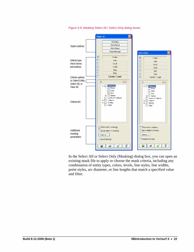
Figure 3-9: Masking Select All / Select Only dialog boxes
In the Select All or Select Only (Masking) dialog box, you can open an existing mask file to apply or choose the mask criteria, including any combination of entity types, colors, levels, line styles, line widths, point styles, arc diameter, or line lengths that match a specified value and filter.
Build 8-12-2008 (Beta 1) 0BIntroduction to Verisurf X • 22
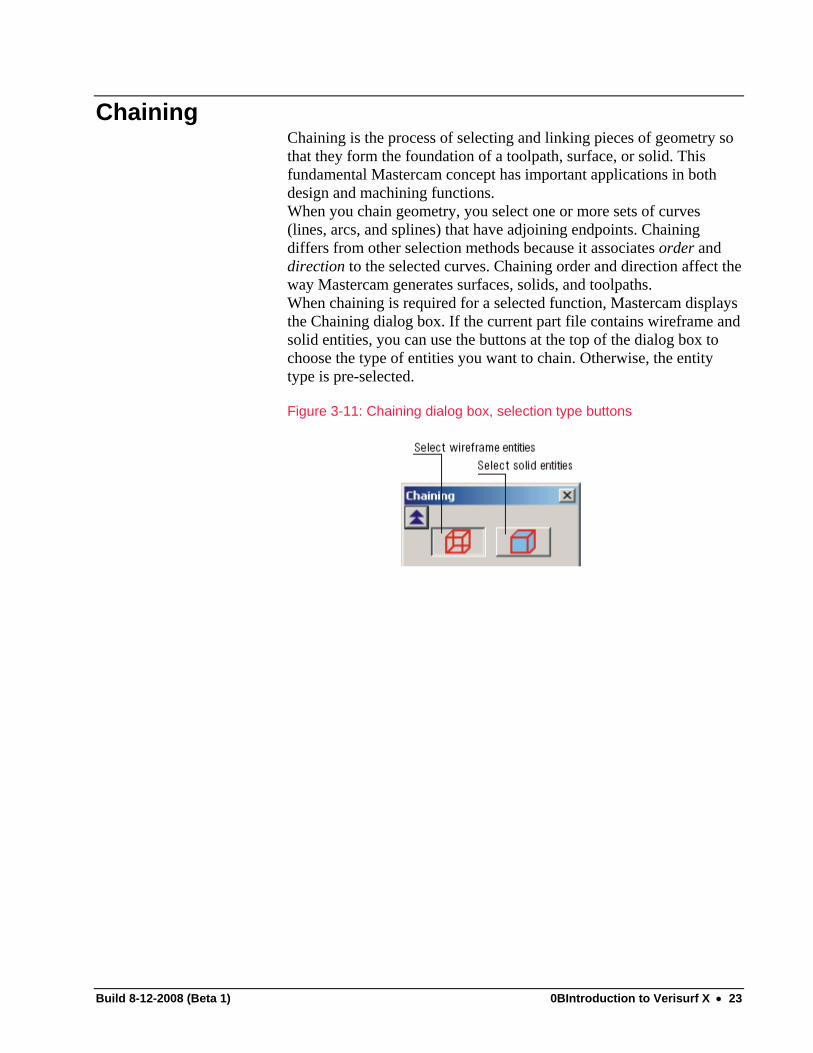
Chaining Chaining is the process of selecting and linking pieces of geometry so that they form the foundation of a toolpath, surface, or solid. This fundamental Mastercam concept has important applications in both design and machining functions. When you chain geometry, you select one or more sets of curves (lines, arcs, and splines) that have adjoining endpoints. Chaining differs from other selection methods because it associates order and direction to the selected curves. Chaining order and direction affect the way Mastercam generates surfaces, solids, and toolpaths. When chaining is required for a selected function, Mastercam displays the Chaining dialog box. If the current part file contains wireframe and solid entities, you can use the buttons at the top of the dialog box to choose the type of entities you want to chain. Otherwise, the entity type is pre-selected. Figure 3-11: Chaining dialog box, selection type buttons
Build 8-12-2008 (Beta 1) 0BIntroduction to Verisurf X • 23

Figure 3-12: Chaining dialog boxes
Chaining Wireframe Geometry Chaining wireframe entities is similar to using the standard mode in General Selection. The entities you select when chaining appear in the selection color. Use options in the Chaining dialog box to choose:
• Geometry plane: You can chain entities only in 3D or the current construction plane (Cplane). Chaining in 3D allows the chain to span planes. Cplane chaining is two-dimensional; all entities must lie in a single plane.
• Selection method: Like General selection, chain selection methods include chained entities, single entity, window, polygon, and vector selection. You can also chain a series of non-adjacent points (useful in spline and surface creation) and create partial or open chains consisting of all adjacent entities between a start point and an end point. The Window and Polygon methods allow you to control whether entities are selected inside or outside of the selection area.
Use the following functions in the Chaining dialog box to change or correct chains as you create them.
Build 8-12-2008 (Beta 1) 0BIntroduction to Verisurf X • 24
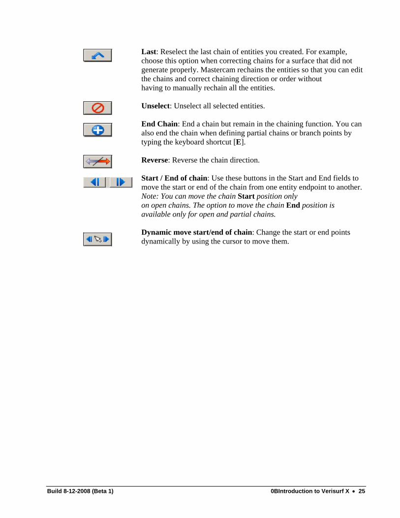
Last: Reselect the last chain of entities you created. For example, choose this option when correcting chains for a surface that did not generate properly. Mastercam rechains the entities so that you can edit the chains and correct chaining direction or order without having to manually rechain all the entities. Unselect: Unselect all selected entities. End Chain: End a chain but remain in the chaining function. You can also end the chain when defining partial chains or branch points by typing the keyboard shortcut [E]. Reverse: Reverse the chain direction. Start / End of chain: Use these buttons in the Start and End fields to move the start or end of the chain from one entity endpoint to another. Note: You can move the chain Start position only on open chains. The option to move the chain End position is available only for open and partial chains. Dynamic move start/end of chain: Change the start or end points dynamically by using the cursor to move them.
Build 8-12-2008 (Beta 1) 0BIntroduction to Verisurf X • 25

Setting Attributes All Mastercam entities have basic attributes (physical characteristics). Based on the entity type, attributes can include:
• Color • Point style • Line style and width • Level
Changing physical attributes when you are working with complex parts is a very powerful technique you will use often to organize your work. Use the Status bar fields to quickly and easily select new entity attributes. Figure 3-13: Status bar
In this section, you will learn about:
• Setting Attributes for New Entities (page 27) • Changing Entity Attributes (page 30)
Build 8-12-2008 (Beta 1) 0BIntroduction to Verisurf X • 26

Setting Attributes for New Entities The attributes you set using the following methods are automatically applied in the current Mastercam session to the new entities you create. You can set new entity attributes in several ways.
To use an existing entity to set color, line, point, and level attributes:
Press [Alt+X] on the keyboard and select an entity in the graphics window. The Status bar color, point style, line style, and line width fields are changed to the selected entity’s attributes.
To set a specific attribute: 1. Choose one or more attribute fields and specify the value.
Color: Choose Select from the System color drop-down list and select an entity in the graphics window. Or, click the current color field to select a color from the Colors dialog box. Point Style, Line Style, and Line Width: Select new values from the drop-down lists. Level: To set the main level:
• Type the level number in the field. • Click the arrow and choose a level from the most recently used list. • Click Level to open the Level Manager dialog box, and select an
existing level, or create a new level.
1. Attributes: Click to open the Attributes
dialog box where you can specify color, level, point and line styles, and line width. Click OK to accept the new attributes and close the dialog box.
Build 8-12-2008 (Beta 1) 0BIntroduction to Verisurf X • 27

Figure 3-14: Attributes dialog box
To set attributes for specific entity types (such as points, lines, arcs, solids, surface, and drafting dimensions):
1. Click the Attributes button in the Status bar. 2. In the Attributes dialog box, select the EA Mgr (Entity
Attributes Manager) check box, and then click the EA Mgr button.
3. In the Entity Attributes Manager dialog box, select the entity types, and set the attributes you want to use in the current Mastercam session. Note: The EA Manager is rarely used in conjunction with Verisurf.
Build 8-12-2008 (Beta 1) 0BIntroduction to Verisurf X • 28

Figure 3-15: Entity Attributes Manager dialog box
To open the Color palette dialog box and choose a color, double–click the color sample. Note: You can also use the EA Mgr to apply attributes to files you convert from other programs. Select the option to Include entities created during File-Open. When all entity attributes are set, click OK to accept them and return to the Attributes dialog box.
Build 8-12-2008 (Beta 1) 0BIntroduction to Verisurf X • 29

Changing Existing Entity Attributes Use the following methods to change the attributes of existing entities. Note: These methods do not change the values that appear in the Status bar attributes fields; they apply only to the entities you select in the graphics window.
To change attributes using the right–mouse button:
1. (optional) Use general selection methods to select the entities to change.
2. In the Status bar, position the cursor over the label of the attribute you want to change until the mouse pointer changes to indicate that a right–click option is available. Then right–click.
3. If you selected entities in Step 1, skip to step Step 4. Otherwise, when prompted to select the entities to change, use general selection methods to select the entities. Then press [Enter] or choose End selection in the General selection ribbon bar.
4. Based on the attribute you chose in Step 2, use one of the following dialog boxes to make the necessary changes:
Build 8-12-2008 (Beta 1) 0BIntroduction to Verisurf X • 30
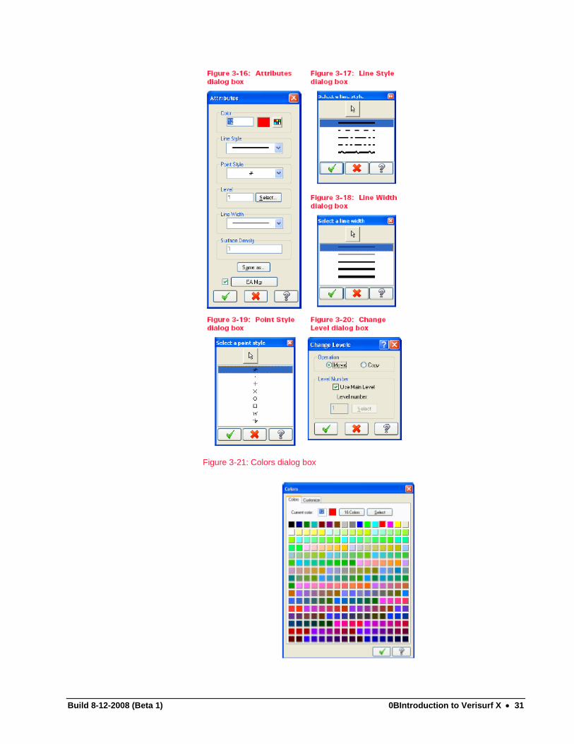
Figure 3-21: Colors dialog box
Build 8-12-2008 (Beta 1) 0BIntroduction to Verisurf X • 31

5. Click OK to apply the change to the selected entities and close the attribute dialog box.
To change the attributes of all of a specific type of entity (such as all points, or splines):
1. In the Status bar, click the Attributes button. 2. In the Attributes dialog box, select the EA Mgr (Entity Attributes
Manager) check box, and then click the EA Mgr button. 3. In the Entity Attributes Manager dialog box, select the entity types and
attributes to use when creating new entities in the current Mastercam session.
4. To update all of the selected types of entities that exist in the current file and close the dialog box, click Apply to existing entities. Note: To continue to use these attributes for new entities, leave the EA Mgr check box selected in the Attributes dialog box. To use different attributes, deselect the check box.
Exercise: Changing Color 1. Using the Verisurf tutor part SELECT the Top surface. 2. Right-click the color in the status bar and select 14-Yellow. 3. Click the check mark for OK. 4. Using your chaining skills select the border around the letters. 5. Change them to Light blue -11. 6. Using the Window method SELECT the lettering. 7. Change them to Pink-13.
Build 8-12-2008 (Beta 1) 0BIntroduction to Verisurf X • 32

Working with Levels A Mastercam file can contain separate levels for wireframe, surfaces, drafting entities, and toolpaths. By organizing your files into levels, you control the areas of the drawing you want to be visible at any time and the entities you can select. This control makes it easier to work with the file, and helps prevent you from affecting areas of the drawing you do not want to change. You can name levels and organize multiple levels into Level Sets, which you can hide or display as a group. In this section, you will learn about:
• Setting the Main Level • Using the Level Manager Right–Click Menu
Setting the Main Level In Mastercam, you can create and name up to 2 billion levels and set any one to be the main level. For each level you create, you assign a unique number and, optionally, a name. The main level is the current working level. Any geometry that you create is always placed on the main level. There can be only one main level at a time, but you can change the main level as often as necessary to work with the part. The current main level appears in the Level field in the Status bar to help you keep track of the level you are working in. To set the main level using the Status bar Level field:
• Type the level number in the field. • Click the drop-down arrow in the Level field and choose a
level from the MRU list. • Click the Levels button to open the Level Manager dialog
box.
Build 8-12-2008 (Beta 1) 0BIntroduction to Verisurf X • 33

In the Level Manager dialog box, the main level is highlighted in yellow. Take any one of the following actions to set the main level:
• Click once on the level number in the Number column. • Choose a level to select it. Then right–click and choose
Make Main. • Type a number in the Main Level, Number text box. • Choose the Select button. The Levels Manager dialog box
minimizes so that you can return to the graphics window and select an entity on the level that you want to use. When you select the entity, the Level Manager dialog box expands and shows the main level set to the level of the selected entity.
Using the Level Manager Right–Click Menu The Level Manager offers an extensive right–click menu you can choose from, including:
• Make Main: Set the selected level as the main level. • Get Named Levels: Load a previously saved .CSV (comma
separated value) file containing a level and level set naming scheme into the current file.
• Save Named Levels: Save all levels and level set names in the current file as a .CSV file for reuse in other Mastercam files.
• Report: Create a text-based report of all level details defined in
Build 8-12-2008 (Beta 1) 0BIntroduction to Verisurf X • 34
the Levels Manager dialog box. You can edit, print, and save this report to a file.
• Contrast Rows: Enhance visibility between rows by shading every other row in the Level Manager list.
• Refresh levels list: Redraws the information displayed in the levels list. The following options are enabled only when you right–click in the Level Set column.
• All Level Set On: View a set of levels based on their Level Set name.
• All Level Set Off: Hide a set of levels based on their Level Set name.
Exercise: Changing Levels 1. Use the model from the Exercise: Change color. 2. Move the Letters to a new level 20 called letters. 3. Move the Border to a new level 30 called Border. 4. Move the Top Surface to a new level called Top.
Build 8-12-2008 (Beta 1) 0BIntroduction to Verisurf X • 35

Setting/Changing Color Mastercam supports a palette of 256 colors, which you can customize. You can reduce the palette to 16 colors by choosing the 16 Colors button in the Colors dialog box, or by deselecting the Show 256 colors check box when setting up system configuration parameters in Settings, Configuration, Colors. Use one of the following methods to access the Colors dialog box:
• From the Mastercam menu, choose Screen, Geometry Attributes and select the colors palette button.
• Click the System Colors field in the Status bar. Figure 3-22: Colors dialog box
To select a color:
• Type its ID number in the Current color field. • Click the color in the color palette. • Choose the Select button and click an entity in the graphics window
with the color you want to use. • Choose the Customize tab and use the fields to create a custom color.
Build 8-12-2008 (Beta 1) 0BIntroduction to Verisurf X • 36
Setting Z Depth Use the Z field in the Status bar to set the Z-depth value for the geometry and toolpaths you create. Set the Z depth using one of the following methods:
• Type a value in the field. • Click the drop-down arrow and choose one from the most recently
used list. • Click the Z label and select a position in the graphics window to use
its Z depth value.
Exercise: Z Depth 1. Select FILE > NEW to clear the geometry and clear***
Working in 2D and 3D Mode When creating geometry, use the 2D / 3D Status bar toggle button to set the drawing mode. The default setting is 3D. Click this button to switch between drawing modes.
• In 2D mode, all geometry is created parallel to the current Cplane and, unless specified, at the current Z-depth setting. You can override the Z-depth setting by typing coordinate values that include a Z-depth value different from the current Z-depth setting.
• In 3D mode, the X, Y, and Z coordinates are all read from AutoCursor when sketching dynamically. The Z-depth setting in the Status bar is not used. When working in a 3D environment, you can create entities whose points lie in different planes, or create entities (such as arcs or 2D splines) in planes other than the predefined planes. In both modes, use AutoCursor or the selected function ribbon bar or dialog box fields to enter coordinate values. Some exceptions to this apply to specific entity types.
Build 8-12-2008 (Beta 1) 0BIntroduction to Verisurf X • 37

Build 8-12-2008 (Beta 1) 0BIntroduction to Verisurf X • 38

Views, planes, and coordinate systems Mastercam uses a 3D Cartesian coordinate system to locate your work in three-dimensional space. This means that geometry and toolpath positions are expressed in terms of three coordinate axes—X, Y, and Z. Each axis is signed, which means that it has a positive and a negative direction.
Because actual machining jobs often require you to work with coordinate locations in sophisticated ways, Mastercam includes several useful tools which let you transform, overlay, slice, and otherwise manipulate the coordinate system so that you can draw and measure your part in ways that make sense to you.
The main tool for applying coordinate systems in Mastercam is the view. A view consists of two main parts:
• A plane, or slice through the coordinate system • An origin, or zero point
Views also have names, so they can be saved with the part and selected at a later time. Every Mastercam part includes by default seven views. These correspond to the six faces of a cube (Top, Front, Back, Right, Left, Bottom) and an Isometric view. In addition, you can create your own views, name them, and save them.
Some of the most important applications of views include:
• The graphics view (Gview). This defines the perspective from which you are looking at the part in the graphics window.
• The construction plane (Cplane). This is the plane in which new geometry is created.
You choose one of these functions, then select a view to apply to it. For example, to look at your part from the right side, choose the Gview function, and then select the Right view. To draw geometry on the back of your part, choose the Cplane function and select the Back view.
Build 8-12-2008 (Beta 1) 0BIntroduction to Verisurf X • 39

Because Mastercam breaks these out into separate functions, you can maintain the plane selections for each function independently. For example, you can be looking at the part in isometric view (Gview = Isometric), while drawing geometry on the front of the part (Cplane = Front). The default plane, Top, corresponds to the standard XY plane for simple 2D geometry.
• Choose Gview on the status bar to orient the graphics view. You can also use the menus at the top of the screen: select Views, Standard or Views, Orient.
• Choose Planes on the status bar to set construction planes.
Work coordinate systems
Mastercam also lets you shift and move the coordinate axes themselves. This lets you create a work coordinate system (WCS), which lets you move the coordinate system to your part geometry instead of moving or transforming the part geometry. Think of the WCS view as defining the "shop floor" relative to your part. For example, an aerospace part might be drawn and dimensioned to the tip of the nose or wing. You can use the WCS to align the coordinate axes and origin with the part before creating the toolpath. Then, when you post the toolpath, the NC code will look like the part is flat so you can machine it simply. Or, you can create different WCS’s for different part fixtures and assign work offsets to each one, so that when you post the toolpaths each will start at the zero point with the proper work offset code included automatically.
Gviews, Cplanes, and Tplanes are all measured relative to the WCS and its origin. However, you change the WCS in exactly the same way that you change those functions: create a view which captures the orientation and origin that you desire, then set the WCS equal to it.
Choose WCS on the status bar to realign or create a new work coordinate system. This menu is also the standard way to access the View Manager, which is a central location for editing, renaming, and managing views.
Build 8-12-2008 (Beta 1) 0BIntroduction to Verisurf X • 40
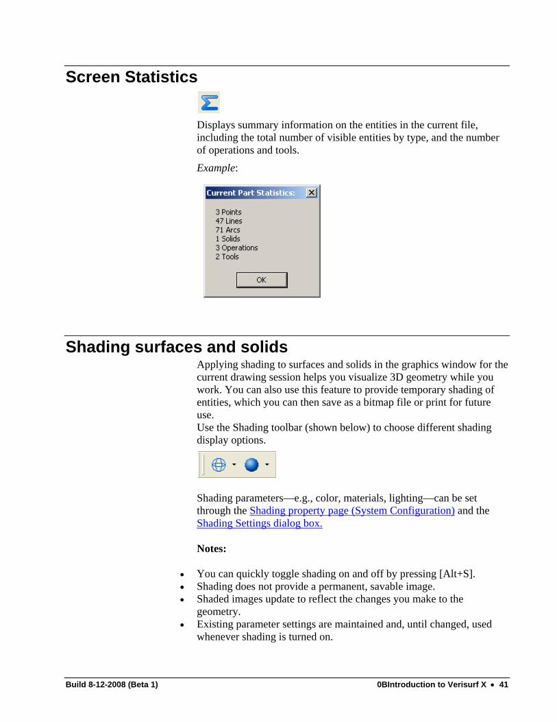
Screen Statistics
Displays summary information on the entities in the current file, including the total number of visible entities by type, and the number of operations and tools. Example:
Shading surfaces and solids Applying shading to surfaces and solids in the graphics window for the current drawing session helps you visualize 3D geometry while you work. You can also use this feature to provide temporary shading of entities, which you can then save as a bitmap file or print for future use. Use the Shading toolbar (shown below) to choose different shading display options.
Shading parameters—e.g., color, materials, lighting—can be set through the Shading property page (System Configuration) and the Shading Settings dialog box.
Notes:
• You can quickly toggle shading on and off by pressing [Alt+S]. • Shading does not provide a permanent, savable image. • Shaded images update to reflect the changes you make to the
geometry. • Existing parameter settings are maintained and, until changed, used
whenever shading is turned on.
Build 8-12-2008 (Beta 1) 0BIntroduction to Verisurf X • 41
• Complex geometry will take some time to shade. In cases such as these, Mastercam will not display the geometry being shaded. Instead, you will see a progress indicator within the status bar that will provide feedback that the shading process is still running. Upon completion of the process, your geometry will appear shaded.
Using the Analyze function
Use the Analyze function to view entity properties and edit some or all of the data, based on the entity type. To analyze entities, use general selection methods and select one or more entities before or after choosing the Analyze function. You can analyze all entity types, including:
• Lines, arcs, points, and splines (parametric and NURBS) • All surfaces and solids • Drafting dimensions
Build 8-12-2008 (Beta 1) 0BIntroduction to Verisurf X • 42

Final Introduction Exercise This exercise will involve opening an IGES file that has all entities on Level 1 and all the same color. You will then use the skills acquired in the preceding sections to move the various entities to named levels and color the entities to specified colors.
1. Open the IGES file VERISURF Intro test.IGS using skills learned from OPENING A FILE on page 11.
2. Use the level manager to verify that it reads as follows:
3. Using the Analyze button to see that then entities are Color
152. Using the skills from ENTITY SELECTION and COLOR CHANGE we will now separate the various entities by COLOR.
4. Select all the surfaces. This can be done with a few different methods. Individually picking them, using the QM(Quick MASK), the Ribbon bar with a masked window, etc. Your method used will develop as you gain proficiency.
5. Once all surfaces are selected use the Color in the STATUS BAR to change them all to BLUE-9
6. Using the same skills change the COLOR of all splines to CYAN-11.
7. Using the same skills change the COLOR of all arcs to GREEN-10.
Build 8-12-2008 (Beta 1) 0BIntroduction to Verisurf X • 43

8. Now change the LEVEL of each group of different colored entities to the following.
• Level 5 for the BLUE surfaces • Level 2 for GREEN arcs • Level 10 for CYAN Splines
9. The last step is to move the Top Surface to level 1 and change
the names of the levels to the following:
10. Have the instructor check your work.
Build 8-12-2008 (Beta 1) 0BIntroduction to Verisurf X • 44