introduction to primary wastewater treatment wastewater treatment.pdf · introduction to primary...
TRANSCRIPT
Introduction to Primary Wastewater Treatment Course No: C02-034
Credit: 2 PDH
J. Paul Guyer, P.E., R.A., Fellow ASCE, Fellow AEI
Continuing Education and Development, Inc. 9 Greyridge Farm Court Stony Point, NY 10980 P: (877) 322-5800 F: (877) 322-4774 [email protected]
An Introduction to Primary Wastewater Treatment
J. Paul Guyer, P.E., R.A. Paul Guyer is a registered mechanical engineer, civil engineer, fire protection engineer and architect with over 35 years experience in the
44240 C
El Ma
jpgu
Guyer Partnerslubhouse Drive
cero, CA 95618(530) 758-6637
design of buildings and related infrastructure. For an additional 9 years he was a principal advisor to the California Legislature on infrastructure and capital outlay issues. He is a graduate of Stanford University, a Fellow of the American Society of Civil Engineers and the Architectural Engineering Institute, and has held numerous national, state and local offices with the American Society of Civil Engineers and National Society of Professional Engineers.© J. Paul Guyer 2011 1
© J. Paul Guyer 2011 2
This course is adapted from the Unified Facilities Criteria of the United States government, which is in the public domain, has unlimited distribution and is not copyrighted.
AN INTRODUCTION TO
PRIMARY WASTEWATER TREATMENT
CONTENTS
1. GENERAL CONSIDERATIONS 2. PRIMARY SEDIMENTATION 3. SEDIMENTATION DESIGN FEATURES 4. CHEMICAL PRECIPITATION 5. IMHOFF TANKS 6. SLUDGE CHARACTERISTICS 7. REFERENCES
© J. Paul Guyer 2011 3
AN INTRODUCTION TO PRIMARY WASTEWATER TREATMENT
1. GENERAL CONSIDERATIONS. Wastewater treatment is usually characterized as
consisting of four sequential processes: preliminary, primary, secondary and tertiary
(sometimes called “advanced”) treatment. This course discusses primary treatment.
The purpose of primary treatment is to remove solids which are not removed during
preliminary treatment. Processes which can be used to provide primary treatment
include the following: 1) primary sedimentation, also called clarification; 2)
microscreens; and 3) Imhoff tanks. In most facilities, primary treatment is used as a
preliminary step ahead of biological treatment.
2. PRIMARY SEDIMENTATION. Sedimentation tanks are designed to operate
continuously. They are usually rectangular or circular and have hoppers for sludge
collection. Most sedimentation tanks are constructed with gently sloped bottoms and
have sludge hoppers with relatively steep sides. Non-mechanized settling tanks are
used only in very small installations. The sludge moves to hoppers by gravity, where it is
removed.
2.1 FUNCTION. Primary sedimentation tanks may provide the principal degree of
wastewater treatment, or may be used as a preliminary step in further treatment of the
wastewater. When used as the only means of treatment, these tanks provide for
removal of settleable solids and much of the floating material. When used as a
preliminary step to biological treatment, their function is to reduce the load on the
biological treatment units. Efficiently designed and operated primary sedimentation
tanks should remove 50 to 65 percent of the suspended solids and 25 to 40 percent of
the biochemical oxygen demand.
2.2 DESIGN PARAMETERS. The tanks will be designed for the average daily flow or
daily flow equivalent to the peak hourly flow that requires the largest surface area. Table
© J. Paul Guyer 2011 4
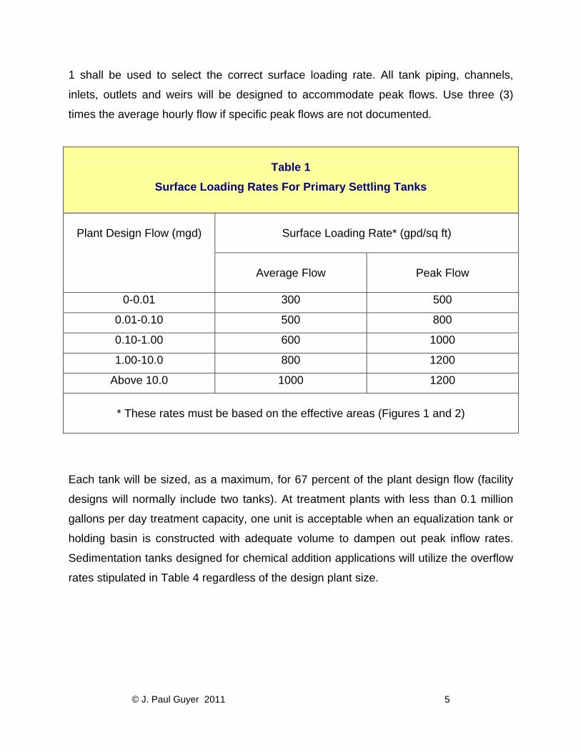
1 shall be used to select the correct surface loading rate. All tank piping, channels,
inlets, outlets and weirs will be designed to accommodate peak flows. Use three (3)
times the average hourly flow if specific peak flows are not documented.
Table 1
Surface Loading Rates For Primary Settling Tanks
Surface Loading Rate* (gpd/sq ft)
Plant Design Flow (mgd)
Average Flow
Peak Flow
0-0.01 300 500
0.01-0.10 500 800
0.10-1.00 600 1000
1.00-10.0 800 1200
Above 10.0 1000 1200
* These rates must be based on the effective areas (Figures 1 and 2)
Each tank will be sized, as a maximum, for 67 percent of the plant design flow (facility
designs will normally include two tanks). At treatment plants with less than 0.1 million
gallons per day treatment capacity, one unit is acceptable when an equalization tank or
holding basin is constructed with adequate volume to dampen out peak inflow rates.
Sedimentation tanks designed for chemical addition applications will utilize the overflow
rates stipulated in Table 4 regardless of the design plant size.
© J. Paul Guyer 2011 5
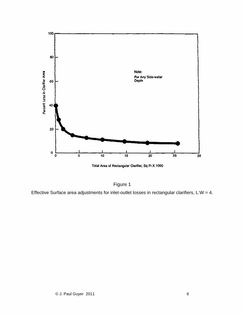
Figure 1
Effective Surface area adjustments for inlet-outlet losses in rectangular clarifiers, L:W = 4.
© J. Paul Guyer 2011 6
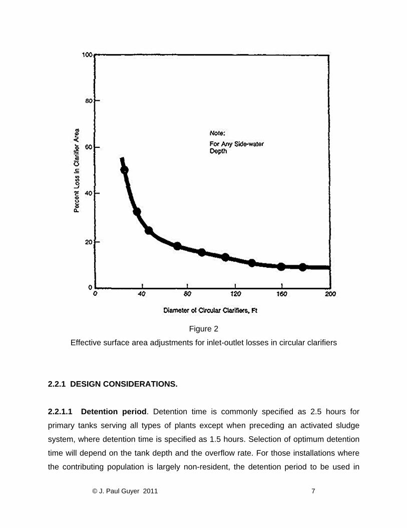
Figure 2
Effective surface area adjustments for inlet-outlet losses in circular clarifiers
2.2.1 DESIGN CONSIDERATIONS.
2.2.1.1 Detention period. Detention time is commonly specified as 2.5 hours for
primary tanks serving all types of plants except when preceding an activated sludge
system, where detention time is specified as 1.5 hours. Selection of optimum detention
time will depend on the tank depth and the overflow rate. For those installations where
the contributing population is largely non-resident, the detention period to be used in
© J. Paul Guyer 2011 7
design of primary settling tanks is 2 hours (based on the average hourly rate for the 8-
hour period when the maximum number of personnel will be contributing to sewage
flow).
2.2.1.2 Weir rate. The overflow loading on weirs will not exceed 5,000 gallons per day
per lineal foot for plants designed for less than 0.1 million gallons per day, or 10,000
gallons per day per lineal foot for plants designed between 0.1 and 1.0 million gallons
per day. Weir loading for plants designed for flows of more than 1.0 million gallons per
day may be higher, but must not exceed 12,000 gallons per day per lineal foot. When
pumping is required, the pump capacity will be related to tank design to avoid excessive
weir loadings.
3. SEDIMENTATION DESIGN FEATURES. Inlets to a settling tank will be designed to
dissipate the inlet velocity, to distribute the flow uniformly, and to prevent short
circuiting. The inlet and outlet channels will be designed for a minimum velocity of 2 feet per second at the average flow rate and will have corners filleted to prevent deposition
and collection of solids. The guidelines shown in Table 2 will be used for designing the
depths of settling tanks.
The use of circular clarifiers to applications greater than 25 feet in diameter should be
limited. Where space permits, at least two units will be provided except as modified by
guidance elsewhere in this discussion.
3.1 RECTANGULAR TANKS. The minimum length of flow from inlet to outlet of a
rectangular tank will be 10 feet in order to prevent short circuiting of flow in the tank. In
existing installations, tank length-to-width ratio varies between 3:1 and 5:1. Tanks will
be designed with a minimum depth of 7 feet except final tanks in activated sludge
plants, which will be designed with a 9-foot minimum depth. Figure 3 illustrates a typical
rectangular sedimentation tank.
© J. Paul Guyer 2011 8
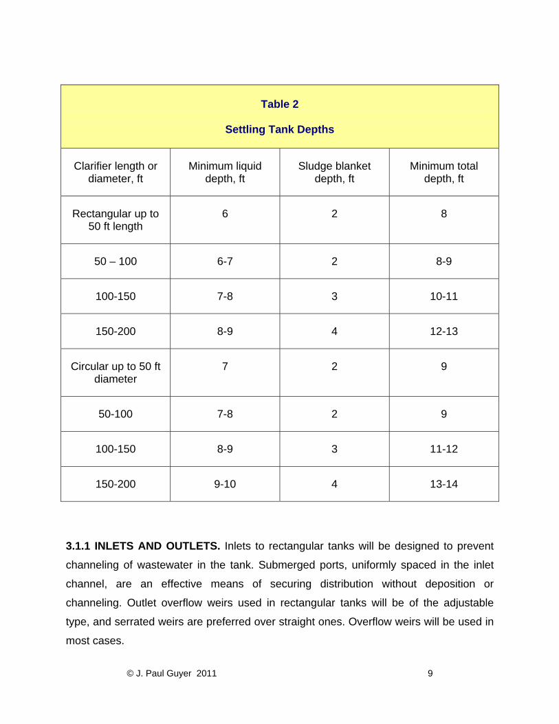
Table 2
Settling Tank Depths
Clarifier length or diameter, ft
Minimum liquid depth, ft
Sludge blanket depth, ft
Minimum total depth, ft
Rectangular up to 50 ft length
6 2 8
50 – 100 6-7 2 8-9
100-150 7-8 3 10-11
150-200 8-9 4 12-13
Circular up to 50 ft diameter
7 2 9
50-100 7-8 2 9
100-150 8-9 3 11-12
150-200 9-10 4 13-14
3.1.1 INLETS AND OUTLETS. Inlets to rectangular tanks will be designed to prevent
channeling of wastewater in the tank. Submerged ports, uniformly spaced in the inlet
channel, are an effective means of securing distribution without deposition or
channeling. Outlet overflow weirs used in rectangular tanks will be of the adjustable
type, and serrated weirs are preferred over straight ones. Overflow weirs will be used in
most cases.
© J. Paul Guyer 2011 9

Figure 3
Typical rectangular primary sedimentation tank
© J. Paul Guyer 2011 10
3.1.2 COLLECTION AND REMOVAL OF SCUM AND SLUDGE. Means for the
collection and removal of scum and sludge are required for all settling tanks. The
removal of scum from the tank will take place immediately ahead of the outlet weirs, and
the equipment may be automatic or manual in operation. Provisions will be made so
that the scum may be discharged to a separate well or sump so that it can be either
sent to the digester or disposed of separately. Rectangular tanks will be provided with
scum troughs with the crest about 1 inch above maximum water surface elevation. For
small installations (less than 1.0 million gallons per day), hand-tilt troughs consisting of
a horizontal, slotted pipe that can be rotated by a lever or screw will be used. Proven
mechanical scum removal devices such as chain-and-flight types may be used for
larger installations. To minimize the accumulation of sludge film on the sides of the
sludge hoppers, a side slope of at least 1½ vertical to 1 horizontal will be used.
Separate sludge wells, into which sludge is deposited from the sludge hoppers and from
which the sludge is pumped, are preferable to direct pump connections with the
hoppers.
3.1.3 CIRCULAR TANKS. Circular tank diameters range from 25 to 150 feet. Side-
water depths are 7 feet as a minimum, and tank floors are deeper at the center.
Flocculator-clarifiers, gaining wide acceptance in recent years, require much greater
depths to accommodate sludge collection mechanisms. Adjustable overflow weirs (V-
notch type) will extend around the entire periphery of the tank. Scum baffles, extending
down to 6 inches below water surface, will be provided ahead of the overflow weir; and
the distance between scum collection troughs will not exceed 75 feet along the
periphery of the clarifier. A circular sludge-removal mechanism with peripheral speeds
of 5 to 8 feet per minute will be provided for sludge collection at the center of the tank.
Figure 4 illustrates a typical circular clarifier.
© J. Paul Guyer 2011 11
3.1.4 TYPICAL DESIGN. The section below illustrates a typical clarifier design.
3.1.4.1 Design requirements and criteria. Design a sedimentation unit to provide for
a sewage flow rate of 4 mgd, with suspended solids concentration of 300 mg/L. The
following conditions apply:
• Surface loading rate = 600 gpd/sq ft
• Suspended solids removal = 60%
• Sludge solids content = 4%
• Sludge specific density = 1.02
3.1.4.2 Calculations and results.
3.1.4.2.1 Calculate total tank surface area:
Surface Area = [Flow Rate]/[Surface Loading Rate]
= 4,000,000 gpd/600 gpd/sq ft = 6,666.7
Use 6,670 sq ft
3.1.4.2.2 Using a depth of 8 ft, calculate total volume:
V = 8 x 6670 = 53,360 cu ft
3.1.4.2.3 This volume can be divided among three rectangular tanks (in parallel), 20 ft
wide and 120 ft long, with a satisfactory length-to-width ratio of 6:1. Two circular tanks
(in parallel), 35 ft in diameter, would also be suitable. This will provide flexibility of
operation during routine or emergency maintenance.
3.1.4.2.4 Calculate weir length requirement, assuming 3 rectangular tanks and
allowable weir loading rate of 15,000 gpd/linear ft.
© J. Paul Guyer 2011 12
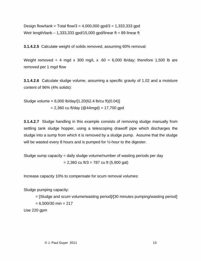
Design flow/tank = Total flow/3 = 4,000,000 gpd/3 = 1,333,333 gpd
Weir length/tank – 1,333,333 gpd/15,000 gpd/linear ft = 89 linear ft
3.1.4.2.5 Calculate weight of solids removed, assuming 60% removal:
Weight removed = 4 mgd x 300 mg/L x .60 = 6,000 lb/day; therefore 1,500 lb are
removed per 1 mgd flow
3.1.4.2.6 Calculate sludge volume, assuming a specific gravity of 1.02 and a moisture
content of 96% (4% solids):
Sludge volume = 6,000 lb/day/[1.20(62.4 lb/cu ft)(0.04)]
= 2,360 cu ft/day (@44mgd) = 17,700 gpd
3.1.4.2.7 Sludge handling in this example consists of removing sludge manually from
settling tank sludge hopper, using a telescoping drawoff pipe which discharges the
sludge into a sump from which it is removed by a sludge pump. Assume that the sludge
will be wasted every 8 hours and is pumped for ½-hour to the digester.
Sludge sump capacity = daily sludge volume/number of wasting periods per day
= 2,360 cu ft/3 = 787 cu ft (5,900 gal)
Increase capacity 10% to compensate for scum removal volumes:
Sludge pumping capacity:
= [Sludge and scum volume/wasting period]/[30 minutes pumping/wasting period]
= 6,500/30 min = 217
Use 220 gpm
© J. Paul Guyer 2011 13
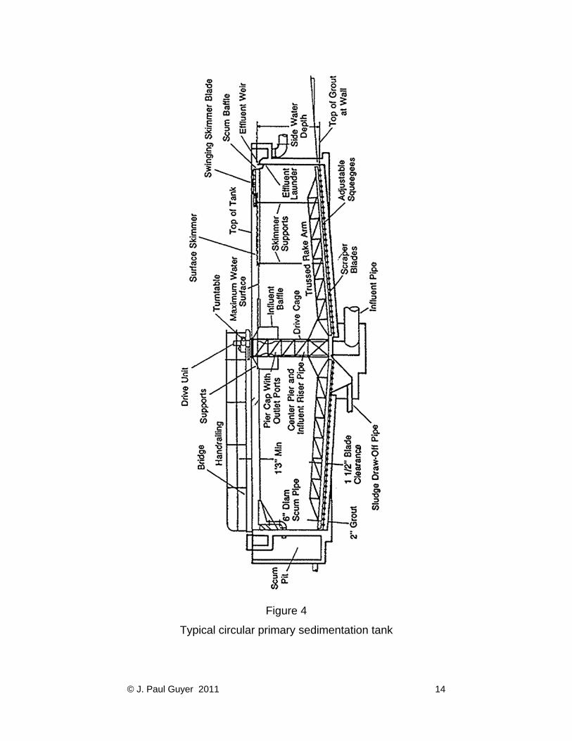
Figure 4
Typical circular primary sedimentation tank
© J. Paul Guyer 2011 14
4. CHEMICAL PRECIPITATION. Chemical treatment of wastewater may be
advantageous when the following conditions exist:
• Wastewater flow and strength are intermittent and vary greatly;
• Space available for additional facilities is limited;
• Industrial waste that would interfere with biological treatment is present;
• The plant is overloaded;
• Plant odor is a problem;
• Phosphorus removal is desired; and
• Biological treatment processes are avoided.
Experience has shown that adding alum, iron or polyelectrolyte at either the primary or
secondary clarifier is effective in increasing pollutant removal efficiencies. Lime addition
is also effective if the effluent pH is adjusted (by recarbonation or acid addition) to
acceptable limits for the subsequent treatment process or for final disposal. Jar tests will
be made to determine optimum coagulants and dosages. Pilot studies should be made
before selecting a coagulant.
4.1 CHEMICAL USED. The EPA Process Design Manual for Suspended Solids
Removal provides criteria for the application of the chemistry and the use of the
chemical precipitants discussed.
4.1.1 ALUMINUM SALTS. Alum (hydrated aluminum sulfate) is the most widely used
aluminum salt. It is effective in many wastewater applications but the precipitate sludge
is difficult to dewater. The primary use of aluminum salts is for the removal of
suspended solids and phosphorus. When alum is used, clarifier overflow rates will not
exceed 600 gallons per day per square foot.
4.1.2 IRON SALTS. Experience has shown that ferric salts are better coagulants than
ferrous salts. Both ferrous and ferric salts are effective in the removal of suspended
© J. Paul Guyer 2011 15
solids and phosphorous, but iron hydroxide carryover in the effluent can affect the
effluent quality.
4.1.3 LIME. Lime addition will improve grit separation, suspended solids removal,
phosphorus removal, and oil and grease removal, as well as reduce odors from dried
sludge. Dosage of lime equal to the suspended solids in wastewater is a common
practice.
4.1.4 POLYELECTROLYTES. These are used frequently, by themselves and in
conjunction with other coagulant aids, to improve the solids-removal performance of
sedimentation units. Their use should be based on jar test results and be reconfirmed
by results in situ. They are more expensive on a unit-weight basis than the other
chemicals in general use, but the required dosage is much lower. Polyelectrolytes—high
molecular weight, water-soluble polymers classified as cationic, anionic, and nonionic—
are highly ionized proprietary compounds. The cationic polymers are positively charged
and will neutralize the negative surface charges on suspended particles, thus permitting
agglomeration. Anionic (negatively charged) and nonionic (no charge) polyelectrolytes
function as flocculants and must be used with a cationic material. The use of
polyelectrolytes has been justified on the basis of improved water quality rather than
cost savings. They can also permit higher flow rates through existing equipment.
4.2 EQUIPMENT FOR CHEMICAL PRECIPITATION. The following brief discussion on
basic equipment required for chemical precipitation is useful for the design of such
systems.
4.2.1 MIXING TANKS. The method for mixing wastewater and the chemical will be a
flash mixing device in a mixing tank designed for 2 minutes detention time. The
propeller will be specified so as to provide for the anticipated maximum flow in the
mixing tank.
© J. Paul Guyer 2011 16
4.2.2 FLOCCULATION. Flocculation tanks will be designed for a detention time of 30
minutes.
4.2.3 SETTLING TANKS. The settling tanks involved in chemical treatment of
wastewater will be designed for a minimum 2 hours detention time or the applicable
maximum overflow rate stipulated in Table 3.
4.3 CHEMICAL PRECIPITATION EXAMPLE PROBLEM. 4.3.1 DESIGN REQUIREMENTS AND CRITERIA. Calculate the sludge production,
using chemical addition in primary sedimentation. Assume that addition of 60 lbs of
ferrous sulfate and 700 lbs/mil gal of lime yields 70 percent suspended solids removal
under the following conditions:
• Flow rate = 4 mgd
• Suspended solids concentration = 300 mg/l
4.3.2 CALCULATIONS AND RESULTS. All interim calculations are computed on the
basis of a flow volume of 1 mil gal.
4.3.2.1 Determine the weight of suspended solids removed:
• Solids weight = (0.70)(300 mg/L)(8.34 [lb/mil gal]/[mg/L]) = 1,750 lb/mil gal
4.3.2.2 Determine weight of ferric hydroxide formed from ferrous sulfate:
• Mol Wt Fe(OH)3 = 106.9
• Mol Wt FeSO4.7H2O = 278.0
• Fe(OH)3 = 60 lb FeSO4.7H2O x (106.9/278.0) = 23 lb/mil gal
© J. Paul Guyer 2011 17
4.3.2.3 Determine weight of CaCO2 formed in reacting with SO4 hardness:
• 2 x Mol Wt CaO = 112
• Mol Wt FeSO4.7H2O = 278
• Mol Wt CaCO2 = 100
• Mol Wt CaO = 56
• CaCO2 weight = 60 lb FeSO4.7H2O x (112/278) x (100/56) = 43 lb/mil gal
CaCO3 formed in reacting with CO and Ca(HCO3)2:
• Mol Wt CaCO = 56
• Mol WT CaCO2 = 100
• 3 x Mol Wt CaCO3 = 300
• 2 x Mol Wt CaO = 112
• CaCO3 = [700 lb CaO – (43 lb CaCO3 x (56/100))] x [300/112] = 1,810 lb/mil gal
Solubility of CaCO3 (25 mg/L):
• CaCO3 dissolved = 25 mg/L x 8.34 (lb/mil gal)/(mg/L) = 208 lb/mil gal
Total CaCO3 weight = 43 + 1,810 – 208 = 1,645 lb/mil gal
Sum total solids weight = 1,750 SS + 23 (Fe(OH)3 + 1,645 CaCO3 = 3,418 lb/mil gal
At flow rate of 4 MGD, the total solids weight = 3,418 lb/mil gal x 4 mgd = 13,672 lb/day
Calculate sludge volume, assuming an overall specific gravity of 1.06 and a moisture
content of 93% (7% solids):
Sludge volume = 3,418 lb/mil gal/(1.06)(62.4 lb/cu ft)(0.07)
= 738 cu ft/mil gal = 2,952 cu ft/day.
© J. Paul Guyer 2011 18
5. IMHOFF TANKS. Imhoff tanks provide removal of settleable solids and the
anaerobic digestion of these solids in the same unit. They are two-level structures which
allow the solids to settle out in the upper level. The settled solids then fall through slots
into the lower level where they undergo digestion. The gas produced during digestion
escapes through the vent areas along the sides of the upper level. The upper level will
be designed for a surface overflow rate of 600 gallons per day per square foot and a
retention period of 3 hours at the average daily flow rate. The bottom of the lower
digestion zone has sides which are sloped 1.4 vertical to 1.0 horizontal. The slot, which
allows the solids to flow from the upper level to the lower level, is a 6-inch opening. An
Imhoff tank can be designed so that a single digestion compartment can receive settled
solids from multiple settling compartments. The digestion compartment should be
designed to provide storage for 6 months accumulation of sludge.
6. SLUDGE CHARACTERISTICS. Table 4 represents typical characteristics of
domestic sewage sludge.
© J. Paul Guyer 2011 19
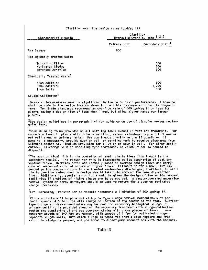
Table 3
© J. Paul Guyer 2011 20
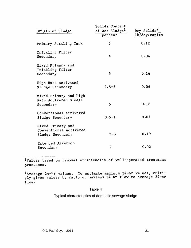
Table 4
Typical characteristics of domestic sewage sludge
© J. Paul Guyer 2011 21
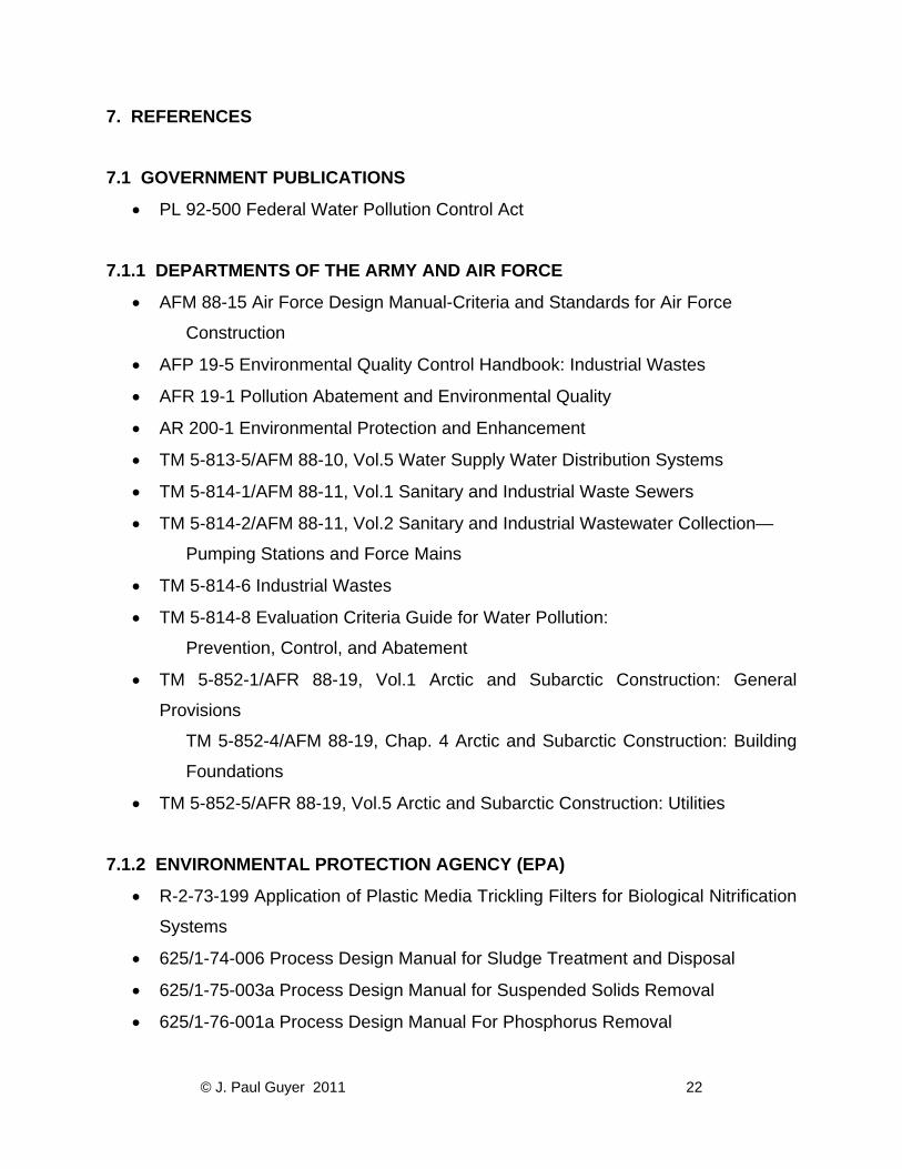
7. REFERENCES
7.1 GOVERNMENT PUBLICATIONS
• PL 92-500 Federal Water Pollution Control Act
7.1.1 DEPARTMENTS OF THE ARMY AND AIR FORCE
• AFM 88-15 Air Force Design Manual-Criteria and Standards for Air Force
Construction
• AFP 19-5 Environmental Quality Control Handbook: Industrial Wastes
• AFR 19-1 Pollution Abatement and Environmental Quality
• AR 200-1 Environmental Protection and Enhancement
• TM 5-813-5/AFM 88-10, Vol.5 Water Supply Water Distribution Systems
• TM 5-814-1/AFM 88-11, Vol.1 Sanitary and Industrial Waste Sewers
• TM 5-814-2/AFM 88-11, Vol.2 Sanitary and Industrial Wastewater Collection—
Pumping Stations and Force Mains
• TM 5-814-6 Industrial Wastes
• TM 5-814-8 Evaluation Criteria Guide for Water Pollution:
Prevention, Control, and Abatement
• TM 5-852-1/AFR 88-19, Vol.1 Arctic and Subarctic Construction: General
Provisions
TM 5-852-4/AFM 88-19, Chap. 4 Arctic and Subarctic Construction: Building
Foundations
• TM 5-852-5/AFR 88-19, Vol.5 Arctic and Subarctic Construction: Utilities
7.1.2 ENVIRONMENTAL PROTECTION AGENCY (EPA)
• R-2-73-199 Application of Plastic Media Trickling Filters for Biological Nitrification
Systems
• 625/1-74-006 Process Design Manual for Sludge Treatment and Disposal
• 625/1-75-003a Process Design Manual for Suspended Solids Removal
• 625/1-76-001a Process Design Manual For Phosphorus Removal
© J. Paul Guyer 2011 22
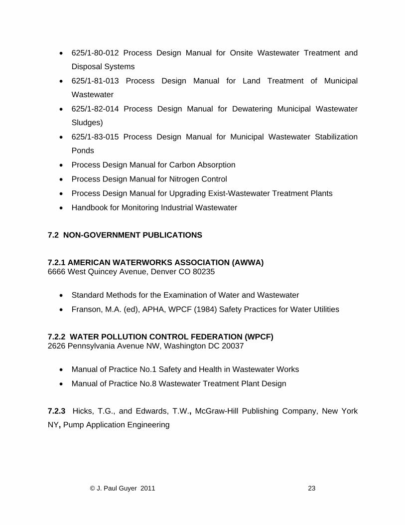
• 625/1-80-012 Process Design Manual for Onsite Wastewater Treatment and
Disposal Systems
• 625/1-81-013 Process Design Manual for Land Treatment of Municipal
Wastewater
• 625/1-82-014 Process Design Manual for Dewatering Municipal Wastewater
Sludges)
• 625/1-83-015 Process Design Manual for Municipal Wastewater Stabilization
Ponds
• Process Design Manual for Carbon Absorption
• Process Design Manual for Nitrogen Control
• Process Design Manual for Upgrading Exist-Wastewater Treatment Plants
• Handbook for Monitoring Industrial Wastewater
7.2 NON-GOVERNMENT PUBLICATIONS 7.2.1 AMERICAN WATERWORKS ASSOCIATION (AWWA) 6666 West Quincey Avenue, Denver CO 80235
• Standard Methods for the Examination of Water and Wastewater
• Franson, M.A. (ed), APHA, WPCF (1984) Safety Practices for Water Utilities
7.2.2 WATER POLLUTION CONTROL FEDERATION (WPCF) 2626 Pennsylvania Avenue NW, Washington DC 20037
• Manual of Practice No.1 Safety and Health in Wastewater Works
• Manual of Practice No.8 Wastewater Treatment Plant Design
7.2.3 Hicks, T.G., and Edwards, T.W., McGraw-Hill Publishing Company, New York
NY, Pump Application Engineering
© J. Paul Guyer 2011 23