introduction to mathematical morphology - ntnu · introduction to mathematical morphology ole...
TRANSCRIPT

1
Introduction to Mathematical Morphology
Ole Christian EidheimDepartment of Computer and Information Science

2
Outline
• Introduction
• Mathematical background
• Dilation and erosion
• Opening and closing
• Hit and miss transform, skeletons
• Geodesic dilation, erotion, and reconstruction
• Watershed segmentation

3
Mathematical Morphology - Introduction
• Based on shapes in the image, not pixel intensities
• Can be viewed as a general image processing framework– Various image processing techniques can be implemented by combining
only a few simple operations• Examples: gradients, distance images, skeletons, noise removal, contrast
enhancement, filling
• Typically used before and after an image segmentation– Exception: watershed segmentation
• All mathematical morphology operations are based on dilation and erosion
• The image processing toolkit in Matlab includes many mathematical morphology operations

4
Mathematical background
• In mathematical morphology we regard the pixel intensities as topographical highs
5
Mathematical background
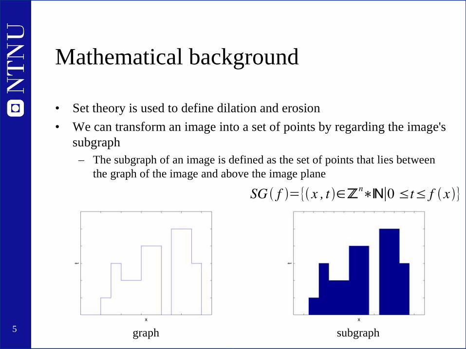
• Set theory is used to define dilation and erosion
• We can transform an image into a set of points by regarding the image's subgraph– The subgraph of an image is defined as the set of points that lies between
the graph of the image and above the image plane
graph subgraph
SG f ={x , t ∈ℤn∗ℕ∣0 ≤t≤ f x}

6
Erosion
• Used to reduces objects in the image
• Definition, binary images:– The positions where a given structure element fits
where Bx means B translated with x,
X is the image, andB is the structure element
BX ={x∣Bx⊆X }

7
Erosion
• Example, binary image

8
Erosion
• Definition, grayscale imagesWe remember the definition for binary images:
Can be rewritten into the intersections of the translated sets X-b:
Which can be extended to also include grayscale images:
BX ={x∣Bx⊆X }
BX =∩b∈B X−b
B f = ∧b∈B f −b

9
Erosion
• Based on
we can define an algorithm to find the erosion of image f:
B f = ∧b∈B f −b
[B f ]x=minb∈B f xb

10
Erosion• Example, grayscale image
f
f-1
f+1
εΒ(f)

11
Dilation
• Used to increase objects in the image
• Definition, binary images:– The positions where a given structure element fits
where Bx means B translated with x,
X is the image, andB is the structure element
BX ={x∣Bx∩X≠∅}

12
Dilation
• Example, binary image

13
Dilation
• Definition, grayscale imagesWe remember the definition for binary images:
Can be rewritten into the unions of the translated sets X-b:
Which can be extended to also include grayscale images:
BX =∪b∈B X−b
B f = ∨b∈B f −b
BX ={x∣Bx∩X≠∅}

14
Dilation
• Based on
we can define an algorithm to find the erosion of image f:
B f = ∨b∈B f −b
[B f ]x=maxb∈B f xb
15
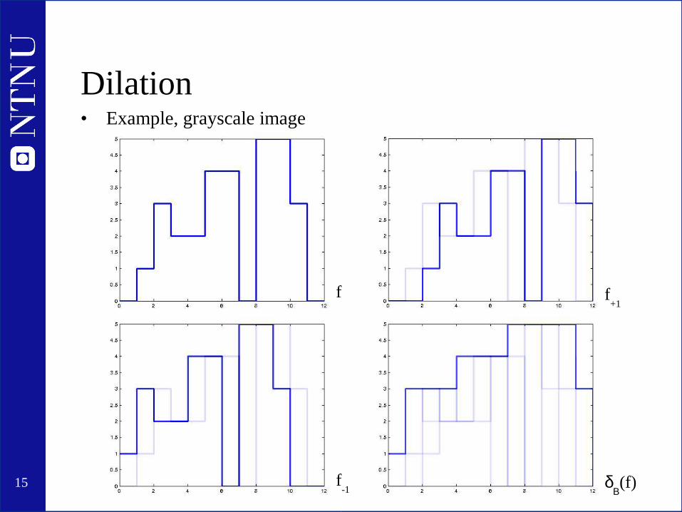
Dilation• Example, grayscale image
f
f-1
f+1
δΒ(f)

16
Dilation
• Example 2, grayscale image

17
Dilation and erosion example

18
Beucher gradient
• Dilation and erosion can be used to extract edge information from images– Example: Beucher gradient
B=B−B

19
Morphological opening
• Used to remove unwanted structures in the image (e.g. noise)
• Morphological opening is simply an erosion followed by a dilation:
• Binary example:
B f = B [B f ]

20
Morphological opening
• Grayscale example

21
Morphological closing
• Is used to merge or fill structures in an image
• Morphological closing is dilation followed by erosion:
• Binary example:
B f = B [B f ]

22
Another example
• How to segment the text from the uneven illumination in the image?

23
Another example
• How to segment the text from the uneven illumination in the image?

24
Another example
• How to segment the text from the uneven illumination in the image?

25
Hit and miss transform
• Used to extract pixels with specific neighbourhood configurations from an image
• Defined only for binary images
• Uses two structure elements B1 and B2 to find a given foreground and background configuration, respectively
• Example:
HMT BX ={x∣B1x⊆X ,B2x⊆XC}

26
Thinning
• Used to shrink objects in binary images
• Differs from erosion in that objects are never completely removed
• Successive thinning until stability results in object skeletons
• Thinning is defined as:
• Structure elements typically used in thinning (rotated 90 degrees 3 times to create 8 structure elements):
THIN X , B=X ∖HMT BX

27
Skeletons
• Minimal representation of objects in an image while retaining the Euler number of the image– The Euler number is the number of objects in an image minus the number of
holes in those objects
• As stated earlier, the skeletons of objects in an image is found by successive thinning until stability

28
Geodesic dilation
• In geodesic dilation the result after dilating the (marker) image f is masked using a mask image g
g f = f ∧g
Marker Mask Result afterdilating the marker image
Masked result
29
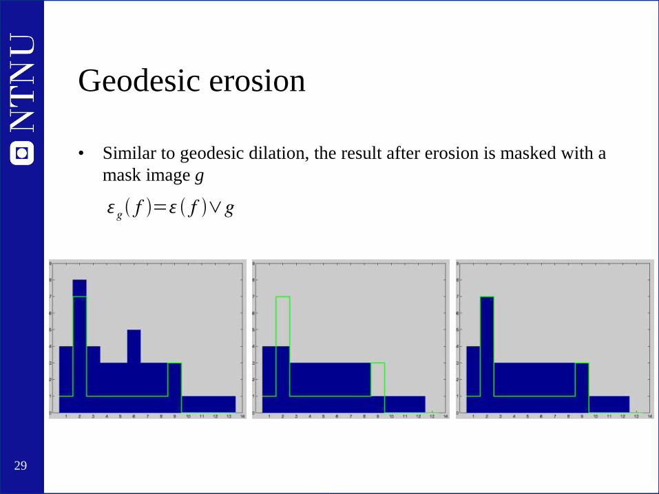
Geodesic erosion
• Similar to geodesic dilation, the result after erosion is masked with a mask image g
g f = f ∨g

30
Geodesic dilation and erosion
• Geodesic dilation repeated n times is expressed and given by
• Likewise, geodesic erosion repeated n times is expressed and given by
gn f =g [g
n−1 f ]
gn f =g [g
n−1 f ]

31
Reconstruction
• Reconstruction is based on geodesic dilation and erosion
• Can for instance be used to – Find and fill local minima or maxima
– Suppress local minima or maxima less than a give size
– Remove noise while not affecting structures of interest
• Reconstruction by dilation is given by:
where
Rg f =gi f
gi f =g
i1 f

32
Reconstruction by dilation, example

33
Reconstruction by erosion
• Reconstruction by erosion is given by
where
Rg* f =g
i f
gi f g
i1 f

34
Reconstruction by erosion, example
35
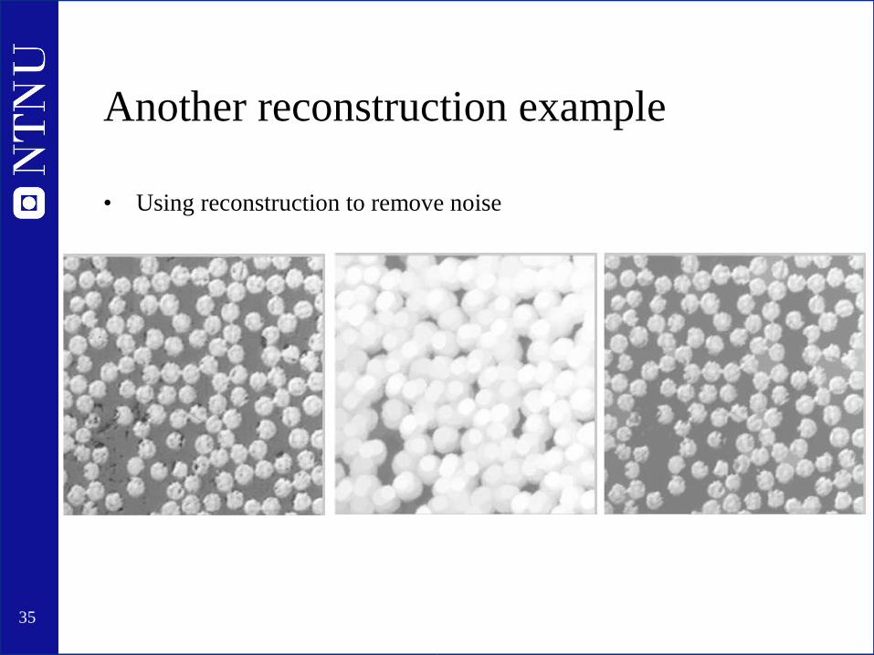
Another reconstruction example
• Using reconstruction to remove noise

36
Watershed segmentation
• Watershed segmentation divides an image into basins and finds the positions where the basins would meet if they were gradually filled

37
Watershed segmentation
Problem: too manylocal minima resultsin oversegmentation

38
Watershed segmentation
• Solution: Use a marker to mark wanted minima, and fill the rest of the local minima

39
Watershed segmentation
• Final segmentation result
40
References
• Pierre Soille, Morphological Image Analysis. Springer-Verlag, 2003.
• Rafael C. Gonzalez, Richard E Woods. Digital Image Processing. Prentice Hall, second edition, 2002.
• Milan Sonka et. al. Image Processing, Analysis and Machine Vision. PWS Publishing, second edition, 1999.