introduction to liquid crystals - wiley...2 introduction to liquid crystals there are quite a number...
TRANSCRIPT

1
1Introduction to Liquid Crystals
1.1. MOLECULAR STRUCTURES AND CHEMICAL COMPOSITIONS
Liquid crystals are wonderful materials. In addition to the solid crystalline and liq-uid phases, liquid crystals exhibit intermediate phases where they flow like liquids,yet possess some physical properties characteristic of crystals. Materials thatexhibit such unusual phases are often called mesogens (i.e., they are mesogenic),and the various phases in which they could exist are termed mesophases.1,2 Thewell-known and widely studied ones are thermotropics, polymerics,3 and lyotrop-ics. As a function of temperature, or depending on the constituents, concentration,substituents, and so on, these liquid crystals exist in many so-called mesophases—nematic, cholesteric, smectic, and ferroelectric. To understand the physical andoptical properties of these materials, we will begin by looking into their constituentmolecules.4
1.1.1. Chemical Structures
Figure 1.1 shows the basic structures of the most commonly occurring liquid crystalmolecules. They are aromatic, and, if they contain benzene rings, they are oftenreferred to as benzene derivatives. In general, aromatic liquid crystal molecules suchas those shown in Figure 1.1 comprise a side chain R, two or more aromatic rings Aand A�, connected by linkage groups X and Y, and at the other end connected to a ter-minal group R�.
Examples of side-chain and terminal groups are alkyl (CnH2n�1), alkoxy (CnH2n�1O),and others such as acyloxyl, alkylcarbonate, alkoxycarbonyl, and the nitro and cyanogroups. The Xs of the linkage groups are simple bonds or groups such as stilbene
(�CH�CH�), ester ( ), tolane (�C�C�), azoxy (�N�N�), Schiff base
(�CH�N�), acetylene (�C�C�), and diacetylene (�C�C�C�C�). The namesof liquid crystals are often fashioned after the linkage group (e.g., Schiff-base liquidcrystal).
C
OO
Liquid Crystals, Second Edition By Iam-Choon KhooCopyright © 2007 John Wiley & Sons, Inc.
JWUS_LC-Khoo_Ch001.qxd 1/11/2007 3:57 PM Page 1
COPYRIG
HTED M
ATERIAL

2 INTRODUCTION TO LIQUID CRYSTALS
There are quite a number of aromatic rings. These include saturated cyclohexaneor unsaturated phenyl, biphenyl, and terphenyl in various combinations.
The majority of liquid crystals are benzene derivatives mentioned previously. Therest include heterocyclics, organometallics, sterols, and some organic salts or fattyacids. Their typical structures are shown in Figures 1.2–1.4.
Heterocyclic liquid crystals are similar in structure to benzene derivatives, withone or more of the benzene rings replaced by a pyridine, pyrimidine, or other similargroups. Cholesterol derivatives are the most common chemical compounds thatexhibit the cholesteric (or chiral nematic) phase of liquid crystals. Organometallic
Figure 1.1. Molecular structure of a typical liquid crystal.
Figure 1.2. Molecular structure of a heterocyclic liquid crystal.
Figure 1.3. Molecular structure of an organometallic liquid crystal.
Figure 1.4. Molecular structure of a sterol.
JWUS_LC-Khoo_Ch001.qxd 1/11/2007 3:57 PM Page 2

compounds are special in that they contain metallic atoms and possess interestingdynamical and magneto-optical properties.4
All the physical and optical properties of liquid crystals are governed by the prop-erties of these constituent groups and how they are chemically synthesized together.Dielectric constants, elastic constants, viscosities, absorption spectra, transition tem-peratures, existence of mesophases, anisotropies, and optical nonlinearities are allconsequences of how these molecules are engineered. Since these molecules arequite large and anisotropic, and therefore very complex, it is practically impossibleto treat all the possible variations in the molecular architecture and the resultingchanges in the physical properties. Nevertheless, there are some generally applicableobservations on the dependence of the physical properties on the molecular con-stituents. These will be highlighted in the appropriate sections.
The chemical stability of liquid crystals depends very much on the central linkagegroup. Schiff-base liquid crystals are usually quite unstable. Ester, azo, and azoxycompounds are more stable, but are also quite susceptible to moisture, temperaturechange, and ultraviolet (UV) radiation. Compounds without a central linkage groupare among the most stable liquid crystals ever synthesized. The most widely studiedone is pentylcyanobiphenyl (5CB), whose structure is shown in Figure 1.5. Othercompounds such as pyrimide and phenylcyclohexane are also quite stable.
1.2. ELECTRONIC PROPERTIES
1.2.1. Electronic Transitions and Ultraviolet Absorption
The electronic properties and processes occurring in liquid crystals are decidedlargely by the electronic properties of the constituent molecules. Since liquid crystalconstituent molecules are quite large, their energy level structures are rather com-plex. As a matter of fact, just the process of writing down the Hamiltonian for an iso-lated molecule itself can be a very tedious undertaking. To also take into accountinteractions among the molecular groups and to account for the difference betweenindividual molecules’ electronic properties and the actual liquid crystals’ responseswill be a monumental task. It is fair to say that existing theories are still not suffi-ciently precise in relating the molecular structures and the liquid crystal responses.We shall limit ourselves here to stating some of the well-established results, mainlyfrom molecular theory and experimental observations.
In essence, the basic framework of molecular theory is similar to that described inChapter 10, except that much more energy levels, or bands, are involved. In general,
ELECTRONIC PROPERTIES 3
Figure 1.5. Molecular structure of pentylcyanobiphenyl (5CB).
JWUS_LC-Khoo_Ch001.qxd 1/11/2007 3:57 PM Page 3

the energy levels are referred to as orbitals. There are �, n, and � orbitals, with theirexcited counterparts labeled as �*, n*, and �*, respectively. The energy differencesbetween these electronic states which are connected by dipole transitions give the so-called resonant frequencies (or, if the levels are so large that bands are formed, giverise to absorption bands) of the molecule; the dependence of the molecular suscepti-bility on the frequency of the probing light gives the dispersion of the optical dielec-tric constant (see Chapter 10).
Since most liquid crystals are aromatic compounds, containing one or more aro-matic rings, the energy levels or orbitals of aromatic rings play a major role. In par-ticular, the � → �* transitions in a benzene molecule have been extensively studied.Figure 1.6 shows three possible � → �* transitions in a benzene molecule.
In general, these transitions correspond to the absorption of light in the near-UVspectral region (� 200 nm). These results for a benzene molecule can also be used tointerpret the absorption of liquid crystals containing phenyl rings. On the other hand,in a saturated cyclohexane ring or band, usually only � electrons are involved. The � → �* transitions correspond to the absorption of light of shorter wavelength (� 180 nm) in comparison to the � → �* transition mentioned previously.
These electronic properties are also often viewed in terms of the presence orabsence of conjugation (i.e., alternations of single and double bonds, as in the case ofa benzene ring). In such conjugated molecules the � electron’s wave function is delo-calized along the conjugation length, resulting in the absorption of light in a longerwavelength region compared to, for example, that associated with the � electron incompounds that do not possess conjugation. Absorption data and spectral depend-ence for a variety of molecular constituents, including phenyl rings, biphenyls,terphenyls, tolanes, and diphenyl-diacetylenes, may be found in Khoo and Wu.5
1.2.2. Visible and Infrared Absorption
From the preceding discussion, one can see that, in general, liquid crystals are quiteabsorptive in the UV region, as are most organic molecules. In the visible and near-infrared regimes (i.e., from 0.4 to 5 �m), there are relatively fewer absorption bands,and thus liquid crystals are quite transparent in these regimes.
4 INTRODUCTION TO LIQUID CRYSTALS
Figure 1.6. � → �* electronic transitions in a benzene molecule.
JWUS_LC-Khoo_Ch001.qxd 1/11/2007 3:57 PM Page 4

As the wavelength is increased toward the infrared (e.g., � 9 �m), rovibrationaltransitions begin to dominate. Since rovibrational energy levels are omnipresent inall large molecules, in general, liquid crystals are quite absorptive in the infraredregime.
The spectral transmission dependence of two typical liquid crystals is shown inFigures 1.7a and 1.7b. The absorption coefficient � in the ultraviolet (� 0.2 �m)regime is on the order of 103 cm�1; in the visible (� 0.5 �m) regime, � � 100 cm�1;in the near-infrared (� 10 �m) regime, � � 102 cm�1; and in the infrared (� 10 �m)regime, � � 102 cm�1. There are, of course, large variations among the thousands ofliquid crystals “discovered” or engineered so far, hence it is possible to identify liquid crystals with the desired absorption/transparency for a particular wavelengthof interest.
Outside the far-infrared regime, e.g., in the microwave region, there have alsobeen active studies.6 At the 20–60 GHz region, for example, liquid crystals continueto exhibit sizable birefringence. Studies have shown that for a typical liquid crystalsuch as E7, the dielectric permittivities for extraordinary and ordinary waves are
ELECTRONIC PROPERTIES 5
Figure 1.7. Transmission spectra of nematic liquid crystals: (a) 5CB and (b) MBBA.
JWUS_LC-Khoo_Ch001.qxd 1/11/2007 3:57 PM Page 5

�e � 3.17 (refractive index ne � 1.78) and �0 � 2.72 (refractive index n0 � 1.65),respectively, i.e., a birefringence of �n � 0.13.
1.3. LYOTROPIC, POLYMERIC, AND THERMOTROPICLIQUID CRYSTALS
One can classify liquid crystals in accordance with the physical parameters control-ling the existence of the liquid crystalline phases. There are three distinct types of liq-uid crystals: lyotropic, polymeric, and thermotropic. These materials exhibit liquidcrystalline properties as a function of different physical parameters and environments.
1.3.1. Lyotropic Liquid Crystals
Lyotropic liquid crystals are obtained when an appropriate concentration of a materialis dissolved in some solvent. The most common systems are those formed by water andamphiphilic molecules (molecules that possess a hydrophilic part that interactsstrongly with water and a hydrophobic part that is water insoluble) such as soaps, deter-gents, and lipids. Here the most important variable controlling the existence of the liq-uid crystalline phase is the amount of solvent (or concentration). There are quite anumber of phases observed in such water-amphiphilic systems, as the composition andtemperature are varied; some appear as spherical micelles, and others possess orderedstructures with one-, two-, or three-dimensional positional order. Examples of thesekinds of molecules are soaps (Fig. 1.8) and various phospholipids like those present incell membranes. Lyotropic liquid crystals are of interest in biological studies.2
1.3.2. Polymeric Liquid Crystals
Polymeric liquid crystals are basically the polymer versions of the monomers dis-cussed in Section 1.1. There are three common types of polymers, as shown inFigures 1.9a–1.9c, which are characterized by the degree of flexibility. The vinyltype (Fig. 1.9a) is the most flexible; the Dupont Kevlar polymer (Fig. 1.9b) is semi-rigid; and the polypeptide chain (Fig. 1.9c) is the most rigid. Mesogenic (or liquid
6 INTRODUCTION TO LIQUID CRYSTALS
Figure 1.8. Chemical structure and cartoon representation of sodium dodecylsulfate (soap) formingmicelles.
JWUS_LC-Khoo_Ch001.qxd 1/11/2007 3:57 PM Page 6

crystalline) polymers are classified in accordance with the molecular architecturalarrangement of the mesogenic monomer. Main-chain polymers are built up by join-ing together the rigid mesogenic groups in a manner depicted schematically inFigure 1.10a; the link may be a direct bond or some flexible spacer. Liquid crystalside-chain polymers are formed by the pendant side attachment of mesogenicmonomers to a conventional polymeric chain, as depicted in Figure 1.10b. A goodaccount of polymeric liquid crystals may be found in Ciferri et al.3 In general,polymeric liquid crystals are characterized by much higher viscosity than that ofmonomers, and they appear to be useful for optical storage applications.
1.3.3. Thermotropic Liquid Crystals: Nematics, Cholesterics, and Smectics
The most widely used liquid crystals, and extensively studied for their linear as wellas nonlinear optical properties, are thermotropic liquid crystals. They exhibit variousliquid crystalline phases as a function of temperature. Although their molecularstructures, as discussed in Section 1.1, are, in general, quite complicated, they are
LYOTROPIC, POLYMERIC, AND THERMOTROPIC LIQUID CRYSTALS 7
Figure 1.9. Three different types of polymeric liquid crystals. (a) Vinyl type; (b) Kevlar polymer; (c) polypeptide chain.
JWUS_LC-Khoo_Ch001.qxd 1/11/2007 3:57 PM Page 7

often represented as “rigid rods.” These rigid rods interact with one another and formdistinctive ordered structures. There are three main classes of thermotropic liquidcrystals: nematic, cholesteric, and smectic. There are several subclassifications ofsmectic liquid crystals in accordance with the positional and directional arrange-ments of the molecules.
These mesophases are defined and characterized by many physical parameters suchas long- and short-range order, orientational distribution functions, and so on. They areexplained in greater detail in the following chapters. Here we continue to use the rigid-rod model and pictorially describe these phases in terms of their molecular arrangement.
Figure 1.11a depicts schematically the collective arrangement of the rodlike liq-uid crystal molecules in the nematic phase. The molecules are positionally random,very much like liquids; x-ray diffraction from nematics does not exhibit any diffrac-tion peak. These molecules are, however, directionally correlated; they are aligned ina general direction defined by a unit vector ñ, the so-called director axis.
In general, nematic molecules are centrosymmetric; their physical properties arethe same in the �n� and the �n� directions. In other words, if the individual moleculescarry a permanent electric dipole (such a polar nature is typically the case), they willassemble in such a way that the bulk dipole moment vanishes.
Cholesterics, now often called chiral nematic liquid crystals, resemble nematic liq-uid crystals in all physical properties except that the molecules tend to align in a heli-cal manner as depicted in Figure 1.11b. This property results from the synthesis ofcholesteric liquid crystals; they are obtained by adding a chiral molecule to a nematicliquid crystal. Some materials, such as cholesterol esters, are naturally chiral.
Smectic liquid crystals, unlike nematics, possess positional order; that is, the posi-tion of the molecules is correlated in some ordered pattern. Several subphases ofsmectics have been “discovered,” in accordance with the arrangement or ordering ofthe molecules and their structural symmetry properties.1,2 We discuss here three rep-resentative ones: smectic-A, smectic-C, and smectic-C* (ferroelectrics).
8 INTRODUCTION TO LIQUID CRYSTALS
Figure 1.10. Polymeric liquid crystals: (a) main chain and (b) side chain.
JWUS_LC-Khoo_Ch001.qxd 1/11/2007 3:57 PM Page 8

Figure 1.12a depicts the layered structure of a smectic-A liquid crystal. In eachlayer the molecules are positionally random, but directionally ordered with their longaxis normal to the plane of the layer. Similar to nematics, smectic-A liquid crystalsare optically uniaxial, that is, there is a rotational symmetry around the director axis.
The smectic-C phase is different from the smectic-A phase in that the material isoptically biaxial, and the molecular arrangement is such that the long axis is tiltedaway from the layer normal z� (see Fig. 1.12b).
In smectic-C* liquid crystals, as depicted in Figure 1.l2c, the director axis n� istilted away from the layer normal z� and “precesses” around the z� axis in successivelayers. This is analogous to cholesterics and is due to the introduction of optical-active or chiral molecules to the smectic-C liquid crystals.
Smectic-C* liquid crystals are interesting in one important respect—namely, thatthey comprise a system that permits, by the symmetry principle, the existence of aspontaneous electric polarization. This can be explained simply in the following way.
The spontaneous electric polarization p� is a vector and represents a breakdown ofsymmetry; that is, there is a directional preference. If the liquid crystal properties areindependent of the director axis n� direction (i.e., �n� is the same as �n� ), p� , if it exists,must be locally perpendicular to n� . In the case of smectic-A, which possesses rotationalsymmetry around n� , p� must therefore be vanishing. In the case of smectic-C, there is areflection symmetry (mirror symmetry) about the plane defined by the n� and z� axes, sop� is also vanishing.
This reflection symmetry is broken if a chiral center is introduced to the molecule,resulting in a smectic-C* system. By convention, p� is defined as positive if it is alongthe direction of z� � n� , and as negative otherwise. Figure 1.12c shows that since n�precesses around z� , p� also precesses around z� . If, by some external field, the helical
LYOTROPIC, POLYMERIC, AND THERMOTROPIC LIQUID CRYSTALS 9
Figure 1.11. Molecular alignments of liquid crystals: (a) nematic and (b) cholesteric or chiral nematic.
JWUS_LC-Khoo_Ch001.qxd 1/11/2007 3:57 PM Page 9

structure is unwound and n� points in a fixed direction, as in Figure 1.12d, then p� willpoint in one direction. Clearly, this and other director axis reorientation processes areaccompanied by considerable change in the optical refractive index and other prop-erties of the system, and they can be utilized in practical electro- and opto-opticalmodulation devices. A detailed discussion of smectic liquid crystals is given inChapter 4.
1.3.4. Other Liquid Crystalline Phases and Molecular Engineered Structures
Besides those phases mentioned above, many other phases of liquid crystalssuch as smectic G, H, I, F,…,Q,..., and cholesteric blue phase have been identi-fied,2,7,8 to name a few. Numerous new molecular engineered liquid crystalline
10 INTRODUCTION TO LIQUID CRYSTALS
Figure 1.12. Molecular arrangements of liquid crystals: (a) smectic-A, (b) smectic-C, (c) smectic-C* orferroelectric, and (d) unwound smectic-C*.
JWUS_LC-Khoo_Ch001.qxd 1/11/2007 3:57 PM Page 10

compounds/structures have also emerged.9,10 Figure 1.13 shows, for example, theshuttlecock-shaped liquid crystal formed by incorporating fullerene C60 to variouscrystals and liquid crystals reported by Sawamura et al.9
1.4. MIXTURES AND COMPOSITES
In general, temperature ranges for the various mesophases of pure liquid crystals arequite limited. This and other physical limitations impose severe shortcomings on thepractical usage of these materials. Accordingly, while much fundamental research isstill performed with pure liquid crystals, industrial applications employ mostly mix-tures, composites, or specially doped liquid crystals with tailor-made physical andoptical properties. Current progress and large-scale application of liquid crystals inoptical technology are largely the result of tremendous advances in such new-mate-rial development efforts.
There are many ways and means of modifying a liquid crystal’s physical proper-ties. At the most fundamental level, various chemical groups such as bonds or atomscan be substituted into a particular class of liquid crystals. A good example is thecyanobiphenyl homologous series nCB (n�1, 2, 3,…). As n is increased throughsynthesis, the viscosities, anisotropies, molecular sizes, and many other parametersare greatly modified. Some of these physical properties can also be modified by substitution. For example, the hydrogen in the 2, 3, and 4 positions of the phenyl ringmay be substituted by some fluoro (F) or chloro (Cl) group.11
MIXTURES AND COMPOSITES 11
Figure 1.13. Shuttlecock-shaped liquid crystal formed by incorporating fullerene C60 to various liquidcrystals reported.9
JWUS_LC-Khoo_Ch001.qxd 1/11/2007 3:57 PM Page 11

Besides these molecular synthesis techniques, there are other physical processesthat can be employed to dramatically improve the performance characteristics of liq-uid crystals. In the following sections we describe three well-developed ones, focus-ing our discussion on nematic liquid crystals.
1.4.1. Mixtures
A large majority of liquid crystals in current device usage are eutectic mixtures oftwo or more mesogenic substances. A good example is E7 (from EM Chemicals),which is a mixture of four liquid crystals (see Fig. 1.14).
The optical properties, dielectric anisotropies, and viscosities of E7 are very dif-ferent from those of the individual mixture constituents. Creating mixtures is an art,guided of course by some scientific principles.11
One of the guiding principles for making the right mixture can be illustrated bythe exemplary phase diagram of two materials with different melting (i.e., crystal →nematic) and clearing (i.e., nematic → isotropic) points, as shown in Figure 1.15.Both substances have small nematic ranges (Ti�Tn and Ti��Tn�). When mixed at theright concentration,4 however, the nematic range (Ti
m�Tnm) of the mixture can be
several magnitudes larger.If the mixture components do not react chemically with one another, clearly their
bulk physical properties, such as dielectric constant, viscosity, and anisotropy, aresome weighted sum of the individual responses; that is, the physical parameter �m ofthe mixture is related to the individual responses’ �i’s by �m � �ci�i, where ci is thecorresponding molar fraction. However, because of molecular correlation effects andthe critical dependence of the constituents on their widely varying transition temper-atures and other collective effects, the simple linear additive representation of themixture’s response is at best a rough approximation. In general, one would expectthat optical and other parameters (e.g., absorption lines or bands), which depend
12 INTRODUCTION TO LIQUID CRYSTALS
Figure 1.14. Molecular structures of the four constituents making up the liquid crystal E7 (from EMChemicals).
JWUS_LC-Khoo_Ch001.qxd 1/11/2007 3:57 PM Page 12

largely on the electronic responses of individual molecules, will follow the simpleadditive rule more closely than physical parameters (e.g., viscosities), which arehighly dependent on intermolecular forces.
In accordance with the foregoing discussion, liquid crystal mixtures formed bydifferent concentrations of the same set of constituents should be regarded as physi-cally and optically different materials.
1.4.2. Dye-Doped Liquid Crystals
From the standpoint of optical properties, the doping of liquid crystals by appropri-ately dissolved concentrations and types of dyes clearly deserves special attention.The most important effect of dye molecules on liquid crystals is the modification oftheir well-known linear, and more recently observed nonlinear, optical properties(see Chapters 8 and 12).
An obvious effect of dissolved dye is to increase the absorption of a particular liq-uid crystal at some specified wavelength region. If the dye molecules undergo somephysical or orientational changes following photon absorption, they could also affectthe orientation of the host liquid crystal, giving rise to nonlinear or storage-type opti-cal effects12 (see Chapter 8).
In linear optical and electro-optical applications, another frequently employed effectis the so-called guest–host effect. This utilizes the fact that the absorption coefficientsof the dissolved dichroic dyes are different for optical fields polarized parallel or per-pendicular to the long (optical) axis of the dye molecule. In general, a dichroic dye mol-ecule absorbs much more for optical field polarization parallel to its long axis than foroptical field polarization perpendicular to its long axis. These molecules are generallyelongated in shape and can be oriented and reoriented by the host nematic liquid crys-tals. Accordingly, the transmission of the cell can be switched with the application ofan external field (see Fig. 1.16).
MIXTURES AND COMPOSITES 13
Figure 1.15. Phase diagram of the mixture of two liquid crystals.
JWUS_LC-Khoo_Ch001.qxd 1/11/2007 3:57 PM Page 13

1.4.3. Polymer-Dispersed Liquid Crystals
Just as the presence of dye molecules modifies the absorption characteristics of liq-uid crystals, the presence of a material interdispersed in the liquid crystals of a dif-ferent refractive index modifies the scattering properties of the resulting “mixed”system. Polymer-dispersed liquid crystals are formed by introducing liquid crystalsas micron- or sub-micron-sized droplets into a polymer matrix. The optical indices ofthese randomly oriented liquid crystal droplets, in the absence of an external align-ment field, depend on the liquid crystal–polymer interaction at the boundary, andtherefore assume a random distribution (see Fig. 1.17a). This causes large scattering.Upon the application of an external field, the droplets will be aligned (Fig. 1.17b),and the system will become clear as the refractive index of the liquid crystal dropletsmatches the isotropic polymer backgrounds.
Polymer-dispersed liquid crystals were introduced many years ago.13 There arenow several techniques for preparing such composite liquid crystalline materials,including the phase separation and the encapsulation methods.14 More recently, opti-cal holographic interference methods15–17 have been employed successfully in mak-ing polymer-dispersed liquid crystal photonic crystals (regular array of materials ofdifferent refractive indices). Caputo et al.18 and Strangi et al.19 have also demon-strated one-dimensional (1D) polymer/liquid crystal layered structures that exhibithigh diffraction efficiency as well as laser emission capabilities.
1.5. LIQUID CRYSTAL CELLS AND SAMPLE PREPARATION
Liquid crystals, particularly nematics which are commonly employed in many electro-optical devices, behave physically very much like liquids. Milk is often a good analogy
14 INTRODUCTION TO LIQUID CRYSTALS
Figure 1.16. Alignment of a dichroic dye-doped nematic liquid crystal: (a) before application of switch-ing electric field; (b) switching field on.
JWUS_LC-Khoo_Ch001.qxd 1/11/2007 3:57 PM Page 14

to liquid crystals in such bulk, “unaligned” states. Its crystalline properties becomeapparent when such milky liquids are contained in (usually) flat thin cells. Thealignment of the liquid crystal axis in such cells is essentially controlled by the cellwalls, whose surfaces are treated in a variety of ways to achieve various director axisalignments.
1.5.1. Bulk Thin Film
For nematics, two commonly used alignments are the so-called homogeneous (orplanar) and homeotropic alignments, as shown in Figures 1.18a and 1.18b, respec-tively. To create homeotropic alignment, the cell walls are treated with a surfactantsuch as hexadecyl-trimethyl~ammoniumbromide (HTAB).20 These surfactants arebasically soaps, whose molecules tend to align themselves perpendicular to the walland thus impart the homeotropic alignment to the liquid crystal.
In the laboratory, a quick and effective way to make a homeotropic nematic liquidcrystal sample is as follows: Dissolve 1 part of HTAB in 50 parts of distilled deion-ized water by volume. Clean two glass slides (or other optical flats appropriate forthe spectral region of interest). Dip the slides in the HTAB solution and slowly with-draw them. This effectively introduces a coating of HTAB molecules on the glassslides. The glass slides should then be dried in an oven or by other means. To preparethe nematic liquid crystal sample, prepare a spacer (Mylar or some nonreactive plas-tic) of desirable dimension and thinness and place the spacer on one of the slides. Fillthe inner spacer with the nematic liquid crystal under study (it helps to first warm itto the isotropic phase). Place the second slide on top of this and clamp the two slidestogether. Once assembled, the sample should be left alone, and it will slowly (in afew minutes) settle into a clear homeotropically aligned state.
Planar alignment can be achieved in many ways. A commonly employed method isto first coat the cell wall with some polymer such as polyvinyl alcohol (PVA) and thenrub it unidirectionally with a lens tissue. This process creates elongated stress/strain
LIQUID CRYSTAL CELLS AND SAMPLE PREPARATION 15
Figure 1.17. Schematic depiction of a polymer-dispersed liquid crystal material: (a) in the absence of anexternal alignment field (highly scattered state); (b) when an external alignment field is on (transparent state).
JWUS_LC-Khoo_Ch001.qxd 1/11/2007 3:57 PM Page 15

on the polymer and facilitates the alignment of the long axis of the liquid crystal mol-ecules along the rubbed direction (i.e., on the plane of the cell wall). Another methodis to deposit silicon oxide obliquely onto the cell wall.
In preparing a PVA-coated planar sample in the laboratory, the following techniquehas been proven to be quite reliable. Dissolve chemically pure PVA (which is solid atroom temperature) in distilled deionized water at an elevated temperature (near theboiling point) at a concentration of about 0.2%. Dip the cleaned glass slide into the PVA solution at room temperature and slowly withdraw it, thus leaving a film ofthe solution on the slide. (Alternatively, one could place a small amount of the PVAsolution on the slide and spread it into a thin coating.) The coated slide is then dried inan oven, followed by unidirectional rubbing of its surfaces with a lens tissue. The restof the procedure for cell assembly is the same as that for homeotropic alignment.
Ideally, of course, these cell preparation processes should be performed in a cleanroom and preferably in an enclosure free of humidity or other chemicals (e.g., a nitro-gen-filled enclosure) in order to prolong the lifetime of the sample. Nevertheless, theliquid crystal cells prepared with the techniques outlined previously have beenshown to last several months and can withstand many temperature cyclings throughthe nematic–isotropic phase transition point, provided the liquid crystals used arechemically stable. In general, nematics such as 5CB and E7 are quite stable, whereasp-methoxybenzylidene-p�-n-butylaniline (MBAA) tends to degrade in a few days.
Besides these two standard cell alignments, there are many other variations suchas hybrid, twisted, supertwisted, fingerprint, multidomain vertically aligned, etc.Industrial processing of these nematic cells, as well as the transparent conductivecoating of the cell windows for electro-optical device applications, is understandablymore elaborate.
16 INTRODUCTION TO LIQUID CRYSTALS
Figure 1.18. Nematic liquid crystal cells: (a) homeogeneous (or planar) aligned and (b) homeotropicaligned.
JWUS_LC-Khoo_Ch001.qxd 1/11/2007 3:57 PM Page 16

For chiral nematic liquid crystals, the method outlined previously for a planarnematic cell has been shown to be quite effective. For smectic-A the preparationmethod is similar to that for a homeotropic nematic cell. In this case, however, ithelps to have an externally applied field to help maintain the homeotropic alignmentas the sample (slowly) cools down from the nematic to the smectic phase. The cellpreparation methods for a ferroelectric liquid crystal (FLC), smectic-C* for surfacestabilized FLC (SSFLC) operation, is more complicated as it involves surface stabi-lization.21,22 On the other hand, smectic-A* (Sm-A*) cells for soft-mode FLC(SMFLC) operation are easier to prepare using the methods described above.23
1.5.2. Liquid Crystal Optical Slab Waveguide, Fiber,and Nanostructured Photonic Crystals
Besides the bulk thin film structures discussed in the preceding section, liquid crys-tals could also be fabricated into optical waveguides24–30 or nanostructured photoniccrystals.31
Both slab and cylindrical (fiber) waveguide structures have been investigated. Atypical liquid crystal slab waveguide24,25 is shown in Figure 1.19. A thin film (approx-imately 1 �m) of liquid crystal is sandwiched between two glass slides (of lowerrefractive index than the liquid crystal), one of which has been deposited with anorganic film into which an input laser is introduced via the coupling prism. The laserexcites the transverse electric (TE) and/or transverse magnetic (TM) modes in theorganic film, which are then guided into the nematic liquid crystal region. Using suchoptical waveguides, Whinnery et al.24 and Giallorenzi et al.25 have measured the scat-tering losses in nematic and smectic liquid crystals and introduced electro-optical andintegrated optical switching devices. However, the large losses in nematics (about 20dB/cm) and their relatively slow responses impose serious limitations in practicalintegrated electro-optical applications. The scattering losses in smectic waveguidesare generally much lower, and they may be useful in nonlinear optical applications(see Chapter 10).
Liquid crystal “fibers” are usually made by filling hollow fibers (microcapillaries)made of material of lower indices of refraction.26,27 The microcapillaries are usually
LIQUID CRYSTAL CELLS AND SAMPLE PREPARATION 17
Figure 1.19. Schematic depiction of a liquid crystal slab waveguide structure.
JWUS_LC-Khoo_Ch001.qxd 1/11/2007 3:57 PM Page 17

made of Pyrex or silica glass, whose refractive indices are 1.47 and 1.45, respec-tively. It was reported26 that the scattering losses of the nematic liquid crystal fibercore are considerably reduced for a core diameter smaller than 10 �m; typically, theloss is about 3 dB/cm (compared to 20 dB/cm for a slab waveguide or bulk thin film).Also, the director axis alignment within the core is highly dependent on the liquidcrystals–capillary interface interaction (i.e., the capillary material). In silica or Pyrexcapillaries the nematic director tends to align along the axis of the fiber (Fig. 1.20a),whereas in borosilicate capillaries the nematic director tends to align in a radialdirection, occasionally mixed in with a thread of axially aligned material runningdown the axis of the fiber (Fig. 1.20b).
Fabrications of such fibers with isotropic phase liquid crystals are much eas-ier.27,29 Because of the fluid property and much lower scattering loss, liquid crystalfibers of much longer dimension have been fabricated and shown to exhibit interest-ing nonlinear optical properties; high quality image transmitting fiber arrays28,29
have also been fabricated for passive pulsed laser limiting applications. Other opti-cal devices based on liquid crystal filled photonic crystal (holey) fibers have alsobeen reported.30
Recently, photonic crystals31 in one-, two-, and three-dimensional forms havereceived intense research interest owing to the rich variety of possibilities in terms of
18 INTRODUCTION TO LIQUID CRYSTALS
Figure 1.20. (a) Axial alignment of a nematic liquid crystal cored fiber; (b) mixed radial and axial align-ments of a nematic liquid crystal cored fiber.
JWUS_LC-Khoo_Ch001.qxd 1/11/2007 3:57 PM Page 18
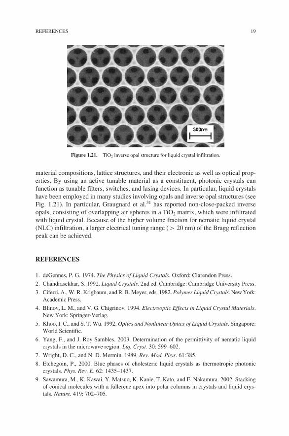
material compositions, lattice structures, and their electronic as well as optical prop-erties. By using an active tunable material as a constituent, photonic crystals canfunction as tunable filters, switches, and lasing devices. In particular, liquid crystalshave been employed in many studies involving opals and inverse opal structures (seeFig. 1.21). In particular, Graugnard et al.31 has reported non-close-packed inverseopals, consisting of overlapping air spheres in a TiO2 matrix, which were infiltratedwith liquid crystal. Because of the higher volume fraction for nematic liquid crystal(NLC) infiltration, a larger electrical tuning range (� 20 nm) of the Bragg reflectionpeak can be achieved.
REFERENCES
1. deGennes, P. G. 1974. The Physics of Liquid Crystals. Oxford: Clarendon Press.
2. Chandrasekhar, S. 1992. Liquid Crystals. 2nd ed. Cambridge: Cambridge University Press.
3. Ciferri, A., W. R. Krigbaum, and R. B. Meyer, eds. 1982. Polymer Liquid Crystals. New York:Academic Press.
4. Blinov, L. M., and V. G. Chigrinov. 1994. Electrooptic Effects in Liquid Crystal Materials.New York: Springer-Verlag.
5. Khoo, I. C., and S. T. Wu. 1992. Optics and Nonlinear Optics of Liquid Crystals. Singapore:World Scientific.
6. Yang, F., and J. Roy Sambles. 2003. Determination of the permittivity of nematic liquidcrystals in the microwave region. Liq. Cryst. 30: 599–602.
7. Wright, D. C., and N. D. Mermin. 1989. Rev. Mod. Phys. 61:385.
8. Etchegoin, P., 2000. Blue phases of cholesteric liquid crystals as thermotropic photoniccrystals. Phys. Rev. E. 62: 1435–1437.
9. Sawamura, M., K. Kawai, Y. Matsuo, K. Kanie, T. Kato, and E. Nakamura. 2002. Stackingof conical molecules with a fullerene apex into polar columns in crystals and liquid crys-tals. Nature. 419: 702–705.
REFERENCES 19
Figure 1.21. TiO2 inverse opal structure for liquid crystal infiltration.
JWUS_LC-Khoo_Ch001.qxd 1/11/2007 3:57 PM Page 19

10. See, for example, Nishiyama, Isa, Jun Yamamoto, John W. Goodby, and Hiroshi Yokoyama.2004. Chirality-induced liquid crystalline nanostructures and their properties. In LiquidCrystals VIII. SPIE Proceedings, Vol. 5518, 201–220 and references therein. I. C. Khoo,Bellingham, WA: SPIE; see also Nishiyama, Isa, Jun Yamamoto, John W. Goodby, andHinshi Yokoyama. 2002. J. Mater. Chem. 12: 1709–1716.
11. Gray, G. W., M. Hird, and K. J. Toyne. 1991. The synthesis of several lateral difluorosub-stituted 4,4-dialkyl- and 4,4-alkoxyalkyl-terphenyls. Mol. Cryst. Liq. Cryst. 204:43; seealso Wu, S. T., D. Coates, and E. Bartmann. 1991. Physical properties of chlorinated liq-uid crystals. Liq. Cryst. 10:635.
12. See, for example, Khoo, I. C., Min-Yi Shih, M. V. Wood, B. D. Guenther, P. H. Chen, F.Simoni, S. Slussarenko, O. Francescangeli, and L. Lucchetti. 1999. Dye-doped photore-fractive liquid crystals for dynamic and storage holographic grating formation and spatiallight modulation. In IEEE Proceedings Special Issue on Photorefractive Optics:Materials, Devices and Applications. Vol. 87 (11): 1897–1911.
13. Doane, J. W., N. A. Vaz, B. G. Wu, and S. Zumer. 1986. Field controlled light scatteringfrom nematic microdroplets. Appl. Phys. Lett. 48:269.
14. West, J. L. 1988. Phase separation of liquid crystals in polymers. Mol. Cryst. Liq. Cryst.157:428; Urzaic, P. 1986. Polymer dispersed nematic liquid crystal for large area displaysand light valves. J. Appl. Phys. 60:2142.
15. Khoo, I. C., Yana Zhang Williams, B. Lewis, and T. Mallouk, 2005. Photorefractive CdSeand gold nanowire-doped liquid crystals and polymer-dispersed-liquid-crystal photoniccrystals. Mol. Cryst. Liq. Cryst. 446:233–244.
16. Tondiglia, V. P., L. V. Natarajan, R. L. Sutherland, D. Tomlin, and T. J. Bunning. 2002.Holographic formation of electro-optical polymer-liquid crystal photonic crystals. Adv.Mater. 14:187–191.
17. Vita, F., A. Marino, V. Tkachenko, G. Abbate, D.E. Lucchetta, L. Criante, and F. Simoni.2005. Visible and near infrared characterization and modeling of nanosized holographic-polymer dispersed liquid crystals gratings. Phys. Rev. E. 72:011702 and references therein.
18. Caputo, R., L. De Sio, A.V. Sukhov, A. Veltri, and C. Umeton. 2004. Development of anew kind of holographic grating made of liquid crystal films separated by slices of poly-meric material. Opt. Lett. 29:1261.
19. Strangi, G., V. Barna, R. Caputo, A. de Luca, C. Versace, N. Scaramuzza, C. Umeton, andR. Bartolino. 2005. Color tunable distributed feedback organic micro-cavity laser. Phys.Rev. Lett. 94:63903.
20. Jen, S., N. A. Clark, P. S. Pershan, and E. B. Priestley. 1977. Polarized Raman-scatteringstudies of orientational order in uniaxial liquid-crystalline phases. J. Chem Phys.66:4635–4661.
21. Clark, N. A., and S. T. Lagerwall. 1980. Submicrosecond bistable electro-optic switchingin liquid crystals. Appl. Phys. Lett. 36:899.
22. Macdonald, R., J. Schwartz, and H. I. Eichler. Laser-induced optical switching of a ferro-electric liquid crystal. Int. J. Nonlinear Opt. Phys. 1:103; Ouchi, Y., H. Takezoe, and A.Fukuda. 1987. Switching process in ferroelectric liquid crystals: Disclination dynamics ofthe surface stabilized states. Jpn. J. Appl. Phys. 26:1.
23. Anderson, G., I. Dahl, L. Komitov, S. T. Lagerwall, K. Skarp, and B. Stebler. 1989.Device physics of the soft-mode electro-optic effect. J. Appl. Phys. 66:4983.
24. Whinnery, J. R., C. Hu, and Y. S. Kwon. 1977. Liquid crystal waveguides for integratedoptics. IEEE J. Quantum Electron. QE13:262.
20 INTRODUCTION TO LIQUID CRYSTALS
JWUS_LC-Khoo_Ch001.qxd 1/11/2007 3:57 PM Page 20
25. Giallorenzi, G., J. A. Weiss, and J. P. Sheridan. 1976. Light scattering from smectic liquid-crystal waveguides. J. Appl. Phys. 47:1820.
26. Geren, M., and S. J. Madden. 1989. Low loss nematic liquid crystal cored fiber wave-guide. Appl. Opt. 28:5202.
27. Khoo, I. C., H. Li, P. G. LoPresti, and Yu Liang. 1994. Observation of optical limiting andbackscattering of nanosecond laser pulses in liquid crystal fibers. Opt. Lett. 19:530.
28. Khoo, I. C., M. V. Wood, B. D. Guenther, Min-Yi Shih, P. H. Chen, Zhaogen Chen, andXumu Zhang. 1998. Liquid crystal film and nonlinear optical liquid cored fiber array forps-cw frequency agile laser optical limiting application. Opt. Express. 2:471–82.
29. Khoo, I. C., Andres Diaz, and J. Ding. 2004. Nonlinear-absorbing fiber array for largedynamic range optical limiting application against intense short laser pulses. J. Opt. Soc.Am. B. 21:1234–1240.
30. Larsen, Thomas Tanggaard, Anders Bjarklev, David Sparre Hermann, and Jes Broeng.2003. Optical devices based on liquid crystal photonic bandgap fibers. Opt. Express.11:2589–2596.
31. Graugnard, E., J. S. King, S. Jain, C. J. Summers, Y. Zhang-Williams, and I. C. Khoo.2005. Electric field tuning of the Bragg peak in large-pore TiO2 inverse shell opals. Phys.Rev. B. 72:233105; see the references quoted therein for other similar studies.
REFERENCES 21
JWUS_LC-Khoo_Ch001.qxd 1/11/2007 3:57 PM Page 21