introduction to isis - afnog
TRANSCRIPT

© 2009 Cisco Systems, Inc. All rights reserved.ISP Workshops 1
Introduction to ISIS
ISP/IXP Workshops
© 2009 Cisco Systems, Inc. All rights reserved.ISP Workshops 2
IS-IS Standards History
ISO 10589 specifies OSI IS-IS routing protocol for CLNS trafficTag/Length/Value (TLV) options to enhance the protocolA Link State protocol with a 2 level hierarchical architecture.
RFC 1195 added IP supportI/IS-IS runs on top of the Data Link LayerRequires CLNP to be configured
RFC5308 adds IPv6 address family support to IS-IS
RFC5120 defines Multi-Topology concept for IS-ISPermits IPv4 and IPv6 topologies which are not identical

© 2009 Cisco Systems, Inc. All rights reserved.ISP Workshops 3
ISIS Levels
ISIS has a 2 layer hierarchyLevel-2 (the backbone)Level-1 (the areas)
A router can beLevel-1 (L1) routerLevel-2 (L2) routerLevel-1-2 (L1L2) router

© 2009 Cisco Systems, Inc. All rights reserved.ISP Workshops 4
ISIS Levels
Level-1 routerHas neighbours only on the same areaHas a level-1 LSDB with all routing information for the area
Level-2 routerMay have neighbours in the same or other areasHas a Level-2 LSDB with all routing information about inter-area
Level-1-2 routerMay have neighbours on any area.Has two separate LSDBs: level-1 LSDB & level-2 LSDB

© 2009 Cisco Systems, Inc. All rights reserved.ISP Workshops 5
Backbone & Areas
ISIS does not have a backbone area as such (likeOSPF)
Instead the backbone is the contiguous collection ofLevel-2 capable routers
ISIS area borders are on links, not routers
Each router is identified with Network Entity Title (NET)NET is an NSAP where the n-selector is 0

© 2009 Cisco Systems, Inc. All rights reserved.ISP Workshops 6
L1L2
L1L2
L1L2
L1L2
L1L2
L1-only
L2-only
L1-only
Area-2
Area-1
Area-3
Area-4
L1-only
L1-only
L1, L2, and L1L2 Routers

© 2009 Cisco Systems, Inc. All rights reserved.ISP Workshops 7
NSAP and Addressing
NSAP: Network Service Access PointTotal length between 8 and 20 bytesArea Address: variable length field (up to 13 bytes)System ID: defines an ES or IS in an area.NSEL: N-selector. identifies a network service user (transport entity or the ISnetwork entity itself)
NET: the address of the network entity itself

© 2009 Cisco Systems, Inc. All rights reserved.ISP Workshops 8
49.0f01.0002.3333.3333.3333.00
49.0f01.0001.2222.2222.2222.00
49.0f01.0001.1111.1111.1111.00
49.0f01.0004.7777.7777.7777.00
49.0f01.0003.6666.6666.6666.00
49.0f01.0004.8888.8888.8888.00
49.0f01.0002.4444.4444.4444.00
Area 1
Area 3
Area 4
Area 2
An Addressing Example

© 2009 Cisco Systems, Inc. All rights reserved.ISP Workshops 9
Addressing Common Practices
ISPs typically choose NSAP addresses thus:First 8 bits – pick a number (usually 49)Next 16 bits – areaNext 48 bits – router loopback addressFinal 8 bits – zero
Example:NSAP: 49.0001.1921.6800.1001.00Router: 192.168.1.1 (loopback) in Area 1

© 2009 Cisco Systems, Inc. All rights reserved.ISP Workshops 10
Hello PDU IIHs are exchanged between routers to formadjacencies
Area addresses are exchanged in IIH PDUs
ISIS adjacency through IIH
Adjacencies

© 2009 Cisco Systems, Inc. All rights reserved.ISP Workshops 11
Link State PDU (LSP)
Each router creates an LSP and flood it to neighbours
A level-1 router will create level-1 LSP(s)
A level-2 router will create level-2 LSP(s)
A level-1-2 router will createlevel-1 LSP(s) andlevel-2 LSP(s)

© 2009 Cisco Systems, Inc. All rights reserved.ISP Workshops 12
LSP Header
LSPs haveFixed headerTLV coded contents
The LSP header containsLSP-idSequence numberRemaining LifetimeChecksumType of LSP (level-1, level-2)Attached bitOverload bit
© 2009 Cisco Systems, Inc. All rights reserved.ISP Workshops 13
LSP Contents
The LSP contents are coded as TLV (Type, Length,Value)
Area addressesIS neighborsAuthentication Info

© 2009 Cisco Systems, Inc. All rights reserved.ISP Workshops 14
LSDB content
Each router maintains a separate LSDB for level-1 andlevel-2 LSPs
LSP headers and contents
SRM bits: set per interface when router has to flood thisLSP
SSN bits: set per interface when router has to send aPSNP for this LSP

© 2009 Cisco Systems, Inc. All rights reserved.ISP Workshops 15
Flooding of LSPs
New LSPs are flooded to all neighbors
It is necessary that all routers get all LSPs
Each LSP has a sequence number
2 kinds of floodingFlooding on a p2p linkFlooding on LAN

© 2009 Cisco Systems, Inc. All rights reserved.ISP Workshops 16
Flooding on a p2p link
Once the adjacency is established both routers sendCSNP packet
Missing LSPs are sent by both routers if not present inthe received CSNP
Missing LSPs may be requested through PSNP

© 2009 Cisco Systems, Inc. All rights reserved.ISP Workshops 17
Flooding on a LAN
There’s a Designated Router (DIS) DIS election is based on priority
Best practice is to select two routers and give them higher priority –then in case of failure one provides deterministic backup to the other
Tie break is by the highest MAC address DIS has two tasks
Conducting the flooding over the LANCreating and updating a special LSP describing the LAN topology(Pseudonode LSP)
Pseudonode represents LAN (created by the DIS)

© 2009 Cisco Systems, Inc. All rights reserved.ISP Workshops 18
Flooding on a LAN
DIS conducts the flooding over the LAN
DIS multicasts CSNP every 10 seconds
All routers in the LAN check the CSNP against theirown LSDB (and may ask specific re-transmissions withPSNPs)

© 2009 Cisco Systems, Inc. All rights reserved.ISP Workshops 19
Complete Sequence Number PDU
Describes all LSPs in your LSDB (in range)
If LSDB is large, multiple CSNPs are sent
Used at 2 occasionsPeriodic multicast by DIS (every 10 seconds) to synchroniseLSDB over LAN subnetsOn p2p links when link comes up
© 2009 Cisco Systems, Inc. All rights reserved.ISP Workshops 20
Partial Sequence Number PDUs
PSNPs Exchanged on p2p links (ACKs) Two functions
Acknowledge receipt of an LSPRequest transmission of latest LSP
PSNPs describe LSPs by its headerLSP identifierSequence numberRemaining lifetimeLSP checksum

© 2009 Cisco Systems, Inc. All rights reserved.ISP Workshops 21
Area-2 Area-3 Area-1
Rtr-A Rtr-B Rtr-C
Configuration
L1, L2, L1-L2By default cisco routers will be L1L2 routersRouters can be manually configured to behave as
Level-1 only, Level-2 only, Level-1-2This is what most ISPs do
Configuration can be done per interface or at the router level

© 2009 Cisco Systems, Inc. All rights reserved.ISP Workshops 22
Area 49.0001 Area 49.0002
Rtr-C Rtr-B
Rtr-A Rtr-D
L1L2 routers
L1routers
Router-B
interface Loopback0 ip address 192.168.1.1 255.255.255.255!Interface Pos2/0/0 ip address 192.168.222.1 255.255.255.0 ip router isis isis circuit-type level-2!FastEthernet4/0/0 ip address 192.168.120.10 255.255.255.0 ip router isis isis circuit-type level-1!router isis passive-interface Loopback0 net 49.0001.1921.6800.1001.00
Router-A
interface Loopback0 ip address 192.168.1.5 255.255.255.255!interface FastEthernet0/0 ip address 192.168.120.5 255.255.255.0 ip router isis!router isis is-type level-1 passive-interface Loopback0 net 49.0001.1921.6800.1005.00
Configuration for A&B

© 2009 Cisco Systems, Inc. All rights reserved.ISP Workshops 23
Router-C
interface Loopback0 ip address 192.168.2.2 255.255.255.255!Interface Pos1/0/0 ip address 192.168.222.2 255.255.255.0 ip router isis isis circuit-type level-2!interface Fddi3/0 ip address 192.168.111.2 255.255.255.0 ip router isis isis circuit-type level-1!router isis passive-interface Loopback0 net 49.0002.1921.6800.2002.00
Router-D
interface Loopback0 ip address 192.168.2.4 255.255.255.255!interface Fddi6/0 ip address 192.168.111.4 255.255.255.0 ip router isis!router isis is-type level-1 passive-interface Loopback0 net 49.0002.1921.6800.2004.00
Configuration for C&D
Area 49.0001 Area 49.0002
Rtr-C Rtr-B
Rtr-A Rtr-D
L1L2 routers
L1routers

© 2009 Cisco Systems, Inc. All rights reserved.ISP Workshops 24
Adding interfaces to ISIS
To activate ISIS on an interface:interface HSSI 4/0
ip route isis isp-bb
isis circuit-type level-2
To disable ISIS on an interface:router isis isp-bb
passive-interface GigabitEthernet 0/0
Disables CLNS on that interfacePuts the interface subnet address into the LSDB
No ISIS configuration on an interfaceNo CLNS run on interface, no interface subnet in the LSDB

© 2009 Cisco Systems, Inc. All rights reserved.ISP Workshops 25
Adding interfaces to ISIS
Scaling ISIS: passive-interface defaultDisables ISIS processing on all interfaces apart from thosemarked as no-passivePlaces all IP addresses of all connected interfaces into ISISMust be at least one non-passive interface:
router isis isp-bb passive-interface default no passive-interface GigabitEthernet 0/0interface GigabitEthernet 0/0 ip router isis isp-bb isis metric 1 level-2

© 2009 Cisco Systems, Inc. All rights reserved.ISP Workshops 26
Status Commands in ISIS
Show clnsShows the global CLNS status as seen on the router, e.g.
Rtr-B>show clns
Global CLNS Information:
2 Interfaces Enabled for CLNS
NET: 49.0001.1921.6800.1001.00
Configuration Timer: 60, Default Holding Timer: 300, PacketLifetime 64
ERPDU's requested on locally generated packets
Intermediate system operation enabled (forwarding allowed)
IS-IS level-1-2 Router:
Routing for Area: 49.0001

© 2009 Cisco Systems, Inc. All rights reserved.ISP Workshops 27
Status Commands in ISIS
Show clns neighborsShows the neighbour adjacencies as seen by the router:
Rtr-B> show clns neighbors
System Id SNPA Interface State Holdtime Type Protocol
1921.6800.2002 *PPP* PO2/0/0 Up 29 L2 IS-IS
1921.6800.1005 00e0.1492.2c00 Fa4/0/0 Up 9 L1 IS-IS
More recent IOSes replace system ID with routerhostname – ease of troubleshooting
© 2009 Cisco Systems, Inc. All rights reserved.ISP Workshops 28
Status Commands in ISIS
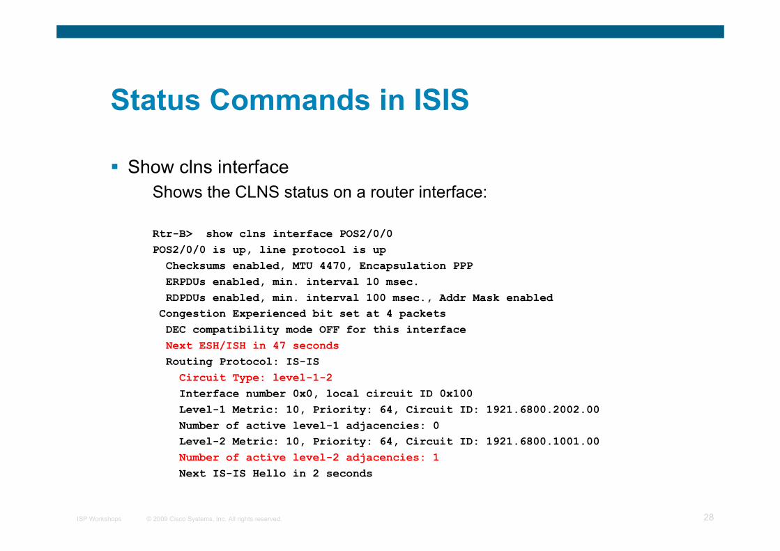
Show clns interfaceShows the CLNS status on a router interface:
Rtr-B> show clns interface POS2/0/0POS2/0/0 is up, line protocol is up Checksums enabled, MTU 4470, Encapsulation PPP ERPDUs enabled, min. interval 10 msec. RDPDUs enabled, min. interval 100 msec., Addr Mask enabled Congestion Experienced bit set at 4 packets DEC compatibility mode OFF for this interface Next ESH/ISH in 47 seconds Routing Protocol: IS-IS Circuit Type: level-1-2 Interface number 0x0, local circuit ID 0x100 Level-1 Metric: 10, Priority: 64, Circuit ID: 1921.6800.2002.00 Number of active level-1 adjacencies: 0 Level-2 Metric: 10, Priority: 64, Circuit ID: 1921.6800.1001.00 Number of active level-2 adjacencies: 1 Next IS-IS Hello in 2 seconds

© 2009 Cisco Systems, Inc. All rights reserved.ISP Workshops 29
Status Commands in ISIS
Show CLNS protocolDisplays the status of the CLNS protocol on the router:
Rtr-B> show clns protocolIS-IS Router: <Null Tag> System Id: 1921.6800.1001.00 IS-Type: level-1-2 Manual area address(es): 49.0001 Routing for area address(es): 49.0001 Interfaces supported by IS-IS: FastEthernet4/0/0 - IP POS2/0/0 - IP Redistributing: static Distance: 110

© 2009 Cisco Systems, Inc. All rights reserved.ISP Workshops 30
Other status commands
“show clns traffic”Shows CLNS traffic statistics and activity for the network
“show isis database”Shows the ISIS link state databasei.e. the “routing table”
© 2009 Cisco Systems, Inc. All rights reserved.ISP Workshops 31
Network Design Issues
As in all IP network designs, the key issue is theaddressing lay-out
ISIS supports a large number of routers in a single area
When using areas, use summary-addresses
>400 routers in the backbone is quite doable

© 2009 Cisco Systems, Inc. All rights reserved.ISP Workshops 32
Network Design Issues
Possible link costDefault on all interface is 10(Compare with OSPF which set cost according to link bandwidth)Manually configured according to routing strategy
Summary address costEqual to the best more specific costPlus cost to reach neighbor of best specific
Backbone has to be contiguousEnsure continuity by redundancy
Area partitioningDesign so that backbone can NOT be partitioned

© 2009 Cisco Systems, Inc. All rights reserved.ISP Workshops 33
Scaling Issues
Areas vs. single areaUse areas where
sub-optimal routing is not an issueareas with one single exit point
Start with L2-only everywhere is a good choiceFuture implementation of level-1 areas will be easierBackbone continuity is ensured from start

© 2009 Cisco Systems, Inc. All rights reserved.ISP Workshops 34
ISIS for IPv6

© 2009 Cisco Systems, Inc. All rights reserved.ISP Workshops 35
IS-IS for IPv6
2 Tag/Length/Values added to introduce IPv6 routing
IPv6 Reachability TLV (0xEC)External bitEquivalent to IP Internal/External Reachability TLV’s
IPv6 Interface Address TLV (0xE8)For Hello PDUs, must contain the Link-Local addressFor LSP, must only contain the non-Link Local address
IPv6 NLPID (0x8E) is advertised by IPv6 enabled routers
© 2009 Cisco Systems, Inc. All rights reserved.ISP Workshops 36
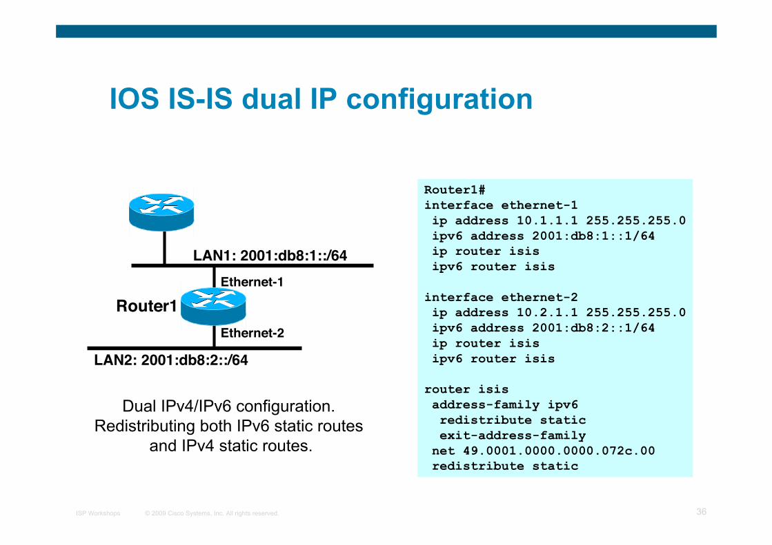
Router1#interface ethernet-1 ip address 10.1.1.1 255.255.255.0 ipv6 address 2001:db8:1::1/64 ip router isis ipv6 router isis
interface ethernet-2 ip address 10.2.1.1 255.255.255.0 ipv6 address 2001:db8:2::1/64 ip router isis ipv6 router isis router isis address-family ipv6 redistribute static exit-address-family net 49.0001.0000.0000.072c.00 redistribute static
LAN1: 2001:db8:1::/64
LAN2: 2001:db8:2::/64
Ethernet-1
Ethernet-2
Router1
Dual IPv4/IPv6 configuration. Redistributing both IPv6 static routes
and IPv4 static routes.
IOS IS-IS dual IP configuration

© 2009 Cisco Systems, Inc. All rights reserved.ISP Workshops 37
On Router2:interface Tunnel0 no ip address ipv6 address 2001:db8:1::2/64 ipv6 address FE80::10:7BC2:B280:11 link-local ipv6 router isis tunnel source 10.42.2.1 tunnel destination 10.42.1.1!router isis net 49.0001.0000.0000.0002.00
On Router1:interface Tunnel0 no ip address ipv6 address 2001:db8:1::1/64 ipv6 address FE80::10:7BC2:ACC9:10 link-local ipv6 router isis tunnel source 10.42.1.1 tunnel destination 10.42.2.1!router isis net 49.0001.0000.0000.0001.00
IPv6Network
IPv6Tunnel
IPv6 Tunnel
IPv6Network
IPv6Network
IS-IS for IPv6 on an IPv6 Tunnelrequires GRE Tunnel; it can’t workwith IPv6 configured tunnel as IS-ISruns directly over the data link layer
IOS Configuration for IS-IS for IPv6 onIPv6 Tunnels over IPv4
IPv6 Tunnel
IPv4Backbone

© 2009 Cisco Systems, Inc. All rights reserved.ISP Workshops 38
Multi-Topology IS-IS extensions
IS-IS for IPv6 assumes that the IPv6 topology is the same as theIPv4 topology
Single SPF running, multiple address familiesSome networks may be like this, but many others are not
Multi-Topology IS-IS solves this problemNew TLV attributes introducedNew Multi-Topology ID #2 for IPv6 Routing TopologyTwo topologies now maintained:
ISO/IPv4 Routing Topology (MT ID #0)IPv6 Routing Topology (MT ID #2)

© 2009 Cisco Systems, Inc. All rights reserved.ISP Workshops 39
Multi-Topology IS-IS extensions
New TLVs attributes for Multi-Topology extensions:Multi-topology TLV: contains one or more multi-topology ID inwhich the router participatesMT Intermediate Systems TLV: this TLV appears as many timesas the number of topologies a node supportsMulti-Topology Reachable IPv4 Prefixes TLV: this TLV appearsas many times as the number of IPv4 announced by an IS for agiven MT IDMulti-Topology Reachable IPv6 Prefixes TLV: this TLV appearsas many times as the number of IPv6 announced by an IS for agiven MT ID
© 2009 Cisco Systems, Inc. All rights reserved.ISP Workshops 40
Area B
LAN1: 2001:db8:1::1/64
LAN2: 2001:db8:2::1/64
Ethernet 1
Ethernet 2
Router1
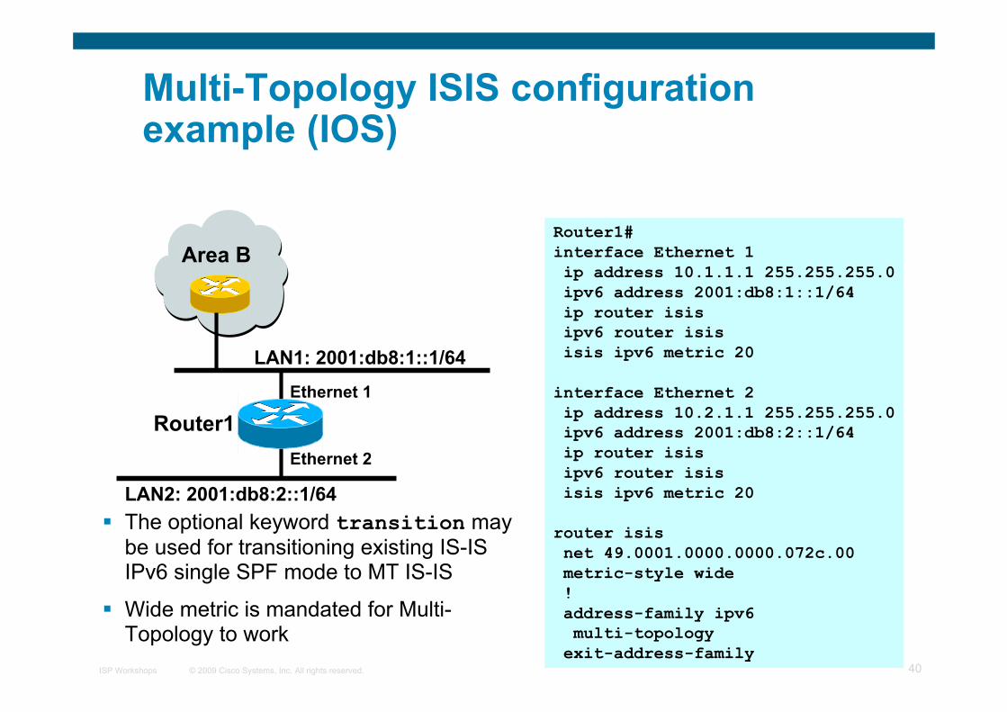
Router1#interface Ethernet 1 ip address 10.1.1.1 255.255.255.0 ipv6 address 2001:db8:1::1/64 ip router isis ipv6 router isis isis ipv6 metric 20
interface Ethernet 2 ip address 10.2.1.1 255.255.255.0 ipv6 address 2001:db8:2::1/64 ip router isis ipv6 router isis isis ipv6 metric 20
router isis net 49.0001.0000.0000.072c.00 metric-style wide ! address-family ipv6 multi-topology exit-address-family
Multi-Topology ISIS configurationexample (IOS)
The optional keyword transition maybe used for transitioning existing IS-ISIPv6 single SPF mode to MT IS-IS
Wide metric is mandated for Multi-Topology to work
© 2009 Cisco Systems, Inc. All rights reserved.ISP Workshops 41
Narrow to Wide Metrics Transition
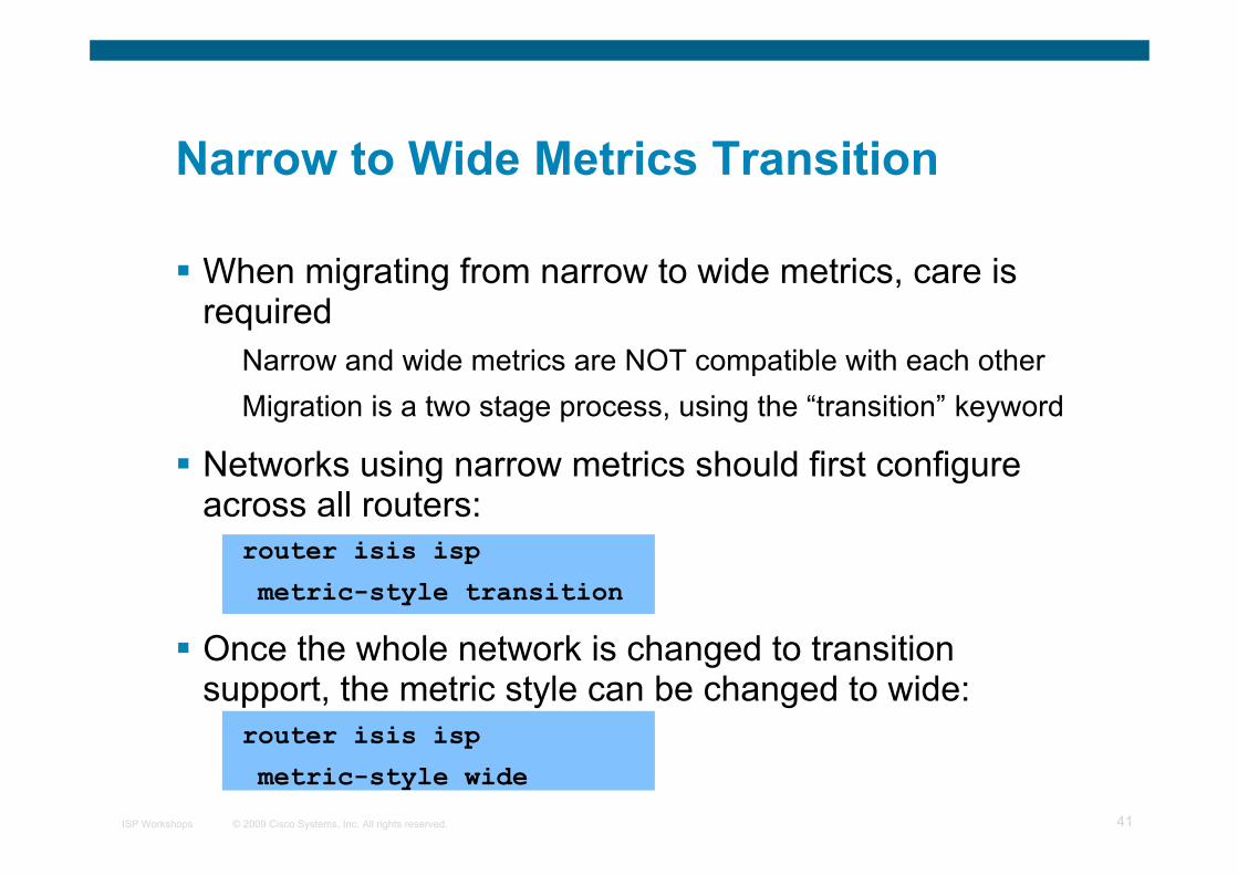
When migrating from narrow to wide metrics, care isrequired
Narrow and wide metrics are NOT compatible with each otherMigration is a two stage process, using the “transition” keyword
Networks using narrow metrics should first configureacross all routers:
router isis isp
metric-style transition
Once the whole network is changed to transitionsupport, the metric style can be changed to wide:
router isis isp
metric-style wide

© 2009 Cisco Systems, Inc. All rights reserved.ISP Workshops 42
ISP common practices
NSAP address constructionArea and loopback address
L2L1-L2 and L1 used later for scaling
Wide metricsNarrow metrics are too limiting
Deploying IPv6 in addition to IPv4Multi-topology is recommended – gives increased flexibilityshould there be future differences in topology

© 2009 Cisco Systems, Inc. All rights reserved.ISP Workshops 43
ISP Best Practices
Extra detailed information

© 2009 Cisco Systems, Inc. All rights reserved.ISP Workshops 44
ISIS neighbour authentication
Create key chains to be used for HMAC-MD5authentication for both Level-1 and Level-2
key chain isis-sec-l1
key 1
key-string xxxxx
key chain isis-sec-l2
key 1
key-string xxxxx

© 2009 Cisco Systems, Inc. All rights reserved.ISP Workshops 45
Setting up Loopback Interface
Create the Loopback interface/Router-IDIt will NOT have IS-IS running on it because it is not a transitinterfaceDisabling IS-IS on it, while announcing the IP prefixes into IS-IS, allows the IS-IS domain to scale because LSP/Hello packetsare not unnecessarily generated for the Loopback interfaceAn IS-IS metric will NOT be set, which will default the Loopbackinterface's metric to zero (0).
interface loopback0
ip address 192.168.0.1 255.255.255.255
ipv6 address 2001:db8:192:168:0:1/128

© 2009 Cisco Systems, Inc. All rights reserved.ISP Workshops 46
Level-1 Interface Configuration
Configure addresses and enable ISIS for IPv4 and IPv6interface gigabitethernet0/1
ip address 192.168.1.1 255.255.255.192
ipv6 address 2001:db8:192:168:1:1/112
!
ip router isis 1
ipv6 router isis 1
Ensure this interfaces runs at Level-1 isis circuit-type level-1

© 2009 Cisco Systems, Inc. All rights reserved.ISP Workshops 47
Level-1 Interface: Metrics & Auth
Set the costs for IPv4 and IPv6interface gigabitethernet0/1
isis metric 400 level-1
isis ipv6 metric 400 level-1
Enable HMAC-MD5 for level-1 isis authentication mode md5 level-1
Associate the key-chain defined earlier isis authentication key-chain isis-sec-l1 level-1
© 2009 Cisco Systems, Inc. All rights reserved.ISP Workshops 48
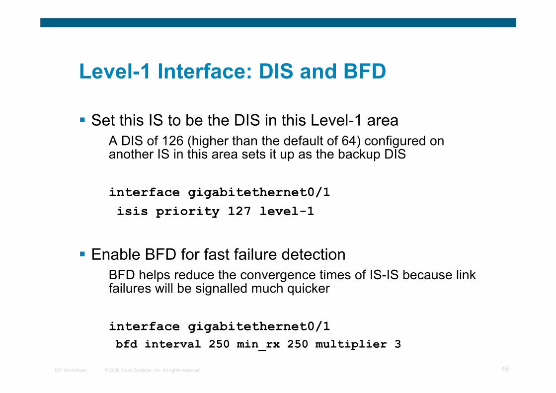
Level-1 Interface: DIS and BFD
Set this IS to be the DIS in this Level-1 areaA DIS of 126 (higher than the default of 64) configured onanother IS in this area sets it up as the backup DIS
interface gigabitethernet0/1 isis priority 127 level-1
Enable BFD for fast failure detectionBFD helps reduce the convergence times of IS-IS because linkfailures will be signalled much quicker
interface gigabitethernet0/1 bfd interval 250 min_rx 250 multiplier 3

© 2009 Cisco Systems, Inc. All rights reserved.ISP Workshops 49
Level-2 interface
This interface is used for a trunk link to another PoP forming part ofyour network-wide backbone
As such it will be a Level-2 interface, making this router a Level-1/Level-2 IS.Metric and authentication are all configured for Level-2interface gigabitethernet0/2 ip address 192.168.2.1 255.255.255.252 ipv6 address 2001:db8:192:168:2:1:/126 ip router isis 1 ipv6 router isis 1 isis circuit-type level-2-only isis metric 400 level-2 isis ipv6 metric 400 level-2 isis authentication mode md5 level-2 isis authentication key-chain isis-sec-l2 level-2

© 2009 Cisco Systems, Inc. All rights reserved.ISP Workshops 50
Level 2 interface: more details
To make this IS-IS BCP more interesting, we will assume this trunklink is a broadcast multi-access link, i.e., Ethernet.
As this is an Ethernet interface, IS-IS will attempt to elect a DISwhen it forms an adjacency
Because it is running as a point-to-point WAN link, with only 2 IS's onthe wire, configuring IS-IS to operate in "point-to-point mode" scalesthe protocol by reducing the link failure detection timesPoint-to-point mode improves convergence times on Ethernet networksbecause it:
Prevents the election of a DIS on the wire,Prevents the flooding process from using CSNP's for databasesynchronizationSimplifies the SPF computations and reduces the IS's memoryfootprint due to a smaller topology database.
int gi0/2 isis network point-to-point

© 2009 Cisco Systems, Inc. All rights reserved.ISP Workshops 51
ISP Best Practices
We now configure parameters specific to the IS-IS routing protocolThis covers both IPv4 and IPv6, as IS-IS supports both IP protocols inthe same implementationrouter isis 1
Create an NETThis is made up of a private AFI (49), an area part, a System ID (takenfrom the padded Loopback interface IP address) and an N-SEL of zero(0). net 49.0001.1921.6800.0001.00
Enable HMAC-MD5 authentication authentication mode md5
authentication key-chain isis-sec-l1 level-1
authentication key-chain isis-sec-l2 level-2

© 2009 Cisco Systems, Inc. All rights reserved.ISP Workshops 52
ISP Best Practices
Enable iSPF (incremental SPF).This, in the long run, reduces CPU demand because SPF calculationsare run only on the affected changes in the SPT.As this is a Level-1/Level-2 router, enable iSPF at both levels 60seconds after the command has been entered into the configuration.Note that IOS only supports iSPF for IPv4. ispf level-1-2 60
Enable wide/extended metric support for IS-IS.IOS, by default, supports narrow metrics, which means you can definecost values between 1-63. This is not scalable.To solve this problem, enable wide metrics, which allows you to definecost values between 1-16777214. metric-style wide

© 2009 Cisco Systems, Inc. All rights reserved.ISP Workshops 53
ISP Best Practices
Increase ISIS default metricDefault value is 10All interfaces in both L1 and L2 have this valueNot useful if configured value is “accidentally” removed - a low priorityinterface could end up taking full load by mistakeConfigure a “very large” value as default metric 100000
Disable IIH padding because on high speed links, it may strainhuge buffers; and on low speed links, it may waste bandwidth andaffect other time sensitive applications, e.g., voice.
Disabling IIH padding is safe because IOS will still pad the first 5 IIH'sto the full MTU to aid in the discovery of MTU mismatches. no hello padding

© 2009 Cisco Systems, Inc. All rights reserved.ISP Workshops 54
ISP Best Practices
Allow the Loopback interface IP address to be carried within IS-IS,while preventing it from being considered in the flooding process.
passive-interface Loopback0
Log changes in the state of the adjacencies. log-adjacency-changes
Tell the IS to ignore LSP's with an incorrect data-link checksum,rather than purge them
Purging LSP's with a bad checksum causes the initiating IS toregenerate that LSP, which could overload the IS if perpetuated in acycleSo rather than purge them, ignore them. ignore-lsp-errors

© 2009 Cisco Systems, Inc. All rights reserved.ISP Workshops 55
ISP Best Practices
Reduce the amount of control traffic, conserving CPU usage forgeneration and refreshing of LSP's.
Do this by increasing the LSP lifetime to its limits. max-lsp-lifetime 65535
Reduce the frequency of periodic LSP flooding of the topology,which reduces link utilization
This is safe because there other mechanisms to guard againstpersistence of corrupted LSP's in the LSDB. lsp-refresh-interval 65000
Customize IS-IS throttling of SPF calculations.Good for when you also use BFD for IS-IS.These are recommended values for fast convergence. spf-interval 5 1 20

© 2009 Cisco Systems, Inc. All rights reserved.ISP Workshops 56
ISP Best Practices
Customize IS-IS throttling of PRC calculations.PRC calculates routes without performing a full SFP calculation.This is done when a change is signaled by another IS, but without acorresponding change in the basic network topology, e.g., the need toreinstall a route in the IS-IS RIB.These are recommended values for fast convergence. prc-interval 5 1 20
Customize IS-IS throttling of LSP generation.These are recommended values for fast convergence. lsp-gen-interval 5 1 20

© 2009 Cisco Systems, Inc. All rights reserved.ISP Workshops 57
ISP Best Practices
Enable IS-IS fast-flooding of LSP's.This tells the IS to always flood the LSP that triggered an SPF beforethe router actually runs the SPF computation.This command used to be 'ip fast-convergence' and has since beenreplaced from IOS 12.3(7)T.Below, we shall tell the IS to flood the first 10 LSP's which invoke theSPF before the SPF computation is started fast-flood 10
Enable IS-IS IETF Graceful Restart.This ensures an IS going through a control plane switchover continuesto forward traffic as if nothing happenedSoftware and platform support is limited, so check whether yourparticular platform/code supports thisAlso, deploy only if it's necessary. nsf ietf
© 2009 Cisco Systems, Inc. All rights reserved.ISP Workshops 58
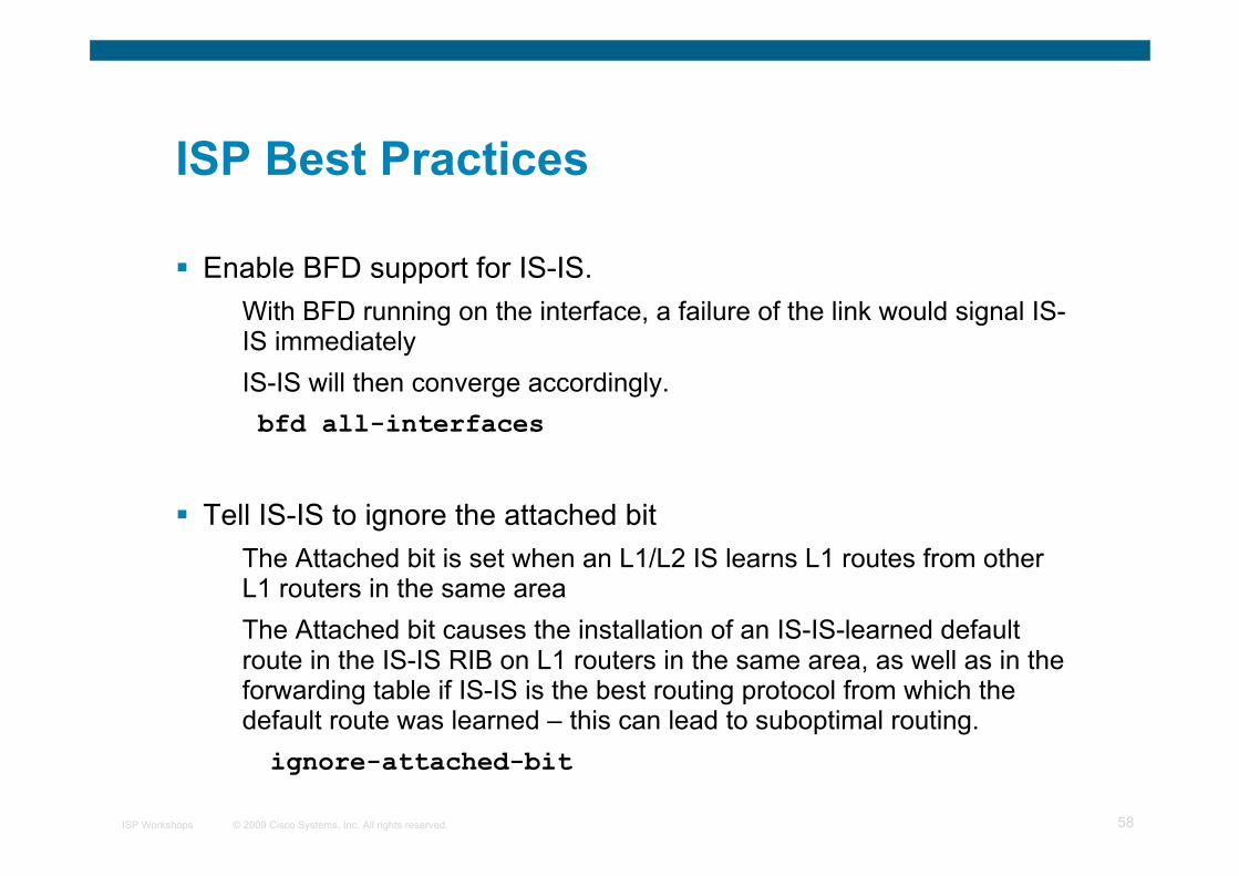
ISP Best Practices
Enable BFD support for IS-IS.With BFD running on the interface, a failure of the link would signal IS-IS immediatelyIS-IS will then converge accordingly. bfd all-interfaces
Tell IS-IS to ignore the attached bitThe Attached bit is set when an L1/L2 IS learns L1 routes from otherL1 routers in the same areaThe Attached bit causes the installation of an IS-IS-learned defaultroute in the IS-IS RIB on L1 routers in the same area, as well as in theforwarding table if IS-IS is the best routing protocol from which thedefault route was learned – this can lead to suboptimal routing.ignore-attached-bit

© 2009 Cisco Systems, Inc. All rights reserved.ISP Workshops 59
ISP Best Practices
Wait until iBGP is running before providing transit pathset-overload-bit on-startup wait-for-bgp
Avoids blackholing traffic on router restartCauses ISIS to announce its prefixes with highest possiblemetric until iBGP is up and runningWhen iBGP is running, ISIS metrics return to normal, make thepath valid
Enable the IPv6 address family for in IS-IS. address-family ipv6
Enable multi-topology support for IPv6 in IS-IS.Multi-topology support allows the IPv4 topology to beindependent of that of IPv6 multi-topology

© 2009 Cisco Systems, Inc. All rights reserved.ISP Workshops 60
ISP Best Practices
Things to consider on routers operating as Level-1-onlyIS's:
IS-IS BCP techniques under the IS-IS routing processIn addition to the interface, tell the IS-IS routing process tooperate in a Level-1 area only
router isis 1
is-type level-1

© 2009 Cisco Systems, Inc. All rights reserved.ISP Workshops 61
ISP Best Practices
Things to consider on routers operating as Level-1 and Level-2 IS’s:To prevent sub-optimal routing of traffic from L1 IS's in one area to L1 IS's inanother area, configure and enable Route Leaking on L1/L2 routers thatform the backbone connectivity between two or more different areasRoute Leaking permits L1/L2 routers to install L1 routes learned from onearea into L1 IS’s routing/forwarding tables in another areaThis allows for reachability between L1 routers located behind L1/L2 routersin different areas
router isis 1 redistribute isis ip level-2 into level-1 route-map FOO!ip prefix-list foo permit 0.0.0.0/0 le 32!route-map FOO permit 10 match ip address prefix-list foo

© 2009 Cisco Systems, Inc. All rights reserved.ISP Workshops 62
ISP Best Practices
SummaryBest practice recommendations are commonly implemented onmany ISP backbonesEnsures efficient and scalable operation of ISIS

© 2009 Cisco Systems, Inc. All rights reserved.ISP Workshops 63
Introduction to ISIS
ISP/IXP Workshops