introduction to internet of things prof. sudip misra ... · you can connect for four different...
TRANSCRIPT

Introduction to Internet of ThingsProf. Sudip Misra
Department of Computer Science & EngineeringIndian Institute of Technology, Kharagpur
Lecture - 30Implementation of IoT with Raspberry Pi- I
In the previous lectures on introduction to Raspberry pi, we have learned about how to
configure Raspberry pi and how to use it along with 2 bear basic sensors on is killer
sensor and the other one a camera sensor. So, 2 sensors were used and the basic
interfacing was introduced to you in the previous 2 lectures. In this lecture you are going
to learn about how to integrate Raspberry pi for enabling IoT development.
So, here you are going to learn about you know these things in more detail. So, not only
this lecture but the next 3 lecture I mean this one and the next 2 lectures you are going to
learn about how to integrate the sensors, how to integrate the sensors different types of
sensors not just one or two, but different types of sensors at the same time then after
these sensors have collected this data then how to send the data how to disseminate the
data through some kind of creation of socket to a remote server for that processing using
in the UDP protocol which is a transport layer protocols. So, using UDP how to do
particular this particular thing you are going to learn and there after you are also going to
learn in this and the next 2 lectures about you know about how to visualize the data at the
server.
So, the data is received then we have to visualize the data is received at the server at the
server how to visualize the data this is what we are going to learn. So, I and Mr.
Anandroop Mukharji; your TA is going to taking through these few steps for achieving
these things; that means, the data acquisition through these different types of sensors then
sending through the network and there after you know visualizing the data at the server.
Hello, in this lecture this lecture will be covering 3 different parts of implementation of
IoT with Raspberry pi. So, in part one will be discussing about using Raspberry pi to
capture data from sensors and making a basic decision on the basis of capture data to
actuate some device.

(Refer Slide Time: 02:55)
So, first of all 2 recapitulate internet of things basically needs to create an interactive
environment and additionally it has a network of devices which are connected together.
So, bringing these 2 together for this particular topic will get into the hands on.
(Refer Slide Time: 03:16)
So, another thing regarding sensors as of already learnt by now and it has been discussed
many times sensors are electronic elements which convert physical quantity into
electrical signals or any measurable quantity into electrical signals and sensors can be
primarily analog or digital.

(Refer Slide Time: 03:37)
Similarly Actuators; Actuators are electro mechanical devices or they can be standalone
mechanical devices also and generally they actuate or convert energy into motion. So,
mainly they are used for providing control motion to other components in a big system.
(Refer Slide Time: 03:59)
So, in this a system overview is as follows sensor and actuator are interfaced with
Raspberry pi, data is read from the sensor the actuator is controlled according to the
reading from the sensor and the actuator basically which is connected to the sensor is
being controlled from the readings and this control mechanism will be showing a brief

decision making loop which can be replaced by additional much higher inversion like
machine learning statistical learning or even de-planning best method.
(Refer Slide Time: 04:42)
So, for this, the following are the system requirements we are again using a DHT sensor
which as a digital humidity and temperature sensor we are using a 4.7 kilo ohm resister
relay some jumper wires Raspberry pi and mini fan which we have going to connect to
the relay to show the effectiveness of our decision making approach.
(Refer Slide Time: 05:05)

So, as you already know this digital humidity and temperature sensor it has got 4 pins.
So, generally when you keep it like it is shown in the slide from left to right you number
the pins 1 up to 4 and pin,one is generally use for power supply rangers from 3.3 to 5
volt pin 2 supplies the data to the process a board to which this sensor is connected, pin 3
is generally kept open and pin 4 is connected to the ground.
(Refer Slide Time: 05:39)
And this one is called the relay board it is an electromechanical switch. So, it has got 3
output terminals starting from left to right. So, in this particular board you can see there
are actually four relays this is a composite board consisting of four different relays. So,
you can connect for four different devices to it this single entity is known as one relay
and in electronic we call this a sugar cube relay generally you can find sugar cube relays
ranging from operating voltage as of 6 volts up to 12 volts.
So, as you can see there are 3 terminals corresponding to each relay. So, from left to right
the first terminal is designation no or normally open the middle one is common and the
third terminal is known as NC are normally close.
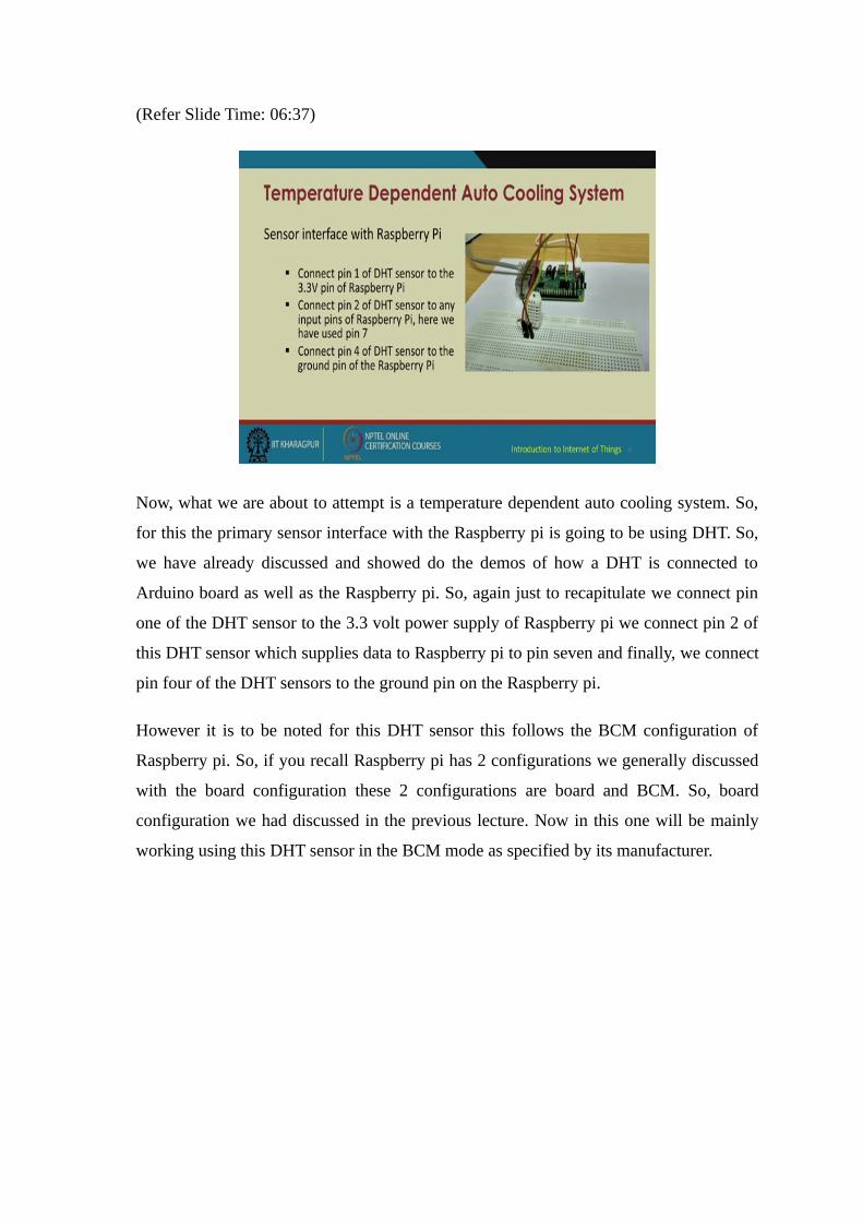
(Refer Slide Time: 06:37)
Now, what we are about to attempt is a temperature dependent auto cooling system. So,
for this the primary sensor interface with the Raspberry pi is going to be using DHT. So,
we have already discussed and showed do the demos of how a DHT is connected to
Arduino board as well as the Raspberry pi. So, again just to recapitulate we connect pin
one of the DHT sensor to the 3.3 volt power supply of Raspberry pi we connect pin 2 of
this DHT sensor which supplies data to Raspberry pi to pin seven and finally, we connect
pin four of the DHT sensors to the ground pin on the Raspberry pi.
However it is to be noted for this DHT sensor this follows the BCM configuration of
Raspberry pi. So, if you recall Raspberry pi has 2 configurations we generally discussed
with the board configuration these 2 configurations are board and BCM. So, board
configuration we had discussed in the previous lecture. Now in this one will be mainly
working using this DHT sensor in the BCM mode as specified by its manufacturer.
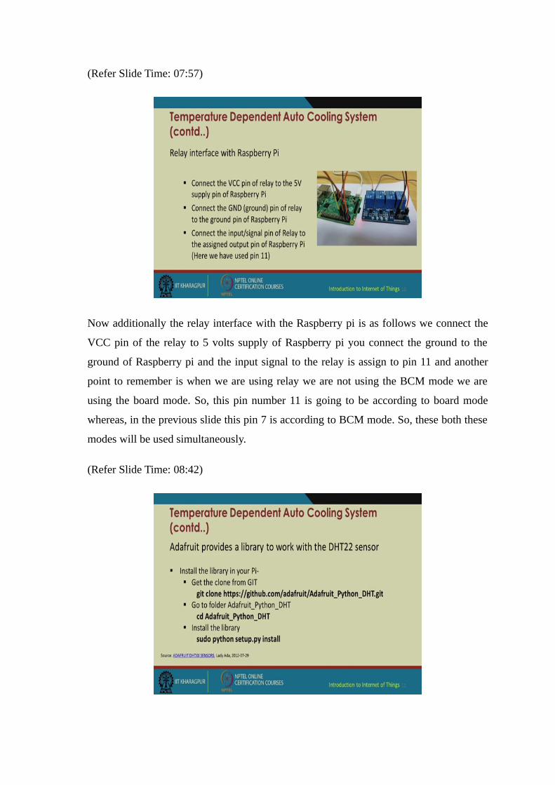
(Refer Slide Time: 07:57)
Now additionally the relay interface with the Raspberry pi is as follows we connect the
VCC pin of the relay to 5 volts supply of Raspberry pi you connect the ground to the
ground of Raspberry pi and the input signal to the relay is assign to pin 11 and another
point to remember is when we are using relay we are not using the BCM mode we are
using the board mode. So, this pin number 11 is going to be according to board mode
whereas, in the previous slide this pin 7 is according to BCM mode. So, these both these
modes will be used simultaneously.
(Refer Slide Time: 08:42)

Now, try to beginning the program in part like in Arduino we install and additional
library for this DHT sensor. Similarly for Raspberry pi we need to install in additional
library from Adafruit which basically supplied this sensor. So, we are using this DHT 22
sensor first of all in your Raspberry pi you need to install your Adafruit DHT sensor
library using the following command and a point to remember is since you your using
python base scripting we are going to implement the DHT python library you may be
able to find come or cross DHT C library, DHT C++ libraries that we have more
interested on in the python library.
So, the first line is this git clone https you follow this link and you press enter you will
see here Raspberry pi it terminal its starts if it is connected to the internet it will start
download in this folder if go to the once the download is finished we go to the download
at folder by putting in this command cd Adafruit underscore python underscore DHT
because this will be the name of the folder which has been downloaded on your
Raspberry pi system and remember this is not the installation the installation is get to
come. So, after you go into the directory you install the library by running this command
sudo python setup dot py install. So, once your installation is successful you can easily
start creating codes for DHT using python and Raspberry pi.
(Refer Slide Time: 10:32)
So, we have a sample DHT enterprising program with Raspberry pi first line starts off
with importing the GPIO pins. So, import RPi dot GPIO as GPIO then we import the
time library for calling in the sleep function which provides delays 2 hour program and
then we import the Adafruit underscore DHT library which we previously installed now
the GPIO mode is initially set as board and warning have been set to false for the
Adafruit it automatically takes the board mode as BCM. So, we are not explicitly
identifying anything. So, sensor equal to Adafruit underscore DHT dot AM 2 3 2; 2 3 0
2. So, this line as to be explicitly mentioned according to the documentation provided by
the manufacturer and then we just printer line to signify whether this sensor have been
successfully initialized or not and we assigned humidity and temperature values from the
Adafruit library function by using read underscore retry and in name this sensor which
we initially called and which is connected to BCM pin 4.
In the next line we print the temperature and humidity values iteratively not a iteratively
we print this once, but we format it according to our needs.
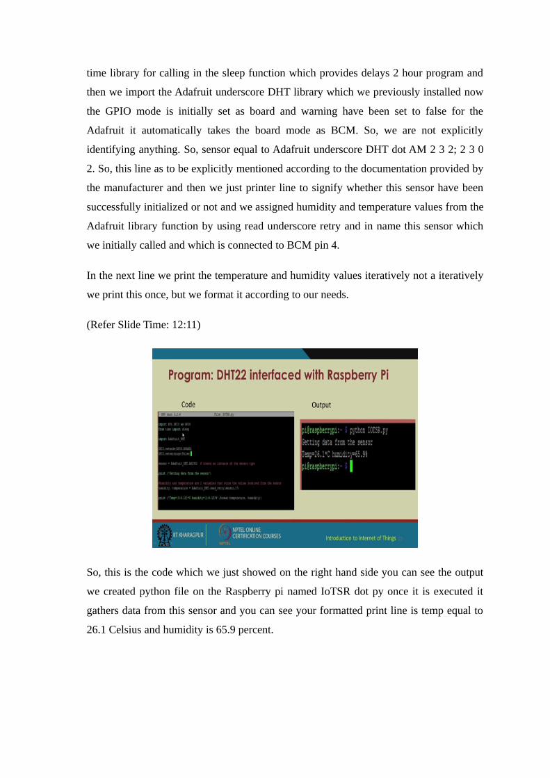
(Refer Slide Time: 12:11)
So, this is the code which we just showed on the right hand side you can see the output
we created python file on the Raspberry pi named IoTSR dot py once it is executed it
gathers data from this sensor and you can see your formatted print line is temp equal to
26.1 Celsius and humidity is 65.9 percent.

(Refer Slide Time: 12:52)
So, we can zoom into the hardware circuitry now as you can see this is your DHT sensor
it is placed on the breadboard and according to the configuration mentioned previously in
this slide we have connected the VCC ground and the data pin to the appropriate pins on
the Raspberry pi board there are additional component attached will come to those later.
But for now will be focusing on only these 3 wires the brown wire the red wire and the
black wire.
(Refer Slide Time: 13:35)

So, coming back to the programming part I have remotely logged into the Raspberry pi
system just increase the font little bit. So, using this terminal I have actually logged into
the Raspberry pi. As you can see over here pi at the rate Raspberry pi I go into the
directory I see that I have testing file named DHT temp dot py lecture on this first.
(Refer Slide Time: 14:41)
So, we give the simple command python DHT temp dot py as soon as it is executed is a
simple code to fetch only the temperature readings from the DHT sensor, so, the
temperature reading as been read as 25.0 degree Celsius.
Now, will look at the IoTSR file, so, we have our IoTSR file over here lets open and
editor and check whether the contents are the same.

(Refer Slide Time: 15:33)
So, we have imported the GPIO library we have imported the time module we have
imported the Adafruit library we installed we said the board mode. So, as have told you
before the Adafruit dot read retry this thing is pin is on by defaults setting BCM mode.
So, this pin number four is according to BCM mode whereas, have connected a relay I
will come to that in the consecutive slides have connected a relay and it is connected to
pin eleven according to the board mode.
Before going furthers, we have not checked our Raspberry pi is working fine the DHT
sensor is working fine.
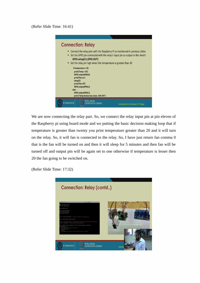
(Refer Slide Time: 16:41)
We are now connecting the relay part. So, we connect the relay input pin at pin eleven of
the Raspberry pi using board mode and we putting the basic decision making loop that if
temperature is greater than twenty you print temperature greater than 20 and it will turn
on the relay. So, it will fan is connected to the relay. So, I have just return fan comma 0
that is the fan will be turned on and then it will sleep for 5 minutes and then fan will be
turned off and output pin will be again set to one otherwise if temperature is lesser then
20 the fan going to be switched on.
(Refer Slide Time: 17:32)

So, on the left hand side this is the code actually open this code few movements back on
the Raspberry pi console and on the right hand side you have this relay board you have
this DHT sensor connected to the Raspberry pi.
(Refer Slide Time: 17:52)
Now this connection of the Li-po with the fan sorry, the connection of the relay with the
fan is as follows we are connecting we are using lithium polymer battery we can use any
other battery of sufficient rating since the fan we are using runs on 12 volt we are using a
12 volt Li-po battery to operate the fan the normally open terminal of the relay or the
positive terminal is connected to the positive terminal of the fan in the common terminal
of the relay is connected to positive terminal of battery negative terminal of battery is
connected to negative terminal of the fan and when these connections have been made
and the connection have been rechecked we run the IoTSR dot py file. So, the connection
will looks something like this.

(Refer Slide Time: 18:46)
(Refer Slide Time: 18:58)
Now let us again log into Raspberry pi. So, once we execute this file you will see the
output that prior to that I like to show you this is my Raspberry pi this was my DHT
sensor giving me humidity and temperature readings this is my relay board this is the
four channel relay board because you can connect four devices simultaneously. So, this
one unit is known as a relay this single unit is called a sugar cube relay as you can see it
as got 3 terminals normally open common and normally close and we have this small fan
over here which is connected to a Li-po battery 3 cell Li-po. So, again back to the
terminal will execute the code now.

So, as soon as the code is executed it gets the reading of temperature is 25.2 degree
Celsius and humidity is almost seventy 6 percent now the decision making loop has
detected that the temperature is greater than twenty. So, it turns on the fan and after that
after 5 seconds the fan is turned off. So, this can be modified the modifying the loop and
instead of using a normal fls loop you can go for fls loop or a normal rule based decision
making we can; obviously, go for various machine running best approaches only
condition been that you need a lot of data historical data to predict the next action.
So, if you again focus on the circuit I like to show when I run this program again if you
pay attention to the fan and it is connected to this relay board as soon as the program is
executed and if the relay is turned on there will be a light blinking against the
corresponding relay to which the fan is connected to this relay.
So, you see it as detector the temperature greater than 25 the relay as been turned on you
see the fan is now also turned on after 5 second it will turn off. So, basic application is
you can use this for automated cooling systems may be for your pc or may be for your
various other systems or may be in industrial systems. Also suppose if the temperature of
a Furness gets higher or if a temperature of a particular room or work place gets higher
your fan automatically turns on and the network connected device remotely intimates
you that your temperature is going high so, the fan as been turned on.
(Refer Slide Time: 22:22)

So, the outputs have been explode I hope this gave you a bit of learning experience well
cover other things and details in our next slide.
Thank you.