introduction to integrated 1d-2d riverine and urban flood ... · introduction to integrated 1d-2d...
TRANSCRIPT

By Patrick Delaney, DHI
Introduction to Integrated 1D-2D Riverine and Urban Flood Modelling using MIKE FLOOD
© DHI
22nd Latornell Conservation Symposium Weathering Change: Navitating a New Climate
Presentation Outline
© DHI
• About DHI• 1D riverine modeling• 1D collection system modelling• 2D overland flow modelling• 1D-2D coupling of models• Examples

• DHI is an independent, self-governing research and consultancy organisation (non-profit)
• DHI builds competence and promotes technological development relevant to the water and the environment
• DHI has ongoing activities world-wide
• DHI has a total staff of over 1100
What is DHI?
• Coupled 1D and 2D urban and riverine flood modelling
• Integrated watershed hydrology modelling
• Stormwater drainage and collection system modelling
• Wastewater and combined sewer hydraulic modelling
• Flood and lake forecasting system development
DHI Consulting Services
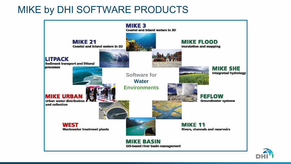
MIKE by DHI SOFTWARE PRODUCTS
Software for Water
Environments

What is MIKE FLOOD
© DHI
What is MIKE FLOOD?
© DHI
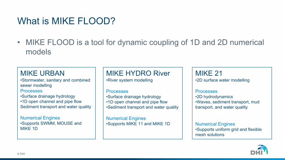
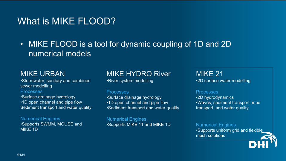
• MIKE FLOOD is a tool for dynamic coupling of 1D and 2D numericalmodels
MIKE URBAN•Stormwater, sanitary and combined sewer modellingProcesses•Surface drainage hydrology•1D open channel and pipe flow Sediment transport and water quality
Numerical Engines•Supports SWMM, MOUSE and MIKE 1D
MIKE HYDRO River•River system modelling
Processes•Surface drainage hydrology•1D open channel and pipe flow•Sediment transport and water quality
Numerical Engines•Supports MIKE 11 and MIKE 1D
MIKE 21•2D surface water modelling
Processes•2D hydrodynamics •Waves, sediment transport, mud transport, and water quality
Numerical Engines•Supports uniform grid and flexible mesh solutions
© DHI
What is MIKE FLOOD?
• MIKE FLOOD is a tool for dynamic coupling of 1D and 2D numerical models
MIKE URBAN•Stormwater, sanitary and combined sewer modellingProcesses•Surface drainage hydrology•1D open channel and pipe flow Sediment transport and water quality
Numerical Engines•Supports SWMM, MOUSE and MIKE 1D
MIKE HYDRO River•River system modelling
Processes•Surface drainage hydrology•1D open channel and pipe flow•Sediment transport and water quality
Numerical Engines•Supports MIKE 11 and MIKE 1D
MIKE 21•2D surface water modelling
Processes•2D hydrodynamics •Waves, sediment transport, mud transport, and water quality
Numerical Engines•Supports uniform grid and flexible mesh solutions
© DHI
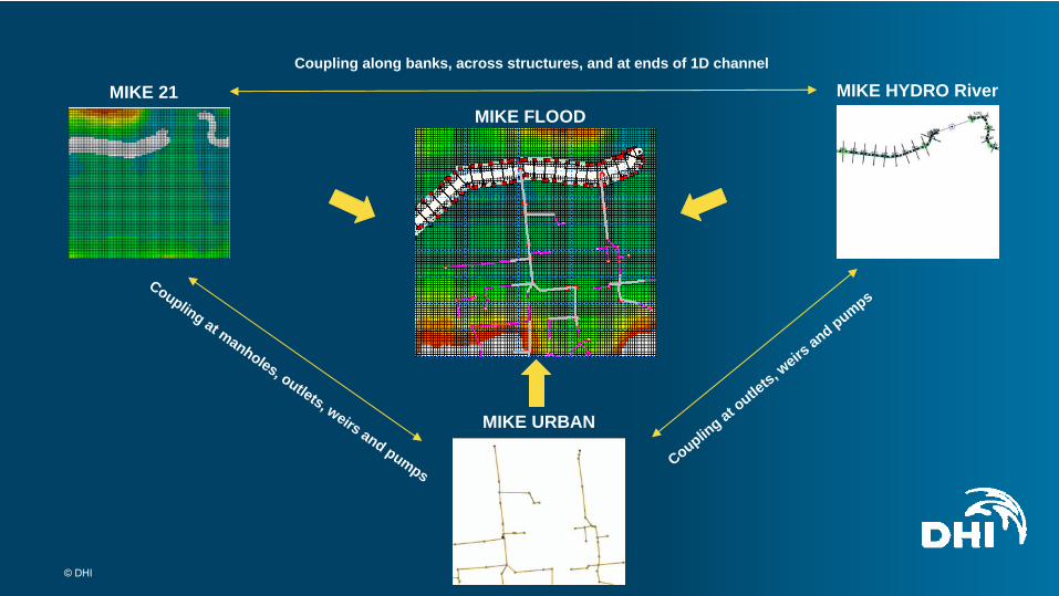
MIKE FLOODMIKE 21 MIKE HYDRO River
MIKE URBAN
Coupling along banks, across structures, and at ends of 1D channel
Coupling at manholes, outlets, weirs and pumpsCouplin
g at outle
ts, weirs
and pumps
© DHI
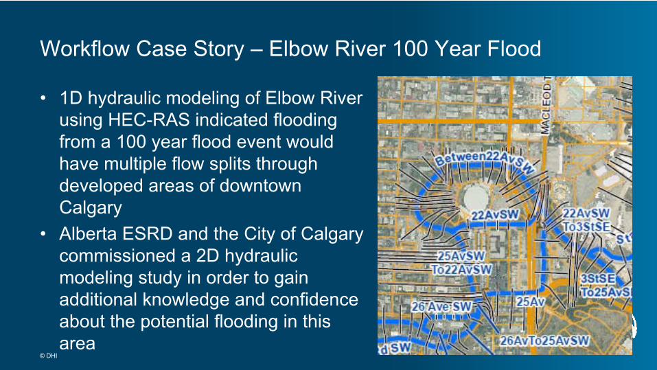
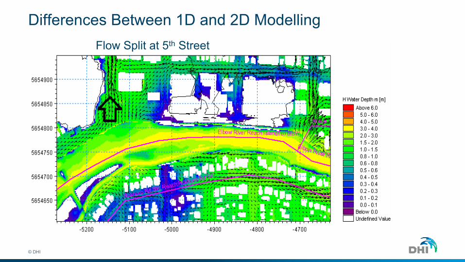
• 1D hydraulic modeling of Elbow River using HEC-RAS indicated flooding from a 100 year flood event would have multiple flow splits through developed areas of downtown Calgary
• Alberta ESRD and the City of Calgary commissioned a 2D hydraulic modeling study in order to gain additional knowledge and confidence about the potential flooding in this area
Workflow Case Story – Elbow River 100 Year Flood
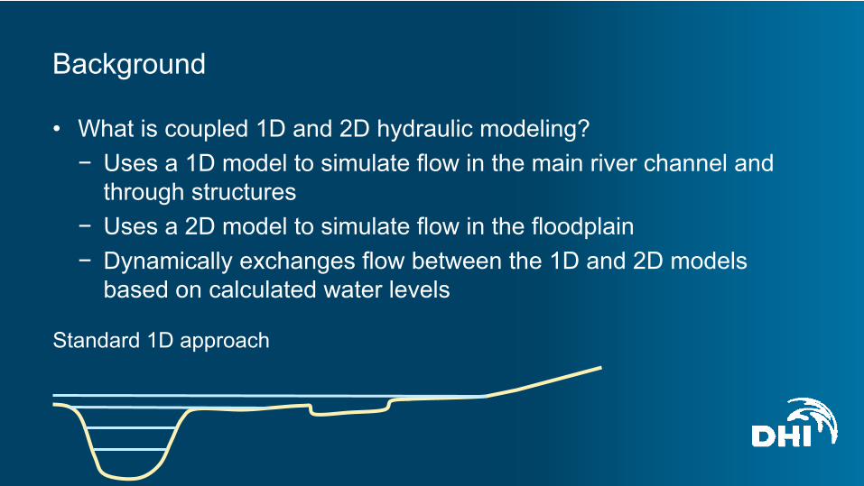
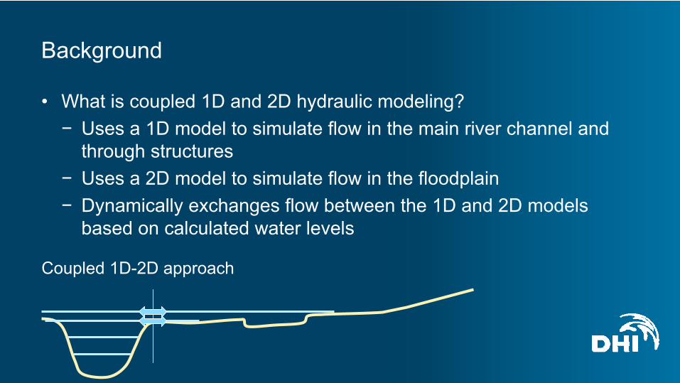
• What is coupled 1D and 2D hydraulic modeling?− Uses a 1D model to simulate flow in the main river channel and
through structures− Uses a 2D model to simulate flow in the floodplain− Dynamically exchanges flow between the 1D and 2D models
based on calculated water levels
Background
Standard 1D approach
• What is coupled 1D and 2D hydraulic modeling?− Uses a 1D model to simulate flow in the main river channel and
through structures− Uses a 2D model to simulate flow in the floodplain− Dynamically exchanges flow between the 1D and 2D models
based on calculated water levels
Background
Coupled 1D-2D approach
© DHI
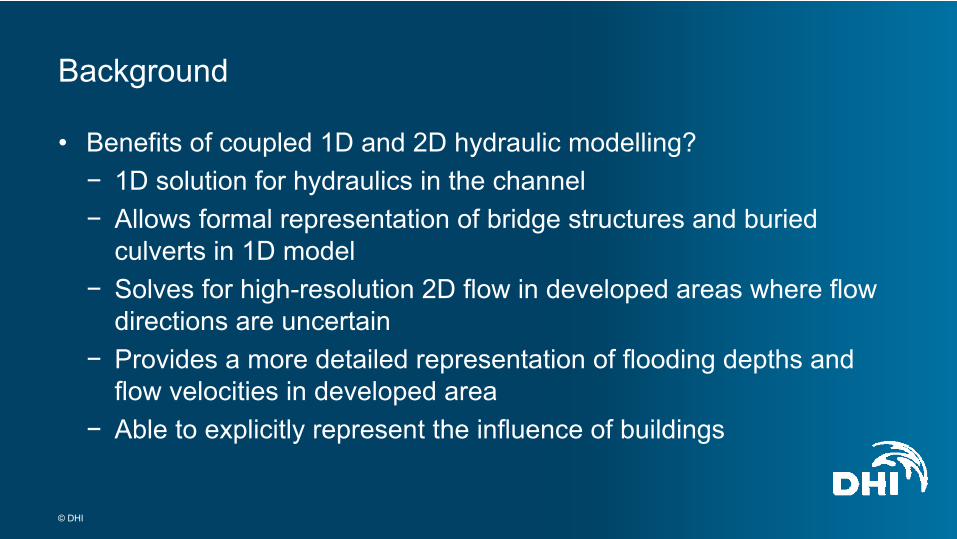
• Benefits of coupled 1D and 2D hydraulic modelling?− 1D solution for hydraulics in the channel − Allows formal representation of bridge structures and buried
culverts in 1D model− Solves for high-resolution 2D flow in developed areas where flow
directions are uncertain− Provides a more detailed representation of flooding depths and
flow velocities in developed area− Able to explicitly represent the influence of buildings
Background
© DHI
• Convert existing 1D river model from HEC-RAS to MIKE 11• Trim the 1D river model to represent only the 1D channel flow• Prepare a 2D MIKE 21 model• Construct the MIKE FLOOD model by coupling the 1D MIKE 11
model to the 2D MIKE 21 model• Calibrate the MIKE FLOOD model• Run design flood events and map results
Project Scope of Work
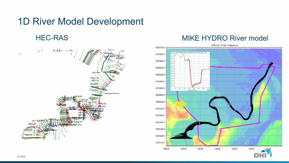
1D River Model Development
© DHI
HEC-RAS MIKE HYDRO River model
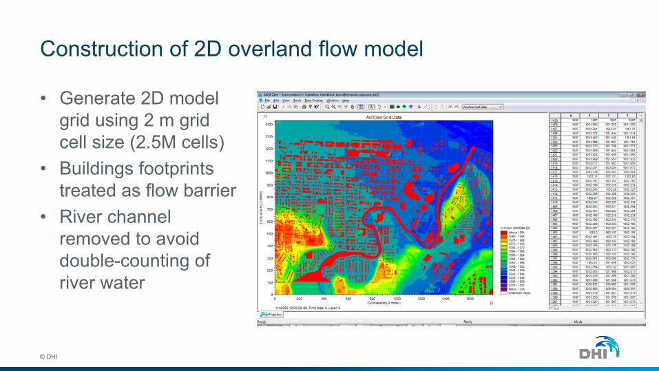
Construction of 2D overland flow model
© DHI
• Generate 2D model grid using 2 m grid cell size (2.5M cells)
• Buildings footprints treated as flow barrier
• River channel removed to avoid double-counting of river water
Construction of MIKE FLOOD Model
© DHI
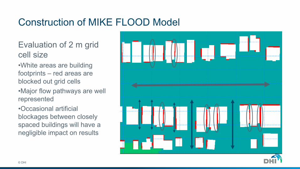
Evaluation of 2 m grid cell size •White areas are building footprints – red areas are blocked out grid cells•Major flow pathways are well represented •Occasional artificial blockages between closely spaced buildings will have a negligible impact on results
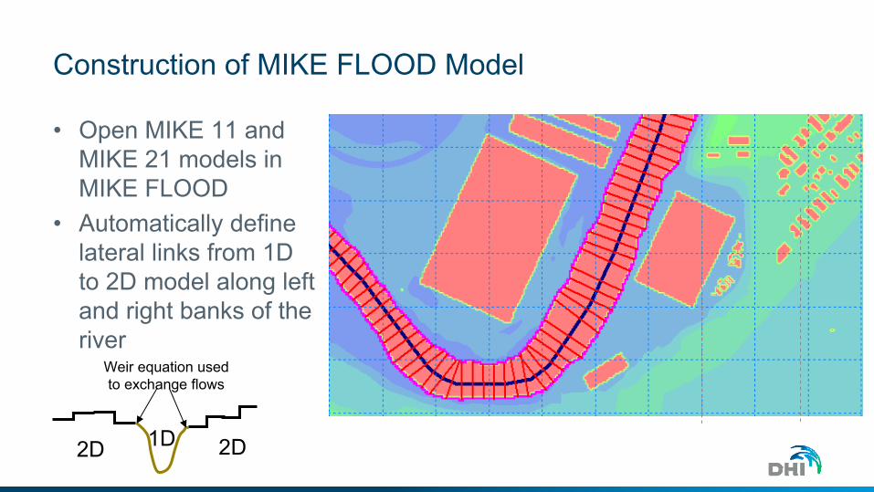
Construction of MIKE FLOOD Model
• Open MIKE 11 and MIKE 21 models in MIKE FLOOD
• Automatically define lateral links from 1D to 2D model along left and right banks of the river
Weir equation used to exchange flows
2D 2D1D
© DHI
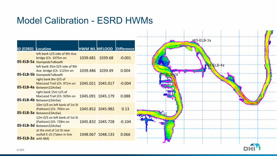
Model Calibration - ESRD HWMs
© DHI
ID (ESRD) Location HWM WL MFLOOD Difference
05‐ELB‐5a
left bank U/S side of 9th Ave. bridge (Ch. 1075m on StampedeToBowRi
1039.681 1039.68 ‐0.001
05‐ELB‐5b
left bank 35m D/S side of 9th Ave. bridge (Ch. 1125m on StampedeToBowRi
1039.486 1039.49 0.004
05‐ELB‐4a
right bank 8m D/S of MacLeod Trail (Ch. 971m on Between22AvSw)
1045.021 1045.017 ‐0.004
05‐ELB‐4b
right bank 15m U/S of MacLeod Trail (Ch. 929m on Between22AvSw)
1045.091 1045.179 0.088
05‐ELB‐3a
10m U/S on left bank of 1st St (Pattison) (Ch. 705m on Between22AvSw)
1045.852 1045.982 0.13
05‐ELB‐3d
12m D/S on left bank of 1st St (Pattison) (Ch. 728m on Between22AvSw)
1045.832 1045.728 ‐0.104
05‐ELB‐2a
at the end of 1st St near outfall E‐25 (Taken in line with BM)
1048.067 1048.133 0.066

04.
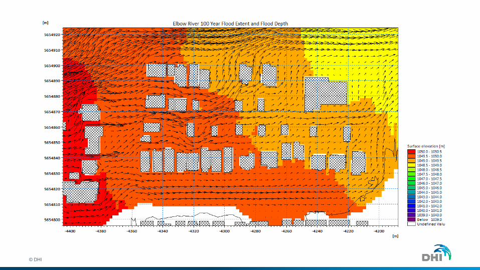
Modeling the 100 Year Flood Event
© DHI
© DHI
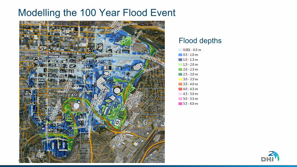
Modelling the 100 Year Flood Event
Flood depths
© DHI
Differences Between 1D and 2D ModellingFlow Split at 5th Street
© DHI
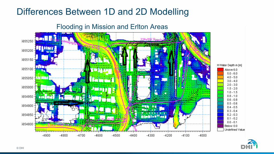
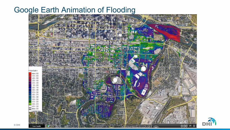
Differences Between 1D and 2D ModellingFlooding in Mission and Erlton Areas
© DHI
Google Earth Animation of Flooding
© DHI
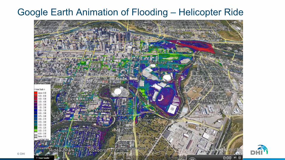
Google Earth Animation of Flooding – Helicopter Ride
1D-2D Urban Flood Modelling
© DHI
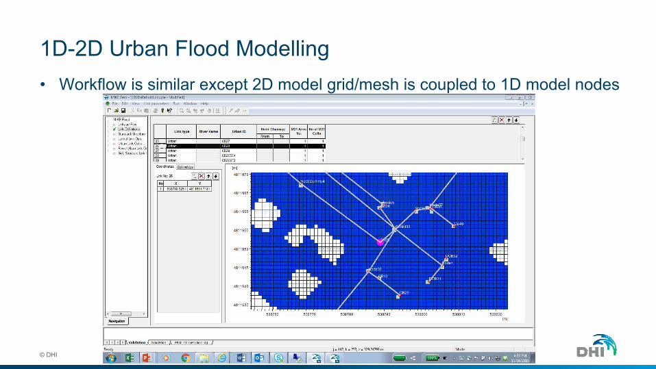
• Workflow is similar except 2D model grid/mesh is coupled to 1D model nodes
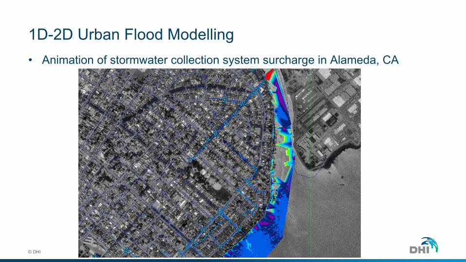
1D-2D Urban Flood Modelling
© DHI
• Animation of stormwater collection system surcharge in Alameda, CA
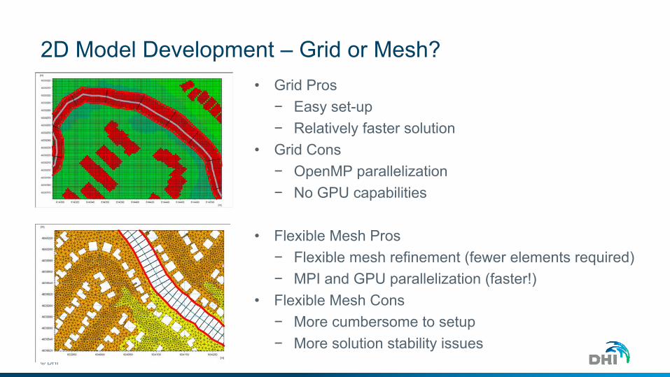
2D Model Development – Grid or Mesh?
© DHI
• Grid Pros− Easy set-up− Relatively faster solution
• Grid Cons− OpenMP parallelization− No GPU capabilities
• Flexible Mesh Pros− Flexible mesh refinement (fewer elements required)− MPI and GPU parallelization (faster!)
• Flexible Mesh Cons− More cumbersome to setup− More solution stability issues
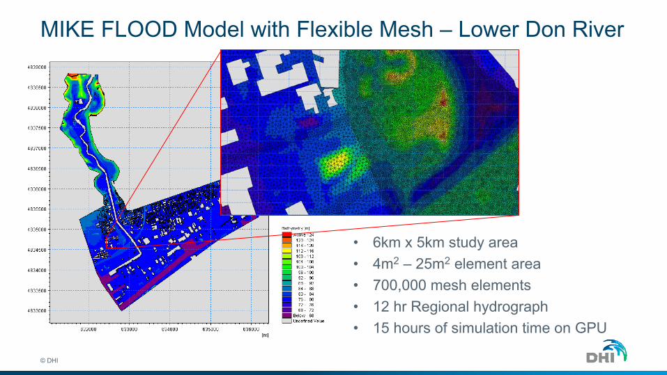
MIKE FLOOD Model with Flexible Mesh – Lower Don River
© DHI
• 6km x 5km study area• 4m2 – 25m2 element area• 700,000 mesh elements• 12 hr Regional hydrograph • 15 hours of simulation time on GPU

MIKE FLOOD Model with Flexible Mesh – Lower Don River
© DHI

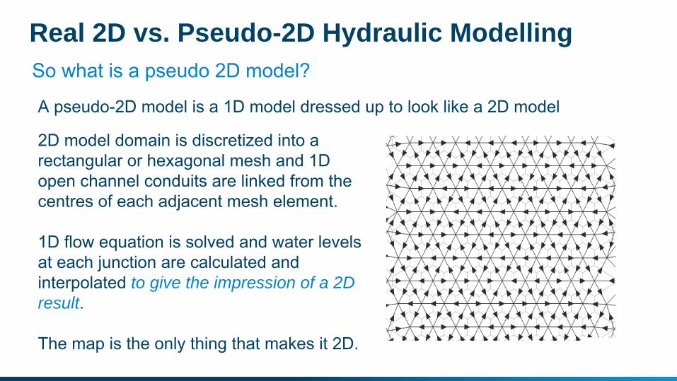
So what is a pseudo 2D model?
Real 2D vs. Pseudo-2D Hydraulic Modelling
A pseudo-2D model is a 1D model dressed up to look like a 2D model
2D model domain is discretized into a rectangular or hexagonal mesh and 1D open channel conduits are linked from the centres of each adjacent mesh element.
1D flow equation is solved and water levels at each junction are calculated and interpolated to give the impression of a 2D result.
The map is the only thing that makes it 2D.
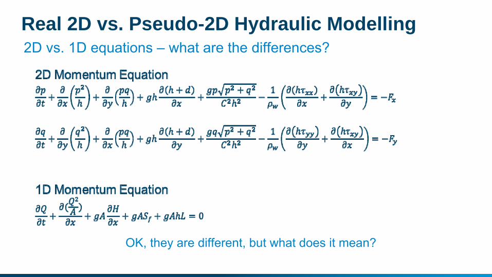
2D vs. 1D equations – what are the differences?Real 2D vs. Pseudo-2D Hydraulic Modelling
OK, they are different, but what does it mean?
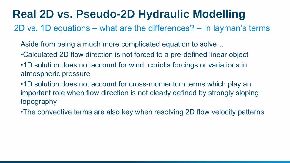
2D vs. 1D equations – what are the differences? – In layman’s termsReal 2D vs. Pseudo-2D Hydraulic Modelling
Aside from being a much more complicated equation to solve….•Calculated 2D flow direction is not forced to a pre-defined linear object•1D solution does not account for wind, coriolis forcings or variations in atmospheric pressure•1D solution does not account for cross-momentum terms which play an important role when flow direction is not clearly defined by strongly sloping topography•The convective terms are also key when resolving 2D flow velocity patterns
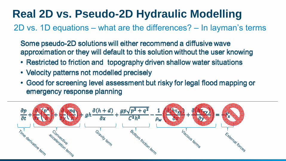
2D vs. 1D equations – what are the differences? – In layman’s termsReal 2D vs. Pseudo-2D Hydraulic Modelling
Convective
acceleration terms
Gravity term
Bottom friction term
Viscous terms
Time derivative term
External forces
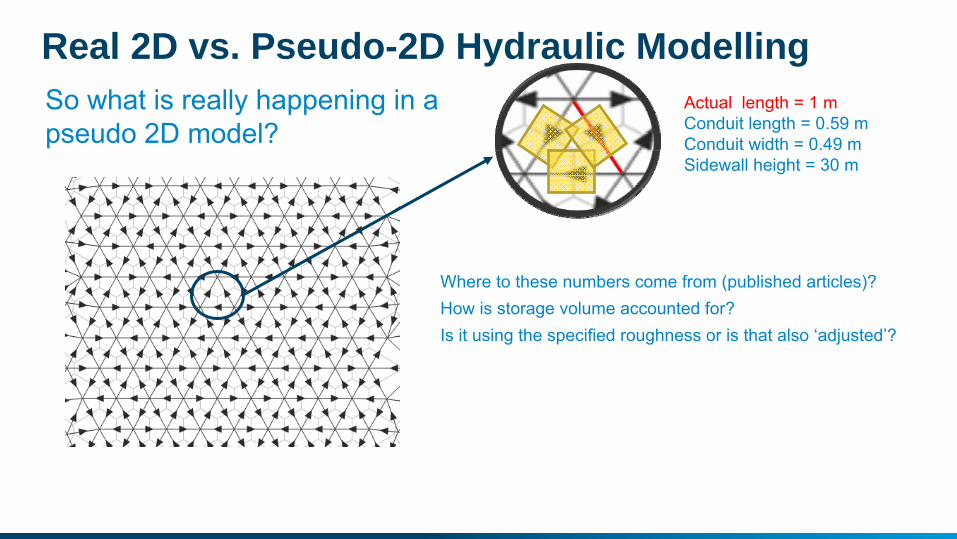
Actual length = 1 mConduit length = 0.59 mConduit width = 0.49 mSidewall height = 30 m
Where to these numbers come from (published articles)?How is storage volume accounted for?Is it using the specified roughness or is that also ‘adjusted’?
So what is really happening in a pseudo 2D model?
Real 2D vs. Pseudo-2D Hydraulic Modelling