introduction to directx raytracing -...
TRANSCRIPT
21© NVIDIA 2019 E. Haines, T. Akenine-Möller (eds.), Ray Tracing Gems, https://doi.org/10.1007/978-1-4842-4427-2_3
CHAPTER 3
Introduction to DirectX RaytracingChris Wyman and Adam Marrs NVIDIA
ABSTRACT
Modern graphics APIs such as DirectX 12 expose low-level hardware access and control to developers, often resulting in complex and verbose code that can be intimidating for novices. In this chapter, we hope to demystify the steps to set up and use DirectX for ray tracing.
3.1 INTRODUCTION
At the 2018 Game Developers Conference, Microsoft announced the DirectX Raytracing (DXR) API, which extends DirectX 12 with native support for ray tracing. Beginning with the October 2018 update to Windows 10, the API runs on all DirectX 12 GPUs, either using dedicated hardware acceleration or via a compute-based software fallback. This functionality enables new options for DirectX renderers, ranging from full-blown, film- quality path tracers to more humble ray-raster hybrids, e.g., replacing raster shadows or reflections with ray tracing.
As with all graphics APIs, a few prerequisites are important before diving into code. This chapter assumes a knowledge of ray tracing fundamentals, and we refer readers to other chapters in this book, or introductory texts [4, 10], for the basics. Additionally, we assume familiarity with GPU programming; to understand ray tracing shaders, experience with basic DirectX, Vulkan, or OpenGL helps. For lower-level details, prior experience with DirectX 12 may be beneficial.
3.2 OVERVIEW
GPU programming has three key components, independent of the API: (1) the GPU device code, (2) the CPU host-side setup process, and (3) the sharing of data between host and device. Before we discuss each of these components, Section 3.3 walks through important software and hardware requirements to get started building and running DXR-based programs.
We then talk about each core component, starting with how to code DXR shaders in Sections 3.4, 3.5, and 3.6. The high-level shading language (HLSL) code for DXR looks similar to a serial CPU ray tracer written in C++. Using libraries to abstract
22
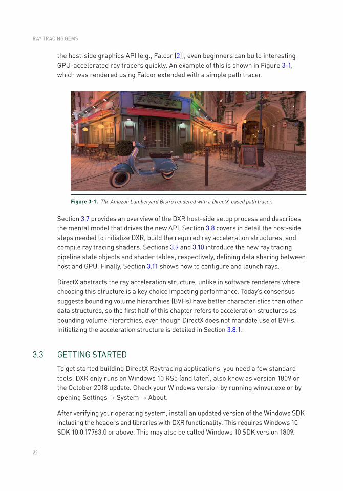
the host-side graphics API (e.g., Falcor [2]), even beginners can build interesting GPU-accelerated ray tracers quickly. An example of this is shown in Figure 3-1, which was rendered using Falcor extended with a simple path tracer.
Figure 3-1. The Amazon Lumberyard Bistro rendered with a DirectX-based path tracer.
Section 3.7 provides an overview of the DXR host-side setup process and describes the mental model that drives the new API. Section 3.8 covers in detail the host-side steps needed to initialize DXR, build the required ray acceleration structures, and compile ray tracing shaders. Sections 3.9 and 3.10 introduce the new ray tracing pipeline state objects and shader tables, respectively, defining data sharing between host and GPU. Finally, Section 3.11 shows how to configure and launch rays.
DirectX abstracts the ray acceleration structure, unlike in software renderers where choosing this structure is a key choice impacting performance. Today’s consensus suggests bounding volume hierarchies (BVHs) have better characteristics than other data structures, so the first half of this chapter refers to acceleration structures as bounding volume hierarchies, even though DirectX does not mandate use of BVHs. Initializing the acceleration structure is detailed in Section 3.8.1.
3.3 GETTING STARTED
To get started building DirectX Raytracing applications, you need a few standard tools. DXR only runs on Windows 10 RS5 (and later), also know as version 1809 or the October 2018 update. Check your Windows version by running winver.exe or by opening Settings → System → About.
After verifying your operating system, install an updated version of the Windows SDK including the headers and libraries with DXR functionality. This requires Windows 10 SDK 10.0.17763.0 or above. This may also be called Windows 10 SDK version 1809.
RAY TRACING GEMS
23
You need Visual Studio or a similar compiler. Both the professional and free community versions of Visual Studio 2017 work.
Finally, ray tracing requires a GPU that supports DirectX 12 (check by running dxdiag.exe). Having hardware-accelerated ray tracing improves performance dramatically for complex scenes and higher resolutions. Tracing a few rays per pixel may be feasible on older GPUs, especially when using simple scenes or lower resolutions. For various reasons, ray tracing typically requires more memory than rasterization. Hardware with less onboard memory may exhibit terrible performance due to thrashing.
3.4 THE DIRECTX RAYTRACING PIPELINE
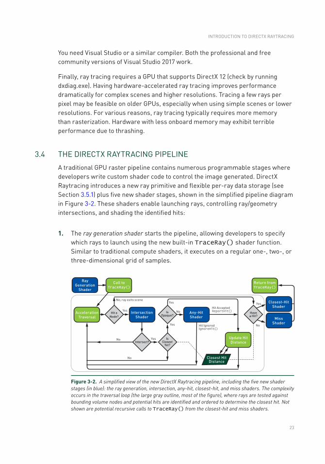
A traditional GPU raster pipeline contains numerous programmable stages where developers write custom shader code to control the image generated. DirectX Raytracing introduces a new ray primitive and flexible per-ray data storage (see Section 3.5.1) plus five new shader stages, shown in the simplified pipeline diagram in Figure 3-2. These shaders enable launching rays, controlling ray/geometry intersections, and shading the identified hits:
1. The ray generation shader starts the pipeline, allowing developers to specify which rays to launch using the new built-in TraceRay() shader function. Similar to traditional compute shaders, it executes on a regular one-, two-, or three-dimensional grid of samples.
Figure 3-2. A simplified view of the new DirectX Raytracing pipeline, including the five new shader stages (in blue): the ray generation, intersection, any-hit, closest-hit, and miss shaders. The complexity occurs in the traversal loop (the large gray outline, most of the figure), where rays are tested against bounding volume nodes and potential hits are identified and ordered to determine the closest hit. Not shown are potential recursive calls to TraceRay() from the closest-hit and miss shaders.
INTRODUCTION TO DIRECTX RAYTRACING
24
2. Intersection shaders define the computations for ray intersections with arbitrary primitives. A high-performance default is provided for ray/triangle intersections.
3. Any-hit shaders1 allow controllably discarding otherwise valid intersections, e.g., ignoring alpha-masked geometry after a texture lookup.
4. A closest-hit shader executes at the single closest intersection along each ray. Usually, this computes the color at the intersection point, similar to a pixel shader in the raster pipeline.
5. A miss shader executes whenever a ray misses all geometry in the scene. This allows, for example, lookups into an environment map or a dynamic skylight model.
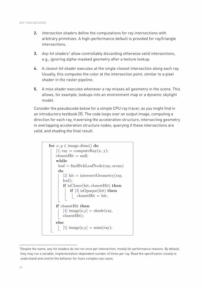
Consider the pseudocode below for a simple CPU ray tracer, as you might find in an introductory textbook [9]. The code loops over an output image, computing a direction for each ray, traversing the acceleration structure, intersecting geometry in overlapping acceleration structure nodes, querying if these intersections are valid, and shading the final result.
1 Despite the name, any-hit shaders do not run once per intersection, mostly for performance reasons. By default, they may run a variable, implementation-dependent number of times per ray. Read the specification closely to understand and control the behavior for more complex use cases.
RAY TRACING GEMS
25
At least for standard use cases, the new DXR shaders have correspondences with parts of this simple ray tracer. The launch size of the ray generation shader corresponds to the image dimensions. Camera computations to generate each pixel’s ray occur in the ray generation shader.
While a ray traverses the bounding volume hierarchy, actual intersections of primitives in the leaf node logically occur in DirectX intersection shaders, and detected intersections can be discarded in the any-hit shader. Finally, once a ray has completed its traversal through the acceleration structure, it is either shaded in the closest-hit shader or given a default color in the miss shader.
3.5 NEW HLSL SUPPORT FOR DIRECTX RAYTRACING
Augmenting the standard HLSL data types, texture and buffer resources, and built- in functions (see the DirectX documentation [5]), Microsoft added various built-in intrinsics to support the functionality needed for ray tracing. New intrinsic functions fall into five categories:
1. Ray traversal functions spawn rays and allow control of their execution.
2. Launch introspection functions query launch dimensions and identify which ray (or pixel) the current thread is processing. These functions are valid in any ray tracing shader.
3. Ray introspection functions query ray parameters and properties and are available whenever you have an input ray (all ray tracing shaders except the ray generation shader).
4. Object introspection functions query object and instance properties and are usable whenever you have an input primitive (intersection, any-hit, and closest-hit shaders).
5. Hit introspection functions query properties of the current intersection. Properties are largely user defined, so these functions allow communication between intersection and hit shaders. These functions are available only during any-hit and closest-hit shaders.
3.5.1 LAUNCHING A NEW RAY IN HLSL
The most important new function, TraceRay(), launches a ray. Logically, this behaves akin to a texture fetch: it pauses your shader for a variable (and potentially large) number of GPU clocks, resuming execution when results are available
INTRODUCTION TO DIRECTX RAYTRACING
26
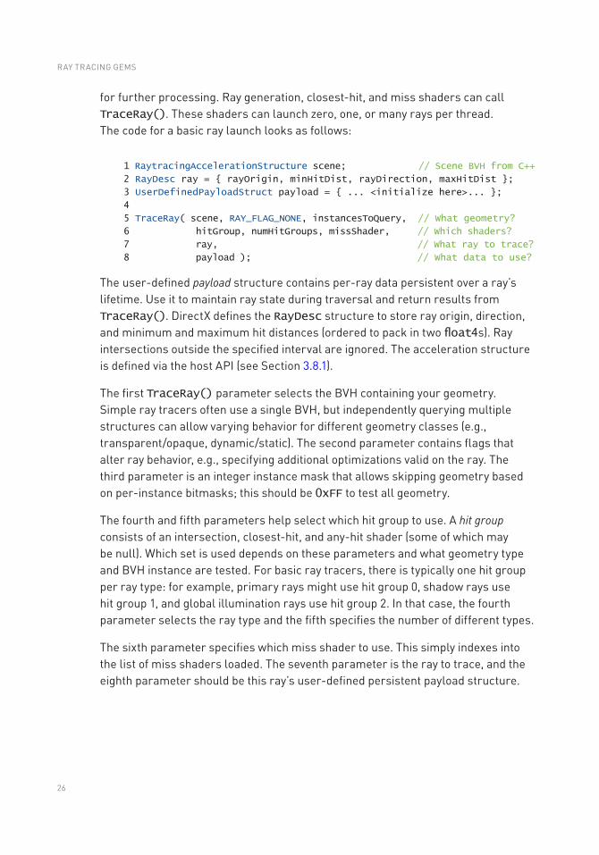
for further processing. Ray generation, closest-hit, and miss shaders can call TraceRay(). These shaders can launch zero, one, or many rays per thread. The code for a basic ray launch looks as follows:
1 RaytracingAccelerationStructure scene; // Scene BVH from C++
2 RayDesc ray = { rayOrigin, minHitDist, rayDirection, maxHitDist };
3 UserDefinedPayloadStruct payload = { ... <initialize here>... };
4
5 TraceRay( scene, RAY_FLAG_NONE, instancesToQuery, // What geometry?
6 hitGroup, numHitGroups, missShader, // Which shaders?
7 ray, // What ray to trace?
8 payload ); // What data to use?
The user-defined payload structure contains per-ray data persistent over a ray’s lifetime. Use it to maintain ray state during traversal and return results from TraceRay(). DirectX defines the RayDesc structure to store ray origin, direction, and minimum and maximum hit distances (ordered to pack in two float4s). Ray intersections outside the specified interval are ignored. The acceleration structure is defined via the host API (see Section 3.8.1).
The first TraceRay() parameter selects the BVH containing your geometry. Simple ray tracers often use a single BVH, but independently querying multiple structures can allow varying behavior for different geometry classes (e.g., transparent/opaque, dynamic/static). The second parameter contains flags that alter ray behavior, e.g., specifying additional optimizations valid on the ray. The third parameter is an integer instance mask that allows skipping geometry based on per-instance bitmasks; this should be 0xFF to test all geometry.
The fourth and fifth parameters help select which hit group to use. A hit group consists of an intersection, closest-hit, and any-hit shader (some of which may be null). Which set is used depends on these parameters and what geometry type and BVH instance are tested. For basic ray tracers, there is typically one hit group per ray type: for example, primary rays might use hit group 0, shadow rays use hit group 1, and global illumination rays use hit group 2. In that case, the fourth parameter selects the ray type and the fifth specifies the number of different types.
The sixth parameter specifies which miss shader to use. This simply indexes into the list of miss shaders loaded. The seventh parameter is the ray to trace, and the eighth parameter should be this ray’s user-defined persistent payload structure.
RAY TRACING GEMS
27
3.5.2 CONTROLLING RAY TRAVERSAL IN HLSL
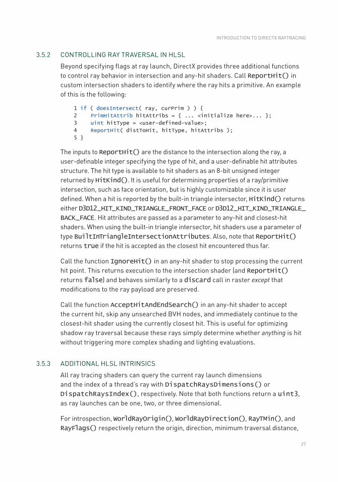
Beyond specifying flags at ray launch, DirectX provides three additional functions to control ray behavior in intersection and any-hit shaders. Call ReportHit() in custom intersection shaders to identify where the ray hits a primitive. An example of this is the following:
1 if ( doesIntersect( ray, curPrim ) ) {
2 PrimHitAttrib hitAttribs = { ... <initialize here>... };
3 uint hitType = <user-defined-value>;
4 ReportHit( distToHit, hitType, hitAttribs );
5 }
The inputs to ReportHit() are the distance to the intersection along the ray, a user-definable integer specifying the type of hit, and a user-definable hit attributes structure. The hit type is available to hit shaders as an 8-bit unsigned integer returned by HitKind(). It is useful for determining properties of a ray/primitive intersection, such as face orientation, but is highly customizable since it is user defined. When a hit is reported by the built-in triangle intersector, HitKind() returns either D3D12_HIT_KIND_TRIANGLE_FRONT_FACE or D3D12_HIT_KIND_TRIANGLE_BACK_FACE. Hit attributes are passed as a parameter to any-hit and closest-hit shaders. When using the built-in triangle intersector, hit shaders use a parameter of type BuiltInTriangleIntersectionAttributes. Also, note that ReportHit() returns true if the hit is accepted as the closest hit encountered thus far.
Call the function IgnoreHit() in an any-hit shader to stop processing the current hit point. This returns execution to the intersection shader (and ReportHit() returns false) and behaves similarly to a discard call in raster except that modifications to the ray payload are preserved.
Call the function AcceptHitAndEndSearch() in an any-hit shader to accept the current hit, skip any unsearched BVH nodes, and immediately continue to the closest-hit shader using the currently closest hit. This is useful for optimizing shadow ray traversal because these rays simply determine whether anything is hit without triggering more complex shading and lighting evaluations.
3.5.3 ADDITIONAL HLSL INTRINSICS
All ray tracing shaders can query the current ray launch dimensions and the index of a thread’s ray with DispatchRaysDimensions() or DispatchRaysIndex(), respectively. Note that both functions return a uint3, as ray launches can be one, two, or three dimensional.
For introspection, WorldRayOrigin(), WorldRayDirection(), RayTMin(), and RayFlags() respectively return the origin, direction, minimum traversal distance,
INTRODUCTION TO DIRECTX RAYTRACING
28
and ray flags provided to TraceRay(). In the any-hit and closest-hit shaders, RayTCurrent() returns the distance to the current hit. In the intersection shader, RayTCurrent() returns the distance to the closest hit (which may change during shader execution). During the miss shader, RayTCurrent() returns the maximum traversal distance specified to TraceRay().
During intersection, any-hit, and closest-hit shaders, a number of object introspection intrinsics are available:
> InstanceID() returns a user-defined identifier for the current instance.
> InstanceIndex() and PrimitiveIndex() return system-defined identifiers for the current instance and primitive.
> ObjectToWorld3x4() and ObjectToWorld4x3() are transposed matrices that transform from object space to world space.
> WorldToObject3x4() and WorldToObject4x3() return the matrix from world space to object space.
> ObjectRayDirection() and ObjectRayOrigin() provide ray data transformed into the instance’s coordinate space.
3.6 A SIMPLE HLSL RAY TRACING EXAMPLE
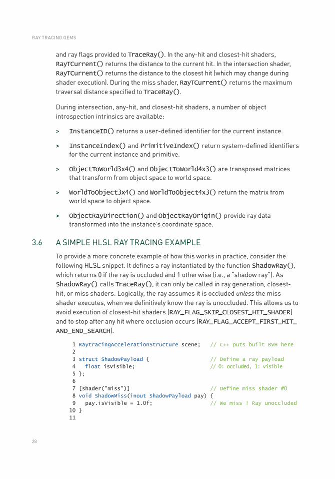
To provide a more concrete example of how this works in practice, consider the following HLSL snippet. It defines a ray instantiated by the function ShadowRay(), which returns 0 if the ray is occluded and 1 otherwise (i.e., a “shadow ray”). As ShadowRay() calls TraceRay(), it can only be called in ray generation, closest-hit, or miss shaders. Logically, the ray assumes it is occluded unless the miss shader executes, when we definitively know the ray is unoccluded. This allows us to avoid execution of closest-hit shaders (RAY_FLAG_SKIP_CLOSEST_HIT_SHADER) and to stop after any hit where occlusion occurs (RAY_FLAG_ACCEPT_FIRST_HIT_AND_END_SEARCH).
1 RaytracingAccelerationStructure scene; // C++ puts built BVH here
2
3 struct ShadowPayload { // Define a ray payload
4 float isVisible; // 0: occluded, 1: visible
5 };
6
7 [shader("miss")] // Define miss shader #0
8 void ShadowMiss(inout ShadowPayload pay) {
9 pay.isVisible = 1.0f; // We miss ! Ray unoccluded
10 }
11
RAY TRACING GEMS
29
12 [shader("anyhit")] // Add to hit group #0
13 void ShadowAnyHit(inout ShadowPayload pay,
14 BuiltInTriangleIntersectionAttributes attrib) {
15 if ( isTransparent( attrib, PrimitiveIndex() ) )
16 IgnoreHit(); // Skip transparent hits
17 }
18
19 float ShadowRay( float3 orig, float3 dir, float minT, float maxT ) {
20 RayDesc ray = { orig, minT, dir, maxT }; // Define our new ray.
21 ShadowPayload pay = { 0.0f }; // Assume ray is occluded
22 TraceRay( scene,
23 (RAY_FLAG_SKIP_CLOSEST_HIT_SHADER |
24 RAY_FLAG_ACCEPT_FIRST_HIT_AND_END_SEARCH),
25 0xFF, 0, 1, 0, ray, pay ); // Hit group 0; miss 0
26 return pay.isVisible; // Return ray payload
27 }
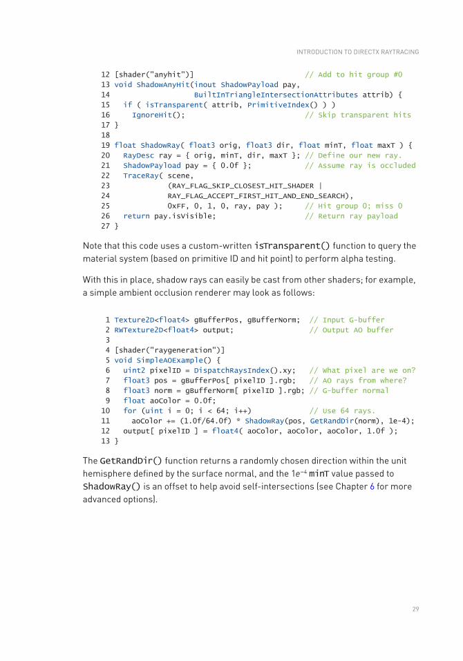
Note that this code uses a custom-written isTransparent() function to query the material system (based on primitive ID and hit point) to perform alpha testing.
With this in place, shadow rays can easily be cast from other shaders; for example, a simple ambient occlusion renderer may look as follows:
1 Texture2D<float4> gBufferPos, gBufferNorm; // Input G-buffer
2 RWTexture2D<float4> output; // Output AO buffer
3
4 [shader("raygeneration")]
5 void SimpleAOExample() {
6 uint2 pixelID = DispatchRaysIndex().xy; // What pixel are we on?
7 float3 pos = gBufferPos[ pixelID ].rgb; // AO rays from where?
8 float3 norm = gBufferNorm[ pixelID ].rgb; // G-buffer normal
9 float aoColor = 0.0f;
10 for (uint i = 0; i < 64; i++) // Use 64 rays.
11 aoColor += (1.0f/64.0f) * ShadowRay(pos, GetRandDir(norm), 1e-4);
12 output[ pixelID ] = float4( aoColor, aoColor, aoColor, 1.0f );
13 }
The GetRandDir() function returns a randomly chosen direction within the unit hemisphere defined by the surface normal, and the 1e−4 minT value passed to ShadowRay() is an offset to help avoid self-intersections (see Chapter 6 for more advanced options).
INTRODUCTION TO DIRECTX RAYTRACING
30
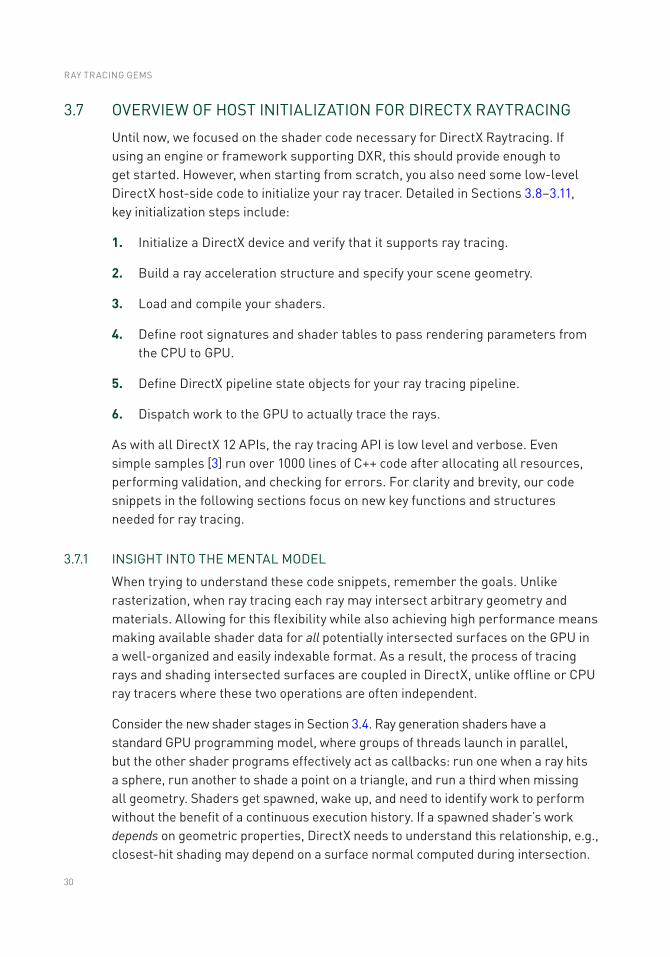
3.7 OVERVIEW OF HOST INITIALIZATION FOR DIRECTX RAYTRACING
Until now, we focused on the shader code necessary for DirectX Raytracing. If using an engine or framework supporting DXR, this should provide enough to get started. However, when starting from scratch, you also need some low-level DirectX host-side code to initialize your ray tracer. Detailed in Sections 3.8–3.11, key initialization steps include:
1. Initialize a DirectX device and verify that it supports ray tracing.
2. Build a ray acceleration structure and specify your scene geometry.
3. Load and compile your shaders.
4. Define root signatures and shader tables to pass rendering parameters from the CPU to GPU.
5. Define DirectX pipeline state objects for your ray tracing pipeline.
6. Dispatch work to the GPU to actually trace the rays.
As with all DirectX 12 APIs, the ray tracing API is low level and verbose. Even simple samples [3] run over 1000 lines of C++ code after allocating all resources, performing validation, and checking for errors. For clarity and brevity, our code snippets in the following sections focus on new key functions and structures needed for ray tracing.
3.7.1 INSIGHT INTO THE MENTAL MODEL
When trying to understand these code snippets, remember the goals. Unlike rasterization, when ray tracing each ray may intersect arbitrary geometry and materials. Allowing for this flexibility while also achieving high performance means making available shader data for all potentially intersected surfaces on the GPU in a well- organized and easily indexable format. As a result, the process of tracing rays and shading intersected surfaces are coupled in DirectX, unlike offline or CPU ray tracers where these two operations are often independent.
Consider the new shader stages in Section 3.4. Ray generation shaders have a standard GPU programming model, where groups of threads launch in parallel, but the other shader programs effectively act as callbacks: run one when a ray hits a sphere, run another to shade a point on a triangle, and run a third when missing all geometry. Shaders get spawned, wake up, and need to identify work to perform without the benefit of a continuous execution history. If a spawned shader’s work depends on geometric properties, DirectX needs to understand this relationship, e.g., closest-hit shading may depend on a surface normal computed during intersection.
RAY TRACING GEMS
31
What information is needed to identify the correct shader to run for a surface? Depending on the complexity of your ray tracer, shaders may vary based on:
> Ray type: Rays may need different computations (e.g., shadowing).
> Primitive type: Triangles, spheres, cones, etc. may have different needs.
> Primitive identifier: Each primitive may use a different material.
> Instance identifier: Instancing may change the required shading.
In practice, shader selection by the DirectX runtime is a combination of parameters provided to TraceRay(), geometric information, and per-instance data.
To efficiently implement the flexible tracing and shading operations required by real- time ray tracing, DXR introduces two new data structures: the acceleration structure and shader table. Shader tables are especially important because they serve as the glue tying rays, geometry, and shading operations together. We talk about each of these in detail in Sections 3.8.1 and 3.10.
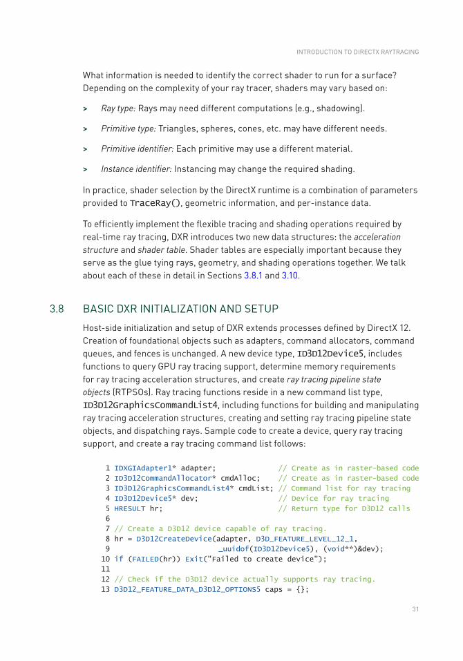
3.8 BASIC DXR INITIALIZATION AND SETUP
Host-side initialization and setup of DXR extends processes defined by DirectX 12. Creation of foundational objects such as adapters, command allocators, command queues, and fences is unchanged. A new device type, ID3D12Device5, includes functions to query GPU ray tracing support, determine memory requirements for ray tracing acceleration structures, and create ray tracing pipeline state objects (RTPSOs). Ray tracing functions reside in a new command list type, ID3D12GraphicsCommandList4, including functions for building and manipulating ray tracing acceleration structures, creating and setting ray tracing pipeline state objects, and dispatching rays. Sample code to create a device, query ray tracing support, and create a ray tracing command list follows:
1 IDXGIAdapter1* adapter; // Create as in raster-based code
2 ID3D12CommandAllocator* cmdAlloc; // Create as in raster-based code
3 ID3D12GraphicsCommandList4* cmdList; // Command list for ray tracing
4 ID3D12Device5* dev; // Device for ray tracing
5 HRESULT hr; // Return type for D3D12 calls
6
7 // Create a D3D12 device capable of ray tracing.
8 hr = D3D12CreateDevice(adapter, D3D_FEATURE_LEVEL_12_1,
9 _uuidof(ID3D12Device5), (void**)&dev);
10 if (FAILED(hr)) Exit("Failed to create device");
11
12 // Check if the D3D12 device actually supports ray tracing.
13 D3D12_FEATURE_DATA_D3D12_OPTIONS5 caps = {};
INTRODUCTION TO DIRECTX RAYTRACING
32
14 hr = dev->CheckFeatureSupport(D3D12_FEATURE_D3D12_OPTIONS5,
15 &caps, sizeof(caps));
16
17 if (FAILED(hr) || caps.RaytracingTier < D3D12_RAYTRACING_TIER_1_0)
18 Exit("Device or driver does not support ray tracing!");
19
20 // Create a command list that supports ray tracing.
21 hr = dev->CreateCommandList(0, D3D12_COMMAND_LIST_TYPE_DIRECT,
22 cmdAlloc, nullptr, IID_PPV_ARGS(& cmdList));
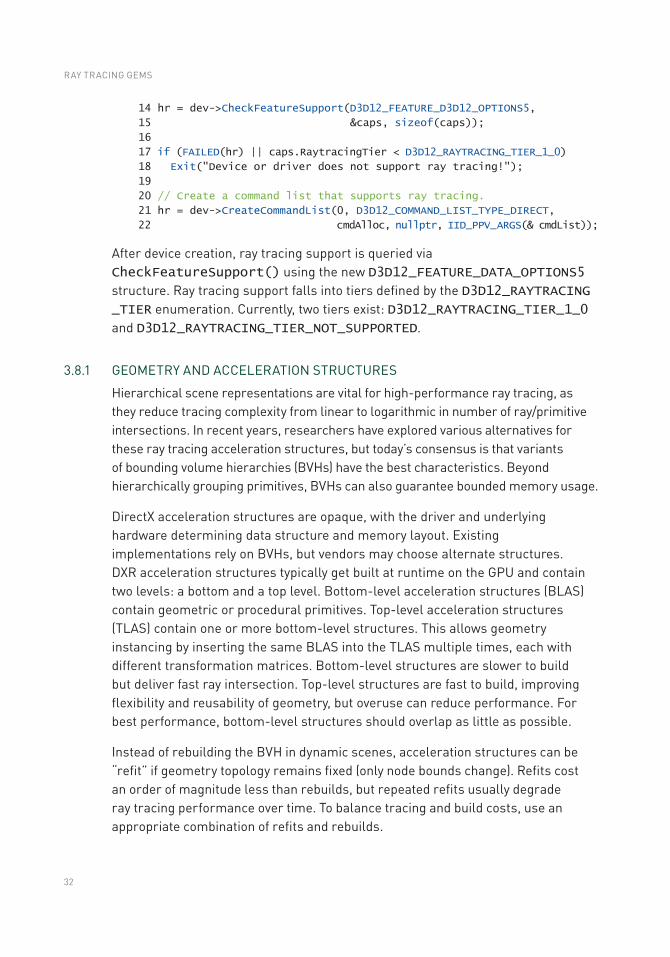
After device creation, ray tracing support is queried via CheckFeatureSupport() using the new D3D12_FEATURE_DATA_OPTIONS5 structure. Ray tracing support falls into tiers defined by the D3D12_RAYTRACING _TIER enumeration. Currently, two tiers exist: D3D12_RAYTRACING_TIER_1_0 and D3D12_RAYTRACING_TIER_NOT_SUPPORTED.
3.8.1 GEOMETRY AND ACCELERATION STRUCTURES
Hierarchical scene representations are vital for high-performance ray tracing, as they reduce tracing complexity from linear to logarithmic in number of ray/primitive intersections. In recent years, researchers have explored various alternatives for these ray tracing acceleration structures, but today’s consensus is that variants of bounding volume hierarchies (BVHs) have the best characteristics. Beyond hierarchically grouping primitives, BVHs can also guarantee bounded memory usage.
DirectX acceleration structures are opaque, with the driver and underlying hardware determining data structure and memory layout. Existing implementations rely on BVHs, but vendors may choose alternate structures. DXR acceleration structures typically get built at runtime on the GPU and contain two levels: a bottom and a top level. Bottom- level acceleration structures (BLAS) contain geometric or procedural primitives. Top- level acceleration structures (TLAS) contain one or more bottom-level structures. This allows geometry instancing by inserting the same BLAS into the TLAS multiple times, each with different transformation matrices. Bottom-level structures are slower to build but deliver fast ray intersection. Top-level structures are fast to build, improving flexibility and reusability of geometry, but overuse can reduce performance. For best performance, bottom-level structures should overlap as little as possible.
Instead of rebuilding the BVH in dynamic scenes, acceleration structures can be “refit” if geometry topology remains fixed (only node bounds change). Refits cost an order of magnitude less than rebuilds, but repeated refits usually degrade ray tracing performance over time. To balance tracing and build costs, use an appropriate combination of refits and rebuilds.
RAY TRACING GEMS
33
3.8.1.1 BOTTOM-LEVEL ACCELERATION STRUCTURE
To create an acceleration structure, start by building the bottom levels. First, use D3D12_RAYTRACING_GEOMETRY_DESC structures to specify the vertex, index, and transformation data of geometry contained in the bottom-level structure. Note that ray tracing vertex and index buffers are not special, but are identical to the buffers used in rasterization. An example showing how to specify opaque geometry follows:
1 struct Vertex {
2 XMFLOAT3 position;
3 XMFLOAT2 uv;
4 };
5
6 vector<Vertex> vertices;
7 vector<UINT> indices;
8 ID3D12Resource* vb; // Vertex buffer
9 ID3D12Resource* ib; // Index buffer
10
11 // Describe the geometry.
12 D3D12_RAYTRACING_GEOMETRY_DESC geometry;
13 geometry.Type = D3D12_RAYTRACING_GEOMETRY_TYPE_TRIANGLES;
14 geometry.Triangles.VertexBuffer.StartAddress =
15 vb->GetGPUVirtualAddress();
16 geometry.Triangles.VertexBuffer.StrideInBytes = sizeof(Vertex);
17 geo metry.Triangles.VertexCount = static_cast<UINT>(vertices.size());
18 geometry.Triangles.VertexFormat = DXGI_FORMAT_R32G32B32_FLOAT;
19 geometry.Triangles.IndexBuffer = ib->GetGPUVirtualAddress();
20 geometry.Triangles.IndexFormat = DXGI_FORMAT_R32_UINT;
21 geometry.Triangles.IndexCount = static_cast<UINT>(indices.size());
22 geometry.Triangles.Transform3x4 = 0;
23 geometry.Flags = D3D12_RAYTRACING_GEOMETRY_FLAG_OPAQUE;
When describing BLAS geometry, use flags to inform ray tracing shaders about the geometry. For example, as we saw in Section 3.6, it is useful for shaders to know if intersected geometry is opaque or transparent. If geometry is opaque, specify D3D12_RAYTRACING_GEOMETRY_FLAG_OPAQUE; otherwise, specify *_FLAG_NONE.
Next, query the memory needed to build the BLAS and store the fully built structure. Use the new GetRaytracingAccelerationStructurePrebuildInfo() device function to get sizes for the scratch and result buffers. The scratch buffer is used during the build process, and the result buffer stores the completed BLAS.
Build flags describe expected BLAS usage, allowing memory and performance optimizations. The D3D12_RAYTRACING_ACCELERATION_STRUCTURE_BUILD_FLAG_MINIMIZE_MEMORY and *_ALLOW_COMPACTION flags help reduce required
INTRODUCTION TO DIRECTX RAYTRACING

34
memory. Other flags request additional desirable characteristics, such as faster tracing or build time (*_PREFER_FAST_TRACE or *_PREFER_FAST_BUILD) or allowing dynamic BVH refits (*_ALLOW_UPDATE). Here is a simple example:
1 // Describe the bottom-level acceleration structure inputs.
2 D3D12_BUILD_RAYTRACING_ACCELERATION_STRUCTURE_INPUTS ASInputs = {};
3 ASInputs.Type =
4 D3D12_RAYTRACING_ACCELERATION_STRUCTURE_TYPE_BOTTOM_LEVEL;
5 ASInputs.DescsLayout = D3D12_ELEMENTS_LAYOUT_ARRAY;
6
7 // From previous code snippet
8 ASInputs.pGeometryDescs = &geometry;
9
10 ASInputs.NumDescs = 1;
11 ASInputs.Flags =
12 D3D12_RAYTRACING_ACCELERATION_STRUCTURE_BUILD_FLAG_PREFER_FAST_TRACE;
13
14 // Get the memory requirements to build the BLAS.
15 D3D12_RAYTRACING_ACCELERATION_STRUCTURE_PREBUILD_INFO ASBuildInfo = {};
16 dev->GetRaytracingAccelerationStructurePrebuildInfo(
17 &ASInputs, &ASBuildInfo);
After determining the memory required, allocate GPU buffers for the BLAS. Both scratch and result buffers must support unordered access view (UAV), set with the D3D12_RESOURCE_FLAG_ALLOW_UNORDERED_ACCESS flag. Use D3D12_RESOURCE_STATE_RAYTRACING_ACCELERATION_STRUCTURE as the initial state for the final BLAS buffer. With geometry specified and BLAS memory allocated, we can build our acceleration structure. This looks as follows:
1 ID3D12Resource* blasScratch; // Create as described in text.
2 ID3D12Resource* blasResult; // Create as described in text.
3
4 // Describe the bottom-level acceleration structure.
5 D3D12_BUILD_RAYTRACING_ACCELERATION_STRUCTURE_DESC desc = {};
6 desc.Inputs = ASInputs; // From previous code snippet
7
8 desc.ScratchAccelerationStructureData =
9 blasScratch->GetGPUVirtualAddress();
10 desc.DestAccelerationStructureData =
11 blasResult->GetGPUVirtualAddress();
12
13 // Build the bottom-level acceleration structure.
14 cmdList->BuildRaytracingAccelerationStructure(&desc, 0, nullptr);
Since the BLAS may build asynchronously on the GPU, wait until building completes before using it. To do this, add a UAV barrier to the command list referencing the BLAS result buffer.
RAY TRACING GEMS
35
3.8.1.2 TOP-LEVEL ACCELERATION STRUCTURE
Building the TLAS is similar to building bottom-level structures, with a few small but important changes. Instead of providing geometry descriptions, each TLAS contains instances of geometry from a BLAS. Each instance has a mask that allows for rejecting entire instances on a per-ray basis, without any primitive intersections, in conjunction with parameters to TraceRay() (see Section 3.5.1). For example, an instance mask could disable shadowing on a per-object basis. Instances can each uniquely transform the BLAS geometry. Additional flags allow overrides to transparency, frontface winding, and culling. The following example code defines TLAS instances:
1 // Describe the top-level acceleration structure instance(s).
2 D3D12_RAYTRACING_INSTANCE_DESC instances = {};
3 // Available in shaders
4 instances.InstanceID = 0;
5 // Choose hit group shader
6 instances.InstanceContributionToHitGroupIndex = 0;
7 // Bitwise AND with TraceRay() parameter
8 instances.InstanceMask = 1;
9 instances.Transform = &identityMatrix;
10 // Transparency? Culling?
11 instances.Flags = D3D12_RAYTRACING_INSTANCE_FLAG_NONE;
12 instances.AccelerationStructure = blasResult->GetGPUVirtualAddress();
After creating instance descriptions, upload them in a GPU buffer. Reference this buffer as a TLAS input when querying memory requirements. As with a BLAS, query memory needs using GetRaytracingAccelerationStructurePrebuildInfo(), but specify TLAS construction using type D3D12_RAYTRACING_ACCELERATION_STRUCTURE_TYPE_TOP_LEVEL. Next, allocate scratch and result buffers and then call BuildRaytracingAccelerationStructure() to build the TLAS. As with the bottom level, placing a UAV barrier on the top-level result buffer ensures the acceleration structure build is complete before use.
3.8.2 ROOT SIGNATURES
Similar to function signatures in C++, DirectX 12 root signatures define the parameters that are passed to shader programs. These parameters store information used to locate resources (such as buffers, textures, or constants) that reside in GPU memory. DXR root signatures derive from existing DirectX root signatures, with two notable changes. First, ray tracing shaders may use either local or global root signatures. Local root signatures pull data from the DXR shader table (see Section 3.10) and initialize the D3D12_ROOT_SIGNATURE_DESC structure using the D3D12_ROOT_SIGNATURE_FLAG_LOCAL_ROOT_SIGNATURE flag. This flag only applies to ray tracing, so avoid
INTRODUCTION TO DIRECTX RAYTRACING
36
combining it with other signature flags. Global root signatures source data from DirectX command lists, require no special flags, and can be shared between graphics, compute, and ray tracing. The distinction between local and global signatures is useful to separate resources with varying update rates (e.g., per-primitive versus per-frame).
Second, all ray tracing shaders should use D3D12_SHADER_VISIBILITY_ALL for the visibility parameter in D3D12_ROOT_PARAMETER, using either local or global root signatures. As ray tracing root signatures share the command list state with compute, local root arguments are always visible to all ray tracing shaders. It is not possible to further narrow visibility.
3.8.3 SHADER COMPILATION
After building acceleration structures and defining root signatures, load and compile shaders with the DirectX shader compiler (dxc) [7]. Initialize the compiler using various helpers:
1 dxc::DxcDllSupport dxcHelper;
2 IDxcCompiler* compiler;
3 IDxcLibrary* library;
4 CComPtr<IDxcIncludeHandler> dxcIncludeHandler;
5
6 dxcHelper.Initialize();
7 dxcHelper.CreateInstance(CLSID_DxcCompiler, &compiler);
8 dxcHelper.CreateInstance(CLSID_DxcLibrary, &library);
9 library->CreateIncludeHandler(&dxcIncludeHandler);
Next, use the IDxcLibrary class to load your shader source. This helper class compiles the shader code; specify lib_6_3 as the target profile. Compiled DirectX intermediate language (DXIL) bytecode gets stored in a IDxcBlob, which we use later to set up our ray tracing pipeline state object. As most applications use many shaders, encapsulating compilation into a helper function is useful. We show such a function and its usage in the following:
1 void CompileShader(IDxcLibrary* lib, IDxcCompiler* comp,
2 LPCWSTR fileName, IDxcBlob** blob)
3 {
4 UINT32 codePage(0);
5 IDxcBlobEncoding* pShaderText(nullptr);
6 IDxcOperationResult* result;
7
8 // Load and encode the shader file.
9 lib->CreateBlobFromFile(fileName, & codePage, & pShaderText);
10
11 // Compile shader; "main" is where execution starts.
12 comp->Compile(pShaderText, fileName, L"main", "lib_6_3",
13 nullptr, 0, nullptr, 0, dxcIncludeHandler, &result);
14
RAY TRACING GEMS
37
15 // Get the shader bytecode result.
16 result->GetResult(blob);
17 }
18
19 // Compiled shader DXIL bytecode
20 IDxcBlob *rgsBytecode, *missBytecode, *chsBytecode, *ahsBytecode;
21
22 // Call our helper function to compile the ray tracing shaders.
23 CompileShader(library, compiler, L"RayGen.hlsl", &rgsBytecode);
24 CompileShader(library, compiler, L"Miss.hlsl", &missBytecode);
25 CompileShader(library, compiler, L"ClosestHit.hlsl", &chsBytecode);
26 CompileShader(library, compiler, L"AnyHit.hlsl", &ahsBytecode);
3.9 RAY TRACING PIPELINE STATE OBJECTS
As rays can intersect anything in a scene, applications must specify in advance every shader that can execute. Similar to pipeline state objects (PSOs) in a raster pipeline, the new ray tracing pipeline state objects (RTPSOs) provide the DXR runtime with the full set of shaders and configuration information before execution. This reduces driver complexity and enables shader scheduling optimizations.
To construct an RTPSO, initialize a D3D12_STATE_OBJECT_DESC. There are two pipeline object types: a ray tracing pipeline (D3D12_STATE_OBJECT_TYPE_RAYTRACING_PIPELINE) and a collection (D3D12_STATE_OBJECT_TYPE _COLLECTION). Collections are useful for parallel compilation of ray tracing shaders across multiple threads.
DXR ID3D12StateObjects are composed of many subobjects defining the pipeline’s shaders, root signatures, and configuration data. Construct those using various D3D12_STATE_SUBOBJECTs, and create objects by calling the CreateStateObject() device function. Query properties of RTPSOs, such as shader identifiers (see Section 3.10), using the ID3D12StateObjectProperties type. An example of this process follows:
1 ID3D12StateObject* rtpso;
2 ID3D12StateObjectProperties* rtpsoInfo;
3
4 // Define state subobjects for shaders, root signatures,
5 // and configuration data.
6 vector<D3D12_STATE_SUBOBJECT> subobjects;
7 //...
8
9 // Describe the ray tracing pipeline state object.
INTRODUCTION TO DIRECTX RAYTRACING
38
10 D3D12_STATE_OBJECT_DESC rtpsoDesc = {};
11 rtpsoDesc.Type = D3D12_STATE_OBJECT_TYPE_RAYTRACING_PIPELINE;
12 rtpsoDesc.NumSubobjects = static_cast<UINT>(subobjects.size());
13 rtpsoDesc.pSubobjects = subobjects.data();
14
15 // Create the ray tracing pipeline state object.
16 dev->CreateStateObject(&rtpsoDesc, IID_PPV_ARGS(&rtpso));
17
18 // Get the ray tracing pipeline state object's properties.
19 rtpso->QueryInterface(IID_PPV_ARGS(&rtpsoInfo));
A ray tracing pipeline contains many different subobject types, including possible subobjects for local and global root signatures, GPU node masks, shaders, collections, shader configuration, and pipeline configuration. We cover only key subobjects, but DXR provides lots of flexibility for more complex cases; please consult the specification for comprehensive details.
Use D3D12_STATE_SUBOBJECT_TYPE_DXIL_LIBRARY to create subobjects for shaders. Use the compiled bytecode IDxcBlob (from Section 3.8.3) to provide a shader pointer and the compiled size. Use D3D12_EXPORT_DESC to specify the shader’s entry point and a unique shader identifier. Importantly, shader entry points must have unique names within an RTPSO. If multiple shaders reuse identical function names, put the name into the ExportToRename field, and create a new unique name in the Name field. The following shows an example:
1 // Describe the DXIL Library entry point and name.
2 D3D12_EXPORT_DESC rgsExportDesc = {};
3 // Unique name (to reference elsewhere)
4 rgsExportDesc.Name = L"Unique_RGS_Name";
5 // Entry point in HLSL shader source
6 rgsExportDesc.ExportToRename = L"RayGen";
7 rgsExportDesc.Flags = D3D12_EXPORT_FLAG_NONE;
8
9 // Describe the DXIL library.
10 D3D12_DXIL_LIBRARY_DESC libDesc = {};
11 libDesc.DXILLibrary.BytecodeLength = rgsBytecode->GetBufferSize();
12 libDesc.DXILLibrary.pShaderBytecode = rgsBytecode->GetBufferPointer();
13 libDesc.NumExports = 1;
14 libDesc.pExports = &rgsExportDesc;
15
16 // Describe the ray generation shader state subobject.
17 D3D12_STATE_SUBOBJECT rgs = {};
18 rgs.Type = D3D12_STATE_SUBOBJECT_TYPE_DXIL_LIBRARY;
19 rgs.pDesc = &libDesc;
Create subobjects for miss, closest-hit, and any-hit shaders similarly. Groups of intersection, any-hit, and closest-hit shaders form hit groups. These shaders get executed once BVH traversal reaches a leaf node, depending on the primitives in
RAY TRACING GEMS
39
the leaf. We need to create subobjects for each such cluster. Unique shader names specified in D3D12_EXPORT_DESC are used to “import” shaders into a hit group:
1 // Describe the hit group.
2 D3D12_HIT_GROUP_DESC hitGroupDesc = {};
3 hitGroupDesc.ClosestHitShaderImport = L"Unique_CHS_Name";
4 hitGroupDesc.AnyHitShaderImport = L"Unique_AHS_Name";
5 hitGroupDesc.IntersectionShaderImport = L"Unique_IS_Name";
6 hitGroupDesc.HitGroupExport = L"HitGroup_Name";
7
8 // Describe the hit group state subobject.
9 D3D12_STATE_SUBOBJECT hitGroup = {};
10 hitGroup.Type = D3D12_STATE_SUBOBJECT_TYPE_HIT_GROUP;
11 hitGroup.pDesc = &hitGroupDesc;
User-defined payload and attribute structures pass data between shaders. Allocate runtime space for these structures using a D3D12_STATE_SUBOBJECT_TYPE_RAYTRACING_SHADER_CONFIG subobject and D3D12_RAYTRACING_SHADER_CONFIG to describe the sizes. Attribute structures have a relatively small DirectX-defined maximum size that you cannot exceed (currently 32 bytes).
1 // Describe the shader configuration.
2 D3D12_RAYTRACING_SHADER_CONFIG shdrConfigDesc = {};
3 shdrConfigDesc.MaxPayloadSizeInBytes = sizeof(XMFLOAT4);
4 shdrConfigDesc.MaxAttributeSizeInBytes =
5 D3D12_RAYTRACING_MAX_ATTRIBUTE_SIZE_IN_BYTES;
6
7 // Create the shader configuration state subobject.
8 D3D12_STATE_SUBOBJECT shdrConfig = {};
9 shdrConfig.Type = D3D12_STATE_SUBOBJECT_TYPE_RAYTRACING_SHADER_CONFIG;
10 shdrConfig.pDesc = &shdrConfigDesc;
Configuring shaders requires more than adding a payload subobject to the pipeline state. We must also attach the configuration subobject with associated shaders (this allows payloads of multiple sizes within the same pipeline). After defining a shader configuration, use a D3D12_STATE_SUBOBJECT_TYPE_SUBOBJECT_TO_EXPORTS_ASSOCIATION to specify which entry points from DXIL libraries to associate with a configuration object. An example is shown in the following code:
1 // Create a list of shader entry point names that use the payload.
2 const WCHAR* shaderPayloadExports[] =
3 { L"Unique_RGS_Name", L"HitGroup_Name" };
4
5 // Describe the association between shaders and the payload.
6 D3D12_SUBOBJECT_TO_EXPORTS_ASSOCIATION assocDesc = {};
7 assocDesc.NumExports = _countof(shaderPayloadExports);
8 assocDesc.pExports = shaderPayloadExports;
9 assocDesc.pSubobjectToAssociate = &subobjects[CONFIG_SUBOBJECT_INDEX];
10
INTRODUCTION TO DIRECTX RAYTRACING
40
11 // Create the association state subobject.
12 D3D12_STATE_SUBOBJECT association = {};
13 association.Type =
14 D3D12_STATE_SUBOBJECT_TYPE_SUBOBJECT_TO_EXPORTS_ASSOCIATION;
15 association.pDesc = &assocDesc;
Use D3D12_STATE_SUBOBJECT_TYPE_LOCAL_ROOT_SIGNATURE typed subobjects to specify local root signatures and provide a pointer to the serialized root signature:
1 ID3D12RootSignature* localRootSignature;
2
3 // Create a state subobject for a local root signature.
4 D3D12_STATE_SUBOBJECT localRootSig = {};
5 localRootSig.Type = D3D12_STATE_SUBOBJECT_TYPE_LOCAL_ROOT_SIGNATURE;
6 localRootSig.pDesc = &localRootSignature;
As with shader configurations, we must associate local root signatures and their shaders. Do this using the same pattern as the shader payload association above. With a D3D12_SUBOBJECT_TO_EXPORTS_ASSOCIATION subobject, provide a shader name and the associated subobject pointer, in this case to a local root signature. Global root signatures do not require association subobjects, so simply create a D3D12_STATE_SUBOBJECT_TYPE_GLOBAL_ROOT_SIGNATURE subobject and point to the serialized global root signature.
1 // Create a list of shader export names that use the root signature.
2 const WCHAR* lrsExports[] =
3 { L"Unique_RGS_Name", L"Unique_Miss_Name", L"HitGroup_Name" };
4
5 // Describe the association of shaders and a local root signature.
6 D3D12_SUBOBJECT_TO_EXPORTS_ASSOCIATION assocDesc = {};
7 assocDesc.NumExports = _countof(lrsExports);
8 assocDesc.pExports = lrsExports;
9 assocDesc.pSubobjectToAssociate =
10 &subobjects[ROOT_SIGNATURE_SUBOBJECT_INDEX];
11
12 // Create the association subobject.
13 D3D12_STATE_SUBOBJECT association = {};
14 association.Type =
15 D3D12_STATE_SUBOBJECT_TYPE_SUBOBJECT_TO_EXPORTS_ASSOCIATION;
16 association.pDesc = &assocDesc;
RAY TRACING GEMS
41
All executable ray tracing pipeline objects must include a pipeline configuration subobject of type D3D12_STATE_SUBOBJECT_TYPE_RAYTRACING_PIPELINE _CONFIG. Describe the configuration using a D3D12_RAYTRACING_PIPELINE _CONFIG structure, which sets the maximum depth of recursive rays. Setting a maximum recursion helps guarantee that execution will complete and provides information to the driver for potential optimizations. Lower recursion limits can improve performance. Here is an example:
1 // Describe the ray tracing pipeline configuration.
2 D3D12_RAYTRACING_PIPELINE_CONFIG pipelineConfigDesc = {};
3 pipelineConfigDesc.MaxTraceRecursionDepth = 1;
4
5 // Create the ray tracing pipeline configuration state subobject.
6 D3D12_STATE_SUBOBJECT pipelineConfig = {};
7 pipelineConfig.Type =
8 D3D12_STATE_SUBOBJECT_TYPE_RAYTRACING_PIPELINE_CONFIG;
9 pipelineConfig.pDesc = &pipelineConfigDesc;
After creating the ray tracing pipeline state object and all associated subobjects, we can move on to building a shader table (Section 3.10). We will query the ID3D12StateObjectProperties object for details needed to construct shader table records.
3.10 SHADER TABLES
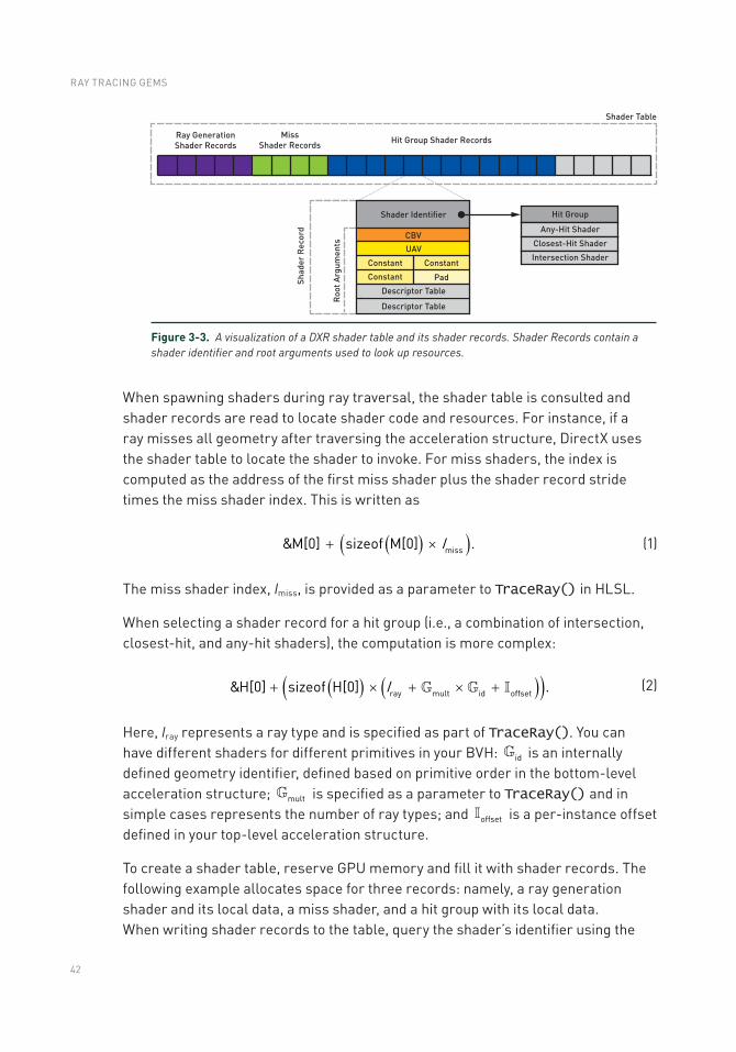
Shader tables are contiguous blocks of 64-bit aligned GPU memory containing ray tracing shader data and scene resource bindings. Illustrated in Figure 3-3, shader tables are filled with shader records. Shader records contain a unique shader identifier and root arguments defined by the shader’s local root signature. Shader identifiers are 32-bit chunks of data generated by an RTPSO and act as a pointer to a shader or hit group. Since shader tables are simply GPU memory owned and modified directly by the application, their layout and organization are incredibly flexible. As a result, the organization shown in Figure 3-3 is just one of many ways the records in a shader table may be arranged.
INTRODUCTION TO DIRECTX RAYTRACING
42
When spawning shaders during ray traversal, the shader table is consulted and shader records are read to locate shader code and resources. For instance, if a ray misses all geometry after traversing the acceleration structure, DirectX uses the shader table to locate the shader to invoke. For miss shaders, the index is computed as the address of the first miss shader plus the shader record stride times the miss shader index. This is written as
( )( )Imiss&M[0] sizeof M[0] .+ ´
(1)
The miss shader index, Imiss, is provided as a parameter to TraceRay() in HLSL.
When selecting a shader record for a hit group (i.e., a combination of intersection, closest-hit, and any-hit shaders), the computation is more complex:
( ) ( )( )ray mult id offset&H[0] sizeof H[0] .I+ ´ + ´ +
(2)
Here, Iray represents a ray type and is specified as part of TraceRay(). You can have different shaders for different primitives in your BVH: id is an internally defined geometry identifier, defined based on primitive order in the bottom-level acceleration structure; mult is specified as a parameter to TraceRay() and in simple cases represents the number of ray types; and offset is a per-instance offset defined in your top-level acceleration structure.
To create a shader table, reserve GPU memory and fill it with shader records. The following example allocates space for three records: namely, a ray generation shader and its local data, a miss shader, and a hit group with its local data. When writing shader records to the table, query the shader’s identifier using the
Figure 3-3. A visualization of a DXR shader table and its shader records. Shader Records contain a shader identifier and root arguments used to look up resources.
RAY TRACING GEMS
43
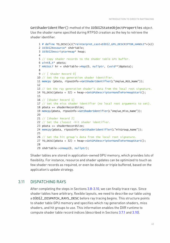
GetShaderIdentifier() method of the ID3D12StateObjectProperties object. Use the shader name specified during RTPSO creation as the key to retrieve the shader identifier.
1 # define TO_DESC(x)(*reinterpret_cast<D3D12_GPU_DESCRIPTOR_HANDLE*>(x))
2 ID3D12Resource* shdrTable;
3 ID3D12DescriptorHeap* heap;
4
5 // Copy shader records to the shader table GPU buffer.
6 uint8_t* pData;
7 HRESULT hr = shdrTable->Map(0, nullptr, (void**)&pData);
8
9 // [ Shader Record 0]
10 // Set the ray generation shader identifier.
11 memcpy (pData, rtpsoInfo->GetShaderIdentifier(L"Unqiue_RGS_Name"));
12
13 // Set the ray generation shader's data from the local root signature.
14 TO_DESC(pData + 32) = heap->GetGPUDescriptorHandleForHeapStart();
15
16 // [Shader Record 1]
17 // Set the miss shader identifier (no local root arguments to set).
18 pData += shaderRecordSize;
19 memcpy(pData, rtpsoInfo->GetShaderIdentifier(L"Unqiue_Miss_Name"));
20
21 // [Shader Record 2]
22 // Set the closest -hit shader identifier.
23 pData += shaderRecordSize;
24 memcpy(pData, rtpsoInfo->GetShaderIdentifier(L"HitGroup_Name"));
25
26 // Set the hit group's data from the local root signature.
27 TO_DESC(pData + 32) = heap->GetGPUDescriptorHandleForHeapStart();
28
29 shdrTable->Unmap(0, nullptr);
Shader tables are stored in application-owned GPU memory, which provides lots of flexibility. For instance, resource and shader updates can be optimized to touch as few shader records as required, or even be double or triple buffered, based on the application’s update strategy.
3.11 DISPATCHING RAYS
After completing the steps in Sections 3.8-3.10, we can finally trace rays. Since shader tables have arbitrary, flexible layouts, we need to describe our table using a D3D12_DISPATCH_RAYS_DESC before ray tracing begins. This structure points to shader table GPU memory and specifies which ray generation shaders, miss shaders, and hit groups to use. This information enables the DXR runtime to compute shader table record indices (described in Sections 3.7.1 and 3.10).
INTRODUCTION TO DIRECTX RAYTRACING
44
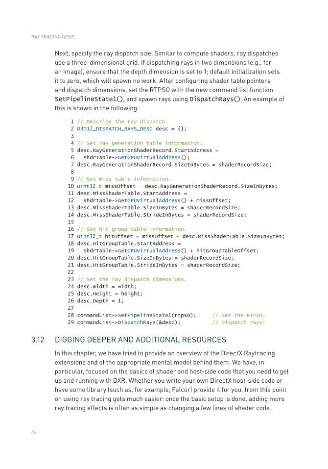
Next, specify the ray dispatch size. Similar to compute shaders, ray dispatches use a three-dimensional grid. If dispatching rays in two dimensions (e.g., for an image), ensure that the depth dimension is set to 1; default initialization sets it to zero, which will spawn no work. After configuring shader table pointers and dispatch dimensions, set the RTPSO with the new command list function SetPipelineState1(), and spawn rays using DispatchRays(). An example of this is shown in the following:
1 // Describe the ray dispatch.
2 D3D12_DISPATCH_RAYS_DESC desc = {};
3
4 // Set ray generation table information.
5 desc.RayGenerationShaderRecord.StartAddress =
6 shdrTable->GetGPUVirtualAddress();
7 desc.RayGenerationShaderRecord.SizeInBytes = shaderRecordSize;
8
9 // Set miss table information.
10 uint32_t missOffset = desc.RayGenerationShaderRecord.SizeInBytes;
11 desc.MissShaderTable.StartAddress =
12 shdrTable->GetGPUVirtualAddress() + missOffset;
13 desc.MissShaderTable.SizeInBytes = shaderRecordSize;
14 desc.MissShaderTable.StrideInBytes = shaderRecordSize;
15
16 // Set hit group table information.
17 uint32_t hitOffset = missOffset + desc.MissShaderTable.SizeInBytes;
18 desc.HitGroupTable.StartAddress =
19 shdrTable->GetGPUVirtualAddress() + hitGroupTableOffset;
20 desc.HitGroupTable.SizeInBytes = shaderRecordSize;
21 desc.HitGroupTable.StrideInBytes = shaderRecordSize;
22
23 // Set the ray dispatch dimensions.
24 desc.Width = width;
25 desc.Height = height;
26 desc.Depth = 1;
27
28 commandList->SetPipelineState1(rtpso); // Set the RTPSO.
29 commandList->DispatchRays(&desc); // Dispatch rays!
3.12 DIGGING DEEPER AND ADDITIONAL RESOURCES
In this chapter, we have tried to provide an overview of the DirectX Raytracing extensions and of the appropriate mental model behind them. We have, in particular, focused on the basics of shader and host-side code that you need to get up and running with DXR. Whether you write your own DirectX host-side code or have some library (such as, for example, Falcor) provide it for you, from this point on using ray tracing gets much easier: once the basic setup is done, adding more ray tracing effects is often as simple as changing a few lines of shader code.
RAY TRACING GEMS
45
Obviously, our limited-length introductory chapter cannot go into greater depth. We encourage you to explore various other resources that provide basic DirectX infrastructure code, samples, best practices, and performance tips.
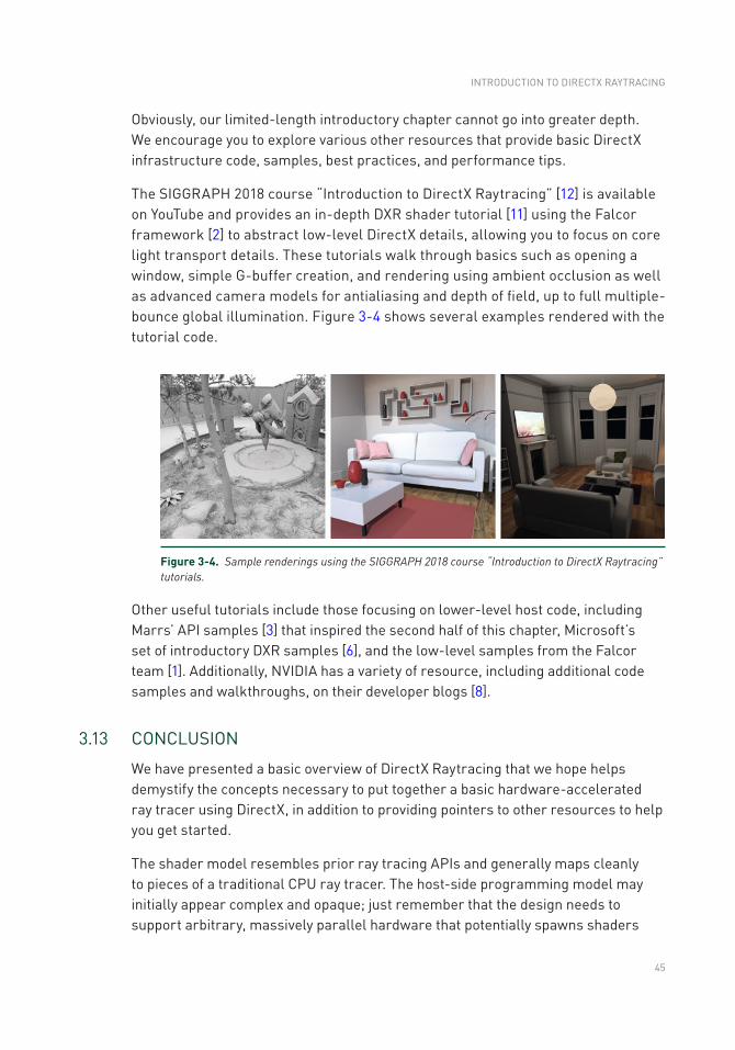
The SIGGRAPH 2018 course “Introduction to DirectX Raytracing” [12] is available on YouTube and provides an in-depth DXR shader tutorial [11] using the Falcor framework [2] to abstract low-level DirectX details, allowing you to focus on core light transport details. These tutorials walk through basics such as opening a window, simple G-buffer creation, and rendering using ambient occlusion as well as advanced camera models for antialiasing and depth of field, up to full multiple-bounce global illumination. Figure 3-4 shows several examples rendered with the tutorial code.
Figure 3-4. Sample renderings using the SIGGRAPH 2018 course “Introduction to DirectX Raytracing” tutorials.
Other useful tutorials include those focusing on lower-level host code, including Marrs’ API samples [3] that inspired the second half of this chapter, Microsoft’s set of introductory DXR samples [6], and the low-level samples from the Falcor team [1]. Additionally, NVIDIA has a variety of resource, including additional code samples and walkthroughs, on their developer blogs [8].
3.13 CONCLUSION
We have presented a basic overview of DirectX Raytracing that we hope helps demystify the concepts necessary to put together a basic hardware-accelerated ray tracer using DirectX, in addition to providing pointers to other resources to help you get started.
The shader model resembles prior ray tracing APIs and generally maps cleanly to pieces of a traditional CPU ray tracer. The host-side programming model may initially appear complex and opaque; just remember that the design needs to support arbitrary, massively parallel hardware that potentially spawns shaders
INTRODUCTION TO DIRECTX RAYTRACING
46
without the benefit of a continuous execution history along each ray. New DXR pipeline state objects and shader tables help to specify data and shaders so such GPUs can spawn work arbitrarily as rays traverse the scene.
Given the complexities of DirectX 12 and the flexibility of ray tracing, we were unable to fully cover the API. Our goal was to provide enough information to get started. As you target more complex renderings, you will need to refer to the DXR specification or other documentation for further guidance. In particular, more complex shader compilation, default pipeline subobject settings, system limits, error handling, and tips for optimal performance all will require other references.
Our advice for getting starting: begin simply. Key problems revolve around correctly setting up the ray tracing pipeline state objects and the shader table, and these are much easier to debug with fewer, simple shaders. For example, basic ray traced shadowing or ambient occlusion using a rasterized G-buffer for primary visibility are good starting points.
With DirectX Raytracing and modern GPUs, shooting rays is faster than ever. However, ray tracing is not free. For at least the near future, you can assume at most a few rays per pixel. This means hybrid ray-raster algorithms, antialiasing, denoising, and reconstruction will all be vital to achieve high-quality renderings quickly. Other work in this book provides ideas on some of these topics, but many problems remain unsolved.
REFERENCES
[1] Benty, N. DirectX Raytracing Tutorials. https://github.com/NVIDIAGameWorks/DxrTutorials, 2018. Accessed October 25, 2018.
[2] Benty, N., Yao, K.-H., Foley, T., Kaplanyan, A. S., Lavelle, C., Wyman, C., and Vijay, A. The Falcor Rendering Framework. https://github.com/NVIDIAGameWorks/Falcor, July 2017.
[3] Marrs, A. Introduction to DirectX Raytracing. https://github.com/acmarrs/IntroToDXR, 2018. Accessed October 25, 2018.
[4] Marschner, S., and Shirley, P. Fundamentals of Computer Graphics, fourth ed. CRC Press, 2015.
[5] Microsoft. Programming Guide and Reference for HLSL. https://docs.microsoft.com/en-us/windows/desktop/direct3dhlsl/dx-graphics-hlsl. Accessed October 25, 2018.
[6] Microsoft. D3D12 Raytracing Samples. https://github.com/Microsoft/DirectX- Graphics- Samples/tree/master/Samples/Desktop/D3D12Raytracing, 2018. Accessed October 25, 2018.
[7] Microsoft. DirectX Shader Compiler. https://github.com/Microsoft/DirectXShaderCompiler, 2018. Accessed October 30, 2018.
RAY TRACING GEMS
47
[8] NVIDIA. DirectX Raytracing Developer Blogs. https://devblogs.nvidia.com/tag/dxr/, 2018. Accessed October 25, 2018.
[9] Shirley, P. Ray Tracing in One Weekend. Amazon Digital Services LLC, 2016. https://github.com/petershirley/raytracinginoneweekend.
[10] Suffern, K. Ray Tracing from the Ground Up. A K Peters, 2007.
[11] Wyman, C. A Gentle Introduction To DirectX Raytracing. http://cwyman.org/code/dxrTutors/dxr_tutors.md.html, 2018.
[12] Wyman, C., Hargreaves, S., Shirley, P., and Barré-Brisebois, C. Introduction to DirectX Raytracing. SIGGRAPH Courses, 2018. http://intro-to-dxr.cwyman.org, https://www.youtube.com/watch?v=Q1cuuepVNoY.
Open Access This chapter is licensed under the terms of the Creative Commons Attribution-NonCommercial-NoDerivatives 4.0 International License (http://creativecommons.org/licenses/by-nc-nd/4.0/), which permits any noncommercial use, sharing, distribution and
reproduction in any medium or format, as long as you give appropriate credit to the original author(s) and the source, provide a link to the Creative Commons license and indicate if you modified the licensed material. You do not have permission under this license to share adapted material derived from this chapter or parts of it.
The images or other third party material in this chapter are included in the chapter's Creative Commons license, unless indicated otherwise in a credit line to the material. If material is not included in the chapter's Creative Commons license and your intended use is not permitted by statutory regulation or exceeds the permitted use, you will need to obtain permission directly from the copyright holder.
INTRODUCTION TO DIRECTX RAYTRACING