introduction to antenna principles
DESCRIPTION
Introduction to Antenna principles. Dr. Sandra Cruz-Pol INEL 5305 Electrical and Computer Engineering University of Puerto Rico at Mayaguez. Source Tx. What is an antenna?. - PowerPoint PPT PresentationTRANSCRIPT
Introduction to Introduction to AntennaAntenna principlesprinciples
Dr. Sandra Cruz-PolDr. Sandra Cruz-Pol
INEL 5305INEL 5305Electrical and Computer Engineering Electrical and Computer Engineering
University of Puerto Rico at MayaguezUniversity of Puerto Rico at Mayaguez

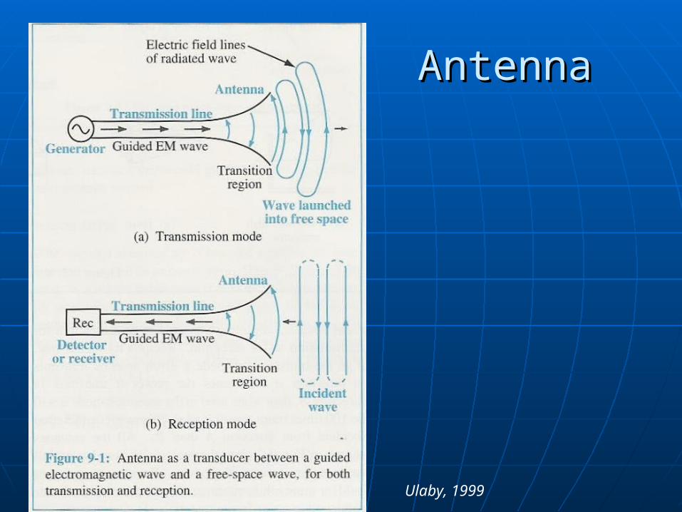
What is an antenna?What is an antenna?
An antenna is a An antenna is a passive structurepassive structure that that serves as transition between a serves as transition between a transmission linetransmission line and and airair used to used to transmit and/or receive electromagnetic transmit and/or receive electromagnetic waves. waves.
Source
Tx
Receiver Circuit
Rx
Antenna Antenna
Ulaby, 1999
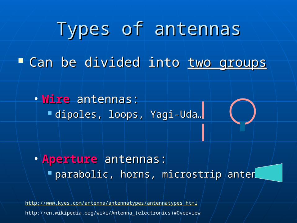
Types of antennasTypes of antennas
Can be divided into Can be divided into two groupstwo groups
• WireWire antennas: antennas: dipoles, loops, Yagi-Uda…dipoles, loops, Yagi-Uda…
• ApertureAperture antennas: antennas: parabolic, horns, microstrip antennas…parabolic, horns, microstrip antennas…
http://www.kyes.com/antenna/antennatypes/antennatypes.html
http://en.wikipedia.org/wiki/Antenna_(electronics)#Overview
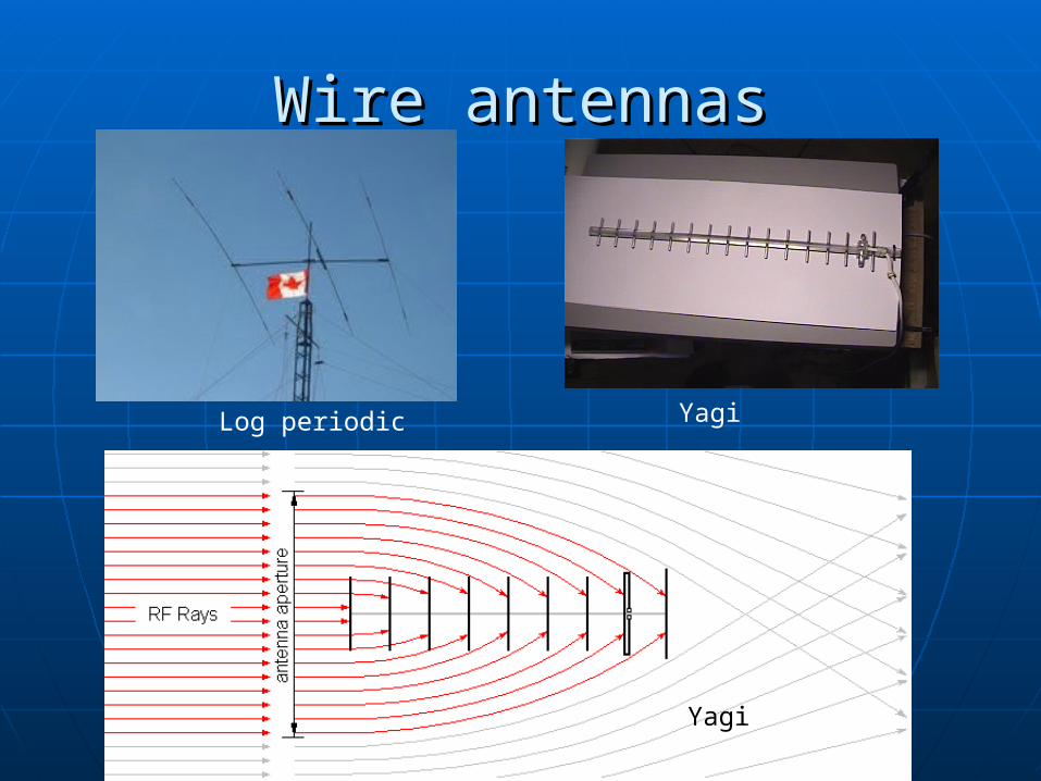
Wire antennasWire antennas
YagiLog periodic
Yagi
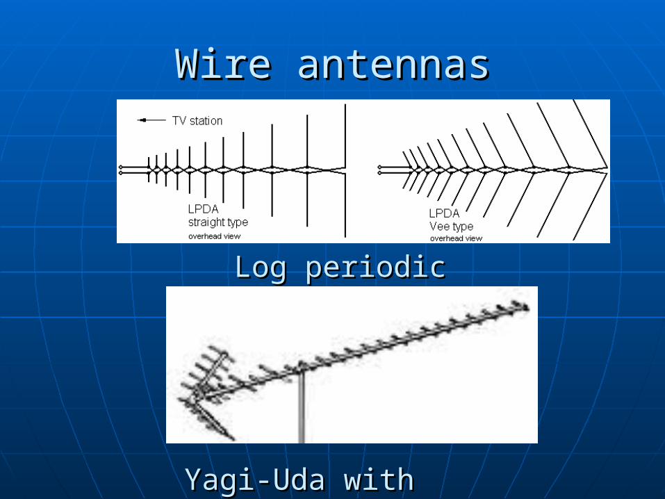
Wire antennasWire antennas
Log periodicLog periodic
Yagi-Uda with reflectorYagi-Uda with reflector

Aperture antennas Aperture antennas
Spherical (main reflector) with Gregorian feed
Dipole with parabolic and corner reflector

Reflector and Pyramidal horn Reflector and Pyramidal horn antennasantennas

Related parametersRelated parameters Solid angle, Solid angle, and Radiation intensity, and Radiation intensity, UU Radiation pattern, Radiation pattern, PPnn, sidelobes, HPBW, sidelobes, HPBW Far field zone, Far field zone, rrffff Directivity, Directivity, DD or Gain, or Gain, GG Antenna radiation impedance, Antenna radiation impedance, RRradrad Effective Area, Effective Area, AAee
All of these parameters are expressed in terms of a All of these parameters are expressed in terms of a transmissiontransmission antenna, but are identically antenna, but are identically applicable to a applicable to a receivingreceiving antenna. We’ll also antenna. We’ll also study: study:
Friis Transmission EquationFriis Transmission Equation Radar EquationRadar Equation

Spherical coordinatesSpherical coordinates
z (zenith)
x
y
= azimuth
= elevation =90=0
=0
=90=90

Solid AngleSolid Angle
s1 = r ds2 = r sin døs =r = arco dA = s1 s2
dA = r2 sin dø d = r2 dΩ
= ángulo plano dΩ = elemento de ángulo sólido•El arco total en un círculo: • El área total en una esfera:
= 2r = 4r2
•Angulo total: = 2 [radianes] •Angulo sólido total: =4 [rad2]=4 [sr]
1 steradian (sr) = (1 radian)2
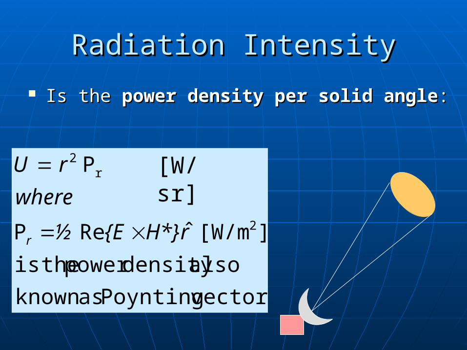
Radiation IntensityRadiation Intensity
Is the Is the power densitypower density per solid angleper solid angle::
vector.Poynting asknown
alsodensity power theis
][W/m ˆRe 2
r2
rH*E½
where
rU
r
P
P [W/sr]

Total radiated power by antennaTotal radiated power by antenna
Can be calculated as;Can be calculated as;
[W]
[W]
dSP
or
dUP
rrad
rad
P

Radiation PatternRadiation Pattern Radiation pattern is the Radiation pattern is the
3D plot of the gain, but 3D plot of the gain, but usually the two usually the two dimensional horizontal dimensional horizontal and and verticalvertical cross cross sections of the radiation sections of the radiation pattern are considered.pattern are considered.
Refers to the variation Refers to the variation of the relative of the relative amplitude of the amplitude of the radiation as a function radiation as a function of direction. of direction.
),(
),(
),(
),(),(
maxmax
U
UFn
PP
Field pattern:
Where U is the radiation intensity to be defined later.
),(
),(),(
max
E
EEn
Power pattern:

Total Total Solid AngleSolid Angle of an antenna of an antenna
z
y
x
žA
Patrón |P |n
[sr] ),(4
A dFn
A
Is as if you changed the radiation pattern beam of an antenna into a pencil beam shape and find out what’s the equivalent solid angle occupied by this pattern.

Isotropic antennaIsotropic antenna It’s an It’s an hypothetic antennahypothetic antenna, ,
i.e., it does not exist in real i.e., it does not exist in real life, yet it’s used as a life, yet it’s used as a measuring bar for real measuring bar for real antenna characteristics. antenna characteristics.
It’s a point source that It’s a point source that occupies a negligible space. occupies a negligible space. Has no directional preference. Has no directional preference.
Its pattern is simply a Its pattern is simply a spheresphere so it has so it has AA= = isotropicisotropic= = 44steradianssteradians..
4sin)1(
)1(
0
2
0
4
isotropic
dd
d
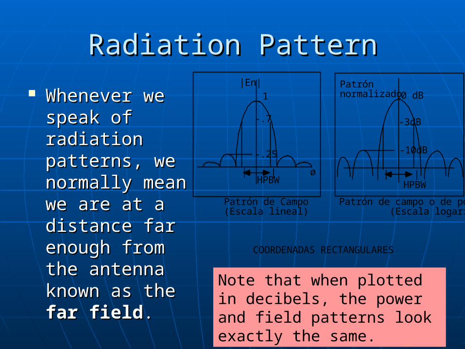
Radiation PatternRadiation Pattern
Whenever we Whenever we speak of speak of radiation radiation patterns, we patterns, we normally mean normally mean we are at a we are at a distance far distance far enough from enough from the antenna the antenna known as the known as the far fieldfar field..
_ 1
HPBWø
-.25
-.7
|En|
- 0 dB
-3dB
-10dB
| | | |HPBW
Patrón de campo o de potencia (Escala logarítmica)
Patrón de Campo (Escala lineal)
COORDENADAS RECTANGULARES
Patrón normalizado
Note that when plotted in decibels, the power and field patterns look exactly the same.

Pattern – polar plotPattern – polar plot
Lóbulo principal
.5
1
HPBW
Lóbulos menores
NNBW
("Mainlobe")
|Pn|
PATRON TIPICO (Coordenadas polares esféricas, 2 dimensiones)

Dipole antenna patternDipole antenna pattern
Note the radiation pattern is donut shaped.
SidelobesSidelobes
Antennas sometimes show Antennas sometimes show side lobesside lobes in in the radiation pattern. the radiation pattern.
Side lobes are peaks in gain other than the Side lobes are peaks in gain other than the main lobe (the "beam").main lobe (the "beam").
Side lobes have bad impact to the Side lobes have bad impact to the antenna quality whenever the system is antenna quality whenever the system is being used to determine the being used to determine the direction of a of a signal, for example in signal, for example in RADAR systems. systems.

Sidelobes of dipole arraysSidelobes of dipole arrays
sidelobe

Antenna Pattern with sidelobesAntenna Pattern with sidelobes
Many applications require sidelobe levels (SLL) to be below -20dB.
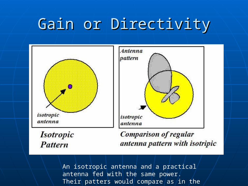
Gain or DirectivityGain or Directivity
An isotropic antenna and a practical antenna fed with the same power. Their patters would compare as in the figure on the right.

Directivity and GainDirectivity and Gain
All practical antennas radiate more than the All practical antennas radiate more than the isotropic antenna in some directions and less in isotropic antenna in some directions and less in others.others.
Gain is inherently directional; the gain of an Gain is inherently directional; the gain of an antenna is antenna is usually measured in the usually measured in the direction which it radiates bestdirection which it radiates best. .
aveave /UUDD maxmaxmax /),( PP
If lossless antenna, G=D

Gain or DirectivityGain or Directivity
Gain is measured by comparing an Gain is measured by comparing an antenna to a model antenna, antenna to a model antenna, typically the typically the isotropic antenna which which radiates equally in all directions. radiates equally in all directions.
pn dF
rD
4
,
4),(
4
2
/ Aisotropic oD

Directivity Directivity For an antenna with a single main lobe For an antenna with a single main lobe
pointing in the z-direction , pointing in the z-direction , AA can be can be approximated to the product of the HPBWapproximated to the product of the HPBW
eyzxz
yzxzA
AD
then
2A
4 4 /4
The Directivity:

Far fieldFar field
The distance at which the fields The distance at which the fields transmitted by an antenna (spherical) transmitted by an antenna (spherical) can be approximated to plane waves. can be approximated to plane waves.
It’s defined asIt’s defined as
/2 2Drff D = is the largest physical dimension of the antenna = wavelength of operationrff = distance from the antenna to the observation point

Beamwidth, HPBWBeamwidth, HPBW
Is the “distance” in radians o degrees Is the “distance” in radians o degrees between the direction of the between the direction of the radiation pattern where the radiated radiation pattern where the radiated power is half of the maximum.power is half of the maximum.
DHPBM
dB - .
dB - .
o 70
shape; beam" pencil"for
37070log20
350log10

Antenna ImpedanceAntenna Impedance An antenna is “seen" by the generator as a load with An antenna is “seen" by the generator as a load with
impedance impedance ZZA A ,, connected to the line. connected to the line.
The real part is the radiation resistance plus the The real part is the radiation resistance plus the ohmic resistanceohmic resistance..• Minimizing impedance differencesMinimizing impedance differences at each interface will at each interface will
reduce SWRreduce SWR and and maximize power transfermaximize power transfer through each part through each part of the antenna system.of the antenna system.
• Complex impedance, Complex impedance, ZZA A ,, of an antenna is related to the of an antenna is related to the electrical length of the antenna at the wavelength in use. electrical length of the antenna at the wavelength in use.
The impedance of an antenna can be matched to the feed line The impedance of an antenna can be matched to the feed line and radio by adjusting the impedance of the feed line, using the and radio by adjusting the impedance of the feed line, using the feed line as an impedance feed line as an impedance transformer. .
More commonly, the impedance is adjusted at the load (see More commonly, the impedance is adjusted at the load (see below) with an antenna tuner, a balun, a matching transformer, below) with an antenna tuner, a balun, a matching transformer, matching networks composed of inductors and capacitors, or matching networks composed of inductors and capacitors, or matching sections such as the gamma match.matching sections such as the gamma match.
ALradA jXRRZ ZA
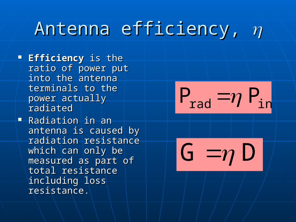
Antenna efficiency, Antenna efficiency, EfficiencyEfficiency is the ratio is the ratio
of power put into the of power put into the antenna terminals to antenna terminals to the power actually the power actually radiated radiated
Radiation in an Radiation in an antenna is caused by antenna is caused by radiation resistance radiation resistance which can only be which can only be measured as part of measured as part of total resistance total resistance including loss including loss resistance. resistance.
in rad P P
D G

Radiation ResistanceRadiation Resistance
The antenna is connected to a T.L., and The antenna is connected to a T.L., and it “sees” it as an impedance.it “sees” it as an impedance.
The power radiated is The power radiated is
The loss power isThe loss power is
loss rad
rad
loss rad
rad
R
R
PP
P
R
rad2o rad RI
2
1 P
L2o loss RI
2
1 P

Radar equationRadar equation What is a radar?What is a radar?
Received power by a radar from a single target Received power by a radar from a single target isis
Where Where is the backscattering coefficient of is the backscattering coefficient of the target [mthe target [m22]]
2
43
22
4 e
R
GPP oot
r

Antenna polarizationAntenna polarization
The The polarizationpolarization of an antenna is the of an antenna is the polarization of the signals it emits. polarization of the signals it emits. • The ionosphere changes the polarization of The ionosphere changes the polarization of
signals unpredictably, so for signals which will signals unpredictably, so for signals which will be reflected by the ionosphere, polarization is be reflected by the ionosphere, polarization is not crucial. not crucial.
• However, for line-of-sight communications, it However, for line-of-sight communications, it can make a tremendous difference in signal can make a tremendous difference in signal quality to have the transmitter and receiver quality to have the transmitter and receiver using the same polarization. using the same polarization.
• Polarizations commonly considered are Polarizations commonly considered are verticalvertical, , horizontalhorizontal, and , and circularcircular..

Antenna BandwidthAntenna Bandwidth The The bandwidthbandwidth of an antenna is the range of of an antenna is the range of
frequencies over which it is effective, usually frequencies over which it is effective, usually centered around the operating or resonant centered around the operating or resonant frequency. frequency.
• The bandwidth of an antenna may be increased by The bandwidth of an antenna may be increased by several techniques, including using thicker wires, several techniques, including using thicker wires, replacing wires with replacing wires with cagescages to simulate a thicker wire, to simulate a thicker wire, tapering antenna components (like in a feed horn), and tapering antenna components (like in a feed horn), and combining multiple antennas into a single assembly and combining multiple antennas into a single assembly and allowing the natural impedance to select the correct allowing the natural impedance to select the correct antenna.antenna.

Effective AreaEffective Area
How a Rx antenna extracts energy How a Rx antenna extracts energy from incident wave and delivers it to from incident wave and delivers it to a load?a load?
Above is valid for any antenna under Above is valid for any antenna under matched-load conditionsmatched-load conditions
4
P 2
inc
rec DAe
P
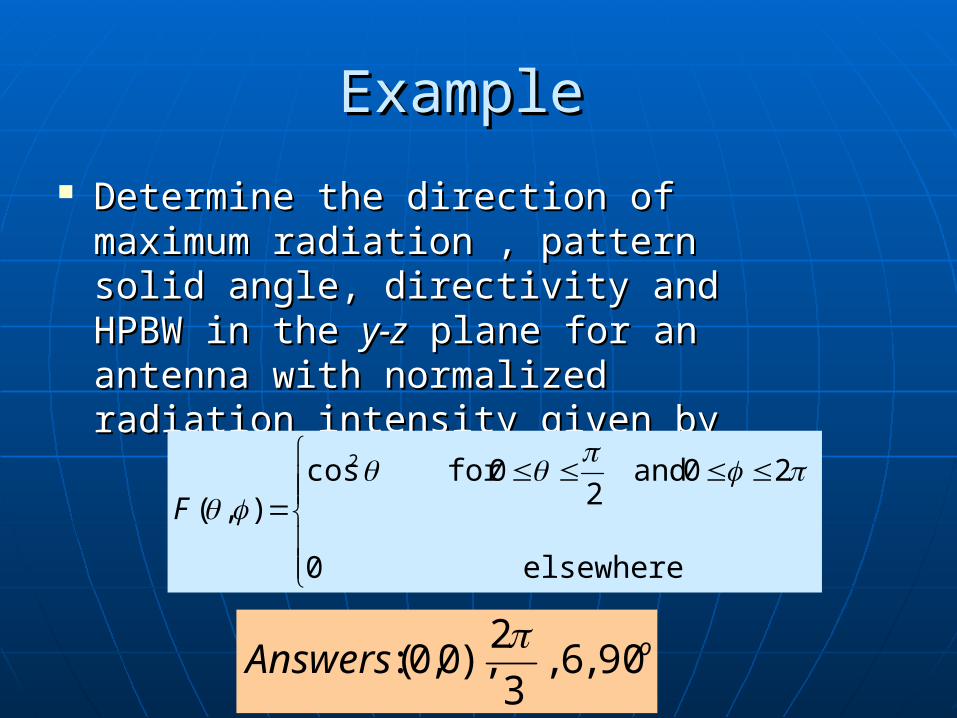
Example Example
Determine the direction of maximum Determine the direction of maximum radiation , pattern solid angle, radiation , pattern solid angle, directivity and HPBW in the directivity and HPBW in the y-zy-z plane plane for an antenna with normalized for an antenna with normalized radiation intensity given by radiation intensity given by
elsewhere 0
20 and 2
0for cos),(
2
F
oAnswers 90,6,3
2),0,0(:

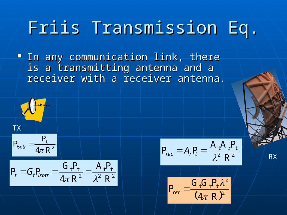
Friis Transmission Eq.Friis Transmission Eq.
In any communication link, there is In any communication link, there is a transmitting antenna and a a transmitting antenna and a receiver with a receiver antenna.receiver with a receiver antenna.
2t
R4
P
isotrP
22t t
2t t
R
PA
R4
PG
isotrtt G PP
22t rt
R
PAA
trrec A PP
2t rt
R4
PGG 2
recP
TX
RX
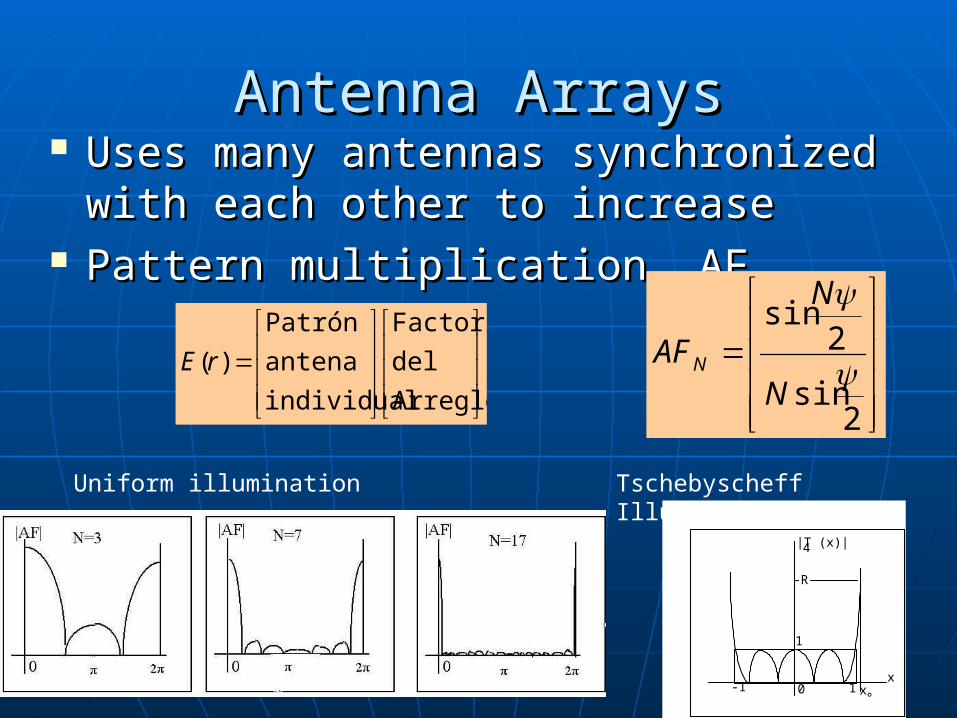
Antenna ArraysAntenna Arrays Uses many antennas synchronized Uses many antennas synchronized
with each other to increasewith each other to increase Pattern multiplication, AFPattern multiplication, AF
Arreglo
del
Factor
individual
antena
Patrón
)(rE
2sin
2sin
N
N
AFN
1
-1 1x
|T (x)|4
-R
x0°
Uniform illumination Tschebyscheff Illumination
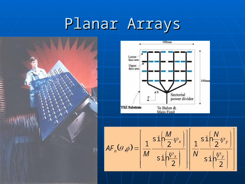
Planar ArraysPlanar Arrays