introduction - timberpro inctimberpro.com/operator/820dops/ops1.pdf · figure 2: general...
TRANSCRIPT

Introduction0.1Form M247
Introduction
TIMBCO TF800 Hydro-Skidder
“Built By LoggersFor Loggers”
TIMBCO, Inc.
Shawano, WI
00382

Introduction 0.2
IntroductionThe purpose of this manual is to familiarize the newowner/operator with the many features of theTIMBTEC TF800 Hydro-Skidder so that they maybecome proficient in the machine’s operation andperiodic maintenance. This manual is provided withdetailed operating and maintenance instructions aswell as safety information and equipment data.
Throughout this manual, references are made to thefront, rear, left and right sides of the machine.Determine front, rear left and right when sitting inthe operator’s seat and looking out over the fueltank.
The instructions and procedures in this manualcover the basic machine model furnished with themost commonly used options. Pictorial informationin some areas may vary slightly from the actualmachine on hand. This variation, however, does nothave any impact on the accuracy of the writteninformation.
The information contained in this manual is currentat the time of publication, however, continuingproduct improvement may result in changes to themachine which are not covered. Should you requireinformation regarding such changes or any otherinformation on the machine, please contact yourTIMBTEC dealer.
Form M247
Figure 1: Directional Reference (Shown in forwarder configuration)
Rear
Left Right
Front
Fuel Tank

Introduction0.3
TIMBTECNomenclature - TF800 Forwarder
Form M247
Figure 2: General Nomenclature - TF800 Short Wood Forwarder
Hydraulic Oil Tank
LogRack
LogStake (8)
Operator’s Cab(ROPS/FOPS/OPS)
Main Boom
LoaderBucket
StickBoom
FloatingBunk
Engine CompartmentEmergency
Escape Hatch
Frame ArticulationBearing & Joint
(2) N.A.F. Tandem Double Bogie Axle(Several Tire Combinations Available)
FuelTank
(2) SteerCylinder
CaliperBrake

Introduction 0.4 Form M247
TIMBTECNomenclature - TF800 Clam Bunk Skidder
Figure 3: General Nomenclature - TF800 Clam Bunk Skidder
Hydraulic Oil Tank
ClamBunk
CaliperBrake
ClamBunk
Operator’s Cab(ROPS/FOPS/OPS)
Main Boom
LoaderBucket
StickBoom
Engine Compartment
EmergencyEscape Hatch
Frame ArticulationBearing & Joint
(2) N.A.F. Tandem Double Bogie Axle(Several Tire Combinations Available)
(2) SteerCylinder
FuelTank

Introduction0.5Form M247
Figure 4: Upper Turntable Nomenclature - Side View (Less Cab and Booms)
Return Filter Guard (Removed)
00017
Radiator Fill Spout Access Cover (Open)
00016
Louvered Swing-Out Radiator Guard (Open)
00022
Slotted Engine Pivot Guard (Open)
00021
HydraulicOil Tank
Air Cleaner/ Muffler Area
Engine CompartmentROPS Panel
Swing Bearing
SwingMotor
ContinuousRotation Swivel

Introduction 0.6 Form M247
Figure 5: Upper Turntable Nomenclature - End View (Less Cab and Booms)
Perforated Swing-Out Engine Guard (Open)
00001
Main BoomPivot Point
HydraulicOil Tank
SwingMotor
Engine CompartmentROPS Panel
Swing Bearing
Boom SidePump Panel
Upper TurntableBase Plate
Swing-Out Pump Access Guard (Open)
00279
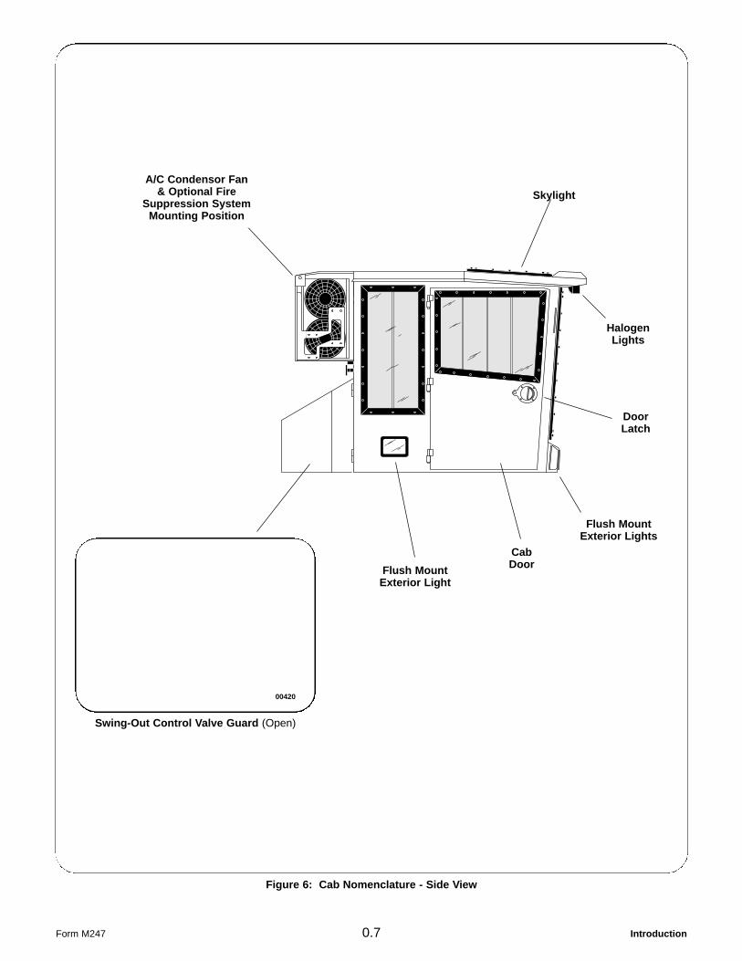
Figure 6: Cab Nomenclature - Side View
Introduction0.7Form M247
Skylight
DoorLatch
HalogenLights
Flush MountExterior Lights
CabDoorFlush Mount
Exterior Light
A/C Condensor Fan& Optional Fire
Suppression SystemMounting Position
Swing-Out Control Valve Guard (Open)
00420
Introduction 0.8 Form M247
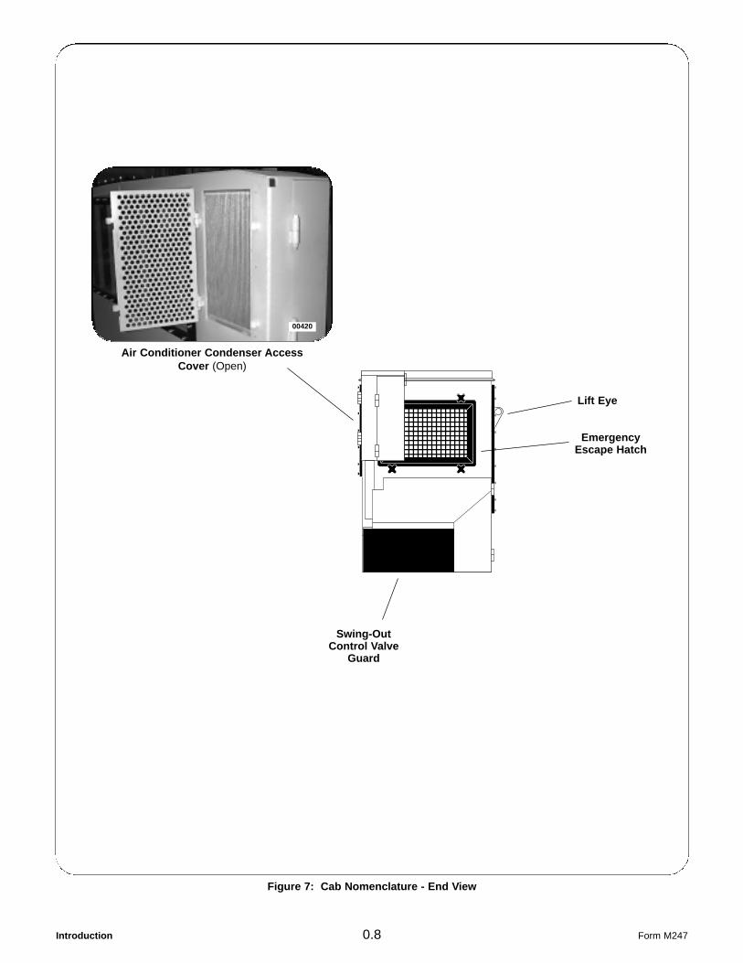
Figure 7: Cab Nomenclature - End View
Lift Eye
Air Conditioner Condenser AccessCover (Open)
00420
EmergencyEscape Hatch
Swing-OutControl Valve
Guard

Introduction0.9Form M247
Figure 8: Loader Boom Nomenclature
Main Boom
Boom ElbowPivot
Stick BoomCylinder
Main BoomTubelines
Main BoomCylinder
StickBoom
Loader Bucket(Hultdins Supergrip 360S Shown)
Main BoomPivot Point
StickBoom
Tubelines

Introduction 0.10 Form M247
Figure 9: Front Frame Nomenclature
Swing BearingMountingSurface
N.A.F. TandemBogie Axle
(2) 28L-26Tires
Transfer Case & Drive Motor AccessCovers (Open)
00436
FrameArticulation
BearingMountingSurface
FuelTank

Introduction0.11Form M247
Figure 11: Rear Frame Nomenclature
Differential & Upper Brake AccessCover (Open)
00432
Drive Shaft, Steer Cylinder & Steer BoxAccess Covers (Open)
00433
FloatingBunk
RearFrame
N.A.F. TandemBogie Axle
(2) 28L-26Tires
Introduction 0.12 Form M247
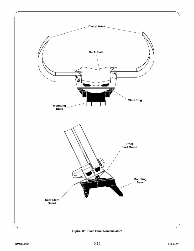
Figure 12: Clam Bunk Nomenclature
Clamp Arms
Deck Plate
FrontSkirt Guard
Slew Ring
MountingBase
MountingBase
Rear SkirtGuard

Introduction0.13Form M247
Important Model& Serial NumbersFor quick reference, use the lines provided beloweach illustration to record important manufacturer,model and serial number information for yourTIMBTEC Hydro-Skidder and its majorcomponents. These serial numbers will allow yourTIMBTEC dealer to correctly identify your machineand its components when filling replacement partsorders or providing service information.
Engine (Typical)
Manufacturer__________________________________
Model_____________________________________
S/N#______________________________________
TIMBTEC Hydro-Skidder
Model__________
S/N#______________________________________
Tandem Bogie Axles
Manufacturer__________________________________
FRONT:
Model__________
S/N#______________________________________
REAR:
Model__________
S/N#______________________________________
00007
00386
00408
Transfer Case (Typical)
Model__________
S/N#______________________________________
00283
Wheel Drive Pump(May be installed with the SN# tag on bottom face)
Manufacturer__________________________________
Model_____________________________________
S/N#______________________________________
00281

Introduction 0.14 Form M247
Swing Motor
Manufacturer__________________________________
Model_____________________________________
S/N#______________________________________
00024
Loader Bucket
Manufacturer__________________________________
Model_____________________________________
S/N#______________________________________
Loader Pump(Installed with the SN# tag on bottom face)
Manufacturer__________________________________
Model_____________________________________
S/N#______________________________________
00032
Wheel Drive Motor(Installed with the SN# tag on bottom face)
Manufacturer__________________________________
FRONT:
Model__________
S/N#______________________________________
REAR:
Model__________
S/N#______________________________________
00282
00280
Loader Bucket Rotator
Manufacturer__________________________________
Model_____________________________________
S/N#______________________________________
00280

Introduction0.15Form M247
Clam Bunk
Manufacturer__________________________________
Model_____________________________________
S/N#______________________________________
00284

Introduction 0.16 Form M247
THIS PAGE LEFT BLANK FOR NOTES

Safety - General Information1.1.1Form M004
Section 1.1
Safety -General Safety Information
General . . . . . . . . . . . . . . . . . . . . . . . . . . . . . . . . . . . . . . . . . . . . . . . 1.1.2
“Safety Alert” Symbol . . . . . . . . . . . . . . . . . . . . . . . . . . . . . . . . . . . . 1.1.2
Understanding Signal Words . . . . . . . . . . . . . . . . . . . . . . . . . . . . . . . 1.1.2
The Careful Operator . . . . . . . . . . . . . . . . . . . . . . . . . . . . . . . . . . . . 1.1.3

Safety - General Information 1.1.2
GeneralTIMBCO’s policy is to produce products that aresafe and reliable. However, even when using wellengineered equipment, there will always be anelement of risk in heavy equipment operation.
Most accidents involving heavy equipmentoperation, maintenance or service result fromfailure to follow basic safety rules and precautions.To minimize the risks and promote safety at alltimes, the safety group in this manual details anumber of safety rules which should always befollowed and obeyed.
Study all the safety messages carefully, rememberthem and apply them when operating, maintainingor servicing this machine.
“Safety Alert” Symbol
The “Safety Alert” symbol is used where applicablethroughout the text and on the machine toindicate important personal safety measures andequipment cautions. Carefully read, understandand follow these instructions to prevent hazardoussituations, possible injuries to personnel or damageto the machine.
Understanding Signal WordsIn this manual and on the safety decals installed onthe machine, the “Safety Alert” symbol is alwaysaccompanied by a signal word to identify the hazardleve. Understand the signal words DANGER,WARNING, and CAUTION.
Identifies the most serious safety hazardswhere failure to follow the safety messagewould result in high probability of death orserious personal injury.
Identifies that a safety hazard exists wherefailure to follow the safety message canresult in death or serious personal injury ifproper precautions are not taken.
Identifies that a hazard exists where failureto follow the safety message can result inpersonal injury or equipment damage if theproper precautions are not taken.
The signal words DANGER, WARNING andCAUTION are used to identify personal safetyhazards and some equipment cautions. In thismanual, the signal word NOTICE is also used toidentify hazards that may damage the machine orits components.
Follow procedures outlined to avoid damage tothe machine or its components as a result ofuse or improper procedures.
Form M004
DANGER
WARNING
CAUTION
NOTICE
Figure 1 - Safety Alert Symbol

Safety - General Information1.1.3
The Careful OperatorThe careful operator is one who studies,remembers and applies the basic safety rules andall safety messages found in the manuals and onthe equipment being operated, maintained orserviced. This person also has the requiredtraining, skills and tools to operate this machineand/or perform the required maintenance andservice procedures.
TIMBCO cannot anticipate every possiblecircumstance where a potential hazard may exist.Therefore, the safety messages and equipmentcautions found in this manual and on themachine are not all inclusive. If an operatingtechnique, maintenance or service procedure, tool,etc... not specifically recommended by TIMBCO isused, it is your responsibility to insure it is safe foryourself and others. You should also be sure themachine will not be damaged or made unsafe by theoperation, maintenance procedures or serviceprocedures you choose.
WHEN IT COMES TO SAFETY, NOTHING WILLEVER REPLACE A CAREFUL OPERATOR.
Form M004
SAFETY FIRST !

Safety - General Information Form M004
THIS PAGE LEFT BLANK FOR NOTES

Safety - Safety Decals Installed On Machine1.2.1Form M185
Section 1.2
Safety -Safety Decals Installed On Machine
General . . . . . . . . . . . . . . . . . . . . . . . . . . . . . . . . . . . . . . . . . . . . . . . 1.2.2
Emergency Escape Markers . . . . . . . . . . . . . . . . . . . . . . . . . . . . . . . 1.2.4

Safety - Safety Decals Installed On Machine 1.2.2
GeneralThere are a number of specific safety decalsinstalled on the machine. The location and safetymessage of each is reviewed here. Study andremember the locations of all safety messages.
All safety and equipment caution decals should bekept clean and readable. Clean decals with a milddetergent and water only. Never use solvents toclean decals or damage to the decal will result.
For your own safety and the safety of others it isyour responsibility to replace any missing,damaged or otherwise unreadable safety orequipment caution decals. If a component with adecal is replaced, be sure a new decal is installed.
CRUSH ZONE. Keep clear to avoidpersonal injury or death.
The hydraulic tank is under pressure.
Vent tank before removing fill cap orSerious personal injury could result.
When fueling, servicing or repairing, setbooms on ground and shut down engine.
Never operate the machine without thedoor closed and seat belt fastened.
QUALIFIED OPERATORS ONLY. StudyOperator’s Manual. Injury or death canresult from untrained operation.
Form M185
Located on left side of cab weldment near swing motor(shown), at all pivot points of the frame and, when
equipped, at all cab leveling component pivots.
Located on upper left horizontal member inside the cabDANGER
WARNING
Located on hydraulic tank fill spout guard
00023
00383
WARNING
00019

Safety - Safety Decals Installed On Machine1.2.3
Use of this ROPS in a damaged, modifiedor abused condition or with prior overturnis unsafe and the operator protection is nolonger suitable and must be replaced.Any alterations, modifications, add-onsor repair without the written consent ofTIMBCO HYDRAULICS, INC. will void theproduct’s warranty, liability andcertification.
Fan guard must be bolted in place beforeoperating unit.
Keep clear of all moving parts. Seriouspersonal injury could result.
Do not remove the tank support with thehydraulic tank installed.
If the tank support must be swung out ofthe way, be sure the hydraulic tank issupported by other means.
Serious personal injury or damage to theequipment could result.
Form M185
Located on upper rear horizontal member inside the cab
00466
WARNING
Located in several places around engine fan shroud
00287
WARNING
Located on the side of the hydraulic tank near the boom
00285
CAUTION
Located in several places around engine fan shroud
00287
CAUTION
Safety - Safety Decals Installed On Machine 1.2.4 Form M185
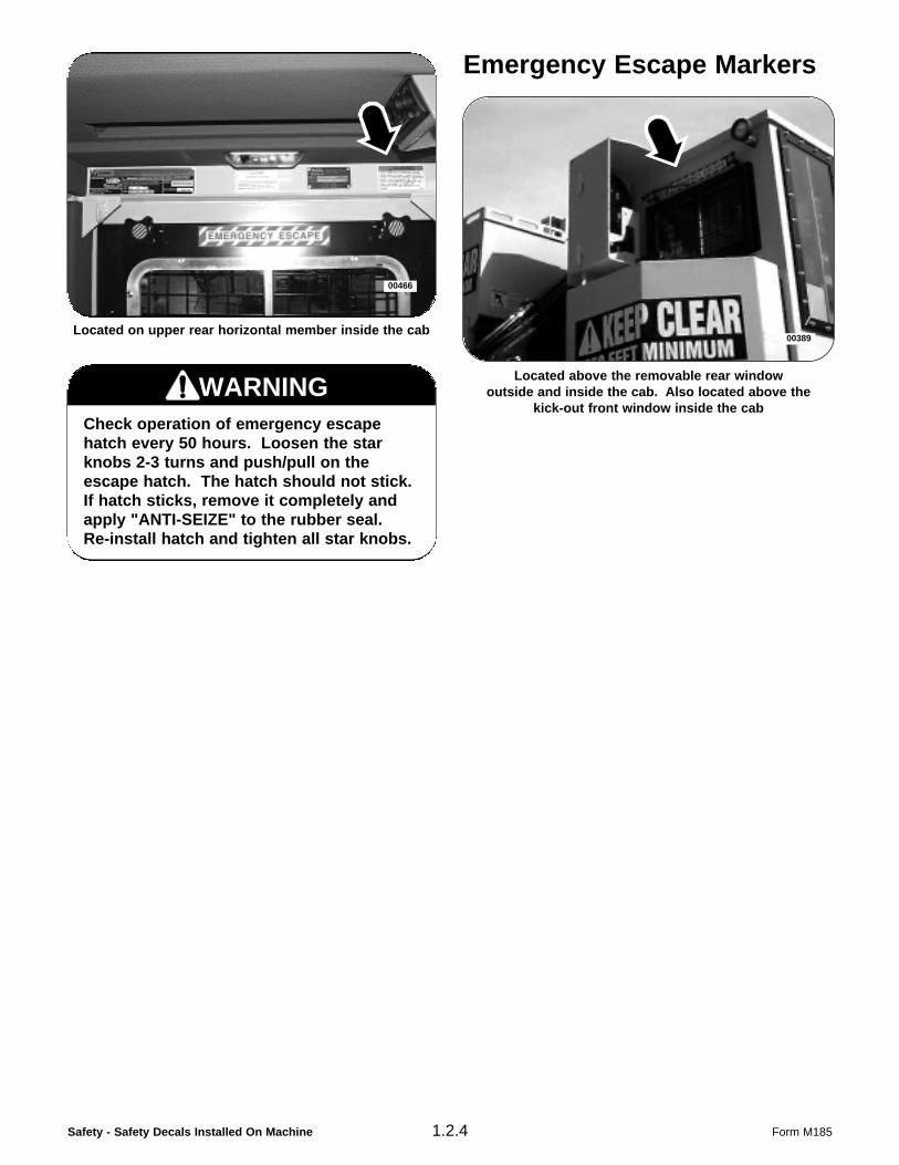
Check operation of emergency escapehatch every 50 hours. Loosen the starknobs 2-3 turns and push/pull on theescape hatch. The hatch should not stick.If hatch sticks, remove it completely andapply "ANTI-SEIZE" to the rubber seal.Re-install hatch and tighten all star knobs.
Emergency Escape Markers
Located above the removable rear windowoutside and inside the cab. Also located above the
kick-out front window inside the cab
00389Located on upper rear horizontal member inside the cab
00466
WARNING

Safety - Basic Safety Rules & Precautions1.3.1Form M251
Section 1.3
Safety - Basic Safety Rules & Precautions
Personal Precautions . . . . . . . . . . . . . . . . . . . . . . . . . . . . . . . . . . . . 1.3.2
General Operator Precautions . . . . . . . . . . . . . . . . . . . . . . . . . . . . . . 1.3.2
Mounting And Dismounting Precautions . . . . . . . . . . . . . . . . . . . . . . 1.3.3
Operation Precautions:General . . . . . . . . . . . . . . . . . . . . . . . . . . . . . . . . . . . . . . . . . . . . 1.3.3Before Starting Engine . . . . . . . . . . . . . . . . . . . . . . . . . . . . . . . . . 1.3.3Before Beginning To Work . . . . . . . . . . . . . . . . . . . . . . . . . . . . . . 1.3.4During Machine Operation . . . . . . . . . . . . . . . . . . . . . . . . . . . . . . 1.3.4Parking The Machine . . . . . . . . . . . . . . . . . . . . . . . . . . . . . . . . . . 1.3.5
Service And Maintenance Precautions:General . . . . . . . . . . . . . . . . . . . . . . . . . . . . . . . . . . . . . . . . . . . . 1.3.5Towing The Machine . . . . . . . . . . . . . . . . . . . . . . . . . . . . . . . . . . 1.3.7Cooling And Hydraulic System . . . . . . . . . . . . . . . . . . . . . . . . . . . 1.3.7Fluid Penetration . . . . . . . . . . . . . . . . . . . . . . . . . . . . . . . . . . . . . 1.3.8Diesel Fuel . . . . . . . . . . . . . . . . . . . . . . . . . . . . . . . . . . . . . . . . . 1.3.8Batteries . . . . . . . . . . . . . . . . . . . . . . . . . . . . . . . . . . . . . . . . . . . 1.3.9Ether Starting Aid (Optional) . . . . . . . . . . . . . . . . . . . . . . . . . . . . . 1.3.10Asbestos Information . . . . . . . . . . . . . . . . . . . . . . . . . . . . . . . . . . 1.3.11

Safety - Basic Safety Rules & Precautions 1.3.2
Personal Precautions
Avoid loose fitting clothing, loose or uncovered longhair, jewelry and loose personal articles.
Do not rush. Walk, do not run.
Use only approved signaling practices. Only acceptsignals from one designated person.
General Operator PrecautionsCarry no passengers. The machine is provided andapproved with seating for the operator only.
Keep floors, steps and running boards clean andfree of oil, ice, mud and loose objects.
Properly secure all loose items not part of themachine such as tools, maintenance items, andlunch boxes.
Inspect the machine daily for signs of damage,unusual wear, fluid leaks or faulty operation.
Clean out debris from high heat areas, such as theengine compartment, frequently during the workingshift and always after quitting operations for the day.
Never remove any element of the engine’s exhaustsystem or any safety covers or devices from theoperational machine.
Get to know the capabilities and limitations of themachine and learn the most efficient operating techniques.
Form M251
Use recommended protective clothing and safetydevices such as gloves, safety boots, safety hat,reflective vests and eye, ear and respiratoryprotection as required by job conditions.
00008
Comply with the instructions in this manual andyour company’s regulations for the operation ofthis machine.
YOU MUST BE FULLY TRAINED to operate thismachine and its felling attachment.
00007
Keep a comprehensive and complete first aid kitin an easily accessible place on the machine atall times.
00010
Maintain a charged fire extinguisher on themachine AND KNOW HOW TO USE IT.
00027

Safety - Basic Safety Rules & Precautions1.3.3
Mounting And DismountingPrecautionsUse tread plates and handles provided with at leastthree points of support (two hands and one foot ortwo feet and one hand) when mounting anddismounting the machine. Do not climb, mount ordismount machine in any other fashion.
Always face machine when mounting anddismounting.
NEVER attempt to mount or dismount a movingmachine.
NEVER jump from the machine.
Do not use the controls or operator’s seat armrestas a handhold when mounting or dismounting themachine.
Do not carry tools or other materials with you as youmount or dismount the machine. Get assistance oruse a hand line to raise and lower materials.
Operation Precautions
General
Operate the machine controls only from a seatedposition in the operator’s seat.
Operate the machine only when physically fit andnot under the influence of alcohol or drugs.
EMERGENCY ESCAPE: An emergency escape isprovided on all TIMBTEC Hydro-Skidders. SeeSection 2.2 for additional information.
Report all required repairs.
Before Starting Engine
Be sure no one is working on, underneath or closeto the machine. KEEP ALL PERSONNEL CLEAR.
Check the machine to insure that all doors, panels,and access covers are installed and properlysecured.
Start machine ONLY from the operator’s seat.Never short across the starter terminals orbatteries.
Adjust the operator’s seat correctly. Full foot pedaltravel must be obtained with your back firmlyagainst the seat back.
If working conditions require lighting, be suremachine is adequately equipped with lighting andthat it is in good working condition.
When ready to start engine, be sure all controls arepositioned as specified in the engine startinginstructions in Section 4.1.
When the engine is running, allow no personnel inthe areas of the machine where they may becrushed by moving components.
Form M251
Diesel exhaust fumes contain elements that arehazardous to your health. Always run engine in awell ventilated area. If in an enclosed space,vent exhaust to the outside.
00015
The operator’s seat is equipped with a seat belt.Use this belt at all times when operating themachine.
00014

Safety - Basic Safety Rules & Precautions 1.3.4
Before Beginning To Work
Fasten safety belt.
Always allow for adequate warm-up of the engineand hydraulic oil, particularly when ambienttemperature is below 32oF (0oC). Refer to coldweather starting instructions in Section 4.1.
Check operation of emergency escapehatch every 50 hours. See Section 5.3 forprocedures.
Check all controls for proper operation. If a controlis malfunctioning, stop immediately and have theproblem corrected before resuming work.
Be aware of all obstacles and hazards around you;stumps, slopes, ditches, overhead wires, etc.
Before moving the machine, check position of framearticulation joint. Normal forward travel is with theframe articulation joint behind the cab. When theframe articulation joint is in front of the cab thereverse steer feature, see Section 3.3, should beactivated otherwise the steering controls must beworked opposite.
During Machine Operation
Adhere strictly to all regulations at the work sitepertaining to the operation of this machine.
Know the capacities and limitations of the machineand DO NOT exceed them. Lift capacity decreasesas the load moves away from the machine.
If a failure occurs that causes the loss of implementcontrol, steering, brakes or engine, stop machinemotion as quickly as possible, lower the grapple tothe ground and shut down machine. Leavemachine parked until repairs can be made or themachine can be towed.
Keep eye contact on the grapple and itsimmediate surroundings at all times when handlingthe load.
Maintain a safe operating distance between themachine and other equipment and personnel.
NEVER swing the boom or grapple above theheads of bystanders.
When moving the machine, watch that enoughclearance is available on both sides and abovethe boom. Extra clearance may be requiredparticularly where ground is uneven.
Maintain a safe operation distance from hazardssuch as steep drop-offs, deep ditches and areaswhere the ground may be unstable and allow themachine to slide or tip.
Drive machine with care and at speeds compatiblewith job conditions. Use extra care on roughground, slopes and when turning the machine.
Approach an area where overhanging electricalpower lines are present with EXTREME CAUTION.Serious injury or death by electrocution could resultif the machine or its grapple is not kept a safedistance away from these lines. Keep machine andbooms at least 10 ft. (3m), plus an additional 1/2”(10mm) for each 1,000 volts over 50,000 volts, fromany power line. If state/province, local or job siteregulations require even greater safetydistances than stated above, adhere strictly to thoseregulations for your protection.
Keep grapple close to ground level, approximately15” (40 cm), while traveling.
Keep loads close to the machine when traveling orswinging and avoid conditions and operatingpractices that may lead to tipping or overturning themachine.
On steep slopes, travel as straight up and down aspossible and always carry any load on the uphillside of the machine.
Always lower the booms so that the grapple rests onthe ground whenever operation is stopped;regardless if the engine is running or not.
Use a recommended vehicle when transporting themachine between jobsites.
When transport of machine is required, make surethat it is adequately secured to the vehicle. Eventhough the machine’s parking brakes are fullyengaged, block the wheels to prevent movementduring transport.
Form M251
WARNING

Safety - Basic Safety Rules & Precautions1.3.5
When transporting the machine, know and use thesignaling devices required by the machine. Provide an escort for transporting the machinewhen required.
Parking The Machine
When parking the machine, select a spot where theground is level. Do not park on a hillside or anincline.
When in freezing conditions, planks can be placedunder the machine to prevent the wheels fromfreezing into the ground.
Lower grapple to the ground and shut down theengine. Remove ignition key and place insafekeeping.
If the machine is to be parked for a greater length oftime, such as overnight, switch off the masterelectrical disconnect or disconnect the positive(+) battery cable.
Service And MaintenancePrecautionsGeneral
Unless otherwise specified, all maintenance orrepair procedures should begin as follows:
1) Position machine on level ground.2) Lower grapple to the ground.3) Shut down engine. Remove ignition key
and place in safekeeping.4) Switch off master electrical disconnect or
disconnect the positive (+) battery cable.
Run the engine only when it is required for test oradjustment purposes.s
Form M251
Diesel exhaust fumes contain elements that arehazardous to your health. Always run engine in awell ventilated area. If in an enclosed space,vent exhaust to the outside.
00015
Before performing maintenance or repairs on themachine, consult this manual and follow therecommended procedures.
00019
Keep your head, hands, and feet clear of allmoving parts.
00016
Keep yourself, all objects and tools away frommoving fan blades. Fan blades will cut or throwany object dropped or pushed into them.
00020

Safety - Basic Safety Rules & Precautions 1.3.6
Always use the proper tools for the job. Repair orreplace any broken or damaged tools, includinglifting equipment, immediately.
When servicing or replacing hardened steel pins,use a brass drift or other suitable material betweenthe hammer and pin if it must be driven into thepivot. Use safety glasses or other suitable eyeprotection.
DO NOT make adjustments while the machine ismoving or the engine is running unless otherwisespecified to do so.
DO NOT change the pressure setting on anyhydraulic valve without authorized instruction.
Check electrical connections daily. Have any looseconnections or damaged wiring tightened, repairedor replaced immediately.
Use all cleaning solutions with care. Avoidbreathing vapors and contact with eyes and skin
Keep all fuels and maintenance items in properlymarked containers.
Place all fuel or oil soaked rags, waste material,debris and other flammable items in a properlymarked protective container stored in a safe place.
Inspect the machine for missing, unreadable ordamaged safety decals. Keep safety decals clean.
The maximum allowed air pressure used forcleaning purposes should not exceed 30 psi(205 kPa).
Form M251
DO NOT remove the tank support with thehydraulic tank installed. If the tank support mustbe swung out of the way, be sure the hydraulictank is supported by other means.
00139
Support components when working beneaththem. Do not depend on hydraulic cylinders forsupport. A component may fall if a control ismoved or a hose breaks.
00018
Pressurized air can cause personal injury.When using pressurized air for cleaning, wearprotective clothing, face shield and shoes.
00021
At operating temperature, the engine, exhaustsystem components, cooling systemcomponents and hydraulic system componentsare HOT. Any contact can cause severe burns.
00017

Safety - Basic Safety Rules & Precautions1.3.7
Towing The Machine
If it becomes necessary to tow the machine, do notexceed recommended towing speed. Be sure thetowing equipment has sufficient braking capacity tostop the towed load. If the towed machine cannotbe braked, a towbar must be used or two towingmachines must be used - one in front pulling, andthe other in the rear retarding. Avoid towing overlong distances. See Section 4.5 for additionalinformation.
Cooling And Hydraulic System
Check coolant level only with the engine shut downand the radiator cap cool enough to remove withyour bare hand.
Anti-freeze solutions used in the cooling systemmay contain alkali that can cause personal injury.Avoid contact with skin, eyes and mouth.
Do not bend or install bent or damaged hydraulichoses and tubelines.
Do not strike hydraulic hoses or tubelines.
Be sure all hose clamps, guards and protectivewrapping is installed correctly to prevent vibrationand rubbing which could lead to hose failure.
Form M251
Pressure can be maintained in system circuitslong after the engine and pumps have been shutdown. Release trapped pressure in hydraulic,fuel, and cooling system lines before performingany maintenance or repair procedures.
00012
At operating temperature, the radiator andhydraulic tank are HOT and under pressure.Allow these components to cool to the touchbefore servicing.
Loosen radiator cap slowly to release pressure.
Release pressure from hydraulic tank at theturbo boost release valve before opening fillspout.
00011
Check hoses carefully. Do not use your barehands to check for leaks. See “FluidPenetration”. Tighten all connections to recom-mended torque. Replace if any of the followingare found:
- End fittings damaged or leaking.
- Outer covering chafed or cut and wirereinforcing exposed.
- Outer covering ballooning locally.
- Hose shows evidence of kinking or crushing.
00032
Chaffing or Cuts,Wire Exposed
Evidence of Kinkingor Crushing
LocalizedBallooning
Damaged orLeaking Fitting

Safety - Basic Safety Rules & Precautions 1.3.8
Fluid Penetration
Diesel Fuel
Maintain control of the hose nozzle when filling thefuel tank. Do not allow fuel to spill. Clean up spilledfuel immediately. Dispose of clean up materialsproperly.
Do not fill fuel tank to capacity. Allow room for fuelexpansion.
Tighten the fuel cap securely. If the fuel cap is lost,replace only with original equipment or TIMBTECapproved equivalent.
Do not use diesel fuel for cleaning purposes.
Use the correct grade of diesel fuel for the operatingseason.
Form M251
All fuels, most lubricants and some coolantmixtures are flammable. Do not smoke whilerefueling while near refueling operations. Keepall fuels, lubricants and coolant mixtures awayfrom open flames.
00026
Hydraulic oil under pressure can penetrate bodytissue causing serious injury and possible death.
When troubleshooting a hydraulic system forleaks, always use cardboard or other material asa deflector. DO NOT USE YOUR HANDS.
If you are injected with hydraulic oil or any otherfluids, seek treatment by a doctor familiar withthis type of injury immediately.
00009
Fuel spilled or leaked onto hot surfaces orelectrical components can cause a fire.
00033
Safety - Basic Safety Rules & Precautions1.3.9
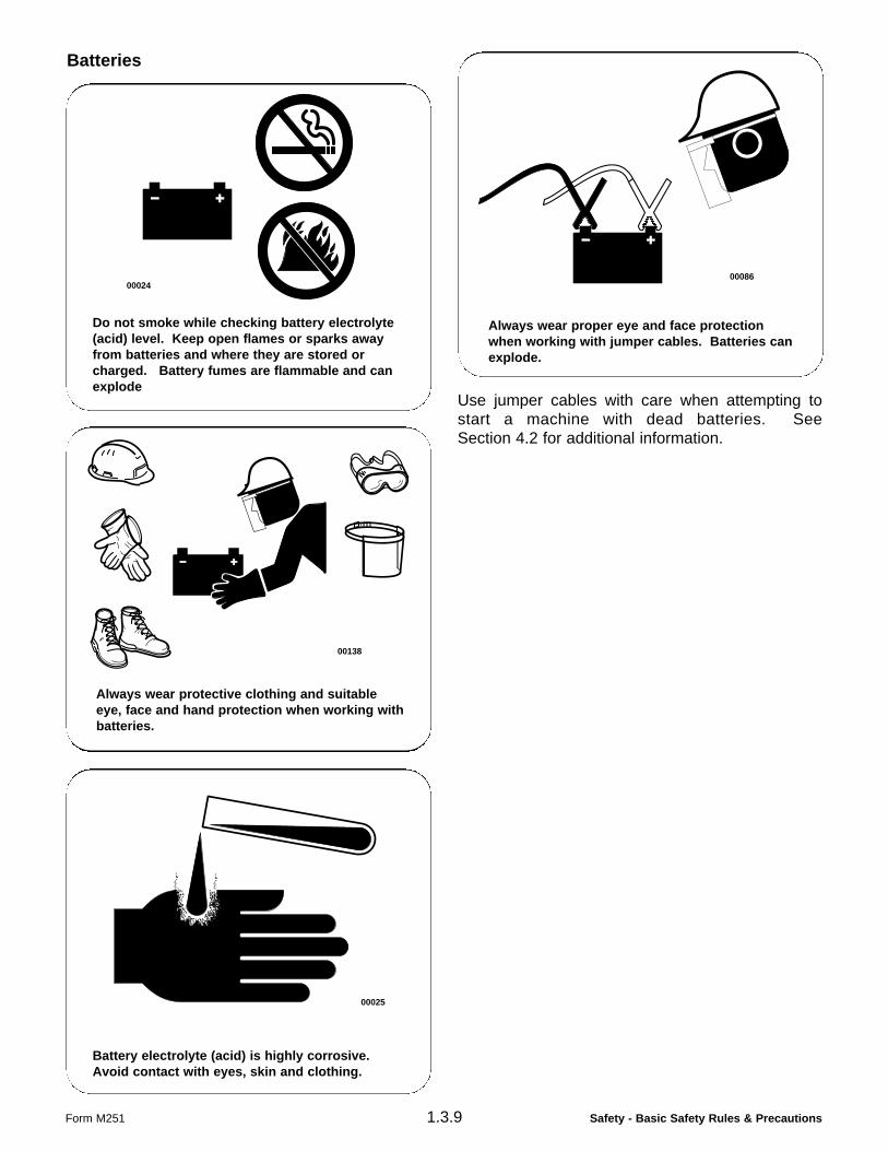
Batteries
Use jumper cables with care when attempting tostart a machine with dead batteries. SeeSection 4.2 for additional information.
Form M251
Always wear proper eye and face protectionwhen working with jumper cables. Batteries canexplode.
00086
Do not smoke while checking battery electrolyte(acid) level. Keep open flames or sparks awayfrom batteries and where they are stored orcharged. Battery fumes are flammable and canexplode
00024
Battery electrolyte (acid) is highly corrosive.Avoid contact with eyes, skin and clothing.
00025
Always wear protective clothing and suitableeye, face and hand protection when working withbatteries.
00138
Safety - Basic Safety Rules & Precautions 1.3.10
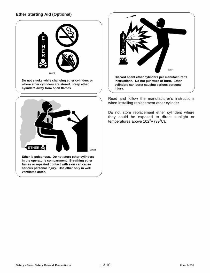
Ether Starting Aid (Optional)
Read and follow the manufacturer’s instructionswhen installing replacement ether cylinder.
Do not store replacement ether cylinders wherethey could be exposed to direct sunlight ortemperatures above 102oF (39oC).
Form M251
ETHER
Do not smoke while changing ether cylinders orwhere ether cylinders are stored. Keep ethercylinders away from open flames.
00023
ETHER
Ether is poisonous. Do not store ether cylindersin the operator's compartment. Breathing etherfumes or repeated contact with skin can causeserious personal injury. Use ether only in wellventilated areas.
00022
ETHER
Discard spent ether cylinders per manufacturer’sinstructions. Do not puncture or burn. Ethercylinders can burst causing serious personalinjury.
00034
Safety - Basic Safety Rules & Precautions1.3.11
Asbestos Information
Use caution to avoid breathing asbestos dust thatmay be generated by handling componentscontaining asbestos fibers. If asbestos dust isinhaled, it can be hazardous to your health.Components that could be installed in TIMBTECHydro-Skidders that may contain asbestos fibersare brake pads, brake band and lining assembliesand some gaskets. The asbestos in thesecomponents are usually bound in a resin or sealedin some way. Normal handling is not dangerous aslong as airborne dust which contains asbestos is notgenerated.
If dust which can contain asbestos is present, thereare several common sense guidelines that shouldbe followed:
Never use compressed air for cleaning asbestoscontaining materials.
Avoid brushing or grinding of asbestos containingmaterials.
For clean up, use wet methods or a vacuumequipped with a high efficiency particulate air(HEPA) filter.
Use exhaust ventilation on permanent machiningjobs.
Wear an approved respirator if there is no other wayto control the dust.
Comply with applicable rules and regulations for thework place (for example in the U.S.A., OSHArequirements as set forth in 29 CFR 1910.1001).
Follow environmental rules and regulations fordisposal of asbestos.
Avoid areas where asbestos particles might be inthe air.
Form M251

Safety - Basic Safety Rules & Precautions Form M251
THIS PAGE LEFT BLANK FOR NOTES