introduction, the mixer project
TRANSCRIPT

H-Mode mixer comparison
PA3AKE Page 1 3/5/2007
Introduction, the mixer project
Recently I renewed my interest in HAM radio and especially home brewing receivers/transceivers after a long period of other activities. I was quick to decide to design and build an HF all band transceiver. The plan was to use as much as possible proven designs freely available on the internet while maintaining a high degree of experimentation as that is what I like most of home brewing. I did not intend to build a kit.
The first version of the receivers front-end consisted of a preamplifier followed by an SL6440 Plessey mixer and a frequency stabilized (huff/puff) free running VFO. Soon the VFO was replaced by AD9951 DDS technology when I learned about that on the net. This was a real improvement with regard to controlling the receiver more in software but also because of the AD9951’s excellent phase noise properties. Although I had no means at that time to accurately quantify the dynamic range and intercept point properties of my construction efforts, I felt that there was a lot to be improved and that I needed a very different configuration without a preamplifier in front off the mixer. But with the SL6440 that was not possible because of the intrinsic NF of that circuit. It was not long before I stumbled on the CDG2000 homepage and started to study and appreciate the designs presented there including the H-Mode mixer circuit. I build the H-Mode mixer, Manhattan style with trifilar FT37-43 transformers, moved the preamplifier behind the INRAD crystal filter and had a sensitive receiver most likely with an intercept point much better then with my earlier attempt! This was the point where the DDS spurs started to get my attention, as their level and numbers where really unacceptable. With all the gain inside and in front off the SL6440 they had been swamped into the noise floor, but now no more... This was also the time when I emailed Colin Horrabin G3SBI, the inventor of the H-Mode mixer circuit, with a question about the input termination of the mixer in the CDG2000 front-end. I was puzzled by the fact that no effort was spent on terminating the RF-port of the mixer with 50 ohms consistently, while this was considered to be very important with the high-level ring-mixers to obtain the best IP3. Funny enough, although the H-Mode mixer is very insensitive indeed regarding the intercept point and its input termination, the input termination issue came back to me in the light of the DDS spurs. As I was going deeper into HF front-end design, I had bought a surplus spectrum analyzer with tracking generator in the need for a more solid quantification of the progression made or not made. While using the tracking generator as a signal source for measuring the MDS level of the receiver, I found that the spurs were much less present in numbers and level when I connected the generator through an 80dB step attenuator directly to the mixer RF-port instead of to the 4-pole band-pass filters normally in front of the mixer. The spur pollution was actually about acceptable in that configuration. A

H-Mode mixer comparison
PA3AKE Page 2 3/5/2007
flat 50-ohm termination brought the spurs to their knees, although I had no explanation for this effect at that point. To quantify this I recorded the available spurs on 15M as there were so many on that band. I recorded all reasonably loud spurs that I could find while tuning the DDS slowly with a step rate of 5Hz. That gave me 132 (!) spurs in total and the levels were measured in dB above MDS in SSB bandwidth with DL4YHF's excellent Spectrum Lab PC software. The average level of those spurs with the band-pass filter in front was 13,2dB (!) above MDS. Terminating the mixer’s RF-port with 50 ohms reduced that level to -5,9dB. Inserting a diplexer between the filter and the mixer reduced the spur level to -4,7dB. At that point the solution looked simple: Add diplexers for each band, 9 or 10 total, and we are done. Although the diplexers would have improved things greatly, I was looking for something better as the diplexers looked more like a workaround then to a solution to the problem. Further more they would add extra attenuation in front of the mixer and therefore directly worsen the NF. And there were some unanswered questions too. Why did many of the spurs reduce so much with the 50 ohm input termination, while still some were not influenced a bit and remained equally loud? I have come to the following categorization of the DDS spurs:
1. Direct spurs. These spurs coincide with the IF frequency and leak directly from the LO-port to the IF-port. Obviously, there will not be so many of this kind and the huge amount of spurs that I have encountered could not be explained this way.
2. Direct heterodyning spurs. These are strong spurs available at the LO-port that
directly heterodyne with signals received at the RF-port of the mixer. These are the spurs that are related to strong input signals and disappear completely if the input signals are removed. Also this category did not explain all the spurs.
3. Self heterodyning spurs. These spurs are caused by spurs that leak from the LO-
port to the RF-port and then heterodyne with anything available on the LO-Port to produce signals at the IF-port at the IF frequency. This category produces vast amounts of spurs. All spur combinations in the full 200MHz AD9951 DDS output spectrum that are 9MHz apart (my IF frequency) will produce a spur within the IF bandwidth! This happens to be also the spur category that reacts to the mixer input termination. When a band-pass filter is connected to the mixer, all combinations in the stop-band of the filter are almost 100% reflected back into the mixer. With a 50 ohm resistive termination they are much more absorbed and their effect is much reduced.
What can be done about these different categories? Reducing the spur levels at the LO-port is the number one cure to category 1. This can be done in two ways: Band-pass filtering of the DDS output and increasing the clock frequency of the DDS to the limit. The lower the DDS output frequency with respect to the nyquist frequency the better is

H-Mode mixer comparison
PA3AKE Page 3 3/5/2007
the wideband spur free dynamic range (SFDR). As I operate the AD9951 at 500MHz not much improvement can be done there except waiting for the next generation of 1GHz DDS parts (AD9910 and friends). Better mixer symmetry reducing the LO-IF-port leak will help too. The cure for category 2 spurs is the same as for category 1. Filtering of the DDS output. In addition, filtering of the mixer input will help too as less combinations at the IF frequency will be found if the input spectrum is limited as much as possible. Improving mixer symmetry will not help at all for this category. The cure for category 3 spurs is: Filtering the DDS with a band-pass filter with a pass band smaller then the IF frequency. Any combinations that heterodyne to the IF frequency will be eliminated then. Furthermore, any improvements to the mixers symmetry will reduce the spur levels at the RF-port and subsequently the results at the IF-port. And last but not least, resistive 50 ohms termination at the RF-port will absorb the leaked spurs as well. Because improving mixer symmetry really helps for 2 of the 3 categories and can be implemented at one place for all amateur bands, being the mixer, this is an approach that asks for it to be optimized as much as possible. The first successful steps in that direction were improving the transformers of the H-Mode mixer. I replaced my home-made FT37-43 transformers with Minicircuit TT4-1A used in the CDG2000 and observed lower spur levels. Next came Colin’s tip to use the 74AC74E (DIL14) or 74AC74M (SOIC14) from Texas Instruments in the squarer as those parts have balanced propagation delays in contrast to the ordinary 74AC74. This again reduced the average spur levels. Around that time, Colin noticed that Fairchild semiconductors had not been sitting still after introducing the FST3125 bus-switch that made the H-Mode mixer so successful. Many new switches were available now, most noticeably the category of video-switches. A sort of drop-in part for the original FST3125 is the FSAV332 although in QSOP rather then SOIC package. FSAV332 looked especially promising as its datasheet states equal on/off times which could further help to improve symmetry. Also other switches looked interesting like the FSAV330 which contains a couple of SPDT type switches that could simplify the layout of the H-Mode mixer. At that point I wanted to have a more systematic approach and decided to test a couple of those switches in a fair way, such that the results could be compared. Initially my comparison consisted of FSAV430, FSAV450, FSAV330, FSAV332 and the FST3125 as a reference. At that time I could only measure IP3 on 80M with 2 crystal oscillators with stock crystals about 100KHz apart. This worked quit well and I could measure IP3 well over +40dBm, but I had the nagging feeling that I was blind on what happened with the intercept point on other bands like 10M or even higher. So I ended up building two generators based on the AD9951 DDS to give me the ability to measure IP3 on any band and at any offset I wanted to. This was a little project on its own and it turned out not to be completely trivial to measure IP3 well above +40dBm on all bands. The higher the frequency, the more built-in IMD I encountered. The end-result is

H-Mode mixer comparison
PA3AKE Page 4 3/5/2007
described in the next chapter of this document and is good enough to measure the H-Mode mixer well above +40dBm on all bands. With the all-band IP3 measuring capabilities available a good comparison of the different mixers was beginning to get shape. It turned out that IP3 peaked much on 80M and 40M, where it is needed most, but would not maintain a > +40dBm level on the higher bands. So apart for trying to get good symmetry to fight the spurs a second goal became getting a mixer configuration that would do better then +40dBm on all HF bands. FSAV332 turned out to improve over FST3125, but the SPDT mixers were disappointing. The one that had very good symmetry (FSAV430) had unacceptable low IP3. And the FSAV330 did not come close to the FSAV332. The hopes had been high for the SPDT type mixers also because the layout of the mixer was much more optimal then possible with FST3125 or FSAV332, at least on a single sided board with a ground plane. All switches tested so far had in common that the mixer could be build with just one device. Not a surprise with the need for symmetry in mind. Colin again tipped of the NC7SZ384 and FSA3157 in the “analog-switches” category from Fairchild. They required respectively 4 and 2 devices to build a mixer with. Especially the FSA3157 was very good with spurs and IP3. Surprisingly this was an SPDT device! Because it was so good I decided to test this mixer with a fundamental frequency squarer, which is attractive as the SPDT switches do not need to be driven with complementary LO signals. This was also induced by the wish to keep the LO frequency as low as possible to get the best wideband SFDR from the DDS. The other reason was that one way or another, all SPDT mixers tested so far showed rather poor RF-IF-port isolation indicating that the mark/space ratio of the LO needed to be slightly different in this mixer configuration. So I tested the FSA3157 with Colin’s 74AC04 fundamental frequency squarer circuit which is a variation of the well known 74AC86 squarer, but without the complementary signal requirement. This turned out to be very good indeed. The IP3 remained at the good levels it already had, but the spurs could virtually be nulled out, although be it at the cost of poor RF-IF isolation. At this point the only goals not met were IP3 > +40dBm on all HF bands, and now also to improve RF-IF block. Because quit a few different switches had been tested so far, the attention was going into the direction of the transformers now. Not in the last place because of Harold E. Johnson W4ZCB recommendation to have a look at 1:1 transformers instead of the 1:4 transformers used traditionally in the H-Mode mixer circuit. Minicircuits have introduced a couple of less expensive wideband transformers looking promising given their insertion and return loss plots. The latest datasheets of ADTT1-1 and ADTT4-1 also showed good phase and amplitude balance data, which is interesting from a symmetry point of view. Finally the ADTT1-1 transformer solved the IP3 and RF-IF isolation problem. IP3 is now well over +40dBm on all HF bands and still very good at 6M and even 4M! Spurs are at -9.3dB, the lowest level ever measured in this project, at the best possible RF-IF isolation around -60dB! Sensitivity to the bias point is also low. The price to be paid comes with a
H-Mode mixer comparison
PA3AKE Page 5 3/5/2007
slightly increased conversion loss of around -0,4dB on most bands. Apparently at the 50 ohms level, the Ron of the switches is starting to play a role, but not much. With the category 3 spurs so low now with this mixer configuration, it is almost a pitty to have to implement a lot of DDS band-pass filtering to fight especially category 2 spurs. After the overall success of the ADTT1-1 transformer, except for conversion loss, 4 more Minicircuits 1:1 transformers have been tested. These transformers are designed to be very efficient at very low frequency (>15..30KHz). Initially, expectations were low with regard to for instance IP3, but this turned out to be a surprise. These transformers were the best with regard to IP3, also on the higher bands. They all did >+40dBm on HF and some even on 6M! And last but not least conversion loss is very good indeed. The only downside is the rather poor spur reduction possible with this category of transformers.
H-Mode mixer comparison
PA3AKE Page 6 3/5/2007
IP3 measurement / limitations
Signal Generators and Hybrid Combiner
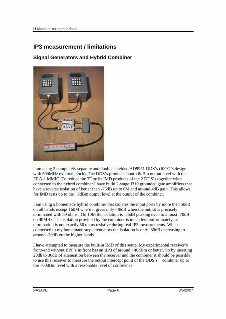
I am using 2 completely separate and double shielded AD9951 DDS’s (I0CG’s design with 500MHz external clock). The DDS’s produce about +8dBm output level with the ERA-1 MMIC. To reduce the 3rd order IMD products of the 2 DDS’s together when connected to the hybrid combiner I have build 2-stage J310 grounded gate amplifiers that have a reverse isolation of better then -75dB up to 6M and around 4dB gain. This allows for IMD tests up to the +6dBm output level at the output of the combiner. I am using a homemade hybrid combiner that isolates the input ports by more then 50dB on all bands except 160M where it gives only -48dB when the output is precisely terminated with 50 ohms. On 10M the isolation is -56dB peaking even to almost -70dB on 40MHz. The isolation provided by the combiner is much less unfortunately, as termination is not exactly 50 ohms resistive during real IP3 measurements. When connected to my homemade step attenuators the isolation is only -30dB decreasing to around -20dB on the higher bands. I have attempted to measure the built-in IMD of this setup. My experimental receiver’s front-end without BPF’s in front has an IIP3 of around +40dBm or better. So by inserting 20db to 30dB of attenuation between the receiver and the combiner it should be possible to use this receiver to measure the output intercept point of the DDS’s + combiner up to the +60dBm level with a reasonable level of confidence.

H-Mode mixer comparison
PA3AKE Page 7 3/5/2007
The following OIP3 observed of the DDS’s & combiner described above with 20 kHz spacing:
2 x DDS + Combiner Output level OIP3 IMD
Band dBm dBm dBc
160 6,2 57,9 -103 80 6,3 56,3 -100 40 6,6 58,6 -104 30 6,6 57,1 -101 20 6,6 56,6 -100 17 6,5 53,5 -94 15 6,3 52,3 -92 12 6,1 51,4 -91 10 5,9 49,2 -87 6 3,0 45,7 -86
The listed OIP3 values are valid ONLY at the corresponding output level. Every dB of attenuation following the combiner must be subtracted from those values to reflect the actual OIP3 at that point. For this reason the attenuation to the desired output level to do the IP3 measurement should be done BEFORE the combiner. Each dB of attenuation before the combiner results in 2dBs of better isolation between the 2 DDS’s. This might improve the listed IMD levels. Further more any IMD produced by the combiner’s toroid core will be less if the levels there are kept to the minimum. So this system is suitable to measure up to +50dBm on 160M-20M. On 17M-10M +45dBm is the limit. I have not determined the cause of the increased IMD at higher frequencies. It could be the combiner or the output amplifier or both. This picture (Wandel&Goltermann SNA-62) confirms at least -90dBc IMD products with 1dBm input levels on 40M (OIP3>=+46dBm). Funny enough a few -80dBc or less AD9951 spurs are visible too! This is the best I can squeeze out of this instrument.

H-Mode mixer comparison
PA3AKE Page 8 3/5/2007
Post Mixer Roofing Filter Because the goal is to measure only the IP3 of the 1st mixer embedded in the receiver’s front-end, I have checked the IP3 of the 9MHz hybridized quartz roofing filter (CDG2000 design) following the mixer. To assess the 1:3 IMD behaviors, the filter has been measured at as a wide range of input levels as possible:
Roofing filter 20KHz Level
dBm IIP3 4,5 51,0 2,5 49,0 0,5 47,8
-1,5 45,8 -3,5 44,0 -5,5 42,5 -7,5 41,0 -9,5 41,0
This roofing filter will definitely limit the IP3 of some of the better H-Mode mixer configurations as the IP3 of the filter is around +42,5dBm at the -5dBm level encountered when measuring the mixer at the 0dBm level. The roofing filter also is clearly not following 1:3 IMD behavior. The good news however is that it is bottoming out at +41dBm allowing for a front-end in the plus forties. To minimize the bad effect of the roofing filter during IP3 mixer measurements, a -12dB pad is inserted between the mixer and the filter during measurements.

H-Mode mixer comparison
PA3AKE Page 9 3/5/2007
Pre Mixer Band-pass Filters High dynamic range does not come easily. Like the hybridized quartz roofing filter, the band-pass filters in front of the mixer are forming an IP3 bottleneck too. Although they are not switched in during IP3 measurement it is interesting to see how they perform. This table shows the IIP3 at 0dBm and +6dBm input levels:
BPF IIP3 (dBm) QL Core
Band 0dBm 6dBm 4x
160 35,7 36,2 6,0 T50-2 80 38,2 39,5 5,3 T50-2 40 36,7 37,7 15,1 T50-6 30 35,5 36,5 26,7 T50-6 20 36,2 37,2 28,5 T50-6 17 36,6 41,3 23,8 T50-10 15 39,6 42,1 30,5 T50-10 12 39,3 40,8 28,8 T50-10 10 39,8 40,5 12,9 T50-10
Except for 17M and 15M, where there is a rather large discrepancy between the IIP3 at 0dBm and 6dBm, the measured IIP3 looks rather consistent. These BPF’s are 4-trap capacitive top coupled (cohn) filters designed to have the smallest bandwidth preferably with losses under -3dB. Therefore loaded Q is rather high on some bands. It is obvious that these BPF’s need to be redesigned to fully exploit the IP3 performance of the H-Mode mixer. One problem with the filters might be that they are build with cheap, mostly black NP0 ceramic capacitors, except on the lower 2 bands where the even worse violet variety is used. An experiment on 15M with a CDG2000 alike filter with three T50-10 cores and mica caps (series-shunt-C filter) with a loaded Q of around 15 gave better results: +43,1dBm, +44,6dBm at 0, respectively 6dBm input levels. I will probably have to go for the big T68 cores on the lower bands to have the best possible IP3 there.

H-Mode mixer comparison
PA3AKE Page 10 3/5/2007
Mixer Transformers
Having seen the disappointing results of the BPF’s with the big Amidon T50 iron powder cores, it is interesting to see how the tiny Minicircuits 1:4 and 1:1 transformers used in the H-Mode mixer behave. In this test 2 cascaded transformers are used and the IIP3 is measured while going from 50 to 200 and back to 50 ohms.
Transformer IIP3 (dBm) @ +6dBm input Band TT4-1A T4-1 FT37-43 ADTT4-1 ADTT1-1 T1-1T ADTT1-6 ADT1-6T TT1-6 T1-6T
160 43,4 40,2 43,7 45,7 44,2 40,7 49,7 48,7 48,9 49,4 80 46,1 43,8 49,6 51,1 47,8 44,8 54,6 53,8 53,3 54,3 40 51,4 48,4 53,6 56,4 54,4 53,4 54,9 53,9 53,9 54,1 30 52,6 51,6 54,1 52,6 52,6 51,1 49,4 49,6 49,9 50,4 20 49,1 49,1 50,1 49,4 48,1 49,1 48,4 47,9 48,4 48,9 17 50,5 50,0 51,5 50,5 48,8 49,0 48,3 48,0 49,0 49,5 15 49,3 49,3 49,6 50,8 48,8 49,3 47,8 49,1 48,8 49,6 12 47,6 48,4 48,9 48,4 46,9 47,4 44,4 45,6 45,4 46,1 10 45,4 46,4 46,2 45,4 43,4 43,7 43,9 42,7 42,7 44,2
6 43,0 44,2 43,7 44,2 41,2 42,5 39,0 40,0 40,2 40,2 All transformers do > +40dBm on all bands (almost), but the best transformer in this test seems to be the ADTT4-1. Things are more complicated when the transformers are applied in the H-Mode mixer as it turned out. All these transformers are tested with the FSA3157 mixer.

H-Mode mixer comparison
PA3AKE Page 11 3/5/2007
Fairchild switches The following Fairchild bus/video/analog switches are tested in the H-Mode mixer circuit:
1. 1 x FSAV430 + 74AC74 div2 squarer 2. 1 x FSAV450 + 74AC74 div2 squarer 3. 1 x FSAV330 + 74AC74 div2 squarer 4. 1 x FSAV332 + 74AC74 div2 squarer 5. 1 x FST3125 + 74AC74 div2 squarer 6. 4 x NC7SZ384 + 74AC74 div2 squarer 7. 2 x FSA3157 + 74AC74 div2 squarer 8. 2 x FSA3157 + 74AC04 fundamental squarer
All mixers are constructed on small single sided PCB’s with a ground plane of about 1.5 by 2 inches. All components are SMD. The following configuration is used for all mixers:
• Transformer: Mini-circuits TT4-1A. The same 3 transformers at the same positions are used for all mixers. The transformers are mounted on DIP6 socket for easy transfer between the different mixers.
• The squarer is a divide by 2 squarer with the Texas Instruments 74AC74M except for mixer 8 where an adjustable fundamental mode squarer with a 74AC04D is used.
• The PCB layouts are as compact as possible and very similar to each other, although some switches allow for a more compact layout then others.
In earlier tests the FST3125 showed considerable degradation in symmetry on the higher bands leading to bad spur reduction. With the PCB’s used in this test the difference between the FST3125 and the FSAV332 is not so profound. But still the FSAV332 seems a better choice. Compact construction appears to plays an important role with the H-Mode mixer circuit. Some common observations for all mixers:
• Conversion loss was always around -4.9dB to -5.0 dB for all mixers when using TT4-1A transformers. Not much difference there. Conversion loss seems to be determined by the transformers rather then the switches.
• The SPDT type mixers (FSAV430, FSAV450, FSAV330, FSA3157) show considerably less 9MHz RF-IF isolation then the FSAV332 or FST3125 when using the fixed divide by 2 74AC74 squarer. The SPDT type mixers need a slightly adjusted squarer, a little bit off 50% duty cycle for better RF-IF isolation.
• All mixers are found to follow a more or less 1:3 IMD behavior, but not exactly. • All mixers show a steadily decreasing IIP3 on higher frequencies. Some mixers
are more affected then others. The transformers are very important.

H-Mode mixer comparison
PA3AKE Page 12 3/5/2007
• Devices that allow up to 7V Vdd are to be preferred for highest IP3. Next follows an overview of the results of each mixer that was investigated. The following can be noted with regard to all the IP3 measurements:
• IP3 measurements are done with 20 kHz spaced tones at around 0dBm on all HF bands. On 80M measurements at levels ranging from -6dBm to +5dBm are carried out to check the validity of the results. (1:3 3rd order behavior)
• I have measured the FST3125 at 10 KHz, 20 KHz, 50 KHz and 100 KHz and the
results are very similar. No big surprises at different spacing, so I measured all mixers at 20 kHz to keep the report compact.
• The IP3 has also been determined separately for the low and the high IMD
product. Most of the time the differences are minimal, rarely exceeding 1 dBm, usually are the same. For compactness and accuracy the average of the 2 values is reported.
• The RF termination of the mixer sometimes influences the intercept point
measurement considerably. After it was observed that a step attenuator set at 0dB between the hybrid combiner and the mixer made a noticeable difference to the IP3 (usually less IMD, but not always…) all IMD levels were recorded with no attenuator between the hybrid and the mixer. Some mixer configurations are more susceptible to this effect then others.
The test result of each mixer configuration is presented in a table with a row per amateur band and the following columns:
1. Band. The amateur band the measurement was made on. 2. BPF-IL . Band pass filter insertion loss of the filter in front of the mixer. 3. Mixer-CL . Mixer conversion loss measured around 0dBm input level. 4. MDS – BPF. MDS level observed without the BPF in front of the mixer. 5. MDS + BPF. MDS level observed with the BPF in front of the mixer. 6. IF-Rej . The mixers RF-IF isolation at 9MHz IF frequency. 7. Spur-Avg. The average level above MDS of 132 spurs on 15M. 8. IIP3 @ -6dBm. The IIP3 measured at -6dBm input level. 9. IIP3 @ -3dBm. The IIP3 measured at -3dBm input level. 10. IIP3 @ 0dBm. The IIP3 measured at 0dBm input level. 11. IIP3 @ +3dBm. The IIP3 measured at +3dBm input level. 12. IIP3 @ -5dBm. The IIP3 measured at +5dBm input level. 13. Bias. The bias point voltage with the best IP3. 14. IIP3 . The IIP3 at 0dBm input level at that best bias point.
Column 2 to 4 may need some extra explanation. These columns are added to show an interesting discrepancy between the MDS level with and without the band-pass filter in front of the mixer. One would expect that the difference in MDS should match the IL of
H-Mode mixer comparison
PA3AKE Page 13 3/5/2007
the filter. With most mixer configurations especially on the higher bands this was certainly not the case at all. MDS would drop severely with the BPF in front on some bands. The cause of this is excess spurs that are actually forming an increased noise floor! One can actually hear a crowd of weak spurs at or around MDS level flowing into each other. There is another intriguing up to now unsolved issue with the MDS level. One would expect a -3dB hit when no band-pass filter is in front of the mixer, caused by the noise at the image frequency that is not filtered away. However, this -3dB hit is not observed at all. I have no explanation. The measured MDS level is corresponding well with all the known losses of the mixer, the hybridized roofing filter and so forth. Is this something special with the H-Mode mixer? This asks for a test with a ring mixer.

H-Mode mixer comparison
PA3AKE Page 14 3/5/2007
FSAV430
The FSAV430 (QSOP-16 package) contains 4 SPDT switches with a common control line. Only 2 switches are needed to implement the H-Mode mixer. The PCB layout of the FSAV430 with the 3 TT4-1A transformers is very compact indeed. The FSAV430 does not require an 74AC74 divide by two squarer as it does not need both Q and !Q. However in this test the 74AC74 squarer is used. The following table summarizes the measurements with the FSAV430:
FSAV430 + TT4-1A + 74AC74 Vdd = 3.3V, Vbias = 1.65V Best bias
BPF mixer MDS -dBm IF rej spur mixer IIP3 (dBm) @ 20KHz spacing Bias IIP3 Band IL
-dB CL -dB
- BPF
+ BPF
-dB
avg dB
-6 dBm
-3 dBm
0 dBm
+3 dBm
+5 dBm V
0 dBm
160 3,3 5,08 132 128 41,2 33,0 1,65 33,0
80 1,4 5,00 133 131 40,4 31,3 31,6 32,3 31,3 1,65 32,3
40 2,3 5,00 133 130 39,2 31,6 1,65 31,6
30 3,4 5,00 133 129 38,4 31,2 1,65 31,2
20 3,4 5,00 133 129 35,6 30,5 1,65 30,5
17 3,0 5,00 133 129 32,8 30,1 1,65 30,1
15 3,9 5,04 133 128 32,0 -4,8 28,9 1,65 28,9
12 3,7 4,94 133 129 31,2 28,3 1,65 28,3
10 2,3 5,08 133 129 30,8 29,2 1,65 29,2
6
I was not able to do measurements on 6M with this mixer as the 74AC74 on this board failed to operate at those frequencies. (51 + 9) * 2 = 120MHz. The 74AC74M is specified at max 125MHz clock. This was the only mixer that failed on 6M, so it was a poor 74AC74M from that batch.

H-Mode mixer comparison
PA3AKE Page 15 3/5/2007
The FSAV430 is tested at 3.3V Vdd. From the datasheet that contains a graph plotting Ron versus Vin it is obvious that this switch should be biased at the midpoint. Experiments do confirm this. The best bias point is 1.65V. IP3 measurements showed values around +31dBm. Due to its low Vdd the IP3 was degrading fast at input levels above +3dBm. The IP3 does not degrade as much at higher frequencies like the other mixers. The FSAV430 showed very good spur reduction of all mixers tested at average -4.8dB below MDS for 130 spurs on 15M. The FSAV430 sounds really quiet with respect to the spurs, although a number of spurs still remain equally strong. The RF-IF isolation at 9 MHz is poor when compared with for example the FSAV332 or the FST3125.

H-Mode mixer comparison
PA3AKE Page 16 3/5/2007
FSAV330
The FSAV330 (SOIC-14 package) contains 4 SPDT switches with a common control line. Only 2 switches are needed to implement the H-Mode mixer. The PCB layout of the FSAV330 with the 3 TT4-1A transformers is very compact indeed. The FSAV330 does not require an 74AC74 divide by two squarer as it does not need both Q and !Q. However in this test the 74AC74 squarer is used. The following table summarizes the measurements with the FSAV330:
FSAV330 + TT4-1A + 74AC74 Vdd = 7.0V, Vbias = 1.9V Best bias
BPF mixer MDS -dBm IF rej spur mixer IIP3 (dBm) @ 20KHz spacing Bias IIP3 Band IL
-dB CL -dB
- BPF
+ BPF
-dB
avg dB
-6 dBm
-3 dBm
0 dBm
+3 dBm
+5 dBm V
0 dBm
160 3,3 5,08 132 128 33,6 41,9 1,9 41,9
80 1,4 5,00 133 131 33,2 40,5 41,2 42,2 43,0 33,2 1,9 42,2
40 2,3 4,96 133 130 32,0 40,4 2,0 40,4
30 3,4 4,96 133 129 32,4 39,0 1,9 39,0
20 3,4 4,96 133 129 31,6 37,4 2,0 37,4
17 3,0 4,96 133 129 30,8 37,3 2,0 37,3
15 3,9 4,96 132 128 28,4 9,3 35,1 2,0 35,1
12 3,7 4,92 133 129 27,6 34,8 2,0 34,8
10 2,3 5,00 133 125 28,4 35,5 2,3 36,5
6 5,72 126 128 23,2 34,5 3,0 42,0
The FSAV330 is tested at 7V Vdd. The best overall bias point is found to be at 1.9V. Especially on 160M and 80M this bias point is improving over the midpoint. On the higher bands the difference is not big except on 6M where the IMD drops considerably at higher bias point values. Although I do not trust that figure very much as it is NOT following 3rd order behavior at all! The optimum bias point is found to depend on the input termination of the mixer. A step attenuator set at 0dB before the mixer gives different results then no step attenuator at all.

H-Mode mixer comparison
PA3AKE Page 17 3/5/2007
Because of the low bias point voltage, IP3 above +3dBm input level is deteriorating rapidly. The spur reduction on 15M is the worst of all tested mixers, with an average spur level of +9.3 dB above MDS for 130 spurs. Like the FSAV430, the 9MHz RF-IF isolation is not very impressive. MDS level on 6M is very poor indeed. Finally an experiment is done by connecting the two unused switches in parallel with the other two. Only +/- 0.1dB improvement in conversion loss was observed. The IP3 is not influenced at all. The spur reduction is noticeably worse.

H-Mode mixer comparison
PA3AKE Page 18 3/5/2007
FSAV450
The FSAV450 (QSOP-16 package) contains 4 SPDT switches with a common control line. Only 2 switches are needed to implement the H-Mode mixer. The PCB layout of the FSAV450 with the 3 TT4-1A transformers is very compact indeed. The FSAV450 does not require an 74AC74 divide by two squarer as it does not need both Q and !Q. However in this test the 74AC74 squarer is used. The following table summarizes the measurements with the FSAV450:
FSAV450 + TT4-1A + 74AC74 Vdd = 5.0V, Vbias = 1.7V Best bias
BPF mixer MDS -dBm IF rej spur mixer IIP3 (dBm) @ 20KHz spacing Bias IIP3
Band IL -dB
CL -dB
- BPF
+ BPF
-dB
avg dB
-6 dBm
-3 dBm
0 dBm
+3 dBm
+5 dBm V
0 dBm
160 3,3 5,08 132 128 32,0 41,7 1,70 41,7
80 1,4 5,04 133 131 31,6 35,7 37,0 39,5 36,7 31,2 1,70 39,5
40 2,3 5,00 133 129 30,4 36,7 1,70 36,7
30 3,4 5,00 133 129 30,4 36,0 1,70 36,0
20 3,4 4,96 133 129 29,2 37,7 1,70 37,7
17 3,0 5,00 133 129 27,6 38,8 1,70 38,8
15 3,9 5,00 133 128 27,2 1,3 37,1 1,75 37,1
12 3,7 5,04 133 129 26,4 33,8 1,80 33,8
10 2,3 5,04 133 129 24,8 32,5 1,70 32,5
6 5,44 131 20,8 26,7 1,90 26,7
The FSAV450 is tested at 5V Vdd with bias at 1,7V. The optimum bias point is found to depend significantly on the input termination of the mixer. A step attenuator set at 0dB before the mixer gives very different results then no step attenuator at all. All mixers that depend on the bias point had this behavior, but the FSAV450 was the worst.
H-Mode mixer comparison
PA3AKE Page 19 3/5/2007
Because of the low bias point voltage, IP3 from +3dBm input level and up is deteriorating rapidly. Rapidly degrading IP3 with frequency, but considering that this is a 5V device still rather good! The spur reduction on 15M is rather good. Like the FSAV430 and FSAV330, the 9MHz RF-IF isolation is not very impressive

H-Mode mixer comparison
PA3AKE Page 20 3/5/2007
FSAV332
The FSAV332 (QSOP-16 package) contains 4 SPST switches with a separate control line each. All 4 switches are needed to implement the H-Mode mixer. The PCB layout of the FSAV332 with the 3 TT4-1A transformers is less compact then the layout of the SPDT type mixers. Especially the connection between the outer transformers is considerably longer. The FSAV332 requires an 74AC74 divide by two squarer as it does need both Q and !Q. The following table summarizes the measurements with the FSAV332 and the TT4-1A transformers:
FSAV332 + TT4-1A +74AC74 Vdd = 7.0V, Vbias = 3.5V Best bias
BPF Mixer MDS -dBm IF rej spur mixer IIP3 (dBm) @ 20KHz spacing Bias IIP3 Band IL
-dB CL -dB
- BPF
+ BPF
-dB
avg dB
-6 dBm
-3 dBm
0 dBm
+3 dBm
+5 dBm V
0 dBm
160 3,3 5,12 133 129 57,6 41,4 3,5 41,4
80 1,4 5,04 133 131 57,6 43,7 44,7 46,2 48,2 49,7 3,5 46,2
40 2,3 5,00 133 130 57,2 46,2 3,5 46,2
30 3,4 5,04 133 129 57,2 43,0 3,5 43,0
20 3,4 5,04 133 129 55,2 41,4 3,5 41,4
17 3,0 5,00 133 129 52,0 41,1 3,5 41,1
15 3,9 4,96 133 127 51,6 3,6 40,4 3,5 40,4
12 3,7 4,96 133 129 51,6 38,1 3,5 38,1
10 2,3 4,96 133 126 57,2 37,0 3,5 37,0
6 5,40 123 27,6 35,2 3,5 35,2
The FSAV332 is tested at 7V Vdd with bias at the mid point. There is no other point were the IMD dipped better. There is no steep dip. FSAV332 is rather insensitive with respect to the bias point.

H-Mode mixer comparison
PA3AKE Page 21 3/5/2007
I am not able to measure at -6dBm reliably as the 3rd IMD products are too close to the noise floor. Again degrading IP3 with frequency and peaking IP3 on 80M and 40M. 160M performance seems to suffer from the transformers limitations. The spur reduction on 15M is fairly good at 3,6 dB above MDS average per spur. Unlike the mixers with the SPDT type switches, the 9MHz IF rejection is very good at below -50dB fairly constant on all HF bands! MDS on 6M and RF-IF isolation are very poor indeed. High spur levels were observed on 6M. The FSAV332 is also tested with the ADTT1-1 1:1 transformer in order to verify the good results with these transformers obtained with the FSA3157 switches. The following table shows the results:
FSAV332 + ADTT1-1 + 74AC74 Vdd = 7.0V, Vbias = 3.5V Best bias
BPF Mixer MDS -dBm IF rej spur mixer IIP3 (dBm) @ 20KHz spacing Bias IIP3 Band IL
-dB CL -dB
- BPF
+ BPF
-dB
avg dB
-6 dBm
-3 dBm
0 dBm
+3 dBm
+5 dBm V
0 dBm
160 3,3 5,68 132 129 58,4 42,4 3,5 42,4
80 1,4 5,60 132 131 58,4 44,2 45,0 46,5 47,0 46,7 3,5 46,5
40 2,3 5,60 132 130 60,0 45,2 3,5 45,2
30 3,4 5,56 133 129 59,2 45,0 3,5 45,0
20 3,4 5,60 133 129 60,0 42,9 3,5 42,9
17 3,0 5,68 133 129 58,0 42,1 3,5 42,1
15 3,9 5,76 132 128 56,4 3,8 41,9 3,5 41,9
12 3,7 5,80 132 126 56,8 40,3 3,5 40,3
10 2,3 5,92 132 127 54,8 40,0 3,5 40,0
6 6,12 124 28,0 37,2 3,5 37,2
The FSAV332 is clearly a winner! With the ADTT1-1 transformer the IIP3 is > +40dBm on all HF bands and not bias point dependent. However spur levels are somewhat problematic and 6M performance is considerably less good, probably due to the limitations of the PCB layout of the mixer. The ADTT1-1 transformer, first tested with the FSA3157, improves the IP3 especially on the higher bands like it did with the FSA3157 mixer. The price to pay is the increase in conversion loss of roughly 0,6dB.

H-Mode mixer comparison
PA3AKE Page 22 3/5/2007
FST3125
The FST3125 (SOIC-14 package) contains 4 SPST switches with a separate control line each. All 4 switches are needed to implement the H-Mode mixer. The PCB layout of the FST3125 with the 3 TT4-1A transformers is less compact then the layout of the SPDT type mixers. Especially the connection between the outer transformers is considerably longer. The FST3125 requires an 74AC74 divide by two squarer as it does need both Q and !Q. The following table summarizes the measurements with the FST3125:
FST3125 + TT4-1A + 74AC74 Vdd = 7.0V, Vbias = 3.5V Best bias
BPF Mixer MDS -dBm IF rej spur mixer IIP3 (dBm) @ 20KHz spacing Bias IIP3 Band IL
-dB CL -dB
- BPF
+ BPF
-dB
avg dB
-6 dBm
-3 dBm
0 dBm
+3 dBm
+5 dBm V
0 dBm
160 3,3 5,08 133 129 52,8 41,9 3,5 41,9
80 1,4 5,04 133 131 52,8 44,7 44,2 45,2 46,5 47,7 3,5 45,2
40 2,3 5,04 133 130 53,2 43,7 3,5 43,7
30 3,4 5,00 133 129 53,6 41,5 3,5 41,5
20 3,4 5,00 133 129 54,0 40,4 3,5 40,4
17 3,0 4,96 133 128 52,4 39,3 3,5 39,3
15 3,9 4,96 133 127 52,8 4,3 39,1 3,5 39,1
12 3,7 4,92 133 129 49,6 37,3 3,5 37,3
10 2,3 5,00 133 125 48,4 36,5 3,5 36,5
6 5,40 125 28,0 34,7 3,5 34,7
The FST3125 is tested at 7V Vdd with bias at the mid point. There is no other point were the IMD dipped better. There is no steep dip. FST3125 is rather insensitive with respect to the bias point.

H-Mode mixer comparison
PA3AKE Page 23 3/5/2007
I am not able to measure at -6dBm reliably as the 3rd IMD products are too close to the noise floor. Again degrading IP3 with frequency and peaking IP3 on 80M and 40M. 160M performance seems to suffer from the transformers limitations. The spur reduction on 15M is fairly good, but slightly less then the FSAV332. Unlike the mixers with the SPDT type switches, the 9MHz IF rejection is very good at below -50dB fairly constant on most HF bands! MDS level on 6M and RF-IF isolation are very poor indeed. High spur levels were observed on 6M. The FST3125 really performs very much like the FSAV332, although the FSAV332 is slightly superior.
H-Mode mixer comparison
PA3AKE Page 24 3/5/2007
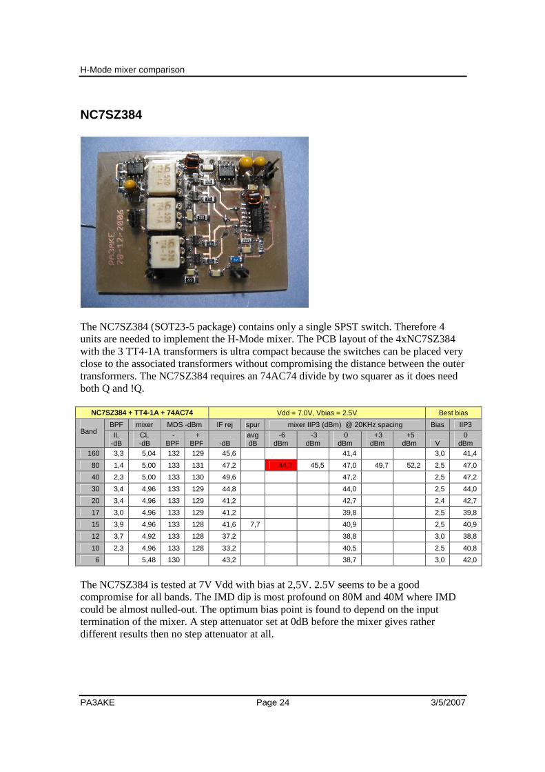
NC7SZ384
The NC7SZ384 (SOT23-5 package) contains only a single SPST switch. Therefore 4 units are needed to implement the H-Mode mixer. The PCB layout of the 4xNC7SZ384 with the 3 TT4-1A transformers is ultra compact because the switches can be placed very close to the associated transformers without compromising the distance between the outer transformers. The NC7SZ384 requires an 74AC74 divide by two squarer as it does need both Q and !Q.
NC7SZ384 + TT4-1A + 74AC74 Vdd = 7.0V, Vbias = 2.5V Best bias
BPF mixer MDS -dBm IF rej spur mixer IIP3 (dBm) @ 20KHz spacing Bias IIP3 Band IL
-dB CL -dB
- BPF
+ BPF
-dB
avg dB
-6 dBm
-3 dBm
0 dBm
+3 dBm
+5 dBm V
0 dBm
160 3,3 5,04 132 129 45,6 41,4 3,0 41,4
80 1,4 5,00 133 131 47,2 44,2 45,5 47,0 49,7 52,2 2,5 47,0
40 2,3 5,00 133 130 49,6 47,2 2,5 47,2
30 3,4 4,96 133 129 44,8 44,0 2,5 44,0
20 3,4 4,96 133 129 41,2 42,7 2,4 42,7
17 3,0 4,96 133 129 41,2 39,8 2,5 39,8
15 3,9 4,96 133 128 41,6 7,7 40,9 2,5 40,9
12 3,7 4,92 133 128 37,2 38,8 3,0 38,8
10 2,3 4,96 133 128 33,2 40,5 2,5 40,8
6 5,48 130 43,2 38,7 3,0 42,0
The NC7SZ384 is tested at 7V Vdd with bias at 2,5V. 2.5V seems to be a good compromise for all bands. The IMD dip is most profound on 80M and 40M where IMD could be almost nulled-out. The optimum bias point is found to depend on the input termination of the mixer. A step attenuator set at 0dB before the mixer gives rather different results then no step attenuator at all.

H-Mode mixer comparison
PA3AKE Page 25 3/5/2007
I am not able to measure at -6dBm reliably as the 3rd IMD products are too close to the noise floor. This mixer is keeping up good IP3 levels also on the higher bands! 160M performance seems to suffer from the transformers limitations. The spur reduction on 15M is pretty bad. Unlike the mixers with the SPDT type switches, the 9MHz IF rejection is rather good at below -40dB fairly constant on most bands! MDS level on 6M and RF-IF isolation are rather good too! IIP3 wise this mixer outperforms the FSAV332/FST3125 mixers. 4 separate (non-matched) packages that are adjacent on the reel don’t seem to degrade performance much.

H-Mode mixer comparison
PA3AKE Page 26 3/5/2007
FSA3157
The FSA3157 (SC70-6 package) contains only a single SPDT switch. Therefore 2 units are needed to implement the H-Mode mixer. The PCB layout of the 2xFSA3157 with the 3 TT4-1A transformers is ultra compact because the 2 switches can be placed very close to the corresponding transformers without compromising the distance between the outer transformers. The FSA3157 does not require an 74AC74 divide by two squarer as it does not need both Q and !Q. The following table lists the results with the FSA3157 and the 74AC74 div2 squarer:
FSA3157 + TT4-1A + 74AC74 Vdd = 7.0V, Vbias = 2,5V Best bias
BPF mixer MDS -dBm IF rej spur mixer IIP3 (dBm) @ 20KHz spacing Bias IIP3 Band IL
-dB CL -dB
- BPF
+ BPF
-dB
avg dB
-6 dBm
-3 dBm
0 dBm
+3 dBm
+5 dBm V
0 dBm
160 3,3 5,08 132 129 45,6 41,4 3,0 41,4
80 1,4 5,00 133 131 47,2 45,2 46,7 47,7 51,5 50,0 2,1 49,5
40 2,3 5,00 133 130 49,6 44,9 2,4 44,9
30 3,4 4,96 133 129 44,8 43,5 2,5 43,5
20 3,4 4,96 133 129 40,8 41,9 3,0 41,9
17 3,0 4,96 133 129 41,2 40,3 2,5 40,3
15 3,9 4,96 133 129 41,6 -2,9 39,6 2,6 39,6
12 3,7 4,92 133 129 36,8 38,6 2,8 38,6
10 2,3 4,96 133 130 33,2 37,0 2,8 37,0
6 5,48 131 41,2 35,2 3,0 35,2
The FSA3157 is tested at 7V Vdd with bias at 2,5V. 2.5V seems to be a good compromise for all bands. The best bias point per band followed a pattern similar to the bias point pattern of the NC7SZ384. The IMD dip is most profound on 80M where IMD could be almost nulled-out. From 20M and higher there is not much of a dip left and the bias point goes up.

H-Mode mixer comparison
PA3AKE Page 27 3/5/2007
I am not able to measure at -6dBm reliably as the 3rd IMD products are too close to the noise floor. Very high IIP3, however again degrading with frequency and peaking on 80M and 40M. 160M performance seems to suffer from the transformers limitations. The spur reduction on 15M is surprisingly good indeed with -2,9dB! Unlike the other mixers with the SPDT type switches, the 9MHz IF rejection is rather good at below -40dB fairly constant on most bands! MDS level on 6M and RF-IF isolation are rather good too!

H-Mode mixer comparison
PA3AKE Page 28 3/5/2007
FSA3157 + 74AC04
Because the FSA3157 results are so promising this switch is also put to the test with a fundamental mode 74AC04 squarer which allows for tweaking the mark/space ratio. The following table lists the results with the FSA3157 and the 74AC04 squarer adjusted for best RF-IF isolation at 9MHz:
FSA3157 + TT4-1A + 74AC04 Vdd = 7.0V, Vbias = 2.5V Best bias
BPF mixer MDS –dBm IF rej spur mixer IIP3 (dBm) @ 20KHz spacing Bias IIP3 Band IL
-dB CL -dB
- BPF
+ BPF
-dB
avg dB
-6 dBm
-3 dBm
0 dBm
+3 dBm
+5 dBm V
0 dBm
160 3,3 5,00 133 129 49,2 42,4 3,0 42,4
80 1,4 4,92 133 131 49,2 45,2 46,7 48,0 51,2 49,5 2,0 50,5
40 2,3 4,92 133 130 49,6 44,7 2,3 44,7
30 3,4 4,88 133 129 49,6 43,0 2,5 43,0
20 3,4 4,88 133 129 49,2 41,4 2,7 41,4
17 3,0 4,84 133 129 48,0 40,3 2,7 40,3
15 3,9 4,88 133 128 48,0 4,5 39,6 2,8 39,6
12 3,7 4,88 133 129 44,8 37,6 2,7 37,6
10 2,3 4,92 133 130 42,8 36,8 2,8 36,8
6 5,40 131 42,4 35,5 3,0 35,5
4 5,60 131 28,4 33,9 2,5 33,9
The RF-IF isolation is very good up to 12M from where it starts to drop off. When adjusted separately on each band all bands made around 49dB RF-IF isolation at 9MHz. Conversion loss is slightly lower with this adjustment and 15M spur level is rather bad at 4,5dB above MDS average!

H-Mode mixer comparison
PA3AKE Page 29 3/5/2007
The following table lists the results with the FSA3157 and the 74AC04 squarer adjusted for best spur rejection on 15M. This adjustment is about 3 quarters of a turn away from the best RF-IF isolation point with the 20 turn mark/space ratio trimpot of the squarer:
FSA3157 + TT4-1A + 74AC04 Vdd = 7.0V, Vbias = 2.5V Best bias
BPF mixer MDS –dBm IF rej spur mixer IIP3 (dBm) @ 20KHz spacing Bias IIP3 Band IL
-dB CL -dB
- BPF
+ BPF
-dB
avg dB
-6 dBm
-3 dBm
0 dBm
+3 dBm
+5 dBm V
0 dBm
160 3,3 5,00 133 129 31,2 42,4 3,0 42,4
80 1,4 5,00 133 131 30,9 45,2 46,2 47,7 50,5 50,2 2,0 49,2
40 2,3 5,00 133 130 31,2 45,4 2,3 45,4
30 3,4 4,96 133 129 30,8 43,8 2,5 43,8
20 3,4 4,96 133 129 32,8 41,9 2,5 41,9
17 3,0 4,96 133 129 30,8 40,3 2,5 40,3
15 3,9 4,96 133 129 31,6 -5,6 39,6 2,7 39,6
12 3,7 4,96 133 129 32,0 38,1 2,8 38,1
10 2,3 5,00 133 130 32,0 36,8 3,0 36,8
6 5,48 132 33,2 35,2 3,0 35,2
4 5,64 131 22,8 33,6 2,0 33,6
Conversion loss is back at the usual level however the average spur level is now reduced by 10dB to only 5,6dB below MDS! This means that most spurs are gone. Most of the loud ones are less loud too. The same adjustment seemed to be successful at all other bands too, although without a detailed spur map it is difficult to quantify exactly. This point requires a bit more investigation. It could be that a PIC controlled per band adjustment is the best solution. IMD did not change much with the adjustment for best spur reduction. The price to pay for the spur null-out adjustment is a noticeable decrease in RF-IF isolation at 9MHz being only slightly better then 30dB on all bands except 4M. The very good IP3 performance of the FSA3157 combined with the spur-nullout with the 74AC04 squarer makes this configuration a very interesting choice. The fundamental squarer also makes 6M and even 4M a possibility with subtractive mixing without a great increase in conversion loss. The LO will still remain below 80MHz which is an advantage as the wideband SFDR is better far below the DDS nyquist frequency.

H-Mode mixer comparison
PA3AKE Page 30 3/5/2007
FT37-43 transformers
To test the performance of the homemade FT37-43 transformers mentioned earlier the FAS3157 with 74AC04 squarer is used at the usual voltages.
FSA3157 + FT37-43 + 74AC04 Vdd = 7.0V, Vbias = 2.5V Best bias
BPF mixer MDS –dBm IF rej spur mixer IIP3 (dBm) @ 20KHz spacing Bias IIP3 Band IL
-dB CL -dB
- BPF
+ BPF
-dB
avg dB
-6 dBm
-3 dBm
0 dBm
+3 dBm
+5 dBm V
0 dBm
160 3,3 4,60 133,5 130,0 28,8 42,9 3,0 42,9
80 1,4 4,52 133,5 131,5 28,8 46,7 47,7 47,7 45,7 39,2 2,5 47,7
40 2,3 4,56 133,5 130,5 28,8 41,4 2,5 41,4
30 3,4 4,60 133,5 129,5 28,4 44,0 2,4 44,0
20 3,4 4,68 133,5 129,0 30,4 40,9 2,3 40,9
17 3,0 4,80 133,5 130,0 28,4 39,8 2,5 39,8
15 3,9 4,68 133,5 129,0 26,8 X 39,1 2,7 39,1
12 3,7 4,96 133,0 129,0 30,4 37,8 2,7 37,8
10 2,3 4,92 133,0 130,0 27,2 35,5 3,0 35,5
6 6,68 129,0 28,0 36,5 3,0 36,5
4 33,9 2,7 33,9
The slightly lower conversion loss is clearly showing in the MDS levels. IP3 is not substantially better then with TT4-1A’s as one would expect from the measurement of the transformers alone. Remarkable is the lower performance on 40M and the reduced IP3 at higher input levels on 80M with these transformers. It is also interesting to see that the same mixer switches with different transformers give sometimes significant changes in the optimum bias point. This is probably the same effect as noted on the input termination.

H-Mode mixer comparison
PA3AKE Page 31 3/5/2007
VHF performance is degrading rapidly with these transformers. Adjustment for minimal spur level was also possible with this arrangement, but no effort has been spent to see if it worked equally well as with the TT4-1A’s. Inspection by ear showed a rather quiet mixer on 15M, but not as good as with the TT4-1A’s. Altogether this table shows that the rather expensive TT4-1A’s are not the only way to build the H-Mode mixer with good results for the HF bands.

H-Mode mixer comparison
PA3AKE Page 32 3/5/2007
ADTT4-1 transformers
The FSA3157 is also tested with the ADTT4-1 as these transformers look very promising from their insertion and return loss plots supplied by minicircuits and from the standalone transformer IP3 measurement.
FSA3157 + ADTT4-1 + 74AC04 Vdd = 7.0V, Vbias = 2.5V Best bias
BPF mixer MDS –dBm IF rej spur mixer IIP3 (dBm) @ 20KHz spacing Bias IIP3 Band IL
-dB CL -dB
- BPF
+ BPF
-dB
avg dB
-6 dBm
-3 dBm
0 dBm
+3 dBm
+5 dBm V
0 dBm
160 3,3 5,04 133 129 50,0 45,9 3,0 46,7
80 1,4 5,00 133 131 51,2 45,7 47,2 48,7 48,7 46,2 2,2 48,7
40 2,3 5,04 133 130 52,4 44,9 2,2 44,9
30 3,4 5,08 133 129 52,0 43,0 2,5 43,0
20 3,4 5,08 133 129 53,2 41,9 2,6 41,9
17 3,0 5,04 133 129 55,2 40,3 2,7 40,3
15 3,9 -5,04 133 128 56,8 -3,1 39,4 2,8 39,4
12 3,7 5,04 133 129 44,0 38,3 2,5 38,3
10 2,3 5,08 133 130 38,0 37,3 2,8 37,3
6 5,32 132 51,2 36,0 3,0 36,0
4 5,80 129 26,8 35,1 2,5 35,1
Conversion loss is similar to the TT4-1A configuration. The ADTT4-1’s are the first transformers to do really well on 160M. The standalone IP3 measurement of this transformer already predicted this more or less. Average spur level with the ADTT4-1 is excellent at -3.1dB. Note that this applies to a mixer adjusted for best RF-IF isolation, so nothing special was done to minimize the spur level. RF-IF isolation is good at -50dB on all bands, if band specific adjustments are made. The levels in the table are for the best isolation on 15M.

H-Mode mixer comparison
PA3AKE Page 33 3/5/2007
With the bias point at 2.5V it could not be improved significantly with band specific bias point adjustments. On the higher bands the IP3 deteriorates like with the TT4-1A, ruling out an all band > +40dBm mixer with this configuration.

H-Mode mixer comparison
PA3AKE Page 34 3/5/2007
T4-1 transformers
No H-Mode mixer comparison would be complete without an assessment of the T4-1 transformer as it is known for its very good IP3 behavior be it with slightly higher conversion losses. The following table lists the results with the T4-1
FSA3157 + T4-1 + 74AC04 Vdd = 7.0V, Vbias = 2.5V Best bias
BPF mixer MDS –dBm IF rej spur mixer IIP3 (dBm) @ 20KHz spacing Bias IIP3 Band IL
-dB CL -dB
- BPF
+ BPF
-dB
avg dB
-6 dBm
-3 dBm
0 dBm
+3 dBm
+5 dBm V
0 dBm
160 3,3 5,60 133 129 46,8 41,4 2,5 41,4
80 1,4 5,56 133 131 47,2 43,2 44,7 45,7 47,2 48,5 2,2 45,7
40 2,3 5,60 133 130 48,4 48,9 1,2 50,7
30 3,4 5,60 133 129 48,8 48,3 1,2 49,3
20 3,4 5,60 133 129 53,6 46,7 1,7 49,4
17 3,0 5,64 133 129 51,6 45,3 2,5 45,3
15 3,9 5,64 133 128 52,8 -3,3 44,9 2,6 44,9
12 3,7 5,68 133 127 45,6 43,6 2,6 43,6
10 2,3 5,72 133 129 40,0 44,0 2,7 44,0
6 5,88 130 55,6 39,7 2,7 39,7
4 6,16 127 26,8 38,1 2,7 38,1
Conversion loss is 0,6dB worse then with other 4:1 transformers. Average spur level with the T4-1 is excellent at -3.3dB. Note that this applies to a mixer adjusted for best RF-IF isolation, so nothing special was done to minimize the spur level. RF-IF isolation is good at around -50dB on all bands, if band specific adjustments are made. The levels in the table are for the best isolation on 15M. The T4-1 combination was ultra sensitive to the bias point. The best bias point was even considerable different between the upper and the lower IMD product on the same band!

H-Mode mixer comparison
PA3AKE Page 35 3/5/2007
On 40M to 10M the difference in bias points between the 2 IMD products was even around 1V! Therefore I would characterize this combination as very nervous… The IP3 values listed in the table are the average of the upper and the lower IP3 values. It would have been possible to find a bias point per band that would have yielded identical upper and lower IMD levels, but I suspect that even adjustments within each band are necessary to maintain the optimum. This does not look realistic. The T4-1 is the first 4:1 transformer that although being “nervous” actually does greater then +40dBm from 160M-10M combined with excellent spur reduction and good RF-IF isolation.

H-Mode mixer comparison
PA3AKE Page 36 3/5/2007
T1-1T transformers
Because the 4:1 transformers tried so far (TT4-1A, T4-1, ADTT4-1, FT37-43) never fulfilled all requirements with the same configuration some 1:1 transformers have been tested too. The original reason to operate the switches at 200 Ohm probably has been to minimize the Ron losses of the switches. W4ZCB has reported trying 1:1 transformers in order to improve the IP3 with the argument that half the voltage will likely decrease the IMD. IP3 did not noticeably improve in his tests, but conversion loss was not affected much too! The following table shows the results with the T1-1T transformers:
FSA3157 + T1-1T + 74AC04 Vdd = 7.0V, Vbias = 1.9V Best bias
BPF mixer MDS –dBm IF rej spur mixer IIP3 (dBm) @ 20KHz spacing Bias IIP3 Band IL
-dB CL -dB
- BPF
+ BPF
-dB
avg dB
-6 dBm
-3 dBm
0 dBm
+3 dBm
+5 dBm V
0 dBm
160 3,3 5,44 132 128 64,0 37,9 1,9 37,9
80 1,4 5,32 133 131 68,0 42,7 44,0 44,7 46,0 46,7 1,9 44,7
40 2,3 5,28 133 130 70,0 47,9 1,9 47,9
30 3,4 5,24 133 129 66,0 46,5 1,9 46,5
20 3,4 5,28 133 129 62,0 45,2 1,9 45,2
17 3,0 5,28 133 129 68,0 44,3 1,9 44,3
15 3,9 5,40 132 128 71,0 -2,5 42,1 1,9 42,1
12 3,7 5,48 132 128 47,0 41,8 1,9 41,8
10 2,3 5,56 132 129 41,0 40,8 1,9 40,8
6 5,68 132 57,0 40,7 1,9 40,7
4 6,00 126 27,2 37,1 1,9 37,1
Conversion loss is 0,3dB worse then with other transformers, somewhere in between TT4-1A and T4-1 and worsening on higher frequencies.

H-Mode mixer comparison
PA3AKE Page 37 3/5/2007
Average spur level with the T1-1T is excellent at -2,5dB. Note that this applies to a mixer adjusted for best RF-IF isolation, so nothing special was done to minimize the spur level. RF-IF isolation is really excellent between -70dB and -80dB on most bands, if band specific adjustments are made. Only 6M and 4M are limited to -60dB. The levels in the table are for the best isolation on 15M. Adjusting the mark/space ratio to those excellent levels is very sensitive and difficult to do with a 20 turn trimpot. The T1-1T combination had the best average bias point at 1.9V and this did not change much per band. Also the 1.9V itself was not very critical, just a mild dip. I would call this a very docile mixer much in contrast with the T4-1! Except for 160M the T1-1T mixer actually does +40dBm or better on all the HF bands. This was a very promising start with the 1:1 transformer experiment indeed!

H-Mode mixer comparison
PA3AKE Page 38 3/5/2007
ADTT1-1 transformers
The next 1:1 transformer tested is the ADTT1-1. The following table lists the results:
FSA3157 + ADTT1-1 + 74AC04 Vdd = 7.0V, Vbias = 1.8V Best bias
BPF mixer MDS –dBm IF rej spur mixer IIP3 (dBm) @ 20KHz spacing Bias IIP3 Band IL
-dB CL -dB
- BPF
+ BPF
-dB
avg dB
-6 dBm
-3 dBm
0 dBm
+3 dBm
+5 dBm V
0 dBm
160 3,3 5,44 133 129 60,4 42,4 3,0 44,7
80 1,4 5,36 133 131 62,4 45,5 47,0 48,0 49,7 50,5 1,9 48,0
40 2,3 5,36 133 130 63,6 48,2 1,2 50,2
30 3,4 5,32 133 129 62,0 46,3 1,2 47,5
20 3,4 5,36 133 129 60,4 45,2 1,2 46,7
17 3,0 5,44 133 129 66,8 43,8 1,2 45,3
15 3,9 5,52 133 128 64,4 -9,3 43,1 1,8 43,1
12 3,7 5,56 133 128 46,4 41,3 1,8 41,3
10 2,3 5,72 133 130 40,4 41,8 1,8 41,8
6 5,88 132 52,0 39,7 1,8 39,7
4 6,20 132 26,4 38,6 1,4 39,1
Conversion loss is on average 0,4dB worse then with other transformers, somewhere in between TT4-1A and T4-1 and worsening on higher frequencies, much like with the T1-1T. Average spur level with the ADTT1-1 is really excellent at -9,3dB (!). Note that this applies to a mixer adjusted for best RF-IF isolation, so nothing special was done to minimize the spur level. Also note the excellent MDS levels on 6M and 4M indicating that the spur level is also very low on the VHF bands! RF-IF isolation is really excellent, better then -60dB, if band specific adjustments are made. The levels in the table are for the best isolation on 15M.

H-Mode mixer comparison
PA3AKE Page 39 3/5/2007
The ADTT1-1 combination has the best average bias point at 1.8V. Noticeable improvement can be made with band specific adjustment of the bias point, but within a band the bias point behaved rather docile. No extreme steep dips on any band. Except for a slightly higher conversion loss, the ADTT1-1 configuration has it all: IP3 well above +40dBm on all HF bands and almost on 6M. Excellent RF-IF isolation combined with truly excellent spur reduction up to 4M. And last but not least a fairly docile character with respect to the bias point.

H-Mode mixer comparison
PA3AKE Page 40 3/5/2007
ADTT1-6 transformers
The next 1:1 transformer tested is the ADTT1-6. The following table lists the results:
FSA3157 + ADTT1-6 + 74AC04 Vdd = 7.0V, Vbias = 2,5V Best bias
BPF mixer MDS –dBm IF rej spur mixer IIP3 (dBm) @ 20KHz spacing Bias IIP3 Band IL
-dB CL -dB
- BPF
+ BPF
-dB
avg dB
-6 dBm
-3 dBm
0 dBm
+3 dBm
+5 dBm V
0 dBm
160 3,3 4,68 133,5 130,0 49,2 43,7 1,8 44,7
80 1,4 4,68 133,5 132,0 49,6 45,7 47,5 48,7 48,7 48,5 1,2 51,2
40 2,3 4,76 133,5 131,0 50,0 47,4 2,5 47,4
30 3,4 4,80 133,5 130,0 49,6 46,3 2,6 46,3
20 3,4 4,84 133,5 129,5 56,0 44,9 2,6 45,2
17 3,0 4,96 133,5 129,5 52,8 44,3 2,5 44,3
15 3,9 5,08 133,5 128,5 56,0 0,3 42,6 2,5 42,6
12 3,7 5,12 133,0 129,0 54,0 40,6 2,5 40,6
10 2,3 5,20 133,0 130,5 41,2 42,3 2,6 42,3
6 5,40 131,0 46,8 39,2 2,5 39,2
4 5,88 131,0 27,2 37,9 2,5 37,9
Conversion loss is excellent, below -5,2dB on HF but steadily worsening on higher frequencies. Average spur level with the ADTT1-6 is fair at 0,3dB. Note that this applies to a mixer adjusted for best RF-IF isolation, so nothing special was done to minimize the spur level. When adjusted to minimize the spur levels it can be reduced to -3,2dB average although at the expense of reduced RF-IF isolation (-35dB) With regard to the spur rejection the ADTT1-6 is not quite as good as the ADTT1-1. This can be predicted from the spec-sheets too. Phase and amplitude balance are not so good at VHF causing bad symmetry for the spurs when adjusted for best symmetry at the operating frequency.
H-Mode mixer comparison
PA3AKE Page 41 3/5/2007
RF-IF isolation is excellent, better then -50dB, if band specific adjustments are made. The levels in the table are for the best isolation on 15M. The ADTT1-6 combination has the best average bias point at 2.5V. On 160M and 80M however the IP3 can be noticeably improved with a lower bias point. No steep dips on any band though. This configuration behaves very well with regard to IP3’s 3rd order law. The IP3 is very flat over a wide input range on 80M! Once again we find a 1:1 transformer that exhibits >+40dBm IP3 on all HF bands and almost on 6M.

H-Mode mixer comparison
PA3AKE Page 42 3/5/2007
ADT1-6T transformers
The next 1:1 transformer tested is the ADT1-6T. The following table lists the results:
FSA3157 + ADT1-6T + 74AC04 Vdd = 7.0V, Vbias = 2,5V Best bias
BPF mixer MDS –dBm IF rej spur mixer IIP3 (dBm) @ 20KHz spacing Bias IIP3 Band IL
-dB CL -dB
- BPF
+ BPF
-dB
avg dB
-6 dBm
-3 dBm
0 dBm
+3 dBm
+5 dBm V
0 dBm
160 3,3 4,80 133,5 130,0 49,6 44,2 2,5 44,2
80 1,4 4,80 133,5 132,0 50,8 46,5 48,7 50,2 49,2 48,7 2,5 50,2
40 2,3 4,84 133,5 131,0 52,0 50,2 2,5 50,2
30 3,4 4,88 133,5 130,0 51,6 47,5 2,5 47,5
20 3,4 4,92 133,5 130,0 53,2 45,4 2,5 45,4
17 3,0 5,00 133,5 129,5 63,6 46,1 2,5 46,1
15 3,9 5,12 133,5 129,0 54,0 4,7 42,9 2,5 42,9
12 3,7 5,24 133,0 128,5 42,8 41,8 2,5 41,8
10 2,3 5,36 133,0 130,5 38,4 42,0 2,5 42,0
6 5,52 132,0 47,2 42,0 2,5 42,0
4 5,88 131,5 26,0 36,9 3,0 37,4
Conversion loss is good, below -5,36dB on HF but steadily worsening on higher frequencies, much like ADTT1-6. Average spur level with the ADT1-6T is poor at 4,7dB. Note that this applies to a mixer adjusted for best RF-IF isolation, so nothing special was done to minimize the spur level. When adjusted to minimize the spur levels it can be reduced to -6,9dB average although at the expense of much reduced RF-IF isolation (-28dB) With regard to the spur rejection the ADT1-6T is not quite as good as the ADTT1-1. This can be predicted from the spec-sheets too. Phase and amplitude balance are not so good at VHF causing bad symmetry for the spurs when adjusted for best symmetry at the operating frequency.

H-Mode mixer comparison
PA3AKE Page 43 3/5/2007
RF-IF isolation is excellent, better then -50dB, if band specific adjustments are made. The levels in the table are for the best isolation on 15M. The ADT1-6T combination has the best average bias point at 2.5V. On 4M however the IP3 can be slightly improved with a 3V bias point. No steep dips on any band though. This configuration is almost bias point independent. This mixer configuration behaves very well with regard to IP3’s 3rd order law. The IP3 is very flat over a wide input range on 80M, slightly peaking at 0dBm input level! The ADT1-6T mixer combination is the first to exhibit >+40dBm IP3 on all HF bands including 6M.

H-Mode mixer comparison
PA3AKE Page 44 3/5/2007
TT1-6 transformers
The next 1:1 transformer tested is the TT1-6. The following table lists the results:
FSA3157 + TT1-6 + 74AC04 Vdd = 7.0V, Vbias = 2,5V Best bias
BPF mixer MDS –dBm IF rej spur mixer IIP3 (dBm) @ 20KHz spacing Bias IIP3 Band IL
-dB CL -dB
- BPF
+ BPF
-dB
avg dB
-6 dBm
-3 dBm
0 dBm
+3 dBm
+5 dBm V
0 dBm
160 3,3 4,72 133,5 130,0 51,2 45,4 2,5 45,4
80 1,4 4,76 133,5 132,0 52,0 46,7 48,7 50,2 50,2 50,0 2,5 50,2
40 2,3 4,84 133,5 131,0 54,4 50,9 2,5 50,9
30 3,4 4,84 133,5 130,0 53,2 49,0 2,5 49,0
20 3,4 4,84 133,5 129,5 55,2 46,7 2,5 46,7
17 3,0 4,96 133,5 129,0 75,2 45,1 2,5 45,1
15 3,9 5,00 133,5 128,5 61,6 2,6 42,6 2,5 42,6
12 3,7 5,04 133,0 128,5 46,5 42,1 2,5 42,1
10 2,3 5,20 133,0 130,0 37,6 44,3 2,5 44,3
6 5,20 131,0 48,0 41,7 2,5 41,7
4 5,80 122,0 26,8 36,4 2,5 36,4
Conversion loss is good, below -5,2dB on HF but steadily worsening on higher frequencies, much like ADTT1-6. Average spur level with the TT1-6 is rather poor at 2,6dB. Note that this applies to a mixer adjusted for best RF-IF isolation, so nothing special was done to minimize the spur level. No good spur reduction was found with the mark/space adjustment. Although some individual spurs could be reduced, no setting was found that reduced many at the same time. RF-IF isolation is excellent, better then -60dB, if band specific adjustments are made. The levels in the table are for the best isolation on 15M.

H-Mode mixer comparison
PA3AKE Page 45 3/5/2007
The TT1-6 combination has the best average bias point at 2.5V. No steep dips on any band though. This configuration is almost completely bias point independent. This mixer configuration behaves very well with regard to IP3’s 3rd order law. The IP3 is completely flat over a wide input range on 80M! The TT1-6 mixer combination is the second to exhibit >+40dBm IP3 on all HF bands including 6M.

H-Mode mixer comparison
PA3AKE Page 46 3/5/2007
T1-6T transformers
The next 1:1 transformer tested is the T1-6T. The following table lists the results:
FSA3157 + T1-6T + 74AC04 Vdd = 7.0V, Vbias = 2,5V Best bias
BPF mixer MDS –dBm IF rej spur mixer IIP3 (dBm) @ 20KHz spacing Bias IIP3 Band IL
-dB CL -dB
- BPF
+ BPF
-dB
avg dB
-6 dBm
-3 dBm
0 dBm
+3 dBm
+5 dBm V
0 dBm
160 3,3 4,72 133,5 130,0 52,8 46,2 2,5 46,2
80 1,4 4,80 133,5 132,0 54,4 46,7 48,7 50,2 50,2 50,0 2,5 50,2
40 2,3 4,76 133,5 131,0 55,2 50,9 2,5 50,9
30 3,4 4,80 133,5 130,0 55,2 49,3 2,5 49,3
20 3,4 4,80 133,5 129,5 65,6 47,2 2,5 47,2
17 3,0 4,88 133,5 129,0 56,6 45,1 2,5 45,1
15 3,9 5,00 133,5 129,0 63,2 2,3 44,9 2,5 44,9
12 3,7 5,00 133,5 128,5 45,6 42,1 2,5 42,1
10 2,3 5,04 133,5 130,5 40,4 42,8 2,5 42,8
6 5,20 132,5 47,6 40,5 2,5 40,5
4 5,48 129,5 26,0 39,6 2,5 39,6
Conversion loss is excellent, below -5,04dB on HF but steadily worsening on higher frequencies, much like ADTT1-6. Average spur level with the T1-6T is rather poor at 2,3dB. Note that this applies to a mixer adjusted for best RF-IF isolation, so nothing special was done to minimize the spur level. When adjusted to minimize the spur levels it can be reduced to -1,2dB average although at the expense of much reduced RF-IF isolation (-28dB) RF-IF isolation is excellent, better then -60dB, if band specific adjustments are made. The levels in the table are for the best isolation on 15M.

H-Mode mixer comparison
PA3AKE Page 47 3/5/2007
The T1-6T combination has the best average bias point at 2.5V. No steep dips on any band though. This configuration is almost completely bias point independent. This mixer configuration behaves very well with regard to IP3’s 3rd order law. The IP3 is completely flat over a wide input range on 80M! The T1-6T mixer combination is the third to exhibit >+40dBm IP3 on all HF bands including 6M and almost 4M! Except for its VHF symmetry (spurs…) the T1-6T is the best mixer in this compilation. It combines the best conversion loss with very good RF-IF isolation and very good IP3 on all bands especially 80 and 40 with superb 3rd order linearity.

H-Mode mixer comparison
PA3AKE Page 48 3/5/2007
Mixer LO-RF isolation For each mixer the isolation from LO to RF port has been measured as a function of the level of the first 10 LO harmonics visible at the RF port. These results have been compiled in to the following table for all investigated mixers:
15M LO harmonic isolation (-dBm)
Mixer 1 2 3 4 5 6 7 8 9 10 Avg 2-10
spur avg
FSA3157/AC04/ADTT1-1 58,0 61,6 59,6 58,0 59,2 54,0 51,6 41,6 46,8 49,2 53,5 -9,3
FSA3157/AC04/ADT1-6T spur opt. 61,2 54,0 58,4 51,6 48,8 44,4 37,2 43,2 51,6 38,0 47,5 -6,9
FSA3157/AC04/TT4-1A - spur opt. 75,2 61,2 64,8 52,8 62,4 42,4 55,6 42,8 52,0 44,4 53,2 -5,6
FSAV430/AC74/TT4-1A 56,0 50,8 54,8 58,0 62,4 50,0 50,4 45,2 55,2 46,8 52,6 -4,8
FSAV332/AC74/ADTT1-1 49,6 49,6 48,4 37,6 54,4 38,0 48,4 34,8 35,6 26,8 41,5 -3,8
FSA3157/AC04/T4-1 50,0 34,4 50,0 32,8 50,0 31,2 50,8 30,6 45,6 32,0 39,7 -3,3
FSA3157/AC04/ADTT1-6 spur opt. 47,2 55,2 45,2 50,0 39,2 45,6 41,2 39,2 42,4 32,4 43,4 -3,2
FSA3157/AC04/ADTT4-1 67,6 54,8 57,2 49,2 50,8 37,2 52,0 40,4 60,4 39,6 40,3 -3,1
FSA3157/AC74/TT4-1A 54,4 56,0 50,8 56,4 48,0 51,6 43,6 47,6 54,4 42,8 50,1 -2,9
FSA3157/AC04/T1-1T 55,6 51,2 56,0 49,2 53,6 46,0 47,6 39,2 40,0 37,6 46,7 -2,5
FSA3157/AC04/T1-6T spur opt. 45,2 52,8 40,8 47,6 34,8 39,6 38,0 39,6 51,6 33,2 42,0 -1,2
FSAV450/AC74/TT4-1A 54,4 51,6 52,0 56,0 46,4 37,6 39,2 34,4 43,2 44,0 44,9 1,2
FSA3157/AC04/TT1-6 spur opt. 66,0 60,0 45,6 48,0 36,8 40,8 46,8 40,4 34,4 40,4 43,7 1,3
FSAV332/AC74/TT4-1A 38,4 46,8 41,6 39,6 48,4 36,8 29,2 31,2 35,6 28,8 37,6 3,6
FST3125/AC74/TT4-1A 38,4 46,0 41,6 38,0 45,2 34,0 25,2 28,4 33,2 24,8 35,2 4,2
FSA3157/AC04/TT4-1A - IF opt. 80,8 58,8 69,6 53,6 66,0 42,0 53,6 42,8 75,6 43,6 56,2 4,5
NC7SZ384/AC74/TT4-1A 54,4 28,4 50,4 36,0 40,8 39,2 30,4 36,0 40,4 34,4 37,3 7,7
FSAV330/AC74/TT4-1A 53,2 36,4 52,4 40,4 45,2 31,2 31,6 27,6 31,6 39,2 37,3 9,3
The table is sorted in ascending order with respect to the measured average level of 132 spurs on 15M. The level of suppression of the LO harmonics obviously plays an important role in the amount of spur reduction, because the average over the 2nd to 10th harmonics correlates more or less with the observed average spur level. This confirms the idea that one kind of spurs is caused by transmission from LO-port to RF-port followed by heterodyning with anything available at the LO-port again. The only big exception is the “FSA3157 – IF optimized” row. There is apparently something rather subtle to the LO-RF isolation when it comes to explaining or predicting the amount of spur rejection as “FSA3157 – IF optimized” versus “FSA3157 – spur optimized” show.

H-Mode mixer comparison
PA3AKE Page 49 3/5/2007
Conclusion I almost gave up with the SPDT type mixers as they could not match the FST3125 or FSAV332 SPST mixers with regard to IMD. But when finally the FSA3157 was tested that did even better then the FSAV332 and FST3125, I was rather surprised. Both the FSA3157 and the NC7SZ384 mixers did not suffer at all from the fact that the mixer is constructed from two to four separate devices rather then just one. Initially it did not seem possible to build a mixer with the Fairchild switches that does better than +40dBm IIP on all HF bands. It turned out to be possible after all and that the transformers play a very big role in the IP3 picture together with the switches. The best values are found on the bands where it is needed most namely 80M and 40M. Those values are easily exceeding +46dBm making it very difficult to construct the surrounding subsystems (BPF and roofing filter) so that they don’t compromise the mixer’s IP3. The 74AC04 fundamental squarer turned out to be a winning factor when it comes to getting rid of the spurs of a rather “spurry” unfiltered AD9951 LO-DDS. I am convinced that the spur reduction obtained with the non-adjustable 74AC74 divide by 2 squarer type mixers is influenced greatly by coincidental component tolerance/difference. This means that a good level of spur reduction, although possible, is probably not very reproducible with that configuration. The big advantage of the 74AC04 squarer is 2-fold. 1) It allows for a precise adjustment on each band. 2) It divides the LO upper frequency requirement by two, which is important with the AD9951. The wideband SFDR of this device is considerably lower below 40MHz then below 80MHz. The FSA3157 in combination with the fundamental 74AC04 squarer and the ADTT1-1 transformer is very good when it comes to the reduction of spurs. Without any DDS filtering (except for its 200MHz anti-alias filter) the average level of 130 spurs on 15M was -9,3dB below MDS. This is pretty quiet! When adding a single simple 7-pole cauer low-pass filter cutting of above 70MHz, the average spur level drops to -10,3 dB below MDS. Actually a number of spurs got stronger with the 70MHz LPF, probably because this filter is inserted between the mixer and the ERA-1 DDS output amplifier. So the LO input of the mixer will not see 50 ohms all the time and possible some reflection will happen. The loudest spur to be found is +8dB above MDS and there are only 2 at that level. Now band-pass filtering of the DDS is only needed to defeat the so-called “heterodyning” kind of spurs as mixer symmetry does not affect those. There is no need anymore to try to make the RF-port “see” a 50 ohms resistive termination at all times to reduce the spur level. No more half or full diplexers anymore in front of the mixer. This greatly simplifies things! And consequently no extra (although small) losses introduced by those diplexers worsening the NF of the front-end. The nearly optimal PCB layout that is possible with the FSA3157 is also a big factor in the success of this configuration. The layout can be further minimized then the one used in this test, by placing the switches underneath the outer transformers. In that

H-Mode mixer comparison
PA3AKE Page 50 3/5/2007
configuration all important switch/transformer connections are only millimeters apart. A ‘production’ version mixer could have 1 or 2 low cost SMD I2C 8 or maybe 10 bit DAC’s on board to precisely set the bias point and the mark space ratio for best performance at the operating frequency. A single adjustment for instance for each 1MHz segment is probably more then sufficient and will not use much controller resources like CPU and ROM. The category 6 mini-circuits transformers (ADTT1-6, ADT1-6T, TT1-6, T1-6T) turned out to be well worth investigating too. Although no winners in spur reduction, these transformers are the best if spurs are not the first concern. What these transformers have in common is that for an unexplained reason they almost completely eliminate the mixers bias point sensitivity. At the same time they also produce the best 3rd order law IP3 behavior. I never liked the steep IMD dips with especially the 4:1 transformers on 80M and 40M with respect to the bias point combined with the somewhat questionable IP3 3rd order linearity. These transformers solve that completely. Further more they exhibit low conversion loss on par with TT4-1A and very good, the best IP3 even on the high bands. These are the only configurations that do >+40dBm even on 6M! Their poor spur capabilities can be easily explained from some the spec sheets. At VHF these transformers show less amplitude and phase balance then ADTT1-1, causing asymmetry where the DDS produces the most spurs. Within the category of type 6 transformers the T1-6T is the very best. This introduces a difficult choice FSA3157/ADTT1-1/74AC04 or FSA3157/T1-6T/74AC04… In general the 1:1 transformers seem superior to 4:1 transformers in the H-Mode mixer application. Finally I give the 15M spur list with FST3125/TT4-1A/74AC74 and FSA3157/ADTT1-1/74AC04 with and without DDS low-pass filter at 70MHz:
FST3125 TT4-1A
74AC74M
FSA3157 ADTT1-1 74AC04
FSA3157 ADTT1-1 74AC04 Spur
Frequency low-pass 200MHz
Low-pass 200MHz
low-pass 70MHz
21.003.400 26 8 8
21.005.450 25 -9 -9
21.009.980 30 -1 -1
21.015.170 12 2 -4
21.020.440 9 -5 -7
21.028.220 20 7 5
21.032.745 3 -13 0
21.033.940 -1 -4 -19
21.039.290 2 -6 -9
21.042.940 9 -2 -2
21.077.175 2 -17 -5
21.084.910 6 -3 -3
21.087.945 -12 -8 -4
21.094.700 4 -15 -12
21.106.960 2 -20 -15
21.122.820 27 1 8
21.128.095 22 -5 0

H-Mode mixer comparison
PA3AKE Page 51 3/5/2007
21.151.955 8 -10 -9
21.159.580 28 -3 1
21.160.080 21 -7 -21
21.164.590 0 3 0
21.167.285 0 -6 -7
21.168.260 0 4 -5
21.177.950 15 -1 0
21.188.450 22 -11 -3
21.189.745 2 -14 -11
21.192.990 10 1 -1
21.193.160 -2 -16 -16
21.195.380 11 -4 -14
21.200.885 -1 -5 -13
21.213.300 12 -11 -4
21.220.580 19 -7 -7
21.222.075 -1 -4 -15
21.223.620 14 -5 -10
21.226.855 25 -8 -3
21.231.030 0 -13 -20
21.232.780 2 -19 -5
21.234.650 15 -18 -18
21.242.440 10 -1 -10
21.253.795 -2 -20 -17
21.263.060 0 -13 -4
21.264.800 1 -16 -7
21.266.210 19 1 -8
21.267.165 5 4 -12
21.268.060 -5 -18 -14
21.273.690 2 -8 -3
21.275.260 -2 -16 -20
21.278.235 5 -5 -8
21.281.375 4 -8 4
21.281.710 2 -1 -16
21.283.920 -1 -15 -20
21.284.145 0 -10 -10
21.289.600 8 -8 -2
21.290.730 0 -16 -20
21.292.440 -1 -22 -14
21.298.830 -2 -8 -15
21.308.460 -2 3 -8
21.308.540 -8 -21 -9
21.311.375 1 -12 -21
21.312.450 -1 -6 -8
21.313.360 -1 -17 -12
21.314.525 0 -11 -11
21.316.115 0 -7 -4
21.322.930 7 -15 -6
21.323.690 7 -6 -7

H-Mode mixer comparison
PA3AKE Page 52 3/5/2007
21.328.235 -2 -6 -6
21.329.710 -4 -11 -11
21.331.035 30 14 -8
21.335.055 -4 -9 -8
21.339.005 1 -20 -13
21.339.925 19 -5 -21
21.341.685 1 -21 -20
21.344.485 7 -18 -20
21.344.640 0 -9 -7
21.345.940 -2 -20 -20
21.346.420 6 0 -1
21.348.005 3 -20 -20
21.350.735 2 -12 -3
21.351.490 3 -21 -5
21.352.885 -5 -21 -20
21.353.480 21 0 -5
21.356.935 -3 -20 -20
21.357.960 33 -2 1
21.359.810 7 0 -14
21.361.835 -3 -20 -19
21.363.110 -3 -20 -21
21.369.150 6 -10 -1
21.372.240 5 -3 -5
21.372.440 -2 -8 -15
21.372.930 4 -6 -5
21.375.970 9 -2 -5
21.377.875 -4 -6 -13
21.380.525 -5 -20 -12
21.381.810 -1 -6 -19
21.385.040 7 0 -15
21.387.220 8 -15 -11
21.387.780 1 -13 -20
21.388.950 2 -6 -15
21.389.885 -3 -16 -15
21.392.790 -4 -20 -14
21.393.580 -3 -11 -14
21.393.765 -6 -12 -20
21.395.500 -1 -17 -18
21.395.735 2 -10 -6
21.397.255 -1 1 -2
21.399.070 -6 -9 -12
21.401.565 1 -9 -14
21.407.680 -6 -20 -20
21.409.095 20 -5 -3
21.410.760 1 -8 -20
21.413.150 -3 -15 -15
21.413.275 -3 -15 -17
21.414.810 -4 -14 -10

H-Mode mixer comparison
PA3AKE Page 53 3/5/2007
21.415.900 -6 -16 -21
21.417.430 -3 -17 -13
21.418.235 -5 -13 -10
21.421.055 -2 -20 -20
21.422.930 0 -20 -11
21.423.025 1 -8 -20
21.426.715 -2 -4 -10
21.430.860 0 0 -2
21.437.340 -2 -7 0
21.437.530 -8 -4 -20
21.440.375 -3 -20 -20
21.445.020 8 0 -9
Average +4,2 -9,3 -10,3