introduction of products - komatsu ltd.€¦ · · 2011-03-112010 vol. 56 no.163 introduction of...
TRANSCRIPT
2010 VOL. 56 NO.163 Introduction of large-sized wheel loader WA1200-6
― 21 ―
Introduction of Products
Introduction of large-sized wheel loader WA1200-6
Takahide Takiguchi
Satoshi Matsumoto
Masamichi Kobayashi
Takuya Muramoto
Komatsu developed wheel loader WA1200-6 as a model-change of WA1200-3. This new model is conformed to Tier 2 EPA Emission Regulation in the North America and its operation ratio is increased by reducing the fuel consumption and improving the reliability. In this paper, the features of this model are introduced.
Key Words: WA1200-6, wheel loader, Tier 2 EPA Emission Regulation, Modulation clutch control in approach
to a dump truck, KOMTRAX Plus, Power ladder
1. Introduction
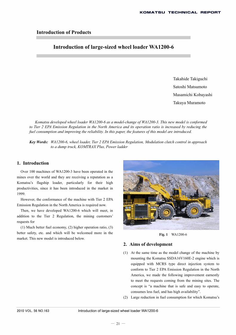
Over 100 machines of WA1200-3 have been operated in the mines over the world and they are receiving a reputation as a Komatsu’s flagship loader, particularly for their high productivities, since it has been introduced in the market in 1999.
However, the conformance of the machine with Tier 2 EPA Emission Regulation in the North America is required now.
Then, we have developed WA1200-6 which will meet, in addition to the Tier 2 Regulation, the mining customers’ requests for
(1) Much better fuel economy, (2) higher operation ratio, (3) better safety, etc. and which will be welcomed more in the market. This new model is introduced below.
Fig. 1 WA1200-6
2. Aims of development
(1) At the same time as the model change of the machine by mounting the Komatsu SSDA16V160E-2 engine which is equipped with MCRS type direct injection system to conform to Tier 2 EPA Emission Regulation in the North America, we made the following improvement earnestly to meet the requests coming from the mining sites. The concept is “a machine that is safe and easy to operate, consumes less fuel, and has high availability”.
(2) Large reduction in fuel consumption for which Komatsu’s
2010 VOL. 56 NO.163 Introduction of large-sized wheel loader WA1200-6
― 22 ―
leading technologies are concentrated (15% less than that of the former model)
• Employment of PNC control for work equipment pump • Variable control of steering pump • Active power-up control • Modulation clutch control during approach to dump truck • Automatic selection control between two modes of E-P of
engine (3) Increase of operation ratio by improvement of reliability
and durability • Reduction of engine speed (both rated speed and high idle
speed) • Increase of reserve power in cooling system (lowering
balance temperature) • Employment of hydraulic equipment having higher heat
resistance • KOMTRAX Plus • Engine oil reserve system (optional)
(4) Improvement of safety • 45-degree rear access step • Employment of walkthrough step over radiator grill • Emergency engine stop switch (operated on ground and
inside cab) • Guards to all drive shafts • Addition of thermal guard to muffler tail pipe and rotating
part guard • Power ladder (optional) • Floor for fire extinguisher tank (optional) • Service center (optional) • Seat for trainer (optional)
3. Main features
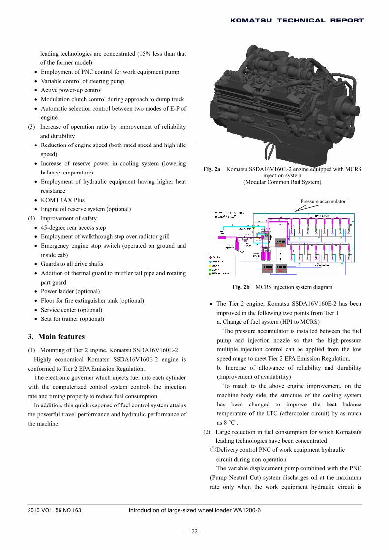
(1) Mounting of Tier 2 engine, Komatsu SSDA16V160E-2 Highly economical Komatsu SSDA16V160E-2 engine is
conformed to Tier 2 EPA Emission Regulation. The electronic governor which injects fuel into each cylinder
with the computerized control system controls the injection rate and timing properly to reduce fuel consumption.
In addition, this quick response of fuel control system attains the powerful travel performance and hydraulic performance of the machine.
Fig. 2a Komatsu SSDA16V160E-2 engine equipped with MCRS injection system
(Modular Common Rail System)
Fig. 2b MCRS injection system diagram
• The Tier 2 engine, Komatsu SSDA16V160E-2 has been improved in the following two points from Tier 1 a. Change of fuel system (HPI to MCRS)
The pressure accumulator is installed between the fuel pump and injection nozzle so that the high-pressure multiple injection control can be applied from the low speed range to meet Tier 2 EPA Emission Regulation. b. Increase of allowance of reliability and durability (Improvement of availability)
To match to the above engine improvement, on the machine body side, the structure of the cooling system has been changed to improve the heat balance temperature of the LTC (aftercooler circuit) by as much as 8 °C .
(2) Large reduction in fuel consumption for which Komatsu's leading technologies have been concentrated
①Delivery control PNC of work equipment hydraulic circuit during non-operation The variable displacement pump combined with the PNC
(Pump Neutral Cut) system discharges oil at the maximum rate only when the work equipment hydraulic circuit is
Pressure accumulator

2010 VOL. 56 NO.163 Introduction of large-sized wheel loader WA1200-6
― 23 ―
operated. While the work equipment hydraulic circuit is not
operated, the pump delivery is minimized to reduce the fuel consumption.
Fig. 3
②Employment of Hydrau Mind in steering hydraulic circuit (Pump delivery varies with lever operation distance *) The Hydrau Mind [variable displacement pump + load
sensing hydraulic system (CLSS)] has been employed in the steering hydraulic circuit as well.
The pump is controlled to deliver oil by the quantity required by the steering system.
The fuel consumption is reduced by minimizing the hydraulic loss, while the efficiency is increased and steering performance is maintained.
Fig. 4
*: Following delivery control is made. • When the steering wheel is operated quickly, the pump
delivery is maximized. • When the steering wheel is not operated or operated
slowly, the pump delivery is minimized. ③Active working system
This is a 2-mode system developed from the multi-stage hydraulic system on the previous model which has been well reputed. Either of the two modes (a. Powerful loading and b. Normal loading) can be selected with the active working switch according to the working load in digging ore, loading products, etc. In each mode, the oil flow for the work equipment hydraulic circuit is optimized for efficient work. During digging work, the horsepower consumption by the work equipment is controlled and the traction force (= drive force) is increased and the cycle time is shortened.
a. Powerful loading mode (Suitable for heavy digging work)
Automatic selection
Fig. 5a
* Controller judges “machine is digging” by cylinder pressure, gear speed, and other conditions and changes pump delivery

2010 VOL. 56 NO.163 Introduction of large-sized wheel loader WA1200-6
― 24 ―
Machine is digging ↓
Power is required but work equipment speed is not required
↓ Pump delivery is reduced
↓ Torque consumption by hydraulic equipment
(= work equipment) decreases ↓
Engine torque is given more to drive system ↓
Drive power increases and cycle time is shortened ↓
Production increases (for fuel consumption) ↓
Fuel economy is improved
b. Normal loading mode (Suitable for relatively light digging work)
Pump delivery is not reduced during digging or other work
Fig. 5b
④Control of approach to dump truck By controlling the modulation clutch automatically, the
forward travel speed is limited while the bucket raised speed is increased. Since the approach distance to the dump truck can be shortened with this control without braking operation, the loading operation can be made smoothly. In addition, the loss made by restraining the travel energy with the brake is reduced.
When transmission torque of modulation clutch is controlled
Fig. 6
During approach to dump truck ↓
Little drive force is required ↓
Torque transmitted to drive system is reduced by controlling modulation clutch
↓ Both of engine torque consumed by power train
and heat generated by brake during deceleration are reduced
↓ Fuel economy is improved
When transmission torque of modulation clutch is not controlled
Fig. 7
When approach to dump truck is not controlled ↓
Much heat is generated by brake during deceleration ↓
Fuel economy becomes bad

2010 VOL. 56 NO.163 Introduction of large-sized wheel loader WA1200-6
― 25 ―
⑤Automatic selection of E or P mode The engine has two modes of output performances, E
mode and P mode, either of which is selected automatically. The P mode is selected automatically only when the
machine digs or approaches a dump truck. With this control, not only the fuel consumption is reduced but also the engine load is reduced, thus the durability of the engine increases.
Fig. 8
E mode selected normally (when fuel
consumption is important)
P mode selected during digging or approaching to
dump truck
Fuel consumption and wear of engine are restrained while
securing necessary power by automatic selection
Fig. 9
With the above described ①Energy saving of the work equipment pump, ②Energy saving of the steering pump, ③Active power-up control, ④Modulation clutch control during approach to dump truck, and ⑤Automatic selection of engine performance E or P, the fuel consumption is reduced by 15% while performing the same work as that which was done by the former model.
Fuel consumption and Production when E-P automatic selection control is added
Results of fuel consumption and production tests
Pro
duct
ion
[ton/
h In
dex]
Previous model
Level when E-P automatic selection control is not added: Fuel consumption and Production
Fuel consumption [L/h: Index] Fig. 10
(3) Increase of operation ratio by improvement of reliability and durability
①Lowering engine speed a. Lowering engine speed
Rated speed: 1900 rpm down to 1800rpm High idle speed: 2050 rpm down to 1900 rpm
b. Setting and automatic selection of E mode performance and/or P mode performance With these improvements, the engine speed has been
decreased and the load has been reduced to improve the durability of the engine. (See the explanation of E and P automatic selection control in the above energy saving paragraphs)
②Installation of air-cooled type torque converter oil cooler as standard In addition to the water-cooled type torque converter oil
cooler, the air-cooled type is installed as standard. By lowering the torque converter oil temperature with this
cooler, the allowance against overheat of the system is increased largely, thus the reliability and durability of the seals and hoses of the whole system has been improved. Since the outside air is applied directly to the air-cooled oil cooler, it is not heated prior to the cooler and can cool the oil efficiently.

2010 VOL. 56 NO.163 Introduction of large-sized wheel loader WA1200-6
― 26 ―
Air flow which is not heated
Additional air-cooled torque converter oil cooler as standard Fig. 11
③Improvement of durability of hydraulic equipment Aim: To improve the reliability and durability of the
hydraulic equipment by preventing oil leakage from and efficiency reduction of the hydraulic equipment to lead to improvement of operation ratio of the machine
a. Change of the material of the O-rings and oil seals used in the hydraulic equipment to Hydrogenated nitrile rubber or Fluorine rubber
Upper temperature limit to use nitrile rubber is 100 °C
Upper temperature limit is increased to above 110 °C by
using hydrogenated nitrile rubber or fluorine rubber
Work equipment valve
Seal fitting portion of valve Fig. 12
SW pump STG pump
Fig. 13
b. Change of structure of cylinder rod seal Aim: To improve dust-resistance
Prevention of oil leakage caused by damage of rod seal on previous model
Old Subdust-seal Main dust seal
Rod packing
Buffer ring
SpacerMetallic scraper
Metallic scraper cannot scrape off all dust since it makes clearance
Fig. 14
Use of HNBR scraper ↓
Reduction of dust entry risk ↓
Prevention of damage of rod seal ↓
Improvement of durability of seal
New Subdust-seal Spacer
ScraperMain dust seal
Rod packing
Buffer ring
Sticking dust is scraped off withspecial lip (HNBR) to protect dustseal lip
Fig. 15
Fitting portion of cylinder seal
Fig. 16
④ Application of ICT (Information & Communication Technology) a. Employment of monitor panel of the latest design

2010 VOL. 56 NO.163 Introduction of large-sized wheel loader WA1200-6
― 27 ―
common to large-sized loaders The gauges and warning lamps important to know the
machine condition are arranged in front of an operator so that they can be checked easily even during operation. In addition, the LCD color graphic multi monitor is placed on the right side of the monitor panel to provide maintenance and failure information of the machine to help increase the operation ratio and to indicate the “production” and “fuel consumption information” that are production management information. (Fig. 17a) (Fig. 17b)
Fig. 17a Monitor panel
Fig. 17b Multi monitor
(Example of display of maintenance monitor)
b. Installation of KOMTRAX Plus (optional) The VHMS (Vehicle Health Monitoring System) is
installed as standard, which is used to know the machine condition and effective for preventive maintenance. This system is combined with KOMTRAX which has the functions of GPS and satellite communication terminal and is used as “KOMTRAX Plus” to control the machine in real time. With this system, the maintenance work and overhaul of the main components can be performed according to a schedule.
The VHMS terminal of this system collects and manages the trend data of temperature, pressure, etc. sensed by the sensors at various locations of the machine and the failure information transmission records analyzed
from those trend data in real time and displays them on the above described machine monitor as necessary.
In addition, it is possible to not only perform preventive maintenance for a specific machine but also analyze the operating conditions of all the Komatsu machines in each area and market trend statistically by downloading the data in the VHMS terminal to the KDW (KOMTRAX-Data Warehouse) server by using the communication function of KOMTRAX and watching them continuously.
server serverdata data
Modem Modem Modem
software software hardware hardware hardware
VHMS terminal VHMS terminal
Fig. 18 KOMTRAX Plus
⑤Extension of maintenance interval a. The air cleaner capacity is increased so that the
element maintenance interval can be extended even in mines where there is much dust.
Former model: φ14-inch air cleaner x 4 pcs. New model: φ15-inch air cleaner x 6 pcs. (standard)
b. “Oil reserve system *” is arranged to extend the engine oil replacement interval. (optional) * The external large-capacity tank is added to the
engine oil pan and the oil in it is circulated through the oil pan. As a result, the oil replacement interval is extended from 250 hours to 500 hours.
Fig. 19 Oil reserve system
選択
F1 F2 F3 F4 F5 F6
MAINTENANCE MONITOR 250 / 500h
250200
200
200
200
400
01 Change Corrosion Resister02 Change Fuel Filter
03 Change Engine Oil Filter
04 Change Engine Oil
05 Change Transmission Oil Filter
06 Change Brake Oil Filter

2010 VOL. 56 NO.163 Introduction of large-sized wheel loader WA1200-6
― 28 ―
(4) Improvement of safety and maintainability ①Change of slope angle of rear access step
The slope angle of the rear access step is changed from 60 degrees to 45 degrees to be gentler so that the operator can mount and dismount the machine more easily.
Fig. 20
②Facilitation of moving between right and left sides (Employment of walkthrough rear bumper) The walkthrough rear bumper is employed so that the
operator can smoothly move between the right and left sides to save maintenance time.
Can move between right and left sides on bumper Fig. 21
③Emergency engine stop switch The emergency engine stop switch is installed to four
places where the operator can stop the engine from the ground in an emergency and to one place inside the cab. (Fig. 22)
Fig. 22
④Protective covers are installed additionally to the rotary parts and hot parts for higher safety during maintenance.
i) Upper drive shaft cover (Fig. 23) ii) Alternator belt cover (Fig. 24) iii) Fan belt cover (Fig. 24) iv) Muffler tail pipe cover (Fig. 25)
Fig. 23
Alternator belt cover
Fan belt cover
Fig. 24
Fig. 25
⑤Addition of steps for maintenance Steps are added to the front frame for maintenance and
repair of the work equipment pin (Fig. 26). Steps are added to the rear frame for maintenance of the
engine and transmission (Fig. 27).

2010 VOL. 56 NO.163 Introduction of large-sized wheel loader WA1200-6
― 29 ―
Fig. 26 Fig. 27
⑥Power ladder (optional) The hydraulically-assisted power ladder is arranged as an
option. Since the ground and operator's seat are connected by the
45-degree ladder, the operator can mount and dismount in the walking posture and does not need to climb up or dismount backward. [Patent pending]
Drawn up and stored during travel or work. Drawn down to 400 mm above ground whenoperator mounts or dismounts
Fig. 28
⑦Service center (optional) The optional service center is arranged to be installed on
the side of the rear frame. If it is installed, the operator can replace or add all lubricants from the ground. (Maintenance time can be shortened largely)
Fig. 29
Uses of service center ports
1. Engine oil EVAC 2. Coolant EVAC 3. Torque converter coolant
EVAC 4. Transmission oil EVAC 5. Transmission oil
sampling 6. Hydraulic oil EVAC 7. Hydraulic oil pressure
release
8. Hydraulic oil sampling 9. Brake tank oil EVAC 10. Brake cooling oil EVAC11. Brake oil sampling 12. Refilling port for auto
grease tank 13. Auxiliary (Takeout to
outside)
⑧Trainer’s seat (optional)
The optional “trainer's seat” is arranged for an expert operator who will train a new operator. [Patent pending]
Multi monitor
Trainer’s seat
“Expert operator sits in the trainer’s seat and teaches a new operator efficient operation skill, explaining the horsepower distribution to the work equipment and wheels, etc. displayed on the multi monitor”
Fig. 30
4. Conclusion
While the development plan of this machine was being made, the injection system of the Cummins engine was changed from HPI to MCRS, and the rated engine speed and high idle speed were changed to improve the durability of the engine just before starting the mass production.
Fortunately, since we had employed the energy saving control to compensate the increase of the fuel consumption

2010 VOL. 56 NO.163 Introduction of large-sized wheel loader WA1200-6
― 30 ―
caused by the engine modification to meet the Tier 2 Regulation, that control also increased the production, and then we succeeded in reducing the engine speed while keeping the improved production at the same level as that of the previous model. (23 patents, including the fuel consumption reducing technology, pending)
As the result, the engine durability was improved and the fuel economy was improved largely as well.
We regret that the development was delayed against the schedule.
The largest factor of the delay was the delay in establishing the durability of the injection system. To prevent such delay in the future, we should match the manufacturing schedule of the prototype machine to the completion of the main components in the step <b>.
Introduction of the writers
Takahide Takiguchi Entered Komatsu in 1986. Currently belongs to Construction Equipment Technical Center 2, Development Division
Satoshi Matsumoto Entered Komatsu in 1997. Currently belongs to Quality Assurance Department, CHINA Development Division, Komatsu (China) Ltd.
Masamichi Kobayashi Entered Komatsu in 2006. Currently belongs to Construction Equipment Technical Center 2, Development Division
Takuya Muramoto Entered Komatsu in 2001. Currently belongs to Construction Equipment Technical Center 2, Development Division
[A few words from writers] The main purpose of this development was to conform to the
machine to the Tier 2 Regulation. However, the costs of the engine and chassis had to be increased to attain it. To keep the O & O cost acceptable by customers, we decided to compensate the increase of the costs with the improvement of the fuel economy.
However, there was a restriction that the “main components of the new large-sized machine had to be interchangeable with those of the previous model”.
Then, we added the following control function as described above. • Control of hydraulic pump delivery
Since the work equipment pump and steering pump of WA1200-3 are piston pumps, which control the delivery partially, new control function was able to be added easily.
• Control of approach operation to dump truck WA600-6 has a system to decrease the transmission torque of the modulation clutch when the brake is applied. We applied this philosophy (with different mechanism).
• Active working system The active working system employed on WA600 thru 900-3 which has been highly evaluated was developed for and installed on WA1200-6.
• E and P automatic selection control The required horsepower for each working mode was reviewed, and efficient use of the engine horsepower and reduction of the engine load (improvement of durability) were targeted simultaneously. We had the cooperation of many staffs of System Development
Center and Hydraulic Equipment Development Center in establishing the above control functions, and the fuel consumption was reduced 15% as a result.
Whenever we moved the prototype machine for performance test, practical operation test, and EMC test we transported, disassembled and reassembled the machine. We did them eleven times in total. We succeeded in the development of the machine with the cooperation of many staffs who were involved in the project.
We express our thanks to those who gave us their cooperation with us at this time of the development.