introduction: joe houston, hra, spie lessons learned...
TRANSCRIPT

Introduction: Joe Houston, HRA, SPIE Lessons Learned 14 August 2012
Joe Houston began his adventure in optics when he was the first and only undergraduate in Astronomy at the University of Texas, graduating in 1956.
He received a Regular Army commission in the Corps of Engineers. During his five years of active duty, he served as a company commander in the U.S. and group aviation officer in Korea. While stationed at Ft. Ord, CA, he taught the first astronomy course offered at Monterey Peninsula College in 1961. He fulfilled his military obligation with the rank of Captain and designation of Senior Army Aviator.
Joe then began his career in industry on the east coast at Perkin-Elmer in Connecticut followed by Itek, Diffraction Limited and Kollmorgen in Massachusetts. While in the Boston area he earned a Masters Degree in Engineering Management from Northeastern University. For recreation he continued skydiving, flying and learned to ski and ice skate.
Returning to the west coast was a decision made in the winter of 1972-73 during one of the worst snowstorms in western Massachusetts history. The call from the balmy San Francisco Bay area to become a vice president of Itek’s Applied Technology Division was an irresistible offer.

Completing his “grand tour” in industry in 1981, Joe elected “to do it himself” and formed Houston Research Associates. In subsequent years he founded Houston Technology International, Inc. and SoftCam, Inc. to meet the specific needs of his clients including law enforcement and the medical community.
As a consultant to date, Joe has served over 200 companies, 3 research institutes, 3 universities, 6 government agencies and the Office of the Deputy Under-Secretary of Defense for Research and Advanced Technology.
In addition to over 200 technical publications he served as Associate Editor for SPIE and edited the Optical Systems Manufacturing Technology column for Optical Engineering.
Joe’s professional society memberships include past member of the Optical Society of America where he served as President of the New England Section and co-founded the Society’s Optical Fabrication and Testing Group. He joined SPIE in 1974 as Program Chairman. Subsequently he served as President in 1978-79 and was elected a Fellow. Additionally he was retained as the Society’s Advanced Technology Advisor and served as the first chairman of the Technology Transfer Committee. During the 1990s, he was co-founder and Executive Director of the Forum for Military applications of Directed Energy. He is an active member of the Naval Submarine League and a past member of the Electronic Warfare Association of Old Crows.
Patent awards include the Laser Unequal Path Interferometer, Fingerprint Identification Device and the TIME Tool.
He was the recipient of the SPIE Goddard and Presidents Awards as well as the U. S. Army’s Outstanding Civilian Service Medal for significant contributions to the U. S. Army Intelligence and Security Command.

SLIDE 1
Here in Austin, Texas, was the formal beginning of my Adventure in Optics.
NO, that is not my great grandson at the eyepiece of the University’s 9-1/2 inch telescope as illustrated in this clipping from the Austin Statesman newspaper circa 1954.
After my years as an Astronomy major at the University of Texas in Austin, followed by 5 years in the Army, followed by 20 years in the optical industry, this brochure shown on the left, was prepared for SPIE, San Diego 1981 – over 31 years ago -when I decided to become a consultant.
The art work depicts a Cooke triplet transforming Science into Technology in an M. C. Escher black and white graphic.

SLIDE 2
My revelations tonight will highlight 50 years of this optical journey. As a framework, I will use unique events coupled with acknowledgment to my many mentors and colleagues who helped along the way. You may see some familiar faces. We are honored by those who are present tonight.

SLIDE 3
My first experience with large optics occurred in the spring of 1956 at the McDonald Observatory in west Texas. You see Mt. Locke in the distance and below to the left, the Otto Struve 82-inch observatory and the 107-inch Harlan J. Smith observatory. Altitude is 6,800 feet. Below and to the right is a view, inside the dome housing the 82-inch Struve telescope structure. Building the 82-inch observatory and telescope began in 1933; the observatory was dedicated in 1939. This site in the Davis Mountains was selected for its large percentage of clear nights. Often, astronomers working there can see the Southern Cross.

SLIDE 4
My senior project was Binary Stars. My advisor was Dr. George van Biesbroeck of the University of Chicago. One of my additional duties “as assigned” during my time on Mt. Locke was to hold Dr. van B by his belt as he stood on the railing, leaning out at a 45 degree angle, while changing glass plates at prime focus.
It was a powerful learning experience in many areas. It led me to the conclusion so humorously portrayed in a cartoon showing two astronomers lounging and conversing outside an observatory dome in the starlight. The cartoon was published by the Optical Society of America in 1962. The caption, quoting one Astronomer saying to the other: “if there’s one thing I’ve learned about the Universe, it’s the fact that there’s no money in Astronomy”.

Concurrently with the draft breathing down my neck, I elected to pursue a commission in the Army Corps of Engineers with the expectation of becoming a rocket scientist at Redstone Arsenal in Huntsville, Alabama. Instead, the Army sent me to Ranger School, then to Jump School, then to Jumpmaster training, then to Fixed-Wing Flight School, then to Instrument Flight School, then to Helicopter Flight School, and finally to Korea! What is it they say? “Life is what happens when you’re making other plans”. Presently, I was on assignment with a Strategic Army Corps Construction Battalion at Ft. Ord, CA, that was slated to deploy to Europe with only a 24-hour notice. So finally, after 5 years of moving further and further from Redstone Arsenal, I felt that I had drawn a “blank”.
SLIDE 5

Despairing, I resigned my commission in the Regular Army to work at Perkin-Elmer in Norwalk, CT.
SLIDE 6
EUREKA! I couldn’t believe that I had hit the jackpot with my first job assignment back in Astronomy. This time I would become project engineer on the Stratoscope II balloon-borne telescope’s 36-inch, primary mirror, reporting to Dr. Martin Schwarzchild of Princeton University and Dr. Rod Scott, Vice-President and Chief Scientist of Perkin-Elmer.

Stratoscope II which was designed to explore the heavens from a balloon-borne platform some 80,000 feet above the earth’s surface, established the science and technology underpinning for the Hubble Space Telescope.
Martin was the Stratoscope II Program Manager for Dr. Lyman Spitzer at Princeton, the driving force behind astronomical instruments in space, and Perkin-Elmer’s customer for this “sky-breaking” activity.

SLIDE 7
Again, NO, that is not my grandson placing the 36-inch Stratoscope II primary mirror into Perkin-Elmer’s first refrigerated, vacuum chamber during one of the dozens of scatterplate interferometer, null-lens tests in a simulated operational environment.
At the left, is a list of factors that highlight this period of R&D.

SLIDE 8
Little did I know that after all the 90 hour work weeks over a 2 year period, this mirror would help achieve all of the project science objectives then, courtesy of Princeton University, find its way to the Monterey Peninsula in California. (Ironically, I was stationed there when I resigned my commission in the Army to work for Perkin-Elmer, and now reside there in Pacific Grove). Things sometimes come full circle.
The fortunate recipients of this gift were a group of young Astronomers from Case Western Reserve University. With this gift they established the Monterey Institute for Research in

Astronomy. In terms of a serious instrument, this 36-inch mirror, certified as the most perfect mirror of its size, more than satisfied their requirements. As Dr. Cynthia Irvine, President of MIRA and one of MIRA’s founders said,” I thought I’d died and gone to the Heavens.”
In addition to supporting world class research projects at MIRA, the Observatory known as the Oliver Observing Station, offers public viewing on scheduled, dark-of-the-moon nights. These public nights include an invitation to families and ATMers to bring their own telescopes and enjoy an evening Star Party.
Although the Oliver Observing Station is only 25 miles from downtown Carmel, prepare for a dusty, bumpy, 4-wheel, 1-1/2 hour, out-back journey to the top of Chew’s Ridge in Big Sur.
Come join us!
SLIDE 9
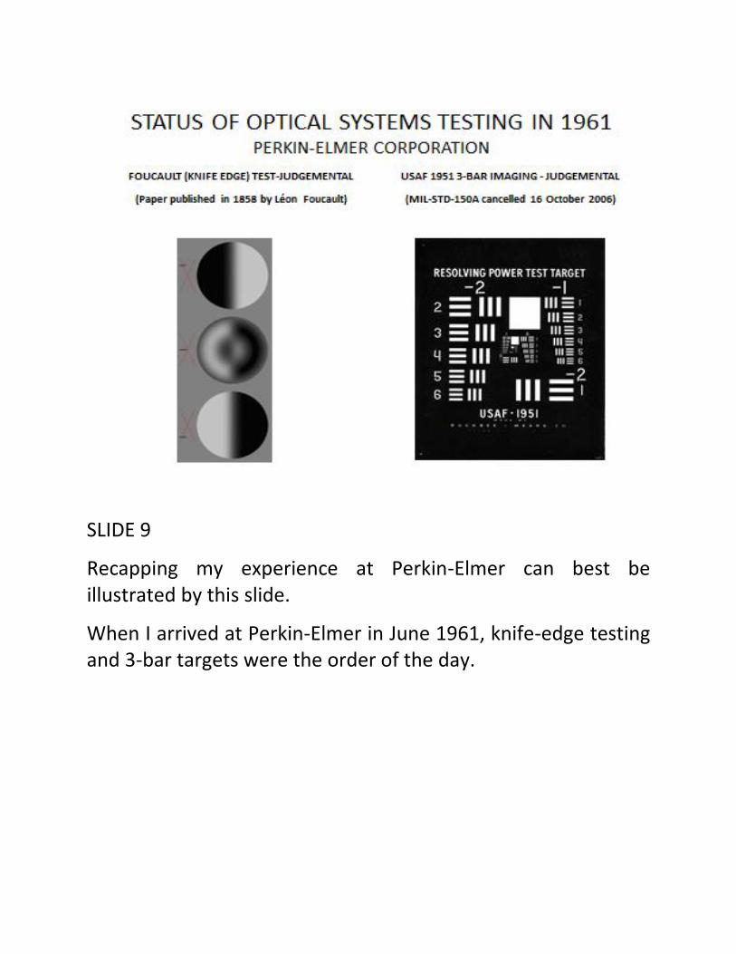
Recapping my experience at Perkin-Elmer can best be illustrated by this slide.
When I arrived at Perkin-Elmer in June 1961, knife-edge testing and 3-bar targets were the order of the day.

SLIDE 10
This familiar layout depicts the same technology that I used in 1948 to grind, polish and figure my first 8-inch mirror, using a pyrex blank acquired in kit form from Precision Optical Supply Company through an ad in Sky & Telescope.

SLIDE 11
When I departed for Itek in January 1964, thanks to the efforts of Martin Schwarzchild and Rod Scott, P-E had attained a preeminent position in optical testing by integrating the development of scatterplate interferometry with Offner-type null lenses.
SLIDE 12
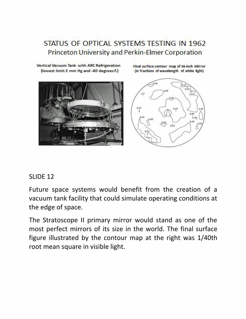
Future space systems would benefit from the creation of a vacuum tank facility that could simulate operating conditions at the edge of space.
The Stratoscope II primary mirror would stand as one of the most perfect mirrors of its size in the world. The final surface figure illustrated by the contour map at the right was 1/40th root mean square in visible light.

SLIDE 13
On my arrival at Itek, Dow Smith tasked me with the job of upgrading both the large and the small optical shops with new test equipment and new methods. This included testing not only the Corona satellite lenses but also large optical windows that were to be installed in reconnaissance aircraft operated by the USAF and the CIA. There were several projects that were in jeopardy of overruns and late deliveries.

SLIDE 14
Surprisingly, I discovered that the state-of-the-art in optical testing at Itek was just as I had found it at P-E in June 1961. It was still the Foucault knife-edge for components and 3-bar targets for systems.
Immediately, I put my P-E experience to use. Just as everything was going so well, a problem arose!

SLIDE 15
Alas, a large mirror with a very large hole in it appeared on the scene. Result: the scatterplate interferometer had no central, contiguous surface on which to place a reference patch. Testing this mirror with a scatterplate interferometer meant that the contrast on the side opposite a reference beam would be near zero and make fringe analysis very difficult. Enter the laser unequal path interferometer also known as the LUPI.
After several weeks and using a newly developed Perkin-Elmer helium-neon (gas) laser with optical cubes, with and without spherical surfaces, pellicle beam splitters, beam splitters at Brewster’s angle as well as at 45 degrees, and altering the

reflectivity of various surfaces, I finally worked out a plan for a highly flexible modified Twyman-Green interferometer designed for the optical shop. There were several challenges including being able to rapidly change the system f-number configuration, the requirement for very large path disparity, i.e. tens of meters, the importance of conveniently matching the two beam intensities as well as optimizing fringe visibility, and last but not least, eliminating spurious reflections. First I expanded and re-collimated the gas laser beam. Then I used a small, high quality flat in one leg of the interferometer configuration, reflecting the beam off a Brewster’s angle beam splitter having a high efficiency, anti-reflection coating on its opposite surface. Simultaneously, I passed the expanded, well-collimated beam from the laser through the beam splitter into a high quality microscope objective (call it a diverger) to get interference fringes over large mirrors at great distances from the test setup. The small flat was arranged to be “tuned” back and forth on a trombone-like slide to maximize fringe contrast. The diverger could be designed and built economically for special jobs. Also, there was the convenience of selecting from a myriad of high quality microscope objectives thus providing the optical shop with a wide range of f-numbers. Exchanging divergers to fit unique components or systems could be accomplished in a matter of minutes. The LUPI could also be combined with null lenses for testing aspherics.
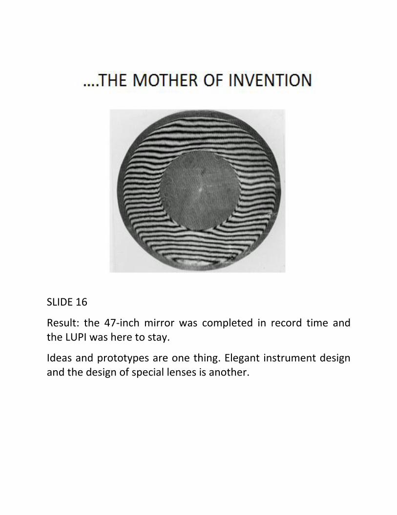
SLIDE 16
Result: the 47-inch mirror was completed in record time and the LUPI was here to stay.
Ideas and prototypes are one thing. Elegant instrument design and the design of special lenses is another.

SLIDE 17
John Buccini, shown on the right, a gifted mechanical engineer, was responsible for turning my drawings into an elegantly designed instrument. He built and assembled the first LUPI for optical shop use. He then went on to refine and build over 250 more LUPIs, operating from his headquarters, Buccini Instrument Company, now in Wilmington, NC . Pat O’Neill, an outstanding lens designer, designed the first, very fast diverger for the f/1.7 mirror and later designed an even faster diverger to operate at f/0.7.

It is interesting to note that the first LUPI conceived, designed and built to be sold as an Itek standard product was acquired by Dr. Aden Meinel, Director for the newly established Optical Sciences Center at the University of Arizona in Tucson. He was in the process of creating a world class program for training the future generation of optical engineers including many bright officers in the U. S. Air Force. Previously, I had worked with Aden when he consulted for Perkin-Elmer in the early 1960s. Additional product style LUPIs and null lens combinations would be delivered to Aerojet General and Perkin-Elmer after this inaugural success.
On the left is pictured one of many vacuum tanks installed at Itek. This one allows for testing large mirrors in orientations ranging from vertical to horizontal in order to understand the effects of gravity on mirrors in a variety of special mirror mounts.
From 1966 to 1969, Itek’s Optical Systems Division purchased more than a dozen P-E lasers, used thousands of boxes of Polaroid film for recording interferograms and set the stage for the interferometer revolution that would come in the 1970s.
Vacuum tilt test and vertical vacuum test tanks soon replaced Sonoduct tubes in long test tunnels at Itek and became part of Itek’s rapid growth in the mid-1960s, adding a new J-wing to the existing building. Turn-around times on Itek’s optical machines were reduced by an order of magnitude. Surface figure improved as a result of the optician knowing exactly
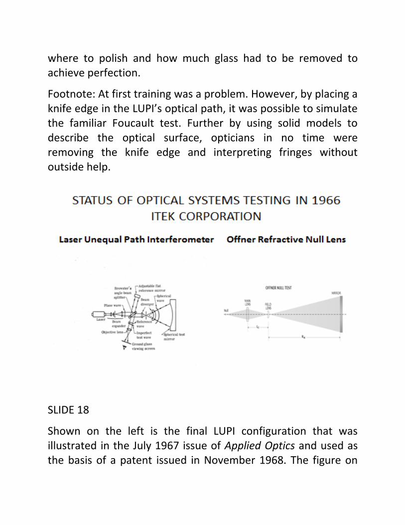
where to polish and how much glass had to be removed to achieve perfection.
Footnote: At first training was a problem. However, by placing a knife edge in the LUPI’s optical path, it was possible to simulate the familiar Foucault test. Further by using solid models to describe the optical surface, opticians in no time were removing the knife edge and interpreting fringes without outside help.
SLIDE 18
Shown on the left is the final LUPI configuration that was illustrated in the July 1967 issue of Applied Optics and used as the basis of a patent issued in November 1968. The figure on
the right shows the familiar optical paths of a refracting Offner-type null lens.
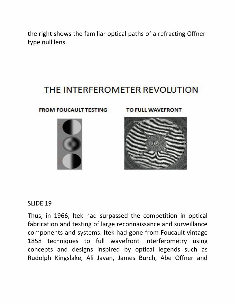
SLIDE 19
Thus, in 1966, Itek had surpassed the competition in optical fabrication and testing of large reconnaissance and surveillance components and systems. Itek had gone from Foucault vintage 1858 techniques to full wavefront interferometry using concepts and designs inspired by optical legends such as Rudolph Kingslake, Ali Javan, James Burch, Abe Offner and

Martin Schwarzchild. In the optical shop this was referred to “the interferometer revolution.”
SLIDE 20
Illustrated here are a few, selected milestones of the revolution. Note the significance of the gas laser.

SLIDE 21
The revolution had a number of profound effects on the industry and the military-industrial complex in general. Several of the most important results are listed here.

SLIDE 22
An example of exploiting the LUPI to create surface contour maps is shown in this pair of pictures. Following a paper I gave at the Miami meeting of the Optical Society of America in 1969, Itek began to implement a variety of “surface figuring” algorithms for the purpose of automating shop tools. Dr. Wiktor Rupp and his associate, Ron Aspen, performed some pioneering demonstrations of things to come.

SLIDE 23
Although an error in using P-E’s all reflecting null lens produced a faulty primary mirror for the Hubble Space Telescope project, interferometry salvaged the situation by not only providing hard, quantitative evidence regarding the error but also enabled the qualification of a “fix” known as the Corrective Optics Space Telescope Axial Replacement (COSTAR) system.
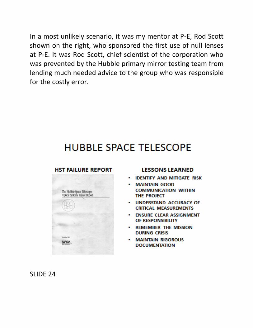
In a most unlikely scenario, it was my mentor at P-E, Rod Scott shown on the right, who sponsored the first use of null lenses at P-E. It was Rod Scott, chief scientist of the corporation who was prevented by the Hubble primary mirror testing team from lending much needed advice to the group who was responsible for the costly error.
SLIDE 24

The history of this extremely costly error is contained in the November 1990 HST Failure Report. This report was generated by a blue ribbon commission which was chaired by Dr. Lew Allen. I will talk more about Dr. Allen later in this presentation.
One of the best reports on this subject was published in the Hartford (CT) Courant newspaper during early August 1980; it won the Pulitzer Prize for Explanatory Journalism.
SLIDE 25
Lately, as a result of lack of interferometer training in the user and operator community lately, a new fringe interpretative
technique has been developed. In an optical workshop reception at the University of Central Florida, Delmar Haddock, a Navy customer, exclaimed that there has to be a way to communicate with the un-initiated government community who could not tell a fringe from a frown. Jim Harvey and I discussed the advantage of full wavefront interferometry in situ using large autocollimating flats with the LUPI. I had been using interferometers in the field for over 40 years thus, the data about installed instruments was readily available to those users and operators. Meanwhile, Optical Research Associates had developed software that converted theoretical lens design results into realistic-styled but simulated images so that the customer could get a feel for the design before buying it. In our case, we needed to know when the fielded telescope had deteriorated to the point of being replaced or requiring maintenance. Occasionally, we wanted the user to make a call on the quality of the image prior to assigning the telescope to a specific launch mission at Cape Kennedy.

SLIDE 26
Everyone agreed “it’s about time.” Thus the name TIME Tool which stands for Telescope Interferometric Maintenance and Evaluation. For further details, see Jim Harvey. The software is available to anyone with a perceived need through the offices of Joe Salg who is located in the Damewood Optical Maintenance Laboratory at Patrick AFB, FL.
SLIDE 27
Since 1950, the United States Air Force and the CIA have always had an edge in reconnaissance and surveillance systems through their “black budgets”. Their requirements attract the best and brightest practitioners of the art. It also provides the R&D community with a shield from outside interference. Carl Duckett, the Deputy Director for Science & Technology at the CIA from 1966 to 1976 and one of my many mentors, was a master at exploiting advances in the R&D community, while at the same time shielding his teams from outside interference. A contrasting example was a young engineer at General Dynamics in Fort Worth, TX, who was responsible for the F-111 flight test program. He took time out from his excruciatingly hectic

schedule to give me a tour of the factory….on bicycles! As I was leaving, he said (quote): “we have had 123 change orders from non-technical types in the Pentagon. At this rate, I don’t know how we can complete the job.” The following Sunday he died of a massive coronary!
SLIDE 28
Brigadier General George W. Goddard has been a role model for all engaged in Airborne Reconnaissance. I spent an entire evening listening to his stories (and lessons learned) about subjects ranging from Sherman Fairchild, the hard-charging

industrialist, to Milton Caniff, the cartoonist. We talked into the wee hours of the morning during his visit to San Diego and his attendance at SPIE Symposium in 1976. It was a rare opportunity to engage in one of the most fascinating dialogs imaginable. Featured on the left is the General, in uniform, with Duncan MacDonald, chairman of the Physics Department at Boston University. In 1946, Dr. Macdonald established the United States Air Force Optical Research Program. Dr. MacDonald left the University in 1957 taking the Air Force Program with him, to establish the Itek Corporation.
On the right, a copy of the cover of BG Goddard’s classic, Overview, recommended reading for anyone interested in following his footsteps through time; it is a history of the trials, tribulations and success stories of aerial photography in the United States from 1917 to 1969.
SLIDE 29
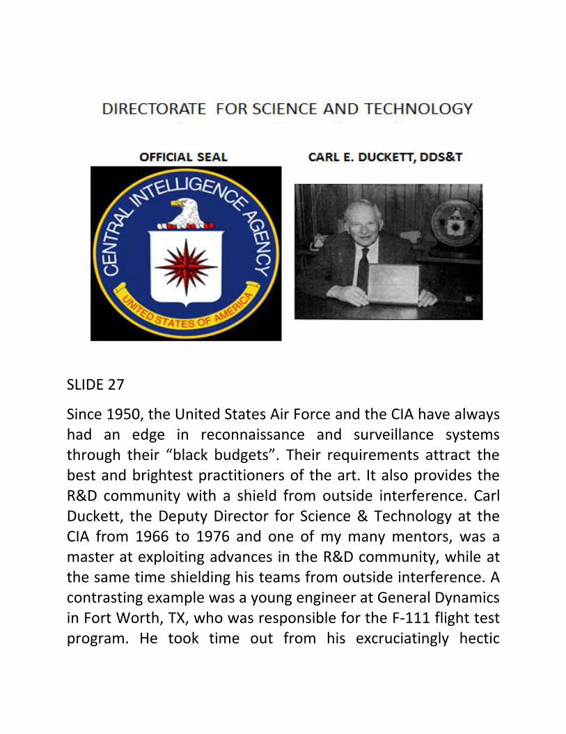
Another example of the success enjoyed by leaders and pioneers using “black budgets” is Kelly Johnson. In his famous Skunk Works, development of the U-2 was accomplished in 9 months. The SR-71 set altitude and speed records and raised the airborne reconnaissance bar. Kelly tested his birds out of a base that “never existed”, Area 51. Today we know that Area 51 is co-located with the Nevada (Nuclear) Test Site, 82 miles NNE of Las Vegas. Carl Duckett worked closely with Kelly and his team, using the U-2 and SR-71 as platforms for advanced optical sensors. For many years, SPIE hosted the “Airborne Recce” Symposium, published its unclassified papers and provided many of its authors. My role was to insure that the sessions were held in the appropriate venue. On several
occasions, I was privileged to visit the Skunk Works, meet with Kelly and his engineers while providing technical information on recent innovations in signals intelligence (SIGINT) and image intelligence (IMINT) hardware.
SLIDE 30
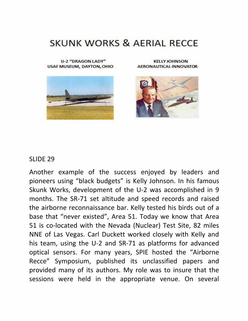
Progress requires great vision and great leadership. Theo von Karman authored the seminal report “Towards New Horizons” laying out the goals and objectives of the US Space program.

General Lew Allen, Corona pioneer and former Chief of Staff of the U.S. Air Force, exerted outstanding leadership in the Air Force and established strong ties with the CIA. After retiring from the USAF, Dr. Allen returned to JPL as its sixth director in 1982 and served there until 1990. I was fortunate to have him as a friend and counselor, always ready to support an ambitious cause and gracious in his demeanor to young scientists and engineers. He was an inspiration to all who worked with him on problems in space optics.
SLIDE 31

The Corona program has been the subject of several documentaries and many books including the book about Itek, entitled “Spy Capitalism.” Jim Baker was the epitome of the consummate optical scientist and engineer….a brilliant designer, innovator and optician. He was a pioneer in automatic lens design, airborne and space borne reconnaissance as well as astronomical telescopes. At Perkin-Elmer and later at Itek, he was always available to discuss with me the latest breakthroughs in optical fabrication and testing. He was an advocate of the LUPI. He never lost his love of “the shop.”
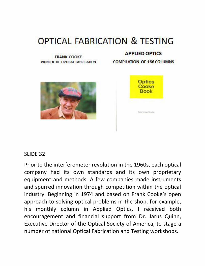
SLIDE 32
Prior to the interferometer revolution in the 1960s, each optical company had its own standards and its own proprietary equipment and methods. A few companies made instruments and spurred innovation through competition within the optical industry. Beginning in 1974 and based on Frank Cooke’s open approach to solving optical problems in the shop, for example, his monthly column in Applied Optics, I received both encouragement and financial support from Dr. Jarus Quinn, Executive Director of the Optical Society of America, to stage a number of national Optical Fabrication and Testing workshops.
On the left, is a picture of the jovial Frank Cooke, and on the right, a copy of his famous “Cooke Book”.
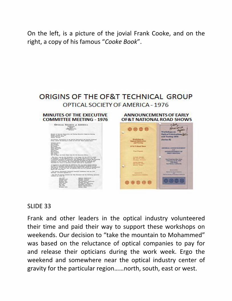
SLIDE 33
Frank and other leaders in the optical industry volunteered their time and paid their way to support these workshops on weekends. Our decision to “take the mountain to Mohammed” was based on the reluctance of optical companies to pay for and release their opticians during the work week. Ergo the weekend and somewhere near the optical industry center of gravity for the particular region……north, south, east or west.

This activity which was encouraged by Jarus Quinn and the OSA Executive Committee was the origin of the current OF&T Technical Group. In 1976, I asked Jarus if the OSA would support a new technical group within the Technical Council and after polling the Board, he said yes!
On the left are the minutes of the first meeting held on 18 October 1976 in Tucson, AZ.
On the right are two examples of OF&T “flyers”, advertising the road show in Chicago/Dallas and San Mateo, CA.
SLIDE 34

The positive results of these experiences became a national movement; the outcomes depicted in this slide were manifold. Foremost, and above all else, the commitment made by leaders in the optical industry created a formal mechanism for convening national and international conferences on OF&T. These conferences continue to the present day.
SLIDE 35
Frank Cooke often said: “A bright light under a bush soon goes out”.
Such wisdom shared is a gift to all opticians and optical engineers.

SLIDE 36
Optics has a way of introducing its followers into all sorts of interesting situations. Take the Nevada Test Site. Earlier in this talk I mentioned the nuclear test site and its neighbor, Area 51. Shown on the left of this slide is an aerial view of the pock-marked surface of the site resulting from dozens of underground nuclear explosions. On several visits to NTS I was

privileged to discuss both optical as well as electromagnetic pulse (EMP) phenomenology with the staff at the EG&G facility located in nearby Las Vegas.
As a visitor one quickly discovers, EG&G is “THE PORTAL” to NTS. Founded by Dr. Harold Edgerton, aka “Papa Flash” to his friends in Boston, EG&G wrote the book on “black budgets” while supporting the Atomic Energy Commission in the late 1940s and early 1950s.
In addition to assisting Los Alamos and Livermore Labs with characterizing smaller and more powerful nuclear weapons, NTS also performs tests on a variety of targets including optical surfaces. In one case, hundreds of different optical materials (gumdrops) were polished, figured and characterized to fractions of a wavelength of visible light. They were mounted in racks to be exposed to radiation from a nuclear blast in this tunnel. Unfortunately, in this case, special large doors lining the tunnel failed to close quickly enough after the samples were irradiated and the result was a “fused” work of art. Accidents do happen.
AND NOW FOR SOMETHING ENTIRELY DIFFERENT

SLIDE 37
Ideas about submarines have been around since 1580. Navy periscopes have been around since 1854. The latest developments in periscope technology have occurred as a result of optical technology innovation that includes digital imaging, infrared systems and integrated electronic systems.
My experience with Navy periscopes began in 1969 with a competitive development between the incumbent Kollmorgen, since 1916, and Itek Corporation. Itek had its image motion stabilization technology and offered innovative lens design and
special fabrication techniques. Kollmorgen on the other hand, proposed a LOS stabilization system based on a servo-driven, gyro stabilized head prism. As chief optical engineer on the Itek version of the Type 18, I was invited to participate in mid-Atlantic sea trials aboard the USS-607 “Dace”.
The Dace was classified as a fast attack, nuclear submarine. Its stated test depth was 2,000 feet and its stated speed was 28 knots submerged. It was decommissioned on 2 December 1988. In service in 1970, it provided first class accommodations with one proviso. There are a limited number of bunks for its complement of 14 officers and 105 enlisted men. Oftentimes there are “riders” such as yours truly and individuals from the intelligence community referred to by the crew as “spooks”. However, since watches are regulated to 4 hours, those crew members and visitors who are not on duty must “hot bunk”, i.e., share the bunk with those who are. Dropping off to sleep after a busy watch is peaceful with the seawater passing just inches from one’s ear. However, space is at a premium. The bunks are arranged in stacks with minimum head room. There is no way to sit up suddenly without getting a severe headache. Diving to test depth is usually illustrated to the neophytes by stretching a rope from one side of the boat to the other. As the outside pressure builds up the rope sags markedly. It doesn’t take a rocket scientist to understand that the hull is beginning to collapse.
Here then is a typical diving scenario. The video has been embedded. The sounds you hear are typical of a normal dive and the crew spirit is typical of the average “submariner”.
SLIDE 38
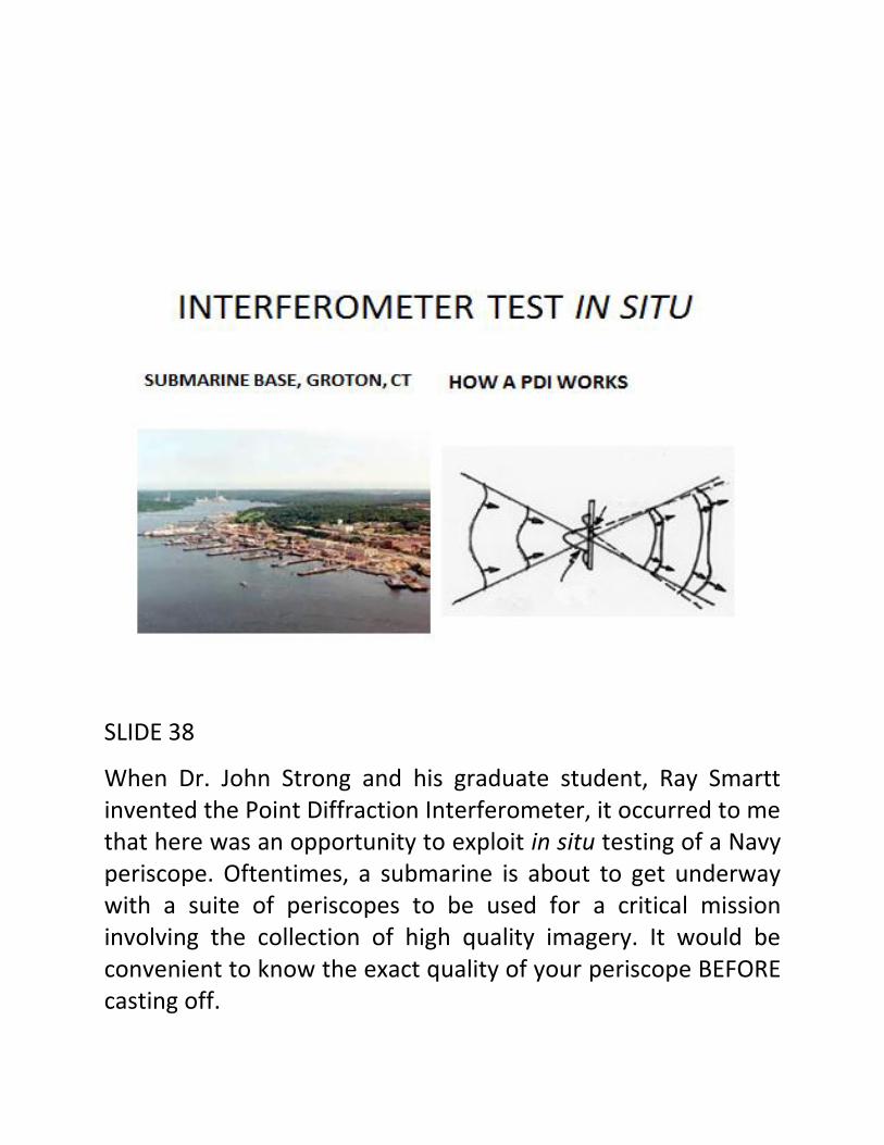
When Dr. John Strong and his graduate student, Ray Smartt invented the Point Diffraction Interferometer, it occurred to me that here was an opportunity to exploit in situ testing of a Navy periscope. Oftentimes, a submarine is about to get underway with a suite of periscopes to be used for a critical mission involving the collection of high quality imagery. It would be convenient to know the exact quality of your periscope BEFORE casting off.
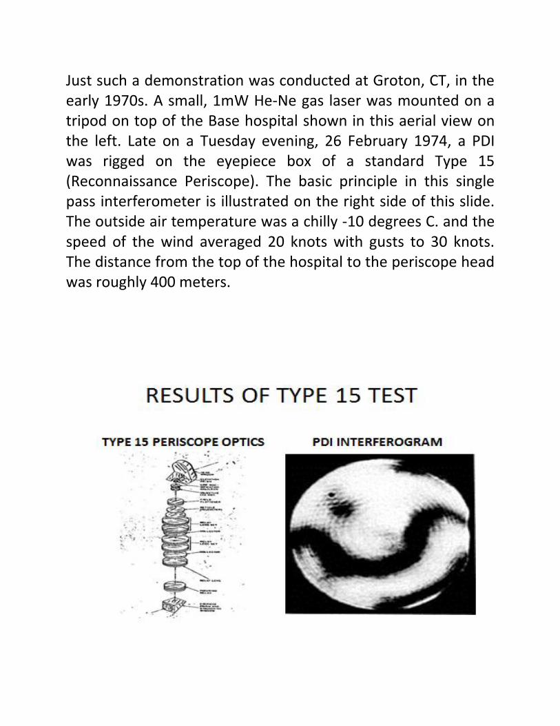
Just such a demonstration was conducted at Groton, CT, in the early 1970s. A small, 1mW He-Ne gas laser was mounted on a tripod on top of the Base hospital shown in this aerial view on the left. Late on a Tuesday evening, 26 February 1974, a PDI was rigged on the eyepiece box of a standard Type 15 (Reconnaissance Periscope). The basic principle in this single pass interferometer is illustrated on the right side of this slide. The outside air temperature was a chilly -10 degrees C. and the speed of the wind averaged 20 knots with gusts to 30 knots. The distance from the top of the hospital to the periscope head was roughly 400 meters.
SLIDE 39
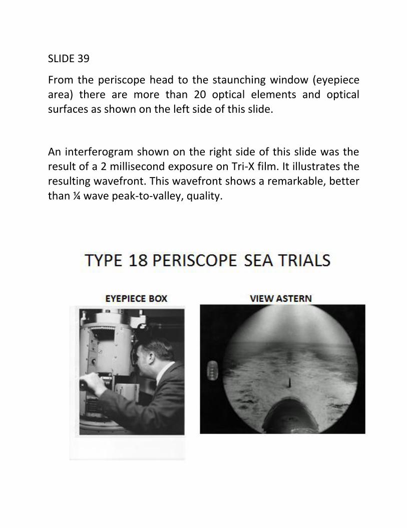
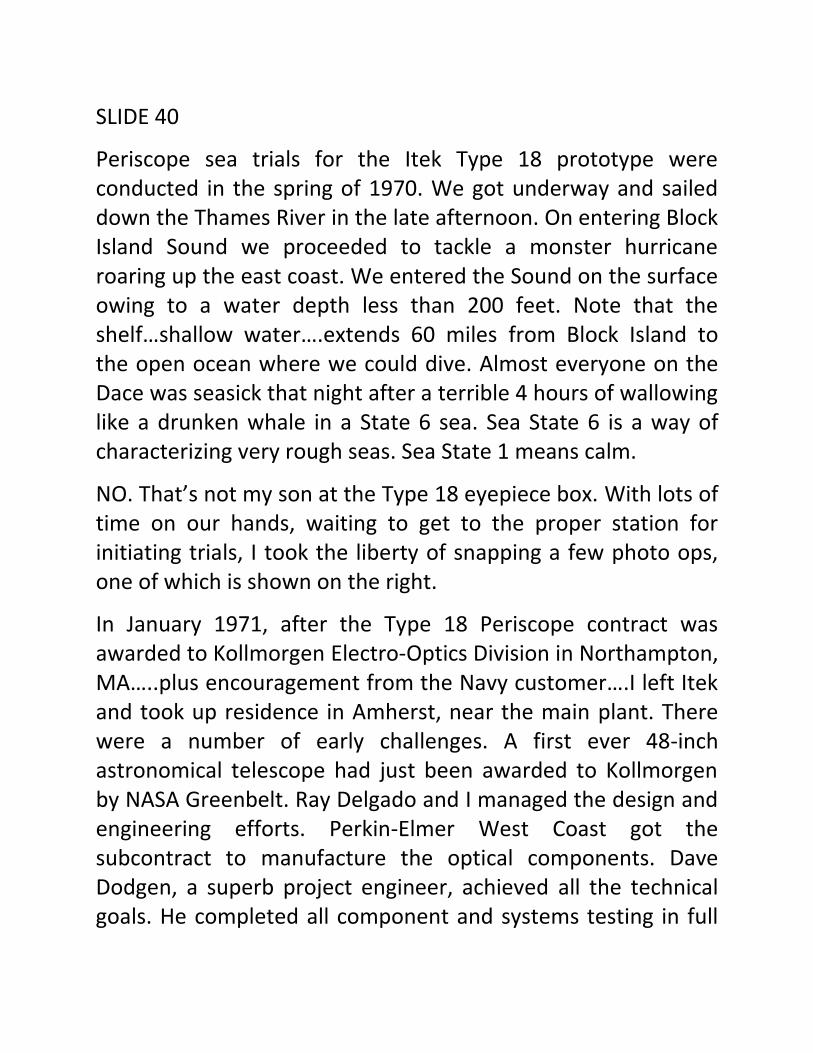
From the periscope head to the staunching window (eyepiece area) there are more than 20 optical elements and optical surfaces as shown on the left side of this slide.
An interferogram shown on the right side of this slide was the result of a 2 millisecond exposure on Tri-X film. It illustrates the resulting wavefront. This wavefront shows a remarkable, better than ¼ wave peak-to-valley, quality.
SLIDE 40
Periscope sea trials for the Itek Type 18 prototype were conducted in the spring of 1970. We got underway and sailed down the Thames River in the late afternoon. On entering Block Island Sound we proceeded to tackle a monster hurricane roaring up the east coast. We entered the Sound on the surface owing to a water depth less than 200 feet. Note that the shelf…shallow water….extends 60 miles from Block Island to the open ocean where we could dive. Almost everyone on the Dace was seasick that night after a terrible 4 hours of wallowing like a drunken whale in a State 6 sea. Sea State 6 is a way of characterizing very rough seas. Sea State 1 means calm.
NO. That’s not my son at the Type 18 eyepiece box. With lots of time on our hands, waiting to get to the proper station for initiating trials, I took the liberty of snapping a few photo ops, one of which is shown on the right.
In January 1971, after the Type 18 Periscope contract was awarded to Kollmorgen Electro-Optics Division in Northampton, MA…..plus encouragement from the Navy customer….I left Itek and took up residence in Amherst, near the main plant. There were a number of early challenges. A first ever 48-inch astronomical telescope had just been awarded to Kollmorgen by NASA Greenbelt. Ray Delgado and I managed the design and engineering efforts. Perkin-Elmer West Coast got the subcontract to manufacture the optical components. Dave Dodgen, a superb project engineer, achieved all the technical goals. He completed all component and systems testing in full
view of the customer’s representative, Peter Minot, and yours truly in less than 24 hours.
We also built a large, underwater laser imaging system for Ball Brothers and leaned on the expertise of Joe Lones and Jerry Stachiw for pressure vessel design rules. The final precision assembly and practice acceptance tests were completed over the Thanksgiving holidays by yours truly with a waiver from the workers’ union. With a talented technician, I performed the entire final cell assembly and met the Ball Brothers rep at the door early on Monday morning. By that same evening, the lens was accepted and departed with the rep Tuesday morning.
The greatest challenge during that period however, was a problem with double images appearing in the focal plane of the Kollmorgen Type 18 periscope. Bill Taylor, chief optical engineer and outstanding lens designer volunteered the following from his newly established website. Bill took my observations and worked through the equations to explain in detail why the first delivery had double image problems. It comes under the heading of optical anomalies.
The following slides were contributed by Bill Taylor, formerly Chief Lens Designer and Chief Engineer at Kollmorgen. Bill has a new web site www.taylortechassoc.com. On this site you will find many examples of fascinating problems encountered in optics. Bill was gracious in lending these slides to describe a truly insidious threat to the life of the Type 18 periscope program.
SLIDE 41

SLIDE 42
Upon witnessing double images (potentially split lenses) in the newly installed periscope……note the graphics in this slide……the Navy insisted that Kollmorgen “pull” the scope and take it back to the factory for troubleshooting. Herb Torberg, Electro-Optics Division president, tasked me to find the gremlin. The scope was mounted on a rail and with a borrowed LUPI from the Navy, I determined that the optics were intact. At two o’clock in the morning of the first long day of testing I decided to activate the head prism servo and perform some simple tracking experiments. Since it took a while for the servos to settle down, I went with my technician helper to get a cup of coffee. When we returned 15 minutes later…..voila…there were

two wavefronts! Immediately, I turned off the servo and went for another cup of coffee. 15 minutes later, there was only one image again. After about a gallon of coffee and 4 hours later, I went upstairs and had a sit down with Bill. I suggested that the oscillations in the head window, at their extremes, were producing the double image effect to the human eye.


SLIDE 43 through 46
These four slides illustrate Bill’s development of the mathematical basis for analyzing the generation of a double image. Note that doubling was in the vertical or elevation plane, the same plane that is driven (and supposedly gyro stabilized) by the LOS head prism and its servo.

SLIDE 47
Quoting Dr. Frederick Kollmorgen: “there are no mysteries in optics.”

SLIDE 48
From Northampton in 1973, I journeyed to Kiel, West Germany, to sell Kollmorgen’s Export version of the Type 18 periscope. I was accompanied by technical representatives from the Edo Corporation. During the visit I was taken on a sentimental tour of the famous Laboe Naval Memorial by a German submarine skipper.

SLIDE 49
The Laboe Naval Memorial is dedicated to the sailors of all wars. At the base of the memorial and on the beach, I stepped aboard U-995, one of the last of the “Wolf Pack” U-Boats from WWII. On board U-995, I saw a very old model of Kollmorgen’s competition, a Zeiss periscope.

SLIDE 50
We were met in Hamburg at the HDW ship yard by a representative of ELAC, a German company engaged with Edo in installing sonar on the HDW export submarine. The rep reminded me that Kollmorgen came from Germany to the U.S. and further, that Zeiss had always “owned” the periscope business with the German Navy. He compared my trip as bringing “owls to Athens”. The British would say “coals to Newcastle”. Nevertheless, Kollmorgen did receive the contract

to provide the German Navy with a Type 18 periscope and that export business has continued ever since.
SLIDE 51
It always seemed obvious, given the sea change in technology, that the optical parts of a periscope should be placed outside the pressure vessel. As an outspoken advocate for this change, Carl Campbell of NAVSEASYSCOM tasked me to write a preliminary specification for a non-penetrating mast with a rotating head that could be installed on the sail of a submarine. It had to provide high quality imagery remotely on a screen.

Submarine commanders resisted at first. It seemed unnatural to sit at a screen and not have the “feel” of walking around the periscope well with the instinctive knowledge of fore, aft, starboard and port. Eventually, DARPA awarded a contract to both Kollmorgen and Sperry Marine Systems, another longtime supplier of Navy persicopes, for a competition. Again, Kollmorgen won and the NPM, now known as the Photonics Mast, has revolutionized submarine reconnaissance and surveillance.
SLIDE 52
Not only has the Photonics Mast changed the paradigm but also opened up the real estate in the control room. Compare the cramped quarters on the left hand side of this slide with the large control room illustrated on the right.
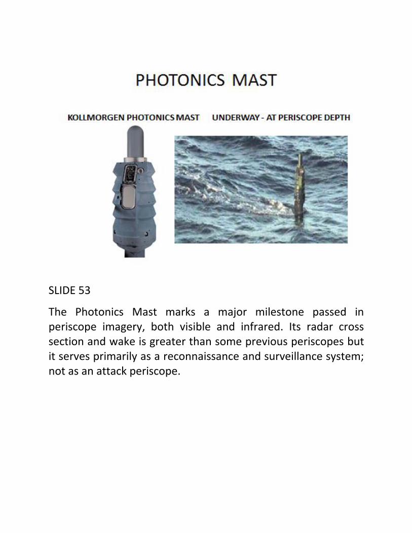
SLIDE 53
The Photonics Mast marks a major milestone passed in periscope imagery, both visible and infrared. Its radar cross section and wake is greater than some previous periscopes but it serves primarily as a reconnaissance and surveillance system; not as an attack periscope.

SLIDE 54
Project Azorian
In 1974, as some of you may recall, a special ship built by Hughes called the Glomar Explorer and a special barge named the HMB-1 carrying a giant claw built by Lockheed and nicknamed “Clementine”, recovered part of a Soviet submarine from a depth 16,000 feet. Hughes had a cover story. Officially, Hughes was out to mine manganese nodules. The story hung together until key elements of the Hughes contract with the CIA were leaked to the press and details were published in the LA Times.

SLIDE 55
Locating the K-129 and keeping the knowledge of its disposition secret during the cold war was a miracle. Retrieving it under the Soviet Navy’s nose was a masterpiece in covert operations. Here is a picture of the K-129 on patrol. Listed on the right side of this slide at the bottom is the nuclear treasure that she carried.
Itek’s role in the Azorian Project was to develop the camera and illumination system for the CIA.
I became involved in the Project as a result of completing sea trials with Itek’s version of the Type 18 periscope prototype in 1970. My task was to design the camera and lighting system for deep ocean applications. No reason given. This project at Itek was hush-hush so I guessed that it was for a covert operation and some unnamed intelligence agency. The stated purpose however, was to find manganese nodules on the ocean floor.
So how did Itek get away with this “stated purpose” and how was this cover story implemented for the rest of the Itek employees and the public at large?
Frank Lindsay, then Chairman of Itek, asked me to brief Sir Victor Rothschild, a former MI5 Agent, friend of OSS and worldwide head of research at Royal Dutch Shell (the Hague) on the technology that Itek was developing for the business of recovering manganese nodules. Sir Victor was impressed and asked some pointed questions about the chances of success. He seemed interested both in the cameras and lighting scheme…. I assumed for deep ocean, oil drilling operations….as well as the metallurgy. This latter interest was because Royal Dutch Shell had just purchased Billiton. Billiton’s roots trace back to 1860 and a tin mine on a little known island in Indonesia, Billiton (Belitung) island, which was ceded by the British to the Dutch in 1924. Billiton was a leader in the metals and mining sector and a major producer of manganese ores and alloys.
Most of the intricate details of my involvement in Project Azorian are described in Craig Reed’s book “Red November”,

released last year. Craig includes an anecdote which I will share with you tonight.
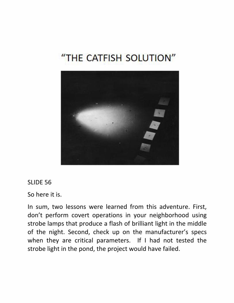
The strobe lights that I selected for the job were supposed to illuminate a cone angle of 90 degrees, according to the manufacturer’s specs. Since this angle was critical to the success of the project, I decided to get proof using a primitive but effective method. The project was highly classified and the test had to be conducted in total secrecy. In our backyard in Sudbury, Massachusetts, was a pond… a cranberry bog….about 3 feet deep in the center. I placed the strobe light underwater near the shore, waded out into the middle of the pond and installed white boards facing upwards at a 45 degrees angle. There was a tree overhanging the pond so I climbed out on a large limb holding my camera directly over the reflective boards. I asked my 15 year old son to trigger the strobe, and we captured the result on film. (Later, he developed “pond fever” and was not happy about the test since the fever interfered with his basketball practice). I developed the film and noticed that not only was the illuminated angle only 60 degrees, much smaller than the stated 90 degrees in the manufacturer’s specs but also, I realized that the strobe light had “caught” some catfish in the frame. When I showed the image to Itek’s customer, John Parangosky, known under the code name Mr. P., he promptly labeled this feat as “the catfish solution.” Unfortunately, Craig’s book did not have sufficient space for the famous image.
SLIDE 56
So here it is.
In sum, two lessons were learned from this adventure. First, don’t perform covert operations in your neighborhood using strobe lamps that produce a flash of brilliant light in the middle of the night. Second, check up on the manufacturer’s specs when they are critical parameters. If I had not tested the strobe light in the pond, the project would have failed.

If you are interested in further details, the following is a list of books that I can highly recommend for recreational as well as technical reading.
SLIDE 57

SLIDE 58 – EARLY CONSULTANTS
In March 1981, after 20 years in industry, HRA opened its doors for business. Launching a sole proprietorship was very much like the Indian warrior who gets too old to hunt. He has a lot of experience to share and a large percentage of that experience is gleaned from reading buffalo spore….or at least, recognizing buffalo spore when present.

SLIDE 59
Given that most of my activities between 1961 and 1981 involved the Intelligence Community (IC), HRA’s first contracts occurred as a result of familiarity with the customer’s requirements; many of the needs were presented in “white papers” and classified reports. Intec, Honeywell and Systems Research Lab were HRA’s first customers. California Microwave, Probe Systems and Hughes/Perkin-Elmer soon followed suit. Some of these organizations were involved with the IC.
SLIDE 60
HRA continued providing support to the Director of Naval Intelligence through OP-009U. This support involved analysis and technical guidance relating to submarine periscope imagery. Work was performed at SSEPs and with organizations such as SubDevGp-2. Deep submergence vehicle operations were also addressed. Travels to exotic destinations such as Vallejo, CA, were part of the tasking.

SLIDE 61
Six months after HRA became a sole proprietorship, I received a call from the U.S. Army Intelligence & Security Command to join them as a Consultant (GS-15E) and help guide the Command’s Electro-Optic projects. My branch chief was Al Murdock who had retired from a career in Army Intelligence and was in the forefront of assessing the Soviet and East German military technical capabilities. My first visit on behalf of the Command was to Field Station Berlin. There I would be briefed on the latest findings and fly over the East German Army tank training ranges in the Larkspur (Pilatus) aircraft. A 1947 treaty allowed all four sides in the cold war (British, French, American and

Soviets) to conduct surveillance missions under certain protocols without being attacked.
SLIDE 62
The result of not following these protocols is illustrated in this slide. Major Arthur D. Nicholson, Jr., USA, who was assigned to the U.S. Military Liaison Mission, was perhaps the last casualty of the cold war.

SLIDE 63
The 1980s saw turbulence in many quarters. In the mid-80s during the Reagan Administration, I was tasked with supporting Southern Command located at Quarry Heights in the Panama Canal Zone. General Gorman, the Command’s CINC, requested that special surveillance assets be placed on Tiger Island off the coast of Honduras, to provide early warning of Sandinistas (Frente Sandinista de Liberación Nacional) who were bringing weapons into that part of Central America by boat. Dr. Rudy Buser, Director of the Night Vision Lab, Al Murdock and I spent hours in Huey helicopters and C-130 transport aircraft hopping

around the area analyzing the terrain and weather patterns. We learned early on that weather is the main enemy of optical surveillance.
SLIDE 64
A year later, the NSA requested assistance with one of its groups stationed in Sinop, Turkey, on the Black Sea. I flew into Istanbul and climbed into an Army transport (twin prop) for a ride to the ancient town of Sinop. During my visit, I surveyed the area for optical collection sites to support a study of long path length “ducting”, a phenomenon that is associated with electromagnetic radiation propagating near sea level under

unique climatic conditions. The site was ideal for observing Soviet military activities including rocket launches and overhead satellite operations. The site hosted multiple agencies and a large variety of sophisticated sensors.
SLIDE 65
Another high priority U.S. Army intelligence target was North Korea. My 13 months as the 2nd Engineer Group aviation officer had convinced me in the late 50s that the war on the Korean Peninsula at that time was still going on…and still is! With a cease fire and no armistice, the North is constantly baiting the South and attempting to subvert South Korea’s
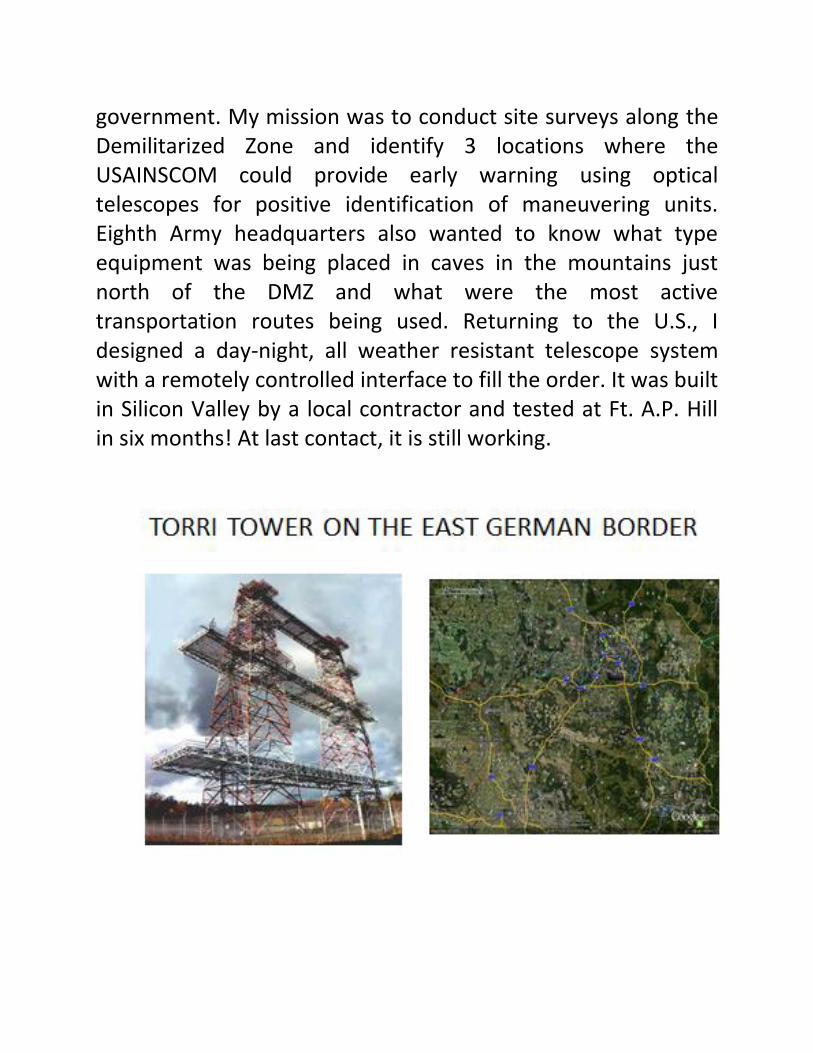
government. My mission was to conduct site surveys along the Demilitarized Zone and identify 3 locations where the USAINSCOM could provide early warning using optical telescopes for positive identification of maneuvering units. Eighth Army headquarters also wanted to know what type equipment was being placed in caves in the mountains just north of the DMZ and what were the most active transportation routes being used. Returning to the U.S., I designed a day-night, all weather resistant telescope system with a remotely controlled interface to fill the order. It was built in Silicon Valley by a local contractor and tested at Ft. A.P. Hill in six months! At last contact, it is still working.

SLIDE 66
In 1986, the first order of business was to confirm the presence of laser range finders on weapon platforms operating in the Letzlinger-Heide training area east of Berlin but near the western border of East Germany. At that time the Army had a field site located in the Elm Forest near Wobeck (which was at that time in West Germany) on the border of East Germany just outside the village of Schoningen. The site supported both signals and communications intercept organizations and had a tower known as a Torri tower with a large array of antenna for collecting foreign signals. It was an ideal listening station and with its 265 foot height, standing on a 775 foot hill, the total of 1,040 feet altitude MSL meant that an optical system would have easy line-of-site to tanks, artillery and helicopters operating at 370 feet MSL up to 70 miles away.

SLIDE 67
One of our targets was the Mi-8MT “HIP” helicopter. The Night Vision Lab at Ft. Belvoir, VA, under the direction of Dr. Rudolf Buser and the supervision of Al Murdock, designed and built an optical detection device. Eliminating the possibility of false alarms was the driving requirement. After six months of intensive research on the L-H training area including analysis of the East German field exercises and the incidence of potential targets versus weather patterns, I installed the device on the highest rail of the tower and pointed it along an azimuth of 62.5 degrees grid north. Within a week we had our first ever intercept. The rest is history.

SLIDE 68
In 1987 and 1988, the Night Vision and Electro-Optical Laboratory built a 60-inch telescope capable of staring at 10 degrees of horizon. Before it could be deployed “the wall came down.” Last heard it was being transferred from Tullahoma, TN, to White Sands, NM, where it should reside in a first class, historical museum of optical equipment established by SPIE pioneers, Jed Durrenberger and Austin Vic. RIP LITES!

SLIDE 69
One final comment: Owing to the success of USAINSCOM’s collection program……almost 100 fielded systems in 5 years……the Night Vision Electro-Optical Laboratory established a TECRAS (Technical Reconnaissance and Surveillance) project office to further the reduction to practice of scientific advances aiding development of Army weapon programs. One of its major achievements was how to use laser technology on the modern battlefield. This was just one of Dr. Rudolph G. Buser’s legacies.
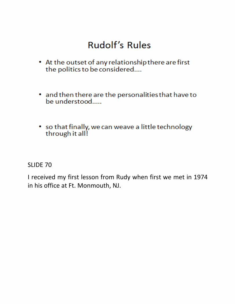
SLIDE 70
I received my first lesson from Rudy when first we met in 1974 in his office at Ft. Monmouth, NJ.

SLIDE 71
With the support of SPIE and the Night Vision Lab, HRA helped to “stand up” the Defense Airborne Reconnaissance Office (DARO). NVL and HRA were among the first organizations to identify and begin to implement the Predator project sensor requirements at General Atomics in San Diego. We met RAdm. Tom Cassidy, pioneer in UAVs, in his facility north of San Diego. He gave us a tour of the factory and demonstrated a live operation underway. Dr. Buser took note of the Predator’s unique design and inherent stability as an airborne platform and together we began to talk about a new sensor program at NVL. Dr. Buser went on to establish a UAV project office at NVL.
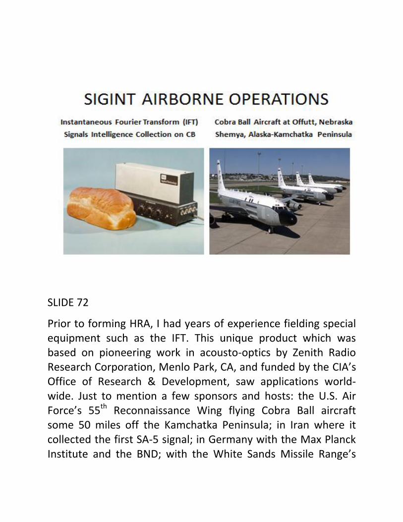
SLIDE 72
Prior to forming HRA, I had years of experience fielding special equipment such as the IFT. This unique product which was based on pioneering work in acousto-optics by Zenith Radio Research Corporation, Menlo Park, CA, and funded by the CIA’s Office of Research & Development, saw applications world-wide. Just to mention a few sponsors and hosts: the U.S. Air Force’s 55th Reconnaissance Wing flying Cobra Ball aircraft some 50 miles off the Kamchatka Peninsula; in Iran where it collected the first SA-5 signal; in Germany with the Max Planck Institute and the BND; with the White Sands Missile Range’s

Vulnerability Assessment Lab: through George Roberts, a major sponsor; at GCHQ in England; with the National Security Agency; and with SubDevGp-2, supported by Prof. Steve Jauregui and Ray Vincent of the Naval Postgraduate School. The principal of operation is simple. Radar and communications signals feed an antenna. The antenna is coupled to an acousto-optical device (a Bragg cel), often a crystal of Lithium Niobate). Excitation set up by a transducer creates a grating effect in the device. If one passes a gas laser beam through the cell, the beam is diffracted across a focal plane onto a linear array of photo-detectors. It turns out that the angle of deflection of the laser beam is directly proportional to the incoming frequency of the signal. Thus for a wide band of the EM spectrum, one can analyze frequency hoppers and spread spectrum in real-time. As one pundit said, “some people see some of the signals all of the time, others see all of the signals part of the time, but with the IFT, one sees all of the signals all of the time”. I organized many conferences and edited several proceedings on this subject in the event you are interested in learning more about this subject.

SLIDE 73
Congressman Norman Mineta, San Jose, CA, and Joe Russell of California Microwave, Woodland Hills, CA, had a vision of taking the best of lessons learned from SAC’s 55th Reconnaissance operations, combining that vision with the dedication of veterans of the SR-71, U-2, and RC-135 platforms and using commercial off-the-shelf technology, create a new and more cost-effective, intelligence gathering aircraft. This capability was later acquired by Northrop Grumman. I was fortunate to work alongside these cold war warriors and provide guidance
on the selection, design and integration of a number of optical sensors.
SLIDE 74
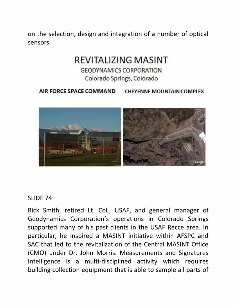
Rick Smith, retired Lt. Col., USAF, and general manager of Geodynamics Corporation’s operations in Colorado Springs supported many of his past clients in the USAF Recce area. In particular, he inspired a MASINT initiative within AFSPC and SAC that led to the revitalization of the Central MASINT Office (CMO) under Dr. John Morris. Measurements and Signatures Intelligence is a multi-disciplined activity which requires building collection equipment that is able to sample all parts of
the electro-magnetic spectrum and glean intelligence through the detection of unique signals emanating from a suspicious source, e.g., mine tailings, residual radiation, and vibrations resulting from sound waves coupling into the alluvial soil.
My role was to organize collection “assets” throughout the Intelligence Community (IC), convene tri-service technical discussions and workshops in Colorado Springs, and ferret out the latest advances in each sub-discipline. This activity required travel to Los Alamos National Labs, Sandia Labs, Army Research Labs, Lawrence Livermore Labs and some 30 other locations involved in covert collection projects. Three major agencies contributed their share: NSA, DIA and CIA.

SLIDE 75
Note the four primary intelligence disciplines illustrated on the left side of this slide. Note also the broad band of useful MASINT products on the right.

SLIDE 76
I arrived on H Street in beautiful downtown Washington, DC, in 1984 a week after LG Jim Abrahamson, USAF and Dr. Jim Ionson “stood up” the Strategic Defense Initiative (or Star Wars). When asked what basic research projects needed to be funded for the benefit of the SDIO, I responded that we should fund a University Initiative, a Consortium, in Optical Computing. Ours was the first of many consortia implemented by the SDIO. Six months and $3M later, some 29 universities and research institutes were at work on a number of different approaches to bringing optical computing closer to reality.
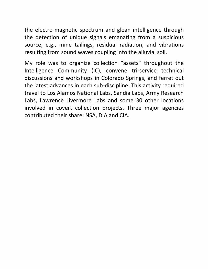
SLIDE 77
This first meeting with Jim was the beginning of a close working relationship. My tasks included appointments at two universities and one research institute plus appearances on PBS specials to explain and defend the Innovative Science & Technology office’s pursuit of R&D.

SLIDE 78
As time passed, SDIO became the Ballistic Missile Defense Organization and was headed up by an Army colleague, LG Malcolm O’Neill. In 2002, the BMDO became the Missile Defense Agency: it is currently commanded by LG Pat O’Reilly, US Army.
The SHOTS project shown in this slide was managed by Delmar Haddock of the Navy’s Space and Naval Warfare Systems Command (acronym is SPAWAR) headquartered here on Pt. Loma in San Diego. The contract to build this unique optical system was awarded to SORL of Chelmsford, MA. My role was to coordinate the manufacturing processes with the Navy’s

demanding objectives and tight schedule. I was ably assisted by Alan Decew of MIT Lincoln Labs. We supported the chief engineer, Jim Sterritt, in achieving all the stated objectives. SORL delivered two systems to the Navy over two years ago.
The SHOTS system has performed admirably at sea and accomplished its mission of recording high velocity intercepts (and explosions). These explosions represent “good news” since they occur when an irresistible “good guys” interceptor missile impacts and immovable “bad guys” reentry missile in outer space. It makes quite an impression on the observer, too.
SLIDE 79 is a “shot” of SHOTS at sea with the setting sun as a backdrop.

SLIDE 80
Turning to an entirely different subject but one that is very relevant when it comes to discussing this week’s international symposium.
It wasn’t always this calm in August. Take August 1982 when the Pentagon, then under the command of Caspar “The Knife” Weinberger, tasked his minions with bullying the SPIE and threatening to throw its members in jail.

SLIDE 81
When the smoke cleared and SPIE lost over 100 technical papers out of 700 (14%), the DOD admitted “it went badly”…a quote from Dr. Stephen Bryen, Deputy Assistant Secretary for International Economic, Trade and Security Policy. He later commended the Society for its excellent and constructive cooperation. See copy of letter from Dr. Bryen to SPIE President Richard Wollensak dated 15 September 1982.
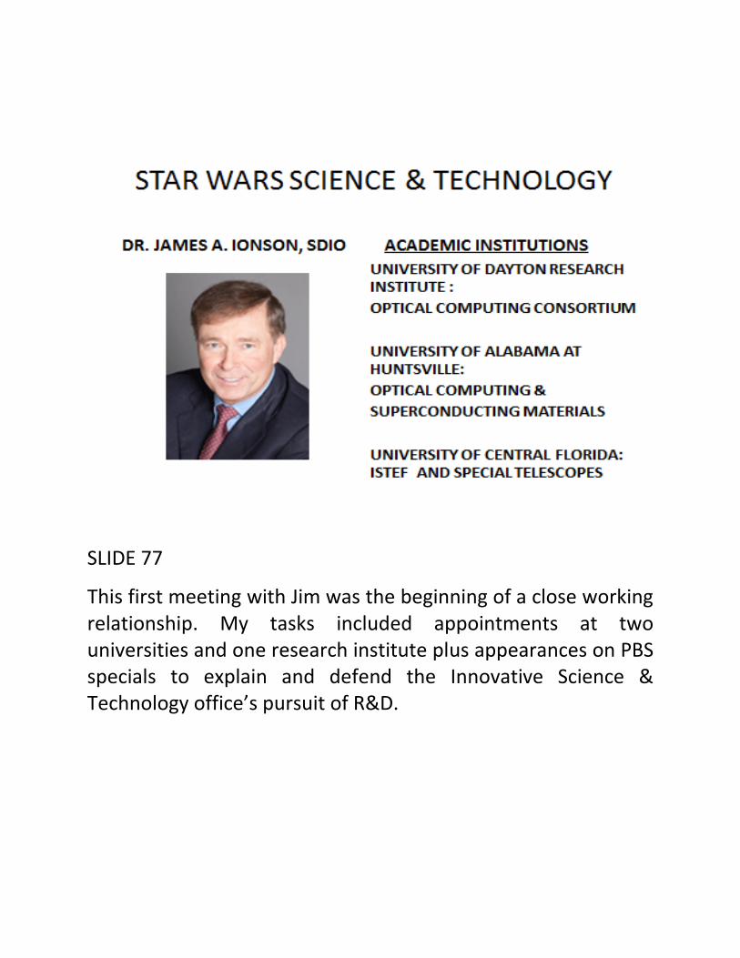
SLIDE 82
SPIE’s response to the issue was direct and to the point. Note the eight “bullets” that outline SPIE’s position and lists our constructive suggestions. I was privileged to participate in Sub-Panel A activities, represent the SPIE on matters involving potential problems with authors and papers from the government laboratories and advise the SPIE staff on matters of concern in upcoming symposia.
In the subsequent months an accommodation was made with the Department of Defense and I went to work with Frank Sobiesczyk and Dr. Edith Martin, Deputy Under-Secretary of

Defense for Research and Advanced Technology for the U.S. Department of Defense, re-writing portions of DOD Directive 5230; primarily eliminating loopholes and flaws in the approval cycle for technical papers being presented at both national and international conferences.
SLIDE 83
These are the main products of the SPIE and DOD Tech Transfer cooperative efforts.
SLIDE 84
Finally, we take a brief look at the optical technology that supports our national missile test ranges. Working with the Optical Systems Group, a member organization of the RCC, I learned how to address the ranges’ current needs and save money at the same. Note that part of the OSG’s charter is to save money through the upgrading or transfer of existing telescopes and optical accessories. An interesting fact: SPIE essentially derived from the OSG and has provided a forum for OSG technical subjects since 1956.

SLIDE 85
The nation’s operational ranges all have the same objective (no pun intended). The telescope in use at the time of launch and “fly-out” must maintain focus. There is nothing sadder than a fuzzy image when the mission goes critical.
Five major organizations are illustrated in this slide along with the two important issues facing range management on a daily basis.

SLIDE 86
My first task involved refurbishing the Distant Object Attitude Measurement System or DOAMS. Since I was one of the authors of the original, winning proposal, this was a great opportunity. Thanks to Scott Smith, Chuck Malone and George Economou of Contraves, the ten pairs of telescopes were delivered to WSMR with the advantage of having completely interchangeable components.
Note the embedded video showing a typical Shuttle launch.

SLIDE 87
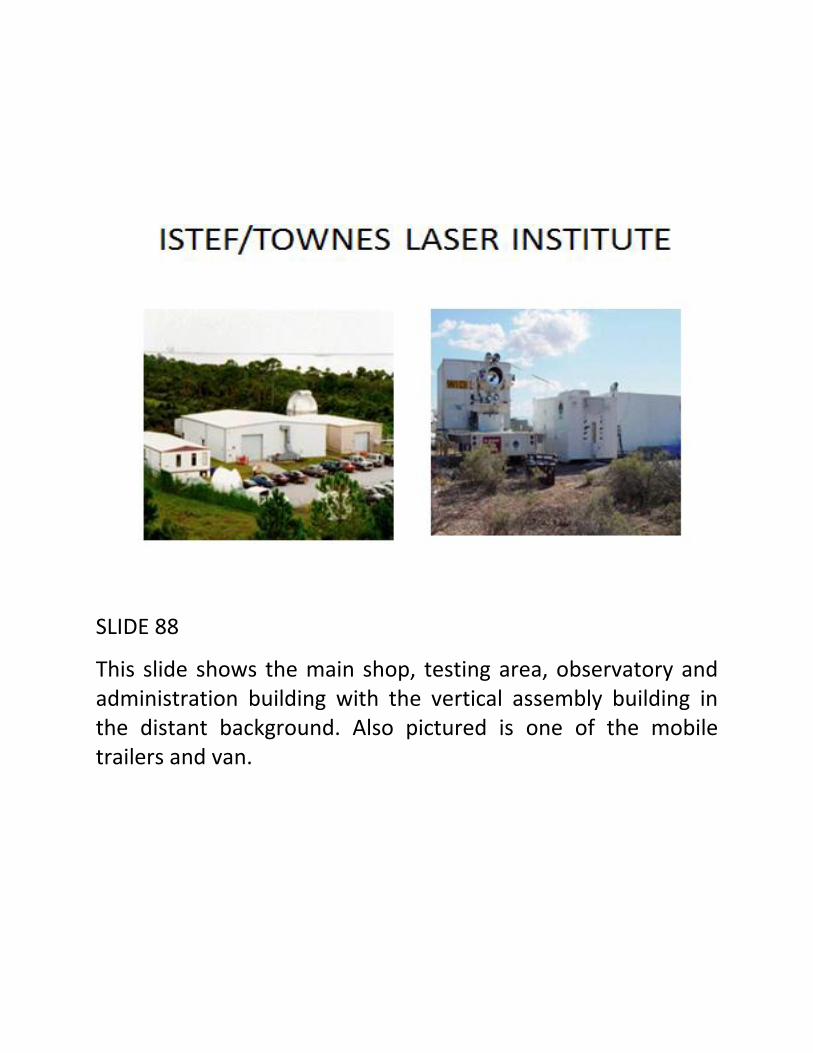
Until last year, the Missile Defense Agency supported a science and technology initiative near the launch pads at Cape Kennedy. See map. The ISTEF (Innovative Science & Technology Experimentation Facility) established by Dr. Jim Ionson, has certain unique capabilities which include mobile telescope and laser range gated imaging. I supported the ISTEF for several years, building new telescopes and refurbishing old telescopes. See picture on right of two refurbished telescopes. The latest plan is to rename the ISTEF the “Townes Laser Institute” and maintain its advanced laser and IR technology expertise.
SLIDE 88
This slide shows the main shop, testing area, observatory and administration building with the vertical assembly building in the distant background. Also pictured is one of the mobile trailers and van.

SLIDE 89
For White Sands, I refurbished a DOAMS telescope and with the help of a talented optician and lens designer, Randy Dewees of China Lake, converted one of the pair of telescopes to image in the infrared. The mechanical work was performed by a Navy public works shop here in San Diego. I was lucky to have the expertise and experience of Hal Malinski, also a teacher of amateur telescope making in the local community.
SLIDE 90
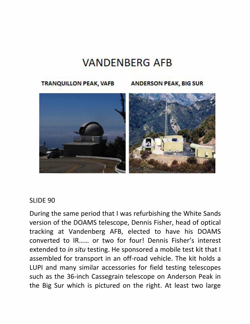
During the same period that I was refurbishing the White Sands version of the DOAMS telescope, Dennis Fisher, head of optical tracking at Vandenberg AFB, elected to have his DOAMS converted to IR…… or two for four! Dennis Fisher’s interest extended to in situ testing. He sponsored a mobile test kit that I assembled for transport in an off-road vehicle. The kit holds a LUPI and many similar accessories for field testing telescopes such as the 36-inch Cassegrain telescope on Anderson Peak in the Big Sur which is pictured on the right. At least two large

telescopes were used in the last several years to record launch events associated with Vandenberg. A 24-inch Newtonian on Tranquillon Peak has been replaced recently with the modified DOAMS to cover launches at a relatively short range. More recently, Vandenberg with the encouragement of Dennis Fisher, has sponsored an impressive array of larger telescopes installed on a Photo-Sonics mobile mount for assignment to any part of the world.
SLIDE 91
The Range Tracking Telescope community has a legacy of successful innovations. SPIE pioneer, Jack Kiel, and son, Philip, of Photo-Sonics, Inc., are among the legends. This slide depicts the ideal management arrangement for the ranges in order to
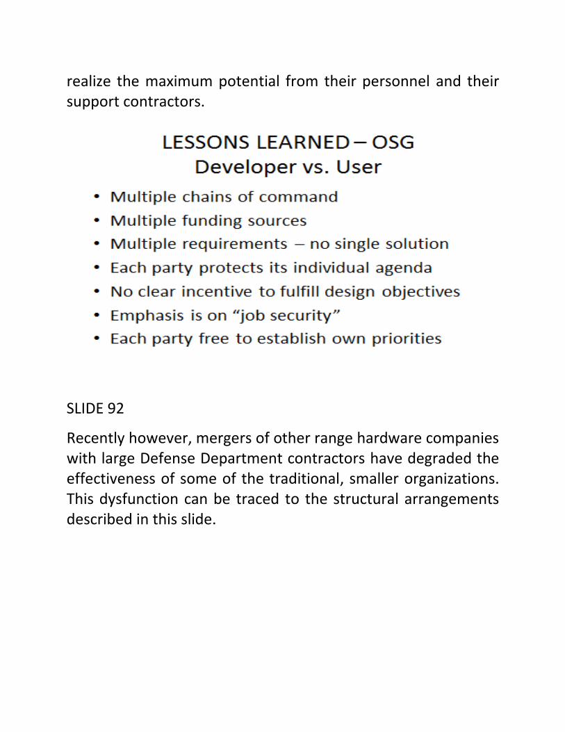
realize the maximum potential from their personnel and their support contractors.
SLIDE 92
Recently however, mergers of other range hardware companies with large Defense Department contractors have degraded the effectiveness of some of the traditional, smaller organizations. This dysfunction can be traced to the structural arrangements described in this slide.

SLIDE 93
Throughout my presentation, lessons learned in the field….by trial or by error…have been the basis for sharing information.
I leave you with this personal summary.
IN REFLECTION, I MUST PARAPHRASE ISAAC ASIMOV, WHO SAID TO ME…..WITH A TWINKLE IN HIS EYE…THE LAST TIME WE MET TOGETHER IN HIS APARTMENT NEAR CENTRAL PARK: (QUOTE) “IF I HAD ONLY KNOWN THEN WHAT I KNOW NOW, I COULD HAVE WRITTEN EVER SO MUCH BETTER SCIENCE FICTION.”
LIKEWISE:
“IF I HAD ONLY KNOWN 50 YEARS AGO WHAT I HAVE LEARNED ABOUT OPTICS IN THE INTERVENING YEARS, I WOULD HAVE DONE AN EVER SO MUCH BETTER JOB.”
SLIDE 94
“Always guard against the flanking attack!”
ACKNOWLEDGMENTS
The author has been most fortunate to have had many mentors and role models during his career in optics; many of them have been identified in this presentation. In addition to those mentioned, there is my former high school physics teacher, Michael Baranelli, who encouraged me to pursue a career in science and Mr. C. C. Pinckney, a retired engineer who invited me to look through his telescope and get my first close up view of Saturn.

Without the support and encouragement of my wife Elizabeth, and our son, Brant, none of these adventures would have been possible. Day and night, fair weather or storm, their patience and understanding have always been there.
Finally, the episodes described in this presentation came as opportunities and challenges……a toss of the dice…….and required help from a variety of sources. Most of these sources are identified in the slides, many of whom have passed on. The author appreciates the chance to buttress their legacy so that others may benefit from their shared experiences.