introduction: getting started with metrowerks codewarrior
TRANSCRIPT

88
INTRODUCTION: Getting Started With Metrowerks CodeWarrior Tutorial: The aim of this tutorial is to help the first time user of Metrowerks CodeWarrior to be able to create a project. In addition a clear explanation of every option that is used in the process is provided. Also, a final tree structure of the contents of the project folder is provided. CodeWarrior IDE contains of all tools mentioned below:
• Project Manager: Handles top-level file items by major group, such as files and targets; tracks state information (such as file modification dates); determines build order and inclusion of specific files in each build; coordinates with plug-ins to provide services like version-control.
• Text Editor: Enables the creation and manipulation of source code and other textual files.
• Search Engine: Finds a specific text string replaces found text with substitute text; allows use of regular expressions; provides file-comparison and differencing functionality.
• Source Browser: Maintains a symbolics database for the program; examples of symbols include names and values of variables and functions; uses the symbolics database to assist code navigation; links every symbol to other locations in the code related to that symbol; processes both object-oriented and procedural languages.
• Build System: Uses the compiler to generate relocatable object code from source code and uses the linker to generate a final executable image from object code
The CodeWarrior Integrated Development Environment (IDE) uses projects and build targets to organize the files and settings for creating a program. A project is a file that contains one or more build targets. Each build target in a project is a collection of files that the IDE uses to create (build) an output file. A build target can contain these elements:
• Source code files • Libraries • Settings • Other projects
Build targets in a project can share the same files, but each build target has its own settings.

89
LAUNCHING OF IDE: CodeWarrior IDE can be invoked either using the command line option or through the short cut that is placed after installation from the start menu. Command line option: Figure1 From the Windows task bar menu, click on the start and select Run to open command window as shown in the Figure2.

90
Figure 2 Either type the path or use the Browse option to select the IDE.exe and then click OK. Shortcut option: Figure 3 Follow the path start All Programs Metrowerks CodeWarrior CW12 V3 and then click on CodeWarrior IDE.

91
Figure 4 An IDE window pops as shown above. Menu bar Tool bar Figure 5 We can observe that a toolbar is attached to the menu at the top of the IDE screen. Toolbar contains the buttons that are shortcuts to frequently used menu items.

92
CREATING A NEW PROJECT IN C: Step1: Figure 6 Using the Menu bar: Figure 7 Using the Tool bar:

93
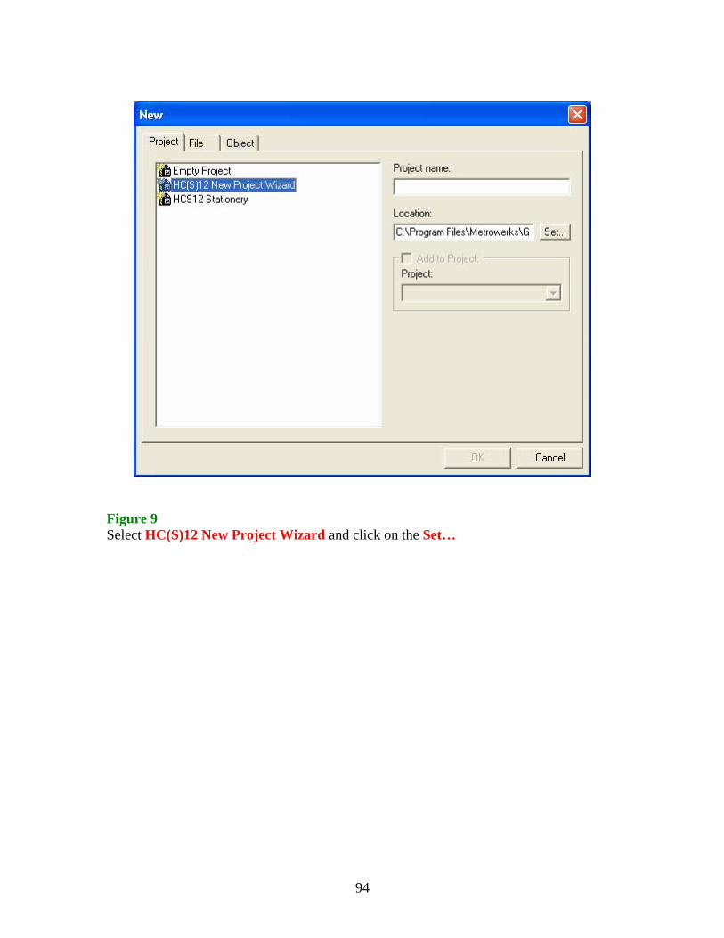
Figure 8 A Project creation dialog box pops up CodeWarrior project wizard presents three main options:
Empty Project Creates the very minimum of files required, essentially just creating the project file. User has to write every thing from scratch.
HC(S)12 New This option allows the user to choose the appropriate Project Wizard device on which the project to be built on, and is most
commonly used wizard. HCS12 Stationery Provides as a quick start to use one of the demo boards,
with some skeleton code. Also provides the HC12 board support of the previous CodeWarrior and is not used for HCS12 devices or board.
94
Figure 9 Select HC(S)12 New Project Wizard and click on the Set…

95
Figure 10 A window pops up with Create New Project… title. Choose the location, give a name in the File name box and click on the Save

96
Step2: Figure 11 A window pops up with title New Project Wizard – Page 1. Click on the Next >. This option allows you to select the derivative i.e., the processor upon which you want to build the project. In my case the I-PAC HSC12 board from EMAC inc. has MC9S12DG256BCPV micro-controller built on it.

97
Step3: Figure 12 A window pops up with title New Project Wizard – Page 2. Click on Next >. This option allows you to select the language in which you want to code your program. In this case I selected C as my language. Note: IDE allows you to select multiple languages such as Assembly & C, Assembly & C++.
98
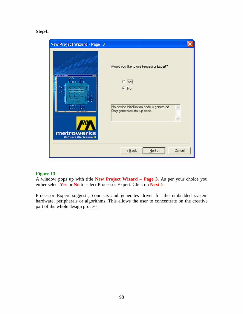
Step4: Figure 13 A window pops up with title New Project Wizard – Page 3. As per your choice you either select Yes or No to select Processor Expert. Click on Next >. Processor Expert suggests, connects and generates driver for the embedded system hardware, peripherals or algorithms. This allows the user to concentrate on the creative part of the whole design process.

99
Step5: Figure 14 A window pops up with title New Project Wizard – Page 4. As per your choice you either select Yes or No to select PC-lint. Click on Next >. PC-lint is a software tool from Gimpel Software inc. It is used to thoroughly check your C/C++ source code for bugs, glitches, inconsistencies, non-portable constructs, and much more. If you possess this software tool then you need to use this option.

100
Step6: Figure 15 A window pops up with title New Project Wizard – Page 5. As this processor doesn’t support Floating point format select No. Click on Next >.

101
Step7: Figure 16 A window pops up with title New Project Wizard – Page 6. As per your need of usage of memory select one out of three models Small, Banked and Large. Click on Next >. Metrowerks CodeWarrior Compiler supports three different memory models.
(i) SMALL memory model corresponds to flat memory map of 64K byte of code addressing. By default, all functions are of type ‘near’ in this model.
(ii) BANKED memory model supports paged addressing of code. By default, all user defined functions are of type ‘far’ in this model.
(iii) LARGE memory model supports both paged addressing of code and data. All functions and data pointers are of type ‘far’ in this model. Due to the increase in overhead of necessary runtime routines, this memory model is not widely used.
Note: near and far are two non-ANSI keywords introduced by CodeWarrior compiler to efficiently handle the paged memory.

102
Step8: Figure 17 A window pops up with title New Project Wizard – Page 7. Depending upon the interface that is available, select the corresponding option and then click Finish. This window allows the user to select the type of connection/target upon which the project to be build. The IDE even allows the user to create project for multiple connections/targets at a time. Figure 18 Above window pops up showing that the project creation is in process.

103
Once the project is created all the items are organized using three different pages Files, Link Order and Targets. All the three pages are shown following the general complete view of IDE after the creation of project. Figure 19 Project creation is now complete!

104
Figure 20 Link Order page shows the order of the files in the project in which they are linked.
105
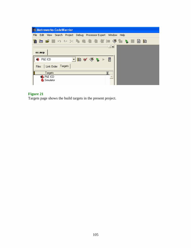
Figure 21 Targets page shows the build targets in the present project.
106
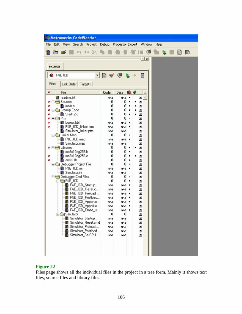
Figure 22 Files page shows all the individual files in the project in a tree form. Mainly it shows text files, source files and library files.

107
General overview of files that are created in the project: • readme.txt
- Initially contains a brief overview of the project structure, details of on-line help and how to contact Metrowerks.
• Sources - Contains the users source code, sample main.c provided by wizard with project creation.
• Startup Code - Start12.c – C/C++ startup code which initializes the C library and invokes the user code (main function).
• Prm - burner.bbl – details of how to generate the required S-Record for the debugger. - *.prm – details of how to link code/data segments. - *.map – generated by linker.
• Libs - Required library files (ANSI library) - Device header and device file
• Debugger Project File - Contains an *.ini file for the debugger – essentially a project file for the debugger.
• Debugger Cmd Files - Contains sub-folders for each target connection method, along with command files.
The new project wizard creates enough code to actually load into a board and run/debug. The main program (main.c) being: #include <hidef.h> /* common defines and macros */ #include <mc9s12dg256.h> /* derivative information */ #pragma LINK_INFO DERIVATIVE "mc9s12dg256b" void main (void) { /* put your own code here */ EnableInterrupts; for (;;) {} /* wait forever */ } Note: All the application code must be written in this main() function. The main function shown above is the default function with minimal code created by IDE.

108
The parameter linker file being: NAMES END SEGMENTS RAM = READ_WRITE 0x1000 TO 0x3FFF; /* unbanked FLASH ROM */ ROM_4000 = READ_ONLY 0x4000 TO 0x7FFF; ROM_C000 = READ_ONLY 0xC000 TO 0xFEFF; /* banked FLASH ROM */ PAGE_30 = READ_ONLY 0x308000 TO 0x30BFFF; PAGE_31 = READ_ONLY 0x318000 TO 0x31BFFF; PAGE_32 = READ_ONLY 0x328000 TO 0x32BFFF; PAGE_33 = READ_ONLY 0x338000 TO 0x33BFFF; PAGE_34 = READ_ONLY 0x348000 TO 0x34BFFF; PAGE_35 = READ_ONLY 0x358000 TO 0x35BFFF; PAGE_36 = READ_ONLY 0x368000 TO 0x36BFFF; PAGE_37 = READ_ONLY 0x378000 TO 0x37BFFF; PAGE_38 = READ_ONLY 0x388000 TO 0x38BFFF; PAGE_39 = READ_ONLY 0x398000 TO 0x39BFFF; PAGE_3A = READ_ONLY 0x3A8000 TO 0x3ABFFF; PAGE_3B = READ_ONLY 0x3B8000 TO 0x3BBFFF; PAGE_3C = READ_ONLY 0x3C8000 TO 0x3CBFFF; PAGE_3D = READ_ONLY 0x3D8000 TO 0x3DBFFF; /* PAGE_3E = READ_ONLY 0x3E8000 TO 0x3EBFFF; not used: equivalent to ROM_4000 */ /* PAGE_3F = READ_ONLY 0x3F8000 TO 0x3FBFFF; not used: equivalent to ROM_C000 */ END PLACEMENT _PRESTART, STARTUP, ROM_VAR, STRINGS, VIRTUAL_TABLE_SEGMENT, DEFAULT_ROM, NON_BANKED, COPY INTO ROM_C000, ROM_4000; OTHER_ROM INTO PAGE_30, PAGE_31, PAGE_32, PAGE_33,
PAGE_34, PAGE_35,PAGE_36,PAGE_37, PAGE_38,PAGE_39,PAGE_3A,PAGE_3B, PAGE_3C,PAGE_3D;
DEFAULT_RAM INTO RAM; END STACKSIZE 0x100 VECTOR 0 _Startup /* reset vector: this is the default entry point for a C/C++ application. */ //VECTOR 0 Entry /* reset vector: this is the default entry point for a Assembly application. */ //INIT Entry /* for assembly applications: that this is as well the initialisation entry point */ Note: The above file shows the memory segmentation, the placements of routines in memory segments and the placement of interrupt routines in the vector table. Few examples are mentioned below that illustrates programming in C, Assembly and both C & Assembly.

109
PROGRAMMING IN C: This is a small program in which sum of two variables is stored in third variable. Also this is the first program that is compiled to generate executable file and downloaded on to the board and run. The output is observed on PC by looking at the memory location of the result through debugger. main.c (Source file): #include <hidef.h> /* common defines and macros */ #include <mc9s12dg256.h> /* derivative information */ #pragma LINK_INFO DERIVATIVE "mc9s12dg256b" void main (void) {
/* put your own code here */ unsigned int x = 3, y = 4, z; EnableInterrupts; z = x + y; for (;;) {} /* wait forever */
} Notes: hidef.h is the header file in which macros and few definitions related to processor are done. For example the EnableInterrupts function used in the main function is defined in this file. mc9s12dg256.h is the header file in which device (register) definitions are done.
110
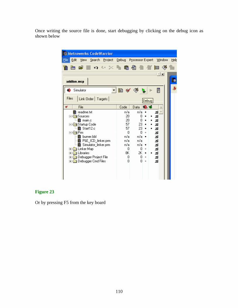
Once writing the source file is done, start debugging by clicking on the debug icon as shown below Figure 23 Or by pressing F5 from the key board

111
Or Select Project from the menu bar of IDE and then select Debug from the drop-down box to start debugging the project: Figure 24

112
The following True-Time Simulator and Real-Time Debugger window pops-up: Source Procedure Data1 Assembly Data2 Register Memory Command Figure 25

113
OUTPUT IN THE CASE OF SIMULATOR AS BUILD TARGET: The following data window in the simulator shows the values of variables before and after the simulation. Figure 26 Before Simulation Figure 27 After simulation

114
OUTPUT IN CASE OF P&E ICD AS THE BUILD TARGET: The following True-Time Simulator and Real-Time Debugger window with a another small window saying mass erase of flash memory message pops-up as and when debug option is opted in either way shown on pages 23 and 24: Figure 28 Click Ok

115
In the following figure, the memory locations of the variables used in the program are highlighted in the Memory window. The locations show the values before running the program. Figure 29

116
In the following window the locations of the variables are changed and this indicated by change in the color from black to red. Also we can watch the output to be the same as the output observed in the case of Simulator. Also we can observe that data is stored inside in the ASCII format. Figure 30

117
PROGRAMMING IN ASSEMBLY: There are two kinds of projects that can be created in assembly language.
(i) Relocatable Assembly: In this case the code is placed in the memory according at the time of linking. Code Sections are placed in the Default Rom and Data Sections are placed in the Default Ram.
(ii) Absolute Assembly: In this case the starting address at which the code is placed is determined at assembly time.
In the above process of project creation Step3 to Step7 are replaced by following two steps. CREATING A PROJECT IN ASSEMBLY - RELOCATABLE: Step3: Figure 31 A window pops up with title New Project Wizard – Page 2. Click on Next >. This option allows you to select the language in which you want to code your program. In this case I selected ASSEMBLY as my language.

118
Step4: Figure 32 A window pops up with title New Project Wizard – Page 3 that allows selecting type of Assembly option: Select Relocatable Assembly and then click Next. Rest of the steps is the same as described above.

119
The main program (main.asm) with minimal code that is created is: ; export symbols XDEF Entry, main ; we use export 'Entry' as symbol. This allows us to ; reference 'Entry' either in the linker .prm file ; or from C/C++ later on ; variable/data section MY_EXTENDED_RAM: SECTION ; Insert here your data definition. For demonstration, temp_byte is used. temp_byte ds.b 1 ; code section MyCode: SECTION main: Entry: CLI ; enable interrupts loop: MOVB #1,temp_byte ; just some demonstration code NOP ; Insert here your own code BRA loop ; endless loop Note: All the application code must be written in this function. The main function shown above is the default function with minimal code created by IDE.

120
The parameter linker file being: NAMES END SEGMENTS RAM = READ_WRITE 0x1000 TO 0x3FFF; /* unbanked FLASH ROM */ ROM_4000 = READ_ONLY 0x4000 TO 0x7FFF; ROM_C000 = READ_ONLY 0xC000 TO 0xFEFF; /* banked FLASH ROM */ PAGE_30 = READ_ONLY 0x308000 TO 0x30BFFF; PAGE_31 = READ_ONLY 0x318000 TO 0x31BFFF; PAGE_32 = READ_ONLY 0x328000 TO 0x32BFFF; PAGE_33 = READ_ONLY 0x338000 TO 0x33BFFF; PAGE_34 = READ_ONLY 0x348000 TO 0x34BFFF; PAGE_35 = READ_ONLY 0x358000 TO 0x35BFFF; PAGE_36 = READ_ONLY 0x368000 TO 0x36BFFF; PAGE_37 = READ_ONLY 0x378000 TO 0x37BFFF; PAGE_38 = READ_ONLY 0x388000 TO 0x38BFFF; PAGE_39 = READ_ONLY 0x398000 TO 0x39BFFF; PAGE_3A = READ_ONLY 0x3A8000 TO 0x3ABFFF; PAGE_3B = READ_ONLY 0x3B8000 TO 0x3BBFFF; PAGE_3C = READ_ONLY 0x3C8000 TO 0x3CBFFF; PAGE_3D = READ_ONLY 0x3D8000 TO 0x3DBFFF; /* PAGE_3E = READ_ONLY 0x3E8000 TO 0x3EBFFF; not used: equivalent to ROM_4000 */ /* PAGE_3F = READ_ONLY 0x3F8000 TO 0x3FBFFF; not used: equivalent to ROM_C000 */ END PLACEMENT _PRESTART, STARTUP, ROM_VAR, STRINGS, VIRTUAL_TABLE_SEGMENT, DEFAULT_ROM, NON_BANKED, COPY INTO ROM_C000, ROM_4000; OTHER_ROM INTO PAGE_30, PAGE_31, PAGE_32, PAGE_33,
PAGE_34, PAGE_35,PAGE_36,PAGE_37, PAGE_38,PAGE_39,PAGE_3A,PAGE_3B, PAGE_3C,PAGE_3D;
DEFAULT_RAM INTO RAM; END STACKSIZE 0x100 //VECTOR 0 _Startup /* reset vector: this is the default entry point for a C/C++ application. */ VECTOR 0 Entry /* reset vector: this is the default entry point for a Assembly application. */ INIT Entry /* for assembly applications: that this is as well the initialisation entry point */ Note: The above file shows the memory segmentation, the placements of routines in memory segments and the placement of interrupt routines in the vector table.
121
A small program in which two constant values are summed up and stored in a variable is illustrated below: main.asm (Source file): ; export symbols XDEF Entry, main ; we use export 'Entry' as symbol. This allows us to ; reference 'Entry' either in the linker .prm file ; or from C/C++ later on ; variable/data section Var: SECTION ; Insert here your data definition. For demonstration, temp_byte is used. temp_byte ds.b 1 ; constant section Const: SECTION c1: dc.b $81 c2: dc.b $7e ; code section Code: SECTION main: Entry: CLI ; enable interrupts ldaa c1
adda c2 staa temp_byte bra main end

122
The following data window in the simulator shows the values of constants and variables before and after the simulation. Figure 33 Before simulation Figure 34 After simulation
123
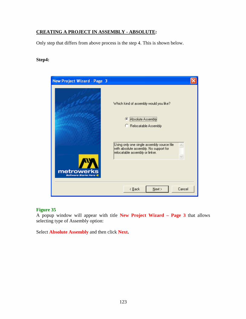
CREATING A PROJECT IN ASSEMBLY - ABSOLUTE: Only step that differs from above process is the step 4. This is shown below. Step4: Figure 35 A popup window will appear with title New Project Wizard – Page 3 that allows selecting type of Assembly option: Select Absolute Assembly and then click Next.