introduction - chegrp5 - homechegrp5.wikispaces.com/file/view/group+5+prelab+6... · web...
TRANSCRIPT
Membrane Air Separation University of Illinois
Membrane Air Separation
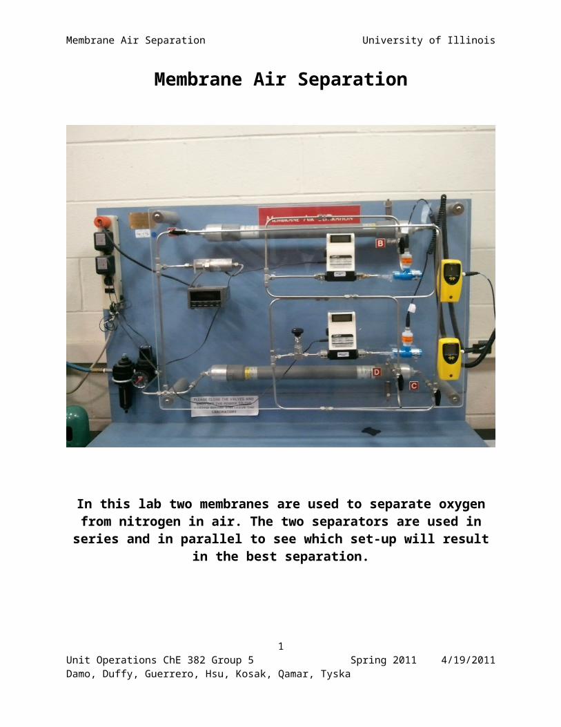
In this lab two membranes are used to separate oxygen from nitrogen in air. The two separators are used in series and in parallel to see which set-up will
result in the best separation.
1Unit Operations ChE 382 Group 5 Spring 2011 4/19/2011Damo, Duffy, Guerrero, Hsu, Kosak, Qamar, Tyska

Membrane Air Separation University of Illinois
Lab Prep Report
Unit Operations II Lab 6
April 19th, 2011
Group 5
Andrew Duffy
Daniyal Qamar
Jeff Tyska
Bernard Hsu
Ryan Kosak
Tomi Damo
Alex Guerrero
2Unit Operations ChE 382 Group 5 Spring 2011 4/19/2011Damo, Duffy, Guerrero, Hsu, Kosak, Qamar, Tyska
Membrane Air Separation University of Illinois
Contents
1. Introduction.........................................................................................................................................4
2. Literature Review/Theory....................................................................................................................5
3. Experimental.....................................................................................................................................10
3.1. Apparatus...................................................................................................................................10
3.2 Materials and Supplies.....................................................................................................................13
3.3 Experimental Procedure.............................................................................................................13
4. Anticipated Results............................................................................................................................15
5. References.........................................................................................................................................16
6. Appendix I: Job Safety Analysis........................................................................................................17
3Unit Operations ChE 382 Group 5 Spring 2011 4/19/2011Damo, Duffy, Guerrero, Hsu, Kosak, Qamar, Tyska
Membrane Air Separation University of Illinois
1. Introduction
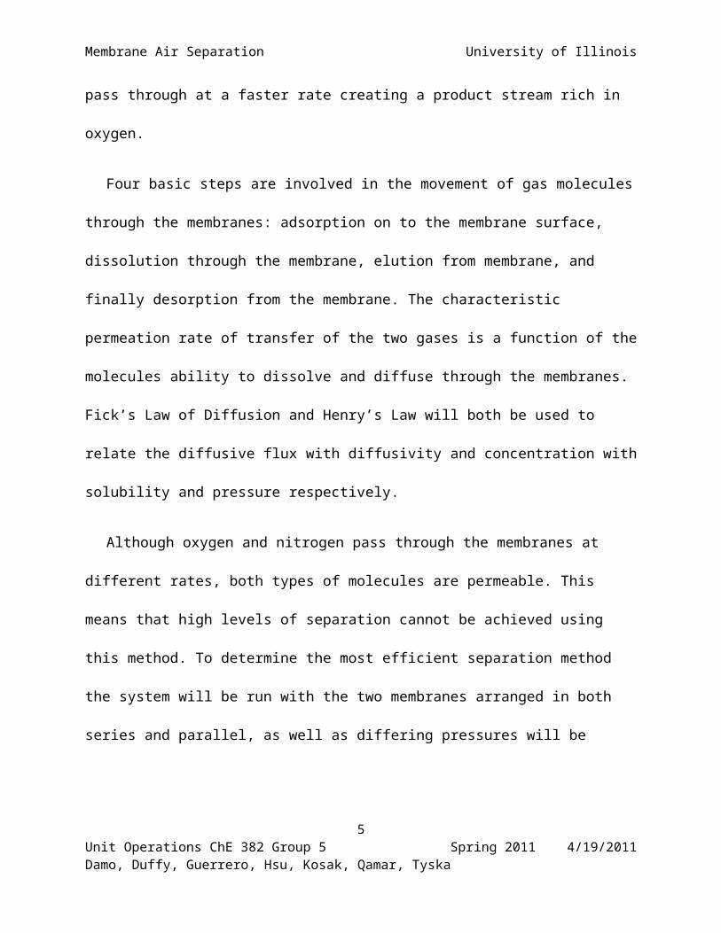
The chemical industry relies heavily on the ability to separate streams into their constitute
components. Distillation, desalination, and membrane separation are among a few of the
methods used. This lab will demonstrate how membrane air separation can be used to achieve the
separation of nitrogen and oxygen from an air feed stream. This method of gas separation has an
industrial advantage of being moderately efficient yet inexpensive.
In this system an air stream will be feed through two permeable polymetric membranes.
Because oxygen and nitrogen each have different relative rates of diffusion through the
membranes, oxygen will selectively be transported through them at a different rate than nitrogen.
The membrane separators (Prism Separator Modules) consist of non-porous hollow fibers which
form a semi-permeable barrier for which the gas molecules must pass through to reach the
product stream. Oxygen is more permeable than nitrogen through the membranes thus oxygen
molecules will pass through at a faster rate creating a product stream rich in oxygen.
Four basic steps are involved in the movement of gas molecules through the membranes:
adsorption on to the membrane surface, dissolution through the membrane, elution from
membrane, and finally desorption from the membrane. The characteristic permeation rate of
transfer of the two gases is a function of the molecules ability to dissolve and diffuse through the
membranes. Fick’s Law of Diffusion and Henry’s Law will both be used to relate the diffusive
flux with diffusivity and concentration with solubility and pressure respectively.
Although oxygen and nitrogen pass through the membranes at different rates, both types of
molecules are permeable. This means that high levels of separation cannot be achieved using this
4Unit Operations ChE 382 Group 5 Spring 2011 4/19/2011Damo, Duffy, Guerrero, Hsu, Kosak, Qamar, Tyska
Membrane Air Separation University of Illinois
method. To determine the most efficient separation method the system will be run with the two
membranes arranged in both series and parallel, as well as differing pressures will be tested.
Separation efficiency can then be determined by taking the ration of the permeation of the two
gases.
2. Literature Review/Theory
Microporous membranes essentially perform as sieves and allow small molecules to
move through the pores while large molecules are blocked (Towler and Sinnot, 562). Membrane
separation works on the basis of relative permeation rates of the components being separated.
Each component transporting through the membrane has a permeation rate that is unique and is a
function of the ability of the component to dissolve and diffuse through the membrane. The two
main relationships for this separation are Fick’s Law (1) which relates diffusion and Henry’s
Law (3) which relates solubility. The gas being separated in this experiment is dry air. This fluid
is assumed to be an ideal binary perfect mixture of oxygen and nitrogen. The permeate in this
experiment is oxygen whereas nitrogen is the retentate. The first relation to show the diffusive
flux through the membrane is expressed by Fick’s Law in equation (1) below.
J i=Di
L∗(C¿1−C¿ 2) (1)
Where:
Ji = Flux of component i in mol/m2s
Di = Diffusivity of component i in m2/s
L = Thickness of membrane in meters
5Unit Operations ChE 382 Group 5 Spring 2011 4/19/2011Damo, Duffy, Guerrero, Hsu, Kosak, Qamar, Tyska
Membrane Air Separation University of Illinois
Cin1 = Concentration of component i inside membrane wall on feed side in mol/m3
Cin2 = Concentration of component i outside the membrane wall on permeate side in mol/m3
The total flux of component i, Ji, can then be calculated.
J i=Qip ρnA
(2)
Where:
Qip = Volumetric flow rate of species i in the permeate in m3/s
ρ = Density of permeate in mol/m3
A = Area of membrane, (in this case 2.7m2 per module)
n = Number of modules used, (in this case 2)
Using equation (1) and (2) the only unknown turns out to be the diffusivity of component i, Di,
which can be solved for when the two equations are equated through the calculated flux of
component i, Ji .
From Henry’s Law.
Cℑ=Si p i (3)
Where:
Cim = Concentration of component i inside the membrane wall in mol/m3
Si = Solubility constant for component i in the membrane in mol/m3Pa
pi = Partial pressure of component i in the gas phase in Pa ( Pascal)
6Unit Operations ChE 382 Group 5 Spring 2011 4/19/2011Damo, Duffy, Guerrero, Hsu, Kosak, Qamar, Tyska
Membrane Air Separation University of Illinois
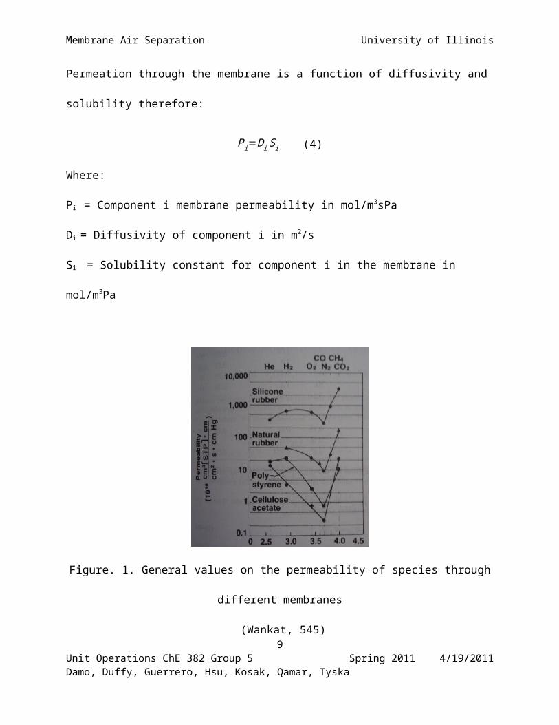
Permeation through the membrane is a function of diffusivity and solubility therefore:
Pi=Di S i (4)
Where:
Pi = Component i membrane permeability in mol/m3sPa
Di = Diffusivity of component i in m2/s
Si = Solubility constant for component i in the membrane in mol/m3Pa
Figure. 1. General values on the permeability of species through different membranes
(Wankat, 545)
The graph above shows permeability’s for oxygen and nitrogen through four types of membranes
calculated at standard pressure and temperature. Using equation (3) and (4) along with the
collected data allows the calculation of the solubility constant for component i in the membrane,
Si.
7Unit Operations ChE 382 Group 5 Spring 2011 4/19/2011Damo, Duffy, Guerrero, Hsu, Kosak, Qamar, Tyska

Membrane Air Separation University of Illinois
Next the separation efficiency can be determined based off of different permeation rates
of the gas components.
α ij=Pi
P j(5)
Where:
αij = Separation factor
Pi = Component i membrane permeability in mol/m3sPa
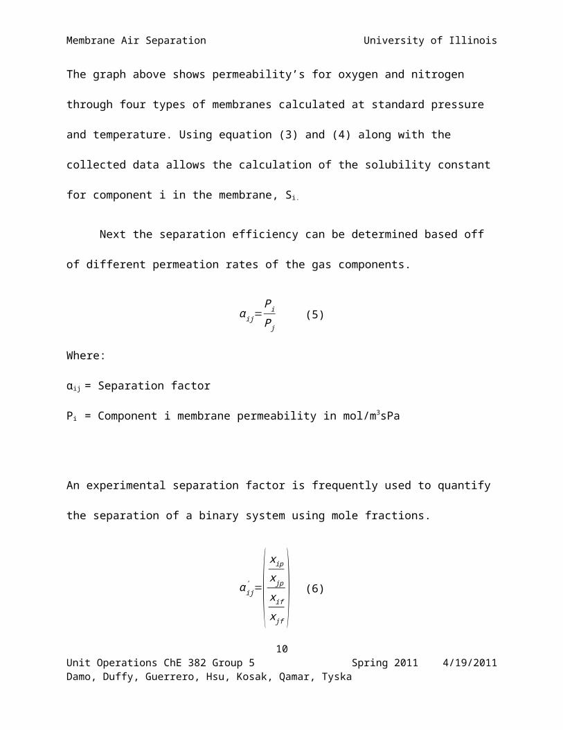
An experimental separation factor is frequently used to quantify the separation of a binary
system using mole fractions.
α ij' =(
x ip
x jp
xif
x jf) (6)
α ij' '=(
x ip
x jp
x if
x jf) (7)
Where:
α’ij = Separation factor based on the non-permeate composition
α’’ij = Separation factor based on feed composition
Next the recovery of oxygen and nitrogen can be determined.8
Unit Operations ChE 382 Group 5 Spring 2011 4/19/2011Damo, Duffy, Guerrero, Hsu, Kosak, Qamar, Tyska
Membrane Air Separation University of Illinois
O2 Recovery=Qp CO2 p
Qf CO2 f(8)
N 2 Recovery=Qr CN 2 r
Qf CN 2 f(9)
Where:
Qp = Volumetric flow rate of permeate in m3/s
Qf = Volumetric flow rate of feed in m3/s
CO2f = Molar concentration of oxygen in feed in mol/m3
CO2p = Molar concentration of oxygen in permeate in mol/m3
CN2f = Molar concentration of nitrogen in feed in mol/m3
CN2r = Molar concentration of oxygen in permeate in mol/m3
Finally the stage cut can be determined which is the fractional amount of the total feed entering
the membrane that passes through as the permeate.
STAGECUT=Q p
Qp+Qf(10)
Where:
Qp = Volumetric flow rate of permeate in m3/s
Qf = Volumetric flow rate of feed in m3/s
9Unit Operations ChE 382 Group 5 Spring 2011 4/19/2011Damo, Duffy, Guerrero, Hsu, Kosak, Qamar, Tyska
Membrane Air Separation University of Illinois
3. Experimental
3.1. Apparatus
Apparatus:
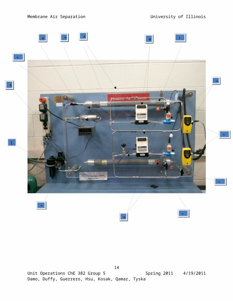
The apparatus could be set up such that the membrane separators would operate in series or in
parallel. The apparatus is shown on the next page.
10Unit Operations ChE 382 Group 5 Spring 2011 4/19/2011Damo, Duffy, Guerrero, Hsu, Kosak, Qamar, Tyska

1
Membrane Air Separation University of Illinois
11Unit Operations ChE 382 Group 5 Spring 2011 4/19/2011Damo, Duffy, Guerrero, Hsu, Kosak, Qamar, Tyska
2
3
5
6 7 84
9
1
1
1
1
1
15 16
Membrane Air Separation University of Illinois
Part No.
Apparatus Use Make/Model Specification Error
1 Air Inlet to Apparatus
- - - -
2 Inlet Manometer Measures the pressure of the inlet air
ARO Max psig: 150Max Temp: 200 F
± 1 psi
3 Power Switch Turns apparatus On/Off - - -4 Membrane Air
separators Separates Oxygen from air Permea – Prism Alpha
Model # PPA-22A0Max psig: 300Max Temp: 150 F
-
5 Oxygen outlet Outlet to the separated oxygen - - -6 Pressure Reader Reads the pressure into the
apparatus, theoretically same pressure as 2
OMEGA - ±1 psi
7 Pressure Transducer
Turns pressure into an electrical signal to be read
- - -
8 Flow Meters Reads the air flow across each of the membranes
TOP TRAK Sierra Instruments Model# 822-13-0VI
Max Psig: 150Units: SLPMRange: 0-10
±.01
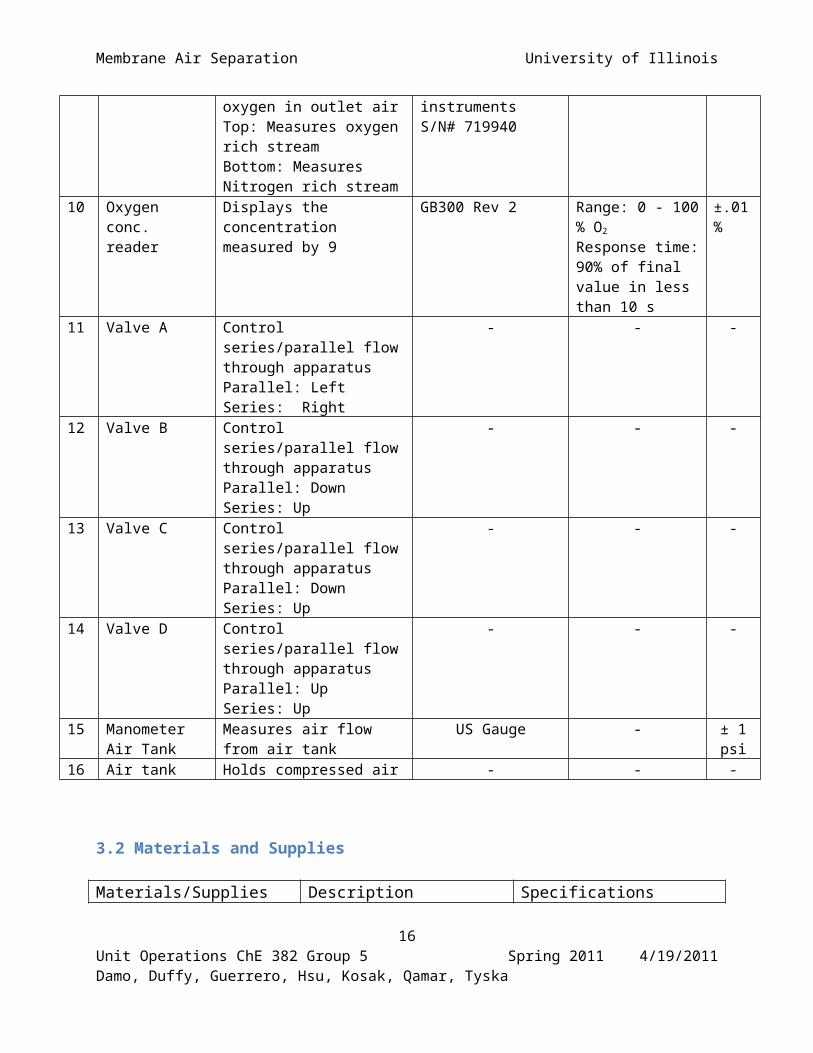
9 Oxygen Sensor Measures the concentration of oxygen in outlet airTop: Measures oxygen rich streamBottom: Measures Nitrogen rich stream
Teledyne analytical instruments S/N# 719940
Class I-17 sensor
10 Oxygen conc. reader
Displays the concentration measured by 9
GB300 Rev 2 Range: 0 - 100 % O2
Response time: 90% of final value in less than 10 s
±.01%
11 Valve A Control series/parallel flow through apparatusParallel: LeftSeries: Right
- - -
12 Valve B Control series/parallel flow through apparatusParallel: Down Series: Up
- - -
13 Valve C Control series/parallel flow through apparatusParallel: DownSeries: Up
- - -
14 Valve D Control series/parallel flow through apparatusParallel: UpSeries: Up
- - -
15 Manometer Air Tank
Measures air flow from air tank
US Gauge - ± 1 psi
16 Air tank Holds compressed air - - -
12Unit Operations ChE 382 Group 5 Spring 2011 4/19/2011Damo, Duffy, Guerrero, Hsu, Kosak, Qamar, Tyska
Membrane Air Separation University of Illinois
3.2 Materials and Supplies
Materials/Supplies Description SpecificationsCompressed Air Compressed air to see the
effects of membrane separation
-
3.3 Experimental Procedure
Start Up Procedure:
1. Turn the power switch on the power strip (3) to the ON position to power up the flow meters
(8), digital pressure reader (6), and oxygen analyzers (9).
2. Allow the oxygen analyzers several minutes to reach a steady reading. Also, the flow meters
may need resetting if there has been a ground fault.
3. Open the valve (near 15) on the compressed air cylinder. Using the cylinder regulator, set
outlet pressure to 140 psig.
4. Set the outlet of the second pressure regulator (near 2) to 100 psig. Do not let it exceed this
pressure.
5. At this point the oxygen analyzers should read a percentage by volume of oxygen near 20.9%
on the sensor display (10). If they do not, gently remove them and slowly wave them in the
air until the sensor displays 20.9%.
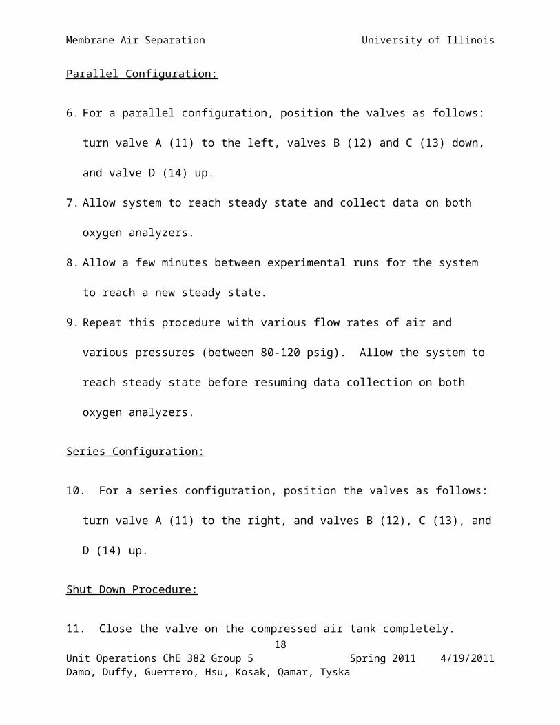
Parallel Configuration:
6. For a parallel configuration, position the valves as follows: turn valve A (11) to the left,
valves B (12) and C (13) down, and valve D (14) up.
7. Allow system to reach steady state and collect data on both oxygen analyzers.
13Unit Operations ChE 382 Group 5 Spring 2011 4/19/2011Damo, Duffy, Guerrero, Hsu, Kosak, Qamar, Tyska
Membrane Air Separation University of Illinois
8. Allow a few minutes between experimental runs for the system to reach a new steady state.
9. Repeat this procedure with various flow rates of air and various pressures (between 80-120
psig). Allow the system to reach steady state before resuming data collection on both oxygen
analyzers.
Series Configuration:
10. For a series configuration, position the valves as follows: turn valve A (11) to the right, and
valves B (12), C (13), and D (14) up.
Shut Down Procedure:
11. Close the valve on the compressed air tank completely.
12. Turn the power switch on the power strip (3) to the OFF position to turn off the flow meters
(8), digital pressure reader (6), and oxygen analyzers (9).
13. Close the valve for the outlet of the second pressure regulator.
14. Clean up the surrounding experiment area.
4. Anticipated Results
The procedure for running this experiment and changing the independent variables is very
simple. The inlet pressures from the air-gas cylinder are varied and the separation method for
the air can be run either in parallel or in series (separation cylinders). Because the purpose of
this experiment is to determine the mass transfer coefficients, the numbers are difficult to
anticipate without some sort of error. It can be anticipated however, that the separation of the 14
Unit Operations ChE 382 Group 5 Spring 2011 4/19/2011Damo, Duffy, Guerrero, Hsu, Kosak, Qamar, Tyska

Membrane Air Separation University of Illinois
oxygen from nitrogen will be greater for the series configuration than for the parallel
configuration. This is because the air will be passing through two different membranes, one after
the other, rather than in parallel, the feed stream will be split and each stream will pass through
the membranes only once, thus leading to lesser of separation as compared to the series
configuration.
While the configuration is one variable to be considered, pressure is a second variable that is
to be considered as well. For higher inlet pressures, the amount of oxygen in the permeate
stream will be greater and the amount of oxygen in the nonpermeate stream will be lower.
Because the driving force for this process is pressure, when pressure increases, more nitrogen
diffuses into the membrane.
The results that can be anticipated from this laboratory are based off of the two independent
variables for the experiment. Placing the membranes in a series configuration will lead to a
greater separation of oxygen from nitrogen due to the fact that a single stream will pass through
two membranes, while in parallel, the feed stream is split and two streams pass through only one
membrane. The second independent variable is that of inlet pressure, where when inlet pressure
is increased, the absorption of nitrogen and the concentration of oxygen in the permeate both
increase. In order to achieve the highest separation of oxygen from nitrogen as possible, a series
configuration with the highest allowable inlet pressure will be used. In order to achieve the
lowest separation of oxygen from this laboratory, a parallel configuration with low inlet pressure
will be used.
15Unit Operations ChE 382 Group 5 Spring 2011 4/19/2011Damo, Duffy, Guerrero, Hsu, Kosak, Qamar, Tyska
Membrane Air Separation University of Illinois
5. References
Bird, R. Byron, Warren E. Stewart, and Edwin N. Lightfoot. Transport Phenomena. New York: J. Wiley, 2007. Print.
Sinnott, Ray, and Gavin Towler. Chemical Engineering Design. Amsterdam: Elsevier, 2009. Print.
W.E. McCabe, J.C. Smith, and P. Harriott 2001. Unit Operations of Chemical Engineering, McGraw Hill, New York.
16Unit Operations ChE 382 Group 5 Spring 2011 4/19/2011Damo, Duffy, Guerrero, Hsu, Kosak, Qamar, Tyska

Membrane Air Separation University of Illinois
6. Appendix I: Job Safety Analysis
What is the purpose of this experiment?
The purpose of this lab is to separate ambient air into two streams concentrated in its two
major components; nitrogen and oxygen. This separation will be achieved using a semi-
permeable membrane in both a series and parallel setup. Data collected during this experiment
will be used to calculate the mass transfer coefficient used in Fick’s law. This value can be used
to determine how effective this apparatus is separating the two components.
What are the hazards associated with the experiment?
High pressure air will be used in this experiment along with sensitive electrical equipment.
Concentrated oxygen streams will be created which may be dangerous to operators due to pure
oxygen’s combustibility.
How will the experiment be conducted in a safe manner?
Eye protection will be worn at all times during this lab for protection from this apparatus and
the neighboring ones. The pressurized air cylinder will be safely secured to the wall and all
valves must be in proper working order. The apparatus must be inspected for any leaks or
damaged piping, fittings, or valves. The main cylinder valve will be shut off when the
experiment is not running. All electronic components will be checked for damage or exposed
(un-insulated) wiring.
17Unit Operations ChE 382 Group 5 Spring 2011 4/19/2011Damo, Duffy, Guerrero, Hsu, Kosak, Qamar, Tyska
Membrane Air Separation University of Illinois
What safety controls are in place?
The majority of this apparatus is cover with Plexiglas shielding to protect the operators. The
pressurized air cylinder is equipped with a blowout valve in case the pressure inside the take
becomes too great. Also, vents are built into the apparatus to exhaust excess pressure.
Describe safe and unsafe ranges of operations.
This system is rated to operate at a maximum pressure of 140 psig. Pressures above this
can damage the membrane. Gas flow rates should be set to around 10−6 square meters/second.
Higher flow rates can also damage the membrane used in this system.
I have read relevant background material for the Unit Operations Laboratory entitled:
Membrane Air Separation and understand the hazards associated with conducting this
experiment. I have planned out my experimental work in accordance to standards and acceptable
safety practices and will conduct all of my experimental work in a careful and safe manner. I
will also be aware of my surroundings, my group members, and other lab students, and will look
out for their safety as well.
18Unit Operations ChE 382 Group 5 Spring 2011 4/19/2011Damo, Duffy, Guerrero, Hsu, Kosak, Qamar, Tyska
Membrane Air Separation University of Illinois
Electronic Signatures:
Bernard Hsu
Daniya l Qamar
Jeff Tyska
Alex Guerrero
Tomi Damo
Ryan Kosak
Andrew Duffy
19Unit Operations ChE 382 Group 5 Spring 2011 4/19/2011Damo, Duffy, Guerrero, Hsu, Kosak, Qamar, Tyska