introduction and tool geometry
TRANSCRIPT

8/3/2019 Introduction and Tool Geometry
http://slidepdf.com/reader/full/introduction-and-tool-geometry 1/29
MEC 4141 MetalCutting : Introduction
Lecturer: Prof. Dr. A.K.M. Nurul AminMME DepartmentTel: 61964482E-mail: [email protected]
8/3/2019 Introduction and Tool Geometry
http://slidepdf.com/reader/full/introduction-and-tool-geometry 2/29
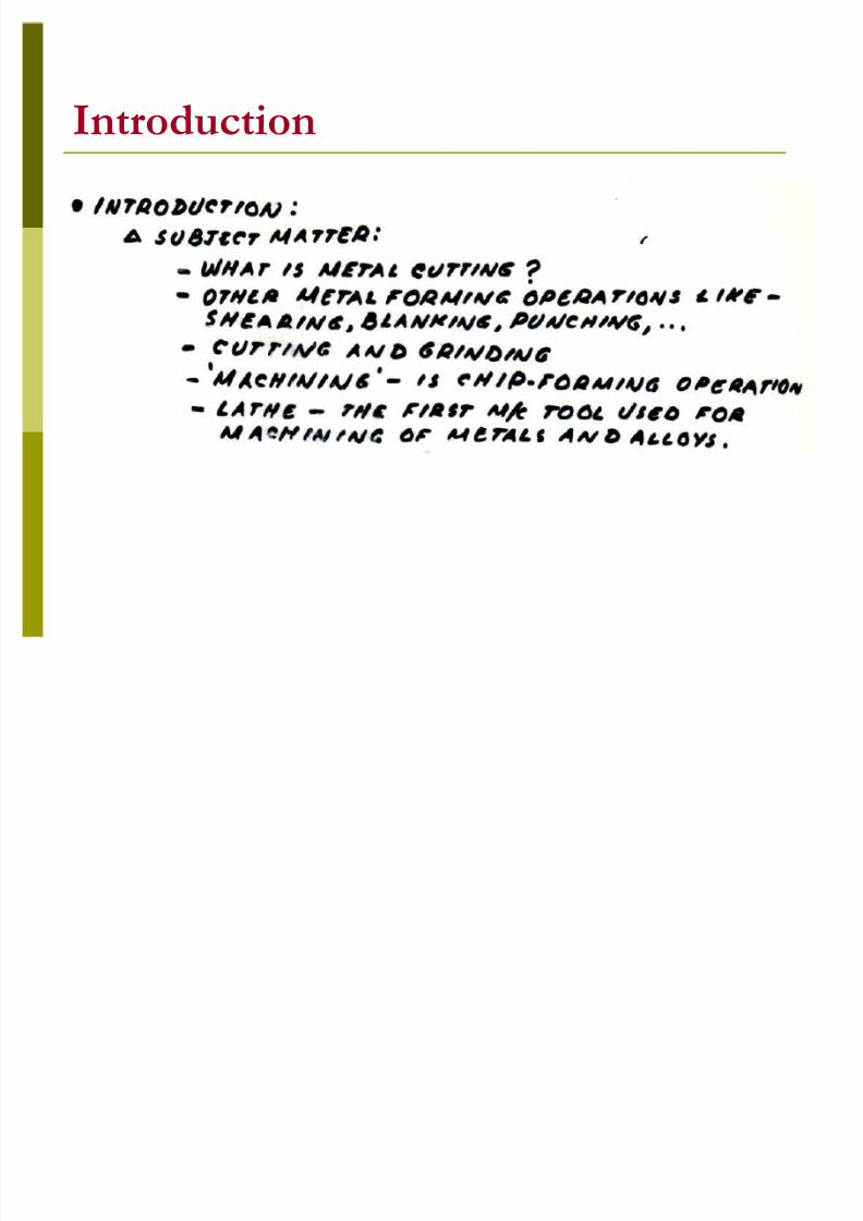
Introduction
8/3/2019 Introduction and Tool Geometry
http://slidepdf.com/reader/full/introduction-and-tool-geometry 3/29
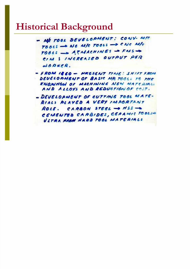
H istorical Background

8/3/2019 Introduction and Tool Geometry
http://slidepdf.com/reader/full/introduction-and-tool-geometry 4/29
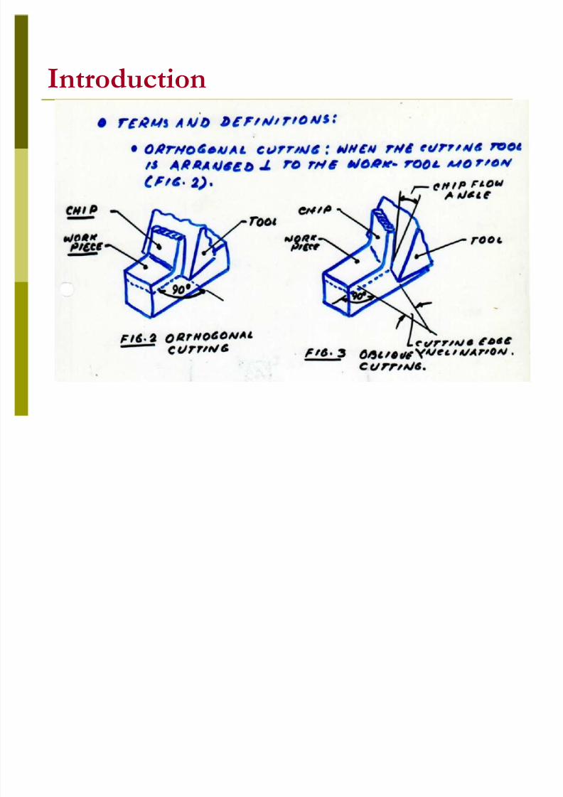
Introduction
8/3/2019 Introduction and Tool Geometry
http://slidepdf.com/reader/full/introduction-and-tool-geometry 5/29
8/3/2019 Introduction and Tool Geometry
http://slidepdf.com/reader/full/introduction-and-tool-geometry 6/29
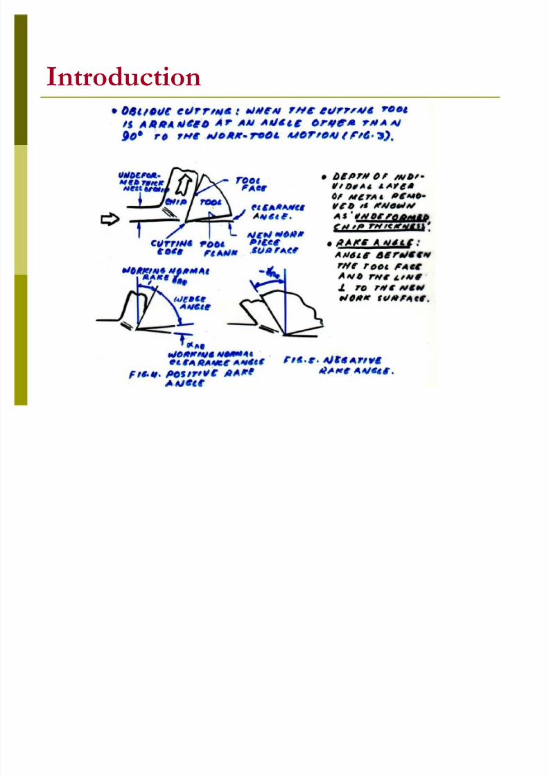
Introduction

8/3/2019 Introduction and Tool Geometry
http://slidepdf.com/reader/full/introduction-and-tool-geometry 7/29
Introduction

8/3/2019 Introduction and Tool Geometry
http://slidepdf.com/reader/full/introduction-and-tool-geometry 8/29
8/3/2019 Introduction and Tool Geometry
http://slidepdf.com/reader/full/introduction-and-tool-geometry 9/29
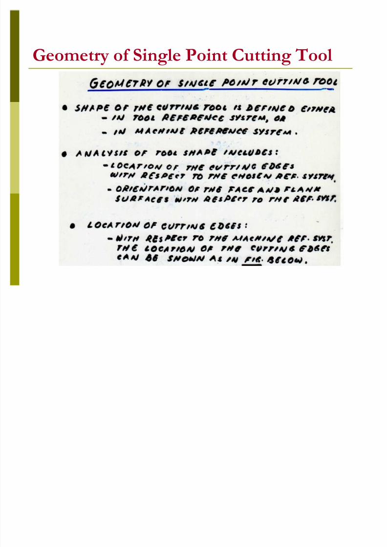
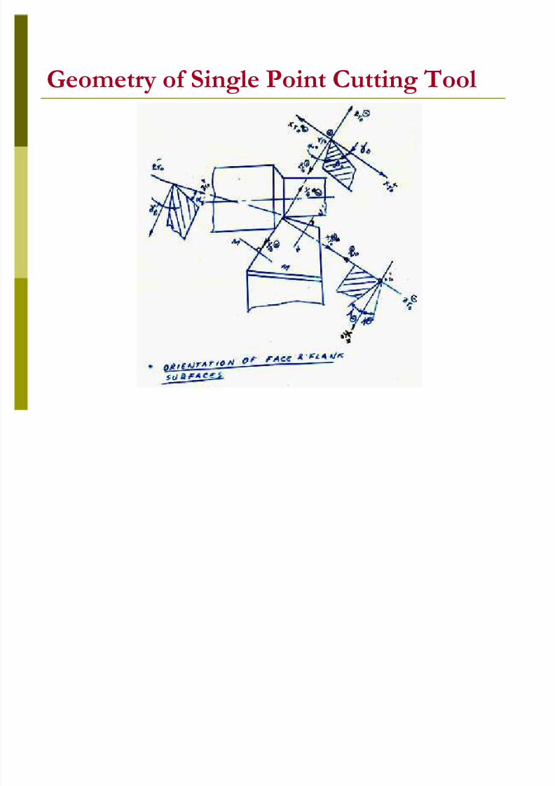
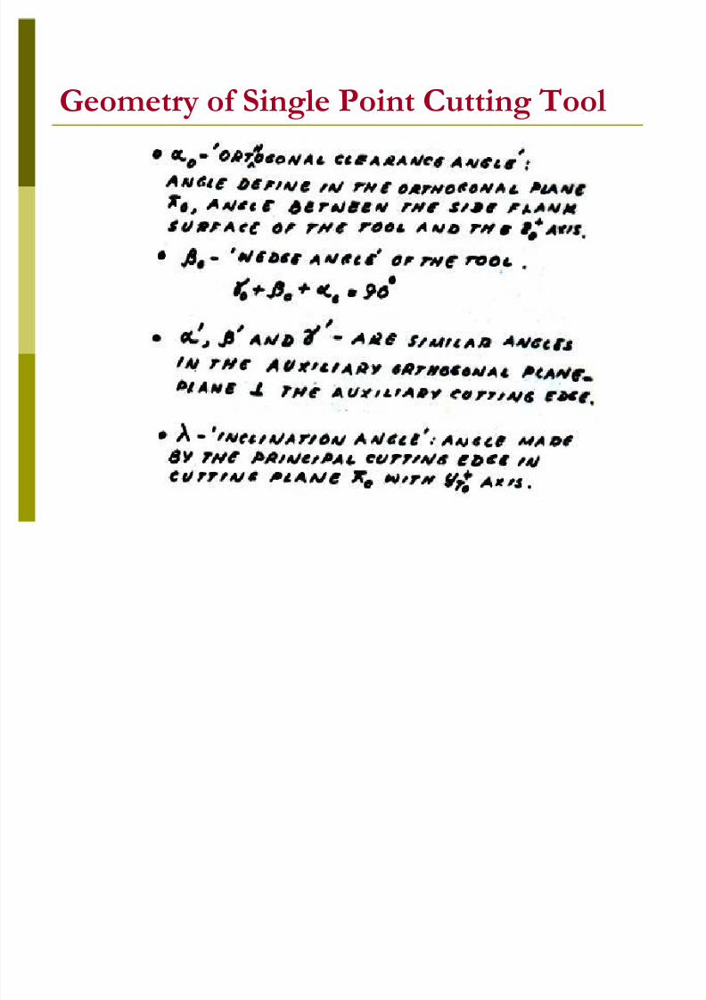
G eometry of Single Point Cutting Tool
8/3/2019 Introduction and Tool Geometry
http://slidepdf.com/reader/full/introduction-and-tool-geometry 10/29
8/3/2019 Introduction and Tool Geometry
http://slidepdf.com/reader/full/introduction-and-tool-geometry 11/29
8/3/2019 Introduction and Tool Geometry
http://slidepdf.com/reader/full/introduction-and-tool-geometry 12/29
G eometry of Single Point Cutting Tool
8/3/2019 Introduction and Tool Geometry
http://slidepdf.com/reader/full/introduction-and-tool-geometry 13/29

8/3/2019 Introduction and Tool Geometry
http://slidepdf.com/reader/full/introduction-and-tool-geometry 14/29
8/3/2019 Introduction and Tool Geometry
http://slidepdf.com/reader/full/introduction-and-tool-geometry 15/29
8/3/2019 Introduction and Tool Geometry
http://slidepdf.com/reader/full/introduction-and-tool-geometry 16/29
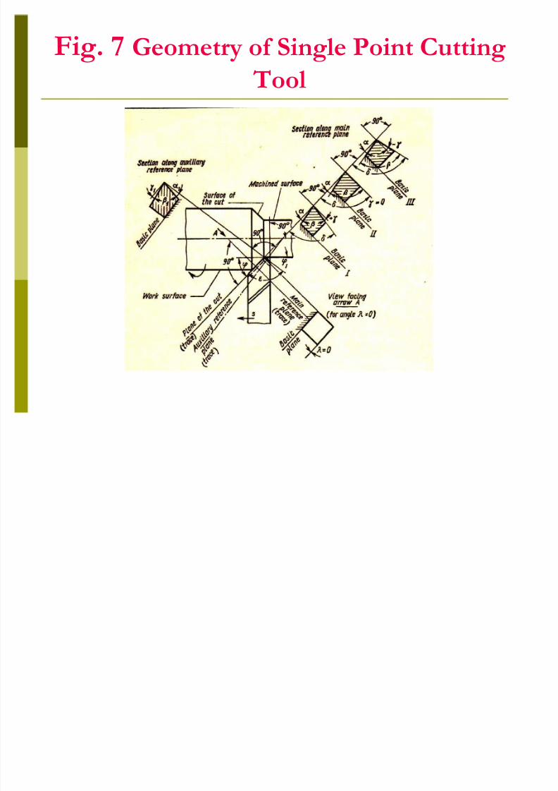
F ig. 7 G eometry of Single Point Cutting Tool
8/3/2019 Introduction and Tool Geometry
http://slidepdf.com/reader/full/introduction-and-tool-geometry 17/29
8/3/2019 Introduction and Tool Geometry
http://slidepdf.com/reader/full/introduction-and-tool-geometry 18/29
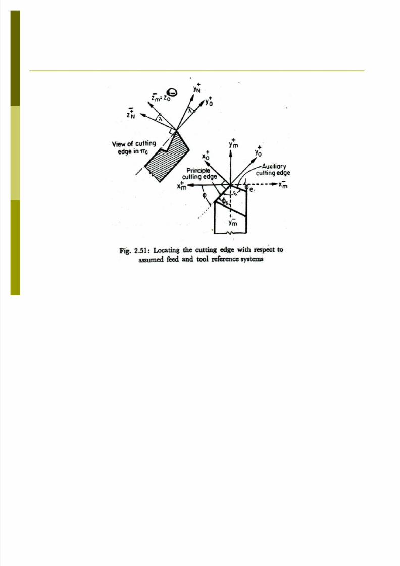
G eometry of Single Point Cutting ToolThe angle of inclination of the side (main)cutting edge is measured the cutting plane Cand is the angle included between the cuttingedge and a line passing through the tool noseparallel to the basic plane R (Figs. 7 and 8). .
8/3/2019 Introduction and Tool Geometry
http://slidepdf.com/reader/full/introduction-and-tool-geometry 19/29
8/3/2019 Introduction and Tool Geometry
http://slidepdf.com/reader/full/introduction-and-tool-geometry 20/29
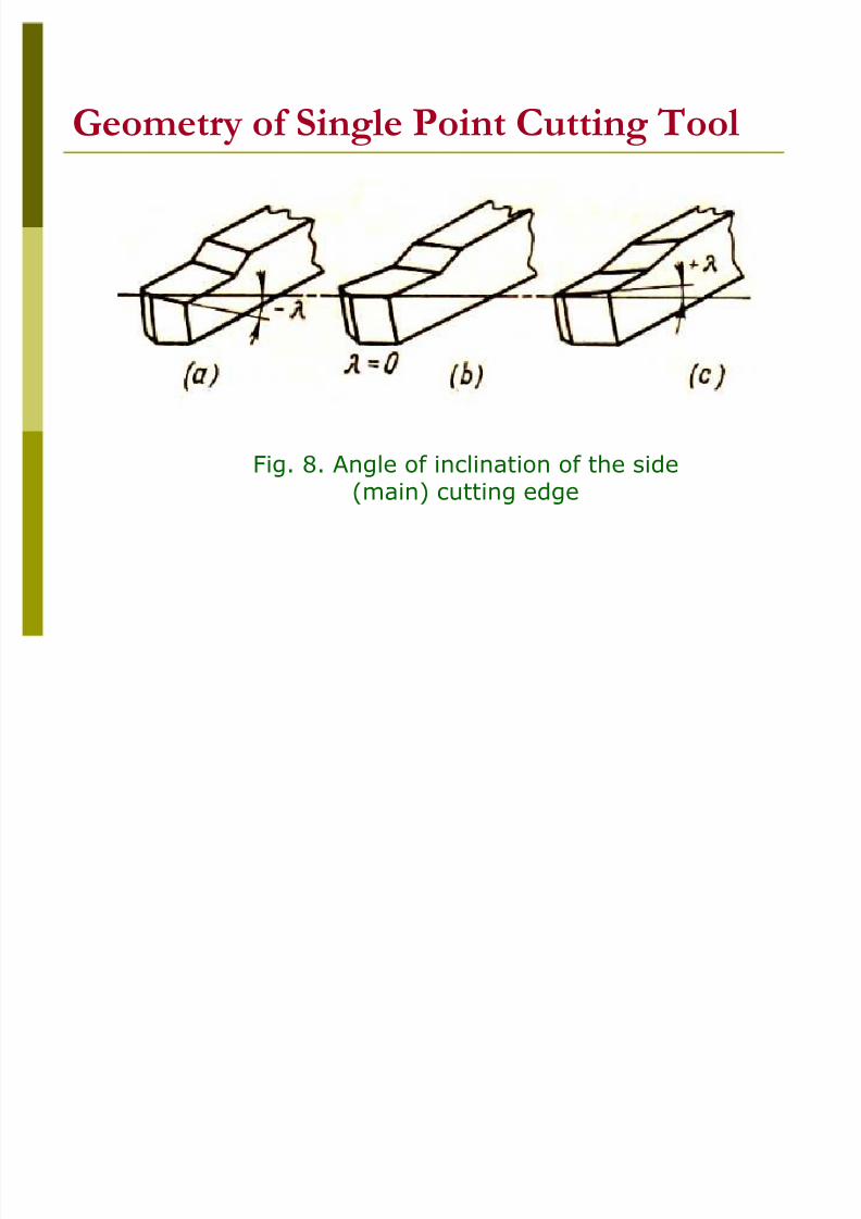
G eometry of Single Point Cutting ToolThe angle of inclination (also called the slopeangle) is considered to be negat iv e if the nose isthe highest point of the cutting edge (Fig. 8 a). Itis equal to z ero if the cutting edge is parallel tothe basic plane (Fig. 8b ) and po si t iv e if the toolnose is the lowest point of the cutting edge (Fig.8c ).

8/3/2019 Introduction and Tool Geometry
http://slidepdf.com/reader/full/introduction-and-tool-geometry 21/29
8/3/2019 Introduction and Tool Geometry
http://slidepdf.com/reader/full/introduction-and-tool-geometry 22/29
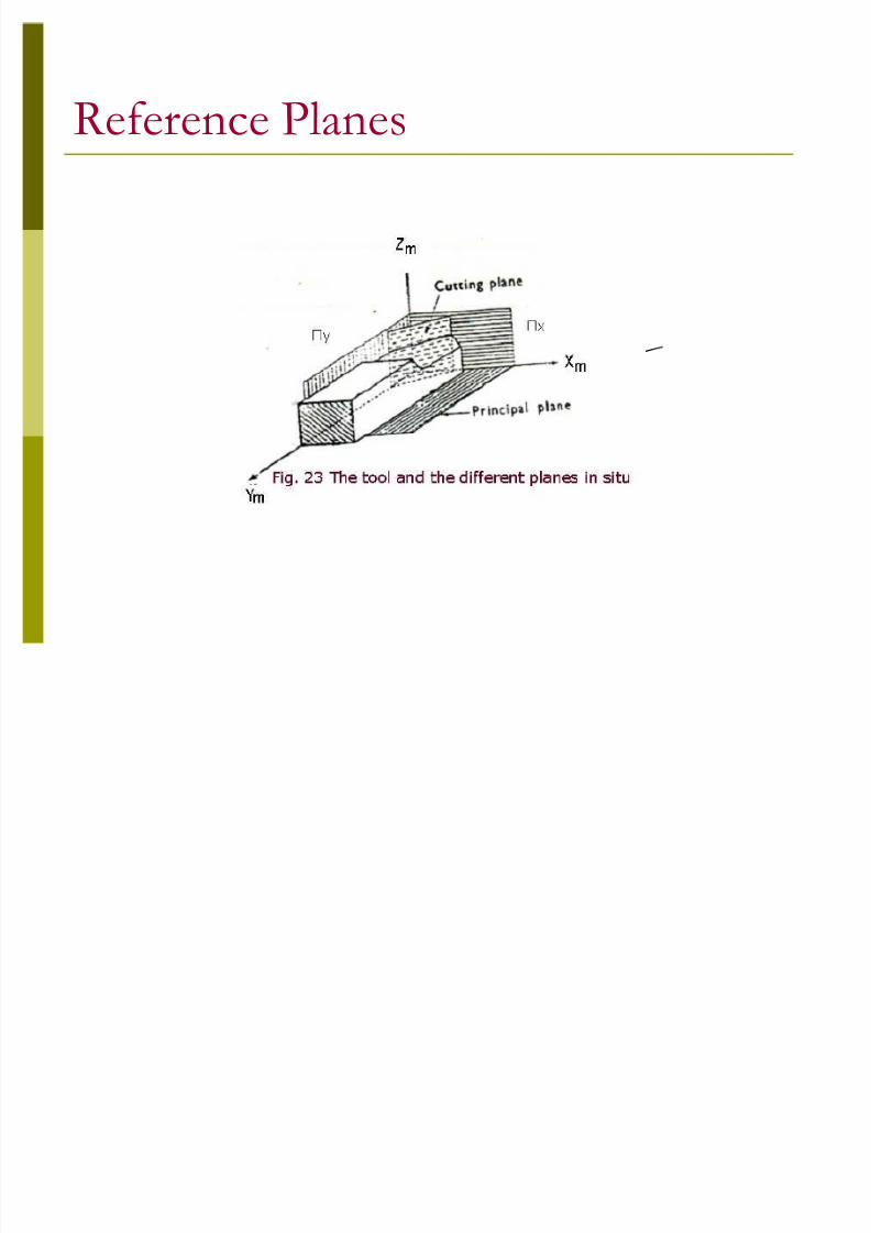
G eometry of Single Point Cutting ToolIn addition to angles and measured in themain reference plane, it is sometimes necessary(for example, in tool grinding and sharpening) torefer to angles which are measured in thelongitudinal (parallel to the tool axis) andtransverse (perpendicular to the tool axis) planesi.e. in the Machine Reference System (Fig. 9).In the longitudinal plane AA ( Y) (Fig. 23), therake and the side (main) flank surface will havethe angles lg and lg , while in the transverseplane BB ( X) (Fig. 23), the angles will be tr and
tr .

8/3/2019 Introduction and Tool Geometry
http://slidepdf.com/reader/full/introduction-and-tool-geometry 23/29
G eometry of Single Point Cutting Tool
Fig. 9 Tool Angles in Longitudinal andTransverse planes
Xm+
Ym+
Zm+
Zm+
8/3/2019 Introduction and Tool Geometry
http://slidepdf.com/reader/full/introduction-and-tool-geometry 24/29
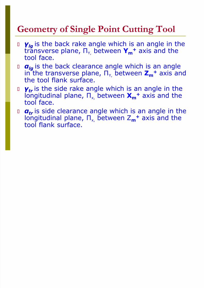
G eometry of Single Point Cutting Tool lg is the back rake angle which is an angle in thetransverse plane, Y, between Y m
+ axis and thetool face.
lg is the back clearance angle which is an anglein the transverse plane, Y, between Z m + axis andthe tool flank surface. tr is the side rake angle which is an angle in thelongitudinal plane, x, between X m
+ axis and thetool face.
tr is side clearance angle which is an angle in thelongitudinal plane, x, between Z m
+ axis and thetool flank surface.
8/3/2019 Introduction and Tool Geometry
http://slidepdf.com/reader/full/introduction-and-tool-geometry 25/29
8/3/2019 Introduction and Tool Geometry
http://slidepdf.com/reader/full/introduction-and-tool-geometry 26/29

8/3/2019 Introduction and Tool Geometry
http://slidepdf.com/reader/full/introduction-and-tool-geometry 27/29
Tool Nomenclature

8/3/2019 Introduction and Tool Geometry
http://slidepdf.com/reader/full/introduction-and-tool-geometry 28/29

8/3/2019 Introduction and Tool Geometry
http://slidepdf.com/reader/full/introduction-and-tool-geometry 29/29