introduction & contents - liniar.co.uk
TRANSCRIPT


Introduction & Contents
For specifications beyond this guidance contact the Liniar Roof Technical Department.
The guidance calculations detailed in this document assess the structure of the conservatory roof, it assumes and assume that the fabrication and installation is carried out in accordance with the Liniar roof current fabrication & installation manuals.
We have provided this information in a series of easy to read tables, illustrating the span capabilities of your individual roof pitch and rafter roof bar spacings.
Please ensure that when using this guidance document all the loading bearing elements, i.e. Eaves Beam, Roof Bars etc. are checked to determine the overall feasibility of the proposed roof assembly.Suitable lateral and vertical support must be provided within the window/wall structure. Liniar can not accept responsibility for the overall stability of the conservatory, unless a portal frame structure is supplied (by others).
When designing a conservatory, careful consideration must be made on the overall stability of the structure that you wish to create. Some roof styles can inadvertently create an unstable structure that has no vertical support at the end of the ridge and may therefore allow potential movement. This is particularly relevant to box gutter applications if a gable fronted roof style is incorporated into the design, please contact the Liniar's Technical Department as your roof maybe unstable. Any unstable roof design must be installed with a portal frame supporting structure.
Please note only conservatories up to 30m² floor area are exempt from Building Regulation approval.
Any designs requiring structual calculations or portal frame structures must be performed by a qualified structural engineer, we do not provide this service and additional charges will be incurred.
Please contact Liniar's Technical Department for guidance on Lantern roof styles
Introduction…
1 Guidance
11
Unsupported Eaves
9 Valleys (Combination Roofs)
7 Victorian Hips (Duopitch)
5 Transom Bars (Duopitch)
3 Transom Bars (Monopitch)
2 Environmental Loadings
12 Structural Supports
10
Tie-Bars
8 Gable Fronts (Duopitch)
6 Edwardian Hips (Duopitch)
4 Hipped Bars (Monopitch)
Contents…

1.1 - Guidance ...
15°
25°
35°
25°
Duopitch Roof Pitch Range…
Wallplate Pitch Range : 2.5°to 14°Half Ridge Pitch Range : 15°to 40°
Monopitch Roof Pitch Range…
Ridge Pitch Range : 15°to 40°
Limitations …
The maximum pitch differential over a hip bar should be no greater than 10°, this rule applies to hipped roof styles
191m
m
90m
m
The minimum length of ridge for a duopitch roof is 191mm, any ridge greater should extend beyond the first set of
rafters by a minimum of 90mm
380mm
A minimum ridge length of 380mm should be
applied to double hipped roofs and must have at
least one set of rafters to support the ridge
The minimum length of the supporting eaves beam should be no less than 400mm
If the style constitutes a non-return valley (Victorian facets) assembly, the design will be only made available in
POLYCARBONATE glazing and WILL NOT be supplied in Glass
400mm
400mm
PolyONLY
Unsuitable applications …
We regret Gazebo styles will beunavailable until further notice
Gable fronted styles without a supporting host wall are deemed unstable, they unable to withstand environemental forces acting on the gable ends and will allow movement of the ridge. These
styles will only be made available if a supporting portal frame is specified
Ga
ble
Fra
me
Ga
ble
Fra
me
Ga
ble
Fra
me
Environmental force
Environmental force Environmental force
Environmental force
Please check the feasibility of the conservatory before proceeding
minimumreturn of eaves
RidgeRidge
Ridge
See section 9 for maximum valley lengths
Edwardian's Victorian's Gable Front'sStandard Lean-To's Hipped Lean-To's
Min pitchfor a HippedLean-To : 5°
Non-returnValley
Po
lyca
rbo
na
te O
nly

1.2 - How to use the guide
We have presented loading information into a series of tables, illustrating the span capabilities of your individual roof pitch and rafter/roof bar spacing's. It is essential that when you are assessing the feasibility of a conservatory structure all loadbearing elements are checked for suitability
There are many factors that need to be considered when assessing the feasibility of a conservatory roof layout. The first step of any conservatory design is to define the Envirnomental Loadings for the specific site installation. We have collated typical geographical data for the majority of UK based cities and tabulated this information in Section 2 of this guide. Basic Snow Loading values are determined from the regional map, where loadings above 0.6 Kn/m² are shown in grey shade. Consult the Liniar Roof Techinical Department regarding regions greater than 0.8 Kn/m².
see Section 2 for Environmental Loading
Step 2 : Transom Bars ...
The Transom bar loading capabilities are dependent on the style of the roof. Section 3 of this guide has been allocated for Monopitch (Lean-to) style roofs, illustrating how far they travel in plan for a single span. Whilst Section 5 has been allocated for Duopitch (with a Ridge) style roofs, illustrating how far they travel in plan for a double span. Having determined the environmental loading requirements in Step 1, use the look up charts to determine the loading capabilities of the proposed roof bar. Simply determine the intended glazing material, along with the proposed roof pitch and intended rafter.
Step 1 : Environmental Loadings ...
Step 3 : Remaining Bars ...
The overall span of the conservatory is not determined solely on the performance of the Transom bars, this is determined mainly by the style of a roof. Allowable deflection limits on Hip Bars will reduce the span of a Georgian roof whilst the addition and contribution of imposed wind loadings will have an influence on a Gable Fronted configuration. Please refer to the relevant configuration elements in Section 4 and Section's 6 to 8 of this guide. Again, all information is detailed and defined by the glazing material, loadings and roof pitches.
Step 4 : Load Bearing Elements ...
see Section 4 for Monopitch bars
The remaining sections within this guidance document covers Tie Bar requirements, Valley span checks, Eaves Beam Spans & Load Bearing Capacities of the proposed bay pole product range (check with the wall/window frame supplier).
see Section's 6 to 8 for Duopitch bars
see Section 9 for Valleys
see Section10 for unsupported Eaves
see Section 3 for Monopitch bars
see Section 5 for Duopitch bars
see Section 11 for Tie-bars
see Section 12 for Structural Supports

Key:
Vb - Basic Wind Speed (taken from BS 6399:Pt 2)
Units (m/s)
Dist - Closest distance to the Sea (approximate values)
Units (Km)
Vb Dist Vb Dist
Aberdeen 24.3 0 Leeds 23.3 88
Abergavenny 21.0 78 Leicester 21.5 114
Aberystwyth 22.6 0 Lincoln 23.1 54
Berwick-upon-Tweed 24.8 0 Lisburn 23.9 25
Birmingham 20.4 152 Liverpool 22.3 16
Blackburn 22.8 38 Llandrindod Wells 21.5 62
Bournemouth 21.6 0 Llandundo 23.3 0
Bradford 23.2 84 Luton 21.0 115
Brighton 22.0 2 Maidstone 21.6 42
Bristol 20.6 86 Manchester 22.3 55
Burton-on-Trent 21.4 134 Middlesborough 24.7 10
Cambridge 22.5 80 Milton Keyes 20.8 135
Cardiff 21.3 4 Newcastle-upon-Tyne 24.8 15
Carlisle 24.1 58 Newry 23.0 25
Chatham 21.5 20 Northampton 21.3 150
Chelmsford 21.9 33 Norwich 24.5 27
Chester 21.8 30 Nottingham 22.0 96 Vb Dist
Coventry 20.5 158 Oxford 19.7 108 Armagh 23.5 10
Colchester 22.7 13 Perth 22.8 48 Ballymena 24.2 27
Croydon 20.9 64 Peterborough 22.6 78 Ballymoney 24.7 18
Dagenham 21.3 54 Peterhead 24.8 0 Bangor 24.2 1
Darlington 24.6 29 Plymouth 23.0 3 Belfast 24.0 1
Derby 21.6 118 Preston 22.9 23 Coleraine 25.0 25
Dorchester 21.7 10 Reading 19.8 82 Drogheda 23.0 2
Dumfries 23.7 37 Redhill - Surrey 21.0 50 Enniskillen 23.7 1
Dundee 23.5 0 Salisbury 20.9 38 Londonderry 25.0 8
Edinburgh 23.5 3 Sheffield 22.5 102 Omagh 24.0 50
Enfield 20.8 59 Shrewsbury 21.2 80
Exeter 22.2 16 Southampton 21.2 2
Falkirk 23.0 78 Southend-on-Sea 21.7 0
Glasgow 23.7 86 St Albans 20.7 104
Gloucester 19.9 136 Stevenage 21.4 110 Vb Dist
Guildford 20.9 58 Stoke-on-Trent 21.4 84 Antrim 23.9 1
Harrow 20.3 86 Sutton 20.7 60 Athlone 23.5 110
Hastings 22.2 0 Swansea 22.3 2 Cork 24.3 20
Hereford 20.4 114 Swindon 19.7 96 Dublin 23.0 5
High Wycombe 19.9 91 Taunton 21.5 21 Galway 24.3 2
Huddersfield 22.8 84 Telford 21.0 98 Limerick 24.0 65
Inverness 24.1 2 Tonbridge 21.5 43 Waterford 23.8 10
Ipswich 23.2 17 Uxbridge 20.0 82
Kilmarnock 24.0 13 Wakefield 23.2 90
Kingston-upon-Thames 20.5 68 Warrington 22.0 40
Kingston-upon-Hull 24.0 0 Watford 20.5 80
Kirkcaldy 23.3 0 Worcester 20.0 142
Lancaster 23.8 5 York 23.9 56
Great Britain…
Republic of Ireland…
Basic Snow Load Map…
Scotland (Additional Guidance)…
Northern Ireland…
For specifications in the 1.0 kN/m² snow loading region please contact the Liniar Roof's Technical Department.
For specifications beyond this guidance contact the Liniar Roof's Technical
2.1 - Environmental Loadings

600 650 700 750 800 850 900 950 1000 600 650 700 750 800 850 900 950 1000
5° 2838 2763 2695 2633 2577 2525 2477 2424 2390 2336 2274 2218 2167 2120 2077 2037 2000 1965
10° 2815 2741 2673 2612 2556 2504 2457 2412 2371 2316 2254 2198 2147 2101 2058 2019 1982 1947
15° 2777 2703 2637 2577 2521 2470 2423 2379 2338 2281 2220 2165 2115 2070 2026 1988 1952 1918
20° 2723 2651 2586 2527 2473 2423 2376 2333 2293 2233 2173 2119 2071 2026 1984 1946 1911 1878
25° 2654 2584 2521 2463 2410 2361 2316 2274 2235 2171 2112 2060 2013 1969 1929 1892 1857 1825
30° 2570 2502 2441 2385 2334 2287 2243 2202 2164 2095 2039 1988 1942 1900 1861 1825 1792 1761
35° 2470 2405 2346 2292 2243 2198 2156 2117 2080 2005 1951 1903 1859 1818 1781 1747 1715 1685
40° 2355 2293 2237 2185 2138 2095 2055 2018 1983 1901 1850 1804 1762 1724 1689 1656 1626 1598
5° 2594 2526 2463 2407 2355 2307 2263 2222 2184 2172 2114 2062 2014 1970 1930 1893 1858 1826
10° 2572 2505 2444 2387 2336 2289 2245 2204 2166 2153 2096 2044 1997 1953 1913 1877 1842 1810
15° 2539 2472 2411 2355 2305 2258 2215 2174 2137 2122 2065 2014 1967 1925 1886 1849 1815 1784
20° 2490 2424 2365 2310 2260 2215 2172 2133 2096 2078 2023 1972 1927 1885 1846 1811 1778 1747
25° 2428 2364 2305 2252 2204 2159 2118 2079 2043 2021 1967 1919 1874 1834 1796 1761 1729 1699
30° 2352 2289 2233 2181 2134 2091 2051 2014 1979 1952 1900 1853 1810 1771 1734 1701 1670 1641
35° 2261 2201 2147 2098 2052 2011 1972 1936 1903 1871 1820 1775 1734 1696 1662 1630 1600 1572
40° 2157 2099 2048 2000 1957 1918 1881 1847 1815 1776 1728 1685 1646 1610 1577 1547 1518 1492
1.6
600 650 700 750 800 850 900 950 1000 600 650 700 750 800 850 900 950 1000
5° 4541 4421 4312 4213 4123 4040 3963 3878 3824 3738 3638 3549 3467 3392 3323 3259 3200 3144
10° 4504 4386 4277 4179 4090 4006 3931 3859 3794 3706 3606 3517 3435 3362 3293 3230 3171 3115
15° 4443 4325 4219 4123 4034 3952 3877 3806 3741 3650 3552 3464 3384 3312 3242 3181 3123 3069
20° 4357 4242 4138 4043 3957 3877 3802 3733 3669 3573 3477 3390 3314 3242 3174 3114 3058 3005
25° 4246 4134 4034 3941 3856 3778 3706 3638 3576 3474 3379 3296 3221 3150 3086 3027 2971 2920
30° 4112 4003 3906 3816 3734 3659 3589 3523 3462 3352 3262 3181 3107 3040 2978 2920 2867 2818
35° 3952 3848 3754 3667 3589 3517 3450 3387 3328 3208 3122 3045 2974 2909 2850 2795 2744 2696
40° 3768 3669 3579 3496 3421 3352 3288 3229 3173 3042 2960 2886 2819 2758 2702 2650 2602 2557
5° 4150 4042 3941 3851 3768 3691 3621 3555 3494 3475 3382 3299 3222 3152 3088 3029 2973 2922
10° 4115 4008 3910 3819 3738 3662 3592 3526 3466 3445 3354 3270 3195 3125 3061 3003 2947 2896
15° 4062 3955 3858 3768 3688 3613 3544 3478 3419 3395 3304 3222 3147 3080 3018 2958 2904 2854
20° 3984 3878 3784 3696 3616 3544 3475 3413 3354 3325 3237 3155 3083 3016 2954 2898 2845 2795
25° 3885 3782 3688 3603 3526 3454 3389 3326 3269 3234 3147 3070 2998 2934 2874 2818 2766 2718
30° 3763 3662 3573 3490 3414 3346 3282 3222 3166 3123 3040 2965 2896 2834 2774 2722 2672 2626
35° 3618 3522 3435 3357 3283 3218 3155 3098 3045 2994 2912 2840 2774 2714 2659 2608 2560 2515
40° 3451 3358 3277 3200 3131 3069 3010 2955 2904 2842 2765 2696 2634 2576 2523 2475 2429 2387
Roof P
itch u
p to
En
vir
on
men
tal S
no
w L
oad
ing
0.6
kN
/m²
Reg
ion
s
Roof P
itch u
p to
0.8
kN
/m²
Reg
ion
s
En
vir
on
men
tal S
no
w L
oad
ing
25 & 32mm Polycarbonate 24mm IGU (4/16/4mm Glazing)
0.8
kN
/m²
Reg
ion
s
Roof P
itch u
p to
Max Rafter Ctr up to (mm) Max Rafter Ctr up to (mm)
25 & 32mm Polycarbonate
Roof P
itch u
p to
0.6
kN
/m²
Reg
ion
s
24mm IGU (4/16/4mm Glazing)Max Rafter Ctr up to (mm) Max Rafter Ctr up to (mm)
Max span in PLAN = Internal frame projection
3.1 - Std Transom Bars (Monopitch Roofs)
Std Transom ...
Note: Values shown are maximum distances each glazing bar can span in PLAN, they are NOT the length of
the rafter!
Bolstered Std Transom ...
Rafter Ctr (max 1000mm)
LZAL0061
LZAL0061
LZAL0072

600 650 700 750 800 850 900 950 1000 600 650 700 750 800 850 900 950 1000
5° 3349 3262 3182 3110 3044 2983 2926 2874 2825 2760 2687 2621 2561 2506 2456 2409 2365 2325
10° 3322 3235 3157 3085 3019 2959 2903 2851 2802 2736 2664 2598 2539 2484 2434 2388 2344 2304
15° 3277 3191 3114 3043 2978 2919 2863 2813 2764 2695 2624 2560 2501 2447 2398 2352 2310 2270
20° 3214 3130 3054 2985 2921 2863 2808 2758 2711 2638 2568 2505 2448 2396 2347 2302 2261 2222
25° 3133 3051 2977 2909 2847 2790 2738 2688 2643 2565 2497 2436 2380 2329 2282 2238 2198 2160
30° 3033 2954 2882 2817 2757 2702 2651 2603 2559 2475 2410 2351 2297 2248 2202 2160 2121 2084
35° 2916 2840 2771 2708 2650 2597 2548 2502 2460 2369 2307 2250 2199 2151 2108 2068 2030 1995
40° 2780 2707 2642 2582 2527 2476 2429 2386 2345 2247 2188 2134 2085 2040 1999 1961 1924 1892
5° 3063 2983 2910 2843 2782 2726 2675 2626 2582 2567 2499 2438 2382 2330 2283 2239 2199 2161
10° 3039 2959 2886 2821 2760 2703 2652 2604 2561 2545 2477 2416 2360 2310 2263 2220 2180 2142
15° 2998 2919 2848 2783 2723 2668 2618 2570 2526 2508 2441 2381 2327 2277 2230 2188 2148 2111
20° 2941 2863 2793 2730 2671 2611 2568 2521 2478 2456 2391 2332 2279 2229 2184 2142 2104 2067
25° 2868 2792 2723 2661 2604 2552 2503 2458 2416 2389 2326 2269 2217 2169 2125 2084 2045 2011
30° 2777 2704 2638 2578 2525 2472 2425 2381 2340 2308 2247 2191 2141 2095 2052 2013 1977 1942
35° 2670 2600 2537 2479 2426 2377 2332 2290 2250 2211 2153 2100 2052 2007 1965 1929 1894 1861
40° 2547 2480 2419 2364 2314 2267 2224 2184 2147 2100 2044 1994 1948 1906 1867 1831 1798 1767
1.45
600 650 700 750 800 850 900 950 1000 600 650 700 750 800 850 900 950 1000
5° 4856 4730 4614 4510 4414 4325 4243 4167 4096 4002 3896 3800 3713 3634 3561 3493 3429 3371
10° 4817 4691 4578 4473 4378 4291 4209 4134 4063 3967 3863 3767 3682 3602 3529 3463 3399 3341
15° 4752 4627 4515 4412 4318 4233 4151 4079 4008 3908 3805 3712 3626 3548 3477 3410 3350 3292
20° 4660 4539 4428 4328 4235 4151 4072 3999 3931 3825 3724 3632 3550 3474 3403 3338 3278 3222
25° 4543 4424 4317 4218 4128 4046 3970 3898 3832 3719 3621 3532 3451 3377 3309 3245 3187 3132
30° 4398 4283 4179 4085 3998 3918 3844 3774 3711 3589 3495 3409 3331 3260 3193 3132 3075 3022
35° 4228 4118 4018 3927 3843 3766 3695 3628 3567 3435 3345 3263 3189 3119 3057 2999 2944 2893
40° 4031 3925 3831 3744 3664 3590 3522 3460 3400 3258 3173 3094 3023 2958 2899 2843 2790 2743
5° 4441 4325 4220 4122 4034 3953 3879 3808 3744 3722 3624 3535 3454 3379 3310 3247 3189 3133
10° 4407 4291 4185 4090 4002 3919 3845 3776 3713 3690 3592 3503 3422 3350 3281 3219 3161 3106
15° 4347 4233 4130 4035 3948 3869 3796 3727 3663 3637 3539 3452 3374 3302 3234 3173 3115 3061
20° 4264 4151 4050 3959 3873 3786 3724 3655 3593 3561 3467 3381 3305 3232 3167 3106 3051 2997
25° 4159 4048 3948 3858 3776 3700 3629 3564 3503 3464 3373 3290 3215 3145 3081 3022 2965 2916
30° 4027 3921 3825 3738 3661 3584 3516 3452 3393 3347 3258 3177 3104 3038 2975 2919 2867 2816
35° 3872 3770 3679 3595 3518 3447 3381 3321 3263 3206 3122 3045 2975 2910 2849 2797 2746 2698
40° 3693 3596 3508 3428 3355 3287 3225 3167 3113 3045 2964 2891 2825 2764 2707 2655 2607 2562
24mm IGU (4/16/4mm Glazing)
25 & 32mm Polycarbonate 24mm IGU (4/16/4mm Glazing)Max Rafter Ctr up to (mm) Max Rafter Ctr up to (mm)
En
vir
on
men
tal S
no
w L
oad
ing
0.6
kN
/m²
Reg
ion
s
Roof P
itch u
p to
0.8
kN
/m²
Reg
ion
s
25 & 32mm Polycarbonate
Roof P
itch u
p to
Max Rafter Ctr up to (mm) Max Rafter Ctr up to (mm)
Roof P
itch u
p to
En
vir
on
men
tal S
no
w L
oad
ing
0.6
kN
/m²
Reg
ion
s
Roof P
itch u
p to
0.8
kN
/m²
Reg
ion
s
HD Transom ...
3.2 - HD Transom Bars (Monopitch Roofs)
Bolstered HD Transom ...
Max span in PLAN = Internal frame projection
Note: Values shown are maximum distances each glazing bar can span in PLAN, they are NOT the length of
the rafter! Rafter Ctr (max 1000mm)
LZAL0062
LZAL0062
LZAL0072

600 650 700 750 800 850 900 950 1000 600 650 700 750 800 850 900 950 1000
5° 4086 3981 3887 3800 3721 3648 3580 3517 3458 3374 3287 3208 3135 3069 3008 2952 2899 2850
10° 4053 3949 3855 3770 3691 3618 3551 3488 3430 3344 3258 3179 3108 3042 2982 2926 2874 2825
15° 3998 3895 3803 3718 3641 3569 3503 3441 3383 3294 3209 3132 3062 2997 2937 2882 2831 2783
20° 3920 3820 3729 3646 3570 3500 3436 3375 3318 3225 3141 3066 2997 2934 2875 2821 2770 2724
25° 3821 3723 3635 3552 3480 3412 3348 3289 3234 3130 3054 2981 2934 2852 2795 2743 2694 2648
30° 3699 3605 3519 3441 3370 3303 3242 3185 3132 3013 2947 2876 2852 2753 2698 2647 2600 2556
35° 3554 3464 3382 3307 3239 3175 3116 3061 3010 2875 2819 2753 2691 2635 2582 2534 2489 2447
40° 3388 3311 3224 3153 3083 3027 2971 2919 2870 2715 2663 2611 2552 2499 2449 2403 2360 2320
5° 3743 3646 3558 3478 3405 3338 3276 3217 3163 3141 3043 2985 2917 2859 2799 2746 2697 2651
10° 3712 3617 3530 3450 3378 3311 3249 3191 3137 3114 3033 2959 2892 2831 2774 2722 2673 2628
15° 3661 3568 3482 3403 3332 3266 3205 3148 3095 3069 2989 2916 2850 2790 2734 2682 2634 2590
20° 3591 3499 3416 3339 3269 3203 3144 3083 3036 3005 2927 2856 2791 2732 2678 2627 2580 2536
25° 3502 3412 3330 3255 3187 3123 3065 3011 2960 2924 2847 2779 2716 2658 2605 2556 2510 2467
30° 3391 3304 3225 3153 3087 3025 2969 2916 2867 2824 2750 2684 2623 2567 2516 2469 2425 2383
35° 3261 3177 3101 3032 2967 2909 2855 2803 2757 2706 2635 2572 2514 2460 2411 2366 2323 2284
40° 3109 3030 2956 2891 2835 2775 2723 2675 2630 2569 2502 2442 2387 2336 2290 2247 2207 2163
1.34
600 650 700 750 800 850 900 950 1000 600 650 700 750 800 850 900 950 1000
5° 5475 5335 5209 5092 4986 4888 4797 4713 4634 4521 4405 4299 4201 4112 4031 3956 3885 3819
10° 5431 5292 5166 5052 4946 4848 4758 4674 4596 4481 4366 4260 4165 4076 3996 3921 3851 3786
15° 5357 5219 5096 4982 4879 4782 4694 4611 4533 4414 4300 4197 4103 4016 3936 3862 3794 3729
20° 5253 5119 4997 4886 4784 4690 4604 4523 4446 4322 4209 4108 4016 3932 3853 3780 3712 3650
25° 5120 4989 4871 4760 4663 4572 4486 4407 4334 4194 4092 3995 3932 3822 3745 3676 3610 3548
30° 4957 4831 4715 4611 4516 4426 4344 4268 4197 4037 3949 3854 3822 3689 3615 3547 3484 3425
35° 4762 4642 4532 4431 4340 4255 4175 4102 4033 3853 3777 3689 3606 3531 3460 3396 3335 3279
40° 4540 4437 4320 4225 4131 4056 3981 3911 3846 3638 3568 3499 3420 3349 3282 3220 3162 3109
5° 5016 4886 4768 4661 4563 4473 4390 4311 4238 4209 4078 4000 3909 3831 3751 3680 3614 3552
10° 4974 4847 4730 4623 4527 4437 4354 4276 4204 4173 4064 3965 3875 3794 3717 3647 3582 3522
15° 4906 4781 4666 4560 4465 4376 4295 4218 4147 4112 4005 3907 3819 3739 3664 3594 3530 3471
20° 4812 4689 4577 4474 4380 4292 4213 4131 4068 4027 3922 3827 3740 3661 3589 3520 3457 3398
25° 4693 4572 4462 4362 4271 4185 4107 4035 3966 3918 3815 3724 3639 3562 3491 3425 3363 3306
30° 4544 4427 4322 4225 4137 4054 3978 3907 3842 3784 3685 3597 3515 3440 3371 3308 3250 3193
35° 4370 4257 4155 4063 3976 3898 3826 3756 3694 3626 3531 3446 3369 3296 3231 3170 3113 3061
40° 4166 4060 3961 3874 3799 3719 3649 3585 3524 3442 3353 3272 3199 3130 3069 3011 2957 2898
24mm IGU (4/16/4mm Glazing)
25 & 32mm Polycarbonate 24mm IGU (4/16/4mm Glazing)Max Rafter Ctr up to (mm) Max Rafter Ctr up to (mm)
En
vir
on
men
tal S
no
w L
oad
ing
0.6
kN
/m²
Reg
ion
s
Roof P
itch u
p to
0.8
kN
/m R
eg
ion
s
25 & 32mm Polycarbonate
Roof P
itch u
p to
Max Rafter Ctr up to (mm) Max Rafter Ctr up to (mm)
Roof P
itch u
p to
En
vir
on
men
tal S
no
w L
oad
ing
0.6
kN
/m²
Reg
ion
s
Roof P
itch u
p to
0.8
kN
/m R
eg
ion
s
XHD Transom ...
Bolstered XHD Transom ...
3.3 - XHD Transom Bars (Monopitch Roofs)
Max span in PLAN = Internal frame projection
Note: Values shown are maximum distances each glazing bar can span in PLAN, they are NOT the length of
the rafter! Rafter Ctr (max 1000mm)
LZAL0063B
LZAL0063B
LZAL0072

Max length of hip in plan = Angle of hip in plan view =
Length = √ ( Span² + Projection² ) Tan c° = ( Span / Projection )
or Length = ( Span / sin c° )
or Length = ( Projection / cos c° )
5° 10° 15° 20° 25° 30° 35° 40°
5° 45.00 63.61 71.92
Span (to half D-Ring) = 10° 26.39 45.00 56.65 64.15
Span = √ ( Length² - Projection² ) 15° 18.08 33.35 45.00 53.64 60.12
or Span = ( Length * sin c° ) 20° 25.85 36.36 45.00 52.03 57.77
or Span = ( Projection * tan c° ) 25° 29.88 37.97 45.00 51.07 56.34
30° 32.23 38.93 45.00 50.49 55.47
35° 33.66 39.51 45.00 50.16
40° 34.53 39.84 45.00
Projection =
Projection = √ ( Length² - Span² )
or Projection = ( Length * cos c° )
or Projection = ( Span / tan c° )
Minimum roof pitch for Monopitch = 5°
Minimum roof pitch for Duopitch = 15°
Maximum roof pitch (a & b) = 40°
Minimum roof pitch for Monopitch = 5°
Minimum roof pitch for Duopitch = 15°
Maximum roof pitch (a & b) = 35°
Maximum pitch differential = 9°
Angle ' c '
Roof pitch ' a ' (for Monopitch roofs)
Roof pitch ' a ' (for Duopitch roofs)
Roof pitch 'b
' (fo
r M
onopitch's
)
Roof pitch 'b
' (fo
r D
uopitch's
)
Note: Should the maximum span of the conservatory equal or exceed 6000mm (5200mm for Edwardian in glass), a portal frame structure must be installed (Please consult a Structural Engineer for further guidance). Values shown are maximum distances the valley can span in PLAN, they are NOT the length of the valley!
Max length of hip in plan (L) = √ (S²+P²)
Span (S) = Width to half D-Ring
Length (L)
Pro
jectio
n (
P)
Hip Length in plan ... Angle c in plan ...
Span (roof a) ...
Projection (roof b) ...
4.1 - Hipped Lean-To Bars (Monopitch Roofs)
c°
Projection (P)
Span (S)
Roof pitch 'a' Roof pitch 'b'

`
5° 10° 15° 20° 25° 30° 35° 40° 5° 10° 15° 20° 25° 30° 35° 40°
5° 3232 3273 3328 3018 3056 3107
10° 3273 3220 3230 3259 3056 3005 3013 3039
15° 3328 3230 3202 3199 3214 3107 3013 2985 2980 2993
20° 3259 3199 3176 3166 3170 3039 2980 2956 2943 2945
25° 3214 3166 3141 3124 3120 2993 2943 2918 2898 2892
30° 3170 3124 3094 3072 3061 2945 2898 2867 2841 2828
35° 3120 3072 3038 3008 2892 2841 2806 2772
40° 3061 3008 2967 2828 2772 2730
5° 3025 3065 3117 2865 3273 2951
10° 3065 3015 3025 3051 3273 2854 2862 2887
15° 3117 3025 2998 2995 3010 2951 2862 2836 2832 2844
20° 3051 2995 2841 2965 2970 2887 2832 2810 2797 2800
25° 3010 2965 2942 2927 2924 2844 2797 2775 2756 2751
30° 2970 2927 2901 2879 2820 2800 2756 2730 2703 2693
35° 2924 2879 2976 2820 2751 2703 2672 2642
40° 2820 2820 2783 2693 2642 2602
1.19
5° 10° 15° 20° 25° 30° 35° 40° 5° 10° 15° 20° 25° 30° 35° 40°
5° 3846 3895 3960 3591 3637 3697
10° 3895 3832 3844 3878 3637 3576 3585 3616
15° 3960 3844 3810 3807 3825 3697 3585 3552 3546 3562
20° 3878 3807 3779 3768 3772 3616 3546 3518 3502 3505
25° 3825 3768 3738 3718 3713 3562 3502 3472 3449 3441
30° 3772 3718 3682 3656 3643 3505 3449 3412 3381 3365
35° 3713 3656 3615 3580 3441 3381 3339 3299
40° 3643 3580 3531 3365 3299 3249
5° 3600 3647 3709 3409 3895 3512
10° 3647 3588 3600 3631 3895 3396 3406 3436 `
15° 3709 3600 3568 3564 3582 3512 3406 3375 3370 3384
20° 3631 3564 3381 3528 3534 3436 3370 3344 3328 3332
25° 3582 3528 3501 3483 3480 3384 3328 3302 3280 3274
30° 3534 3483 3452 3426 3356 3332 3280 3249 3217 3205
35° 3480 3426 3541 3356 3274 3217 3180 3144
40° 3356 3356 3312 3205 3144 3096
En
vir
om
en
tal S
no
w L
oad
ing
En
vir
on
men
tal S
no
w L
oad
ing
0.6
kN
/m²
Reg
ion
s
Roof P
itch 'A
' up to
0.8
kN
/m²
Reg
ion
s
Roof P
itch 'A
' up to
0.6
kN
/m²
Reg
ion
s
Roof P
itch 'A
' up to
0.8
kN
/m²
Reg
ion
s
25 & 32mm Polycarbonate 24mm IGU (4/16/4mm Glazing)
Roof P
itch 'A
' up to
Roof Pitch ' B ' up toRoof Pitch ' B ' up to
25 & 32mm Polycarbonate
Roof Pitch ' B ' up to Roof Pitch ' B ' up to
24mm IGU (4/16/4mm Glazing)
Span (S)
P
Note: Values shown are maximum Length of Hip Bar can span in PLAN, they are NOT the
length of the Hip !
Max length of hip (L) = √ (S²+P²)
Pro
jectio
n
S
Std Hip Bar ...
L
LZAL0003
LZAL0003
LZAL0072
Bolstered Std Hip Bar ...
4.2 - Std Hipped Lean-To Bars (Monopitch Roofs)

`
5° 10° 15° 20° 25° 30° 35° 40° 5° 10° 15° 20° 25° 30° 35° 40°
5° 3584 3630 3690 3348 3391 3346
10° 3630 3571 3583 3613 3391 3335 3342 3371
15° 3690 3583 3551 3548 3564 3346 3342 3312 3307 3319
20° 3613 3548 3523 3510 3516 3371 3307 3280 3265 3268
25° 3564 3510 3483 3464 3462 3319 3265 3237 3216 3208
30° 3516 3464 3432 3407 3396 3268 3216 3182 3154 3138
35° 3462 3407 3369 3336 3208 3154 3113 3077
40° 3396 3336 3291 3138 3077 3028
5° 3356 3400 3457 3178 3221 3273
10° 3400 3345 3355 3385 3221 3167 3175 3202
15° 3457 3355 3326 3323 3339 3273 3175 3147 3142 3155
20° 3385 3323 3299 3290 3294 3202 3142 3117 3104 3107
25° 3339 3290 3264 3247 3244 3155 3104 3077 3059 3053
30° 3294 3247 3217 3194 3184 3107 3059 3028 3002 2988
35° 3244 3194 3159 3129 3053 3002 2966 2931
40° 3184 3129 3087 2988 2931 2888
1.17
5° 10° 15° 20° 25° 30° 35° 40° 5° 10° 15° 20° 25° 30° 35° 40°
5° 4193 4247 4317 3917 3967 3915
10° 4247 4178 4192 4227 3967 3902 3910 3944
15° 4317 4192 4155 4151 4170 3915 3910 3875 3869 3883
20° 4227 4151 4122 4107 4114 3944 3869 3838 3820 3824
25° 4170 4107 4075 4053 4051 3883 3820 3787 3763 3753
30° 4114 4053 4015 3986 3973 3824 3763 3723 3690 3671
35° 4051 3986 3942 3903 3753 3690 3642 3600
40° 3973 3903 3850 3671 3600 3543
5° 3927 3978 4045 3718 3769 3829
10° 3978 3914 3925 3960 3769 3705 3715 3746
15° 4045 3925 3891 3888 3907 3829 3715 3682 3676 3691
20° 3960 3888 3860 3849 3854 3746 3676 3647 3632 3635
25° 3907 3849 3819 3799 3795 3691 3632 3600 3579 3572
30° 3854 3799 3764 3737 3725 3635 3579 3543 3512 3496
35° 3795 3737 3696 3661 3572 3512 3470 3429
40° 3725 3661 3612 3496 3429 3379
Roof P
itch 'A
' up to
En
vir
on
men
tal S
no
w L
oad
ing
0.6
kN
/m²
Reg
ion
s
Roof P
itch 'A
' up to
0.8
kN
/m²
Reg
ion
s
Roof P
itch 'A
' up to
En
vir
on
men
tal S
no
w L
oad
ing
0.6
kN
/m²
Reg
ion
s
Roof P
itch 'A
' up to
0.8
kN
/m²
Reg
ion
s
Roof Pitch ' B ' up to Roof Pitch ' B ' up to
25 & 32mm Polycarbonate 24mm IGU (4/16/4mm Glazing)Roof Pitch ' B ' up to Roof Pitch ' B ' up to
25 & 32mm Polycarbonate 24mm IGU (4/16/4mm Glazing)
Span (S)
P
Max length of hip (L) = √ (S²+P²)
Pro
jectio
n
S
L
Bolstered HD Hip Bar
...
HD Hip Bar ...
LZAL0007
LZAL0007
LZAL0072
4.3 - HD Hipped Lean-To Bars (Monopitch Roofs)
Note: Values shown are maximum Length of Hip Bar can span in PLAN, they are NOT the
length of the Hip !

`
5° 10° 15° 20° 25° 30° 35° 40° 5° 10° 15° 20° 25° 30° 35° 40°
5° 3968 4009 4061 3719 3768 3829
10° 4009 3953 3960 3987 3768 3705 3714 3746
15° 4061 3960 3927 3921 3931 3829 3714 3680 3675 3689
20° 3987 3921 3891 3873 3873 3746 3675 3645 3629 3632
25° 3931 3873 3840 3815 3806 3689 3629 3596 3573 3566
30° 3873 3815 3776 3743 3724 3632 3573 3536 3505 3488
35° 3806 3743 3695 3652 3566 3505 3459 3419
40° 3724 3652 3596 3488 3419 3343
5° 3729 3778 3839 3533 3579 3636
10° 3778 3717 3729 3761 3579 3520 3529 3559
15° 3839 3729 3697 3694 3710 3636 3529 3497 3492 3506
20° 3761 3694 3667 3655 3660 3559 3492 3465 3451 3454
25° 3710 3655 3628 3608 3605 3506 3451 3421 3400 3393
30° 3660 3608 3575 3550 3537 3454 3400 3366 3336 3322
35° 3605 3550 3512 3471 3393 3336 3295 3259
40° 3537 3471 3418 3322 3259 3209
1.14
5° 10° 15° 20° 25° 30° 35° 40° 5° 10° 15° 20° 25° 30° 35° 40°
5° 4524 4570 4630 4240 4296 4365
10° 4570 4506 4514 4545 4296 4224 4234 4270
15° 4630 4514 4477 4470 4481 4365 4234 4195 4190 4205
20° 4545 4470 4436 4415 4415 4270 4190 4155 4137 4140
25° 4481 4415 4378 4349 4339 4205 4137 4099 4073 4065
30° 4415 4349 4305 4267 4245 4140 4073 4031 3996 3976
35° 4339 4267 4212 4163 4065 3996 3943 3898
40° 4245 4163 4099 3976 3898 3811
5° 4251 4307 4376 4028 4080 4145
10° 4307 4237 4251 4288 4080 4013 4023 4057
15° 4376 4251 4215 4211 4229 4145 4023 3987 3981 3997
20° 4288 4211 4180 4167 4172 4057 3981 3950 3934 3938
25° 4229 4167 4136 4113 4110 3997 3934 3900 3876 3868
30° 4172 4113 4076 4047 4032 3938 3876 3837 3803 3787
35° 4110 4047 4004 3957 3868 3803 3756 3715
40° 4032 3957 3897 3787 3715 3658
En
vir
on
men
tal S
no
w L
oad
ing
0.6
kN
/m²
Reg
ion
s
Roof P
itch 'A
' up to
0.8
kN
/m²
Reg
ion
s
Roof Pitch ' B ' up to
25 & 32mm Polycarbonate
25 & 32mm Polycarbonate
24mm IGU (4/16/4mm Glazing)Roof Pitch ' B ' up to
Roof P
itch 'A
' up to
24mm IGU (4/16/4mm Glazing)Roof Pitch ' B ' up to Roof Pitch ' B ' up to
Roof P
itch 'A
' up to
En
vir
on
men
tal S
no
w L
oad
ing
0.6
kN
/m²
Reg
ion
s
Roof P
itch 'A
' up to
0.8
kN
/m²
Reg
ion
sSpan (S)
P
Max length of hip (L) = √ (S²+P²)
Pro
jectio
n
S
L
Bolstered XHD Hip Bar ...
XHD Hip Bar ...
LZAL0033
LZAL0033
LZAL0072
4.4 - XHD Hipped Lean-To Bars (Monopitch Roofs)
Note: Values shown are maximum Length of Hip Bar can span in PLAN, they are NOT the
length of the Hip !

600 650 700 750 800 850 900 950 1000 600 650 700 750 800 850 900 950 1000
15° 5004 4895 4793 4698 4608 4524 4444 4369 4297 4580 4459 4349 4249 4158 4073 3995 3923 3855
20° 4958 4853 4755 4663 4576 4495 4418 4345 4276 4484 4365 4257 4159 4070 3987 3911 3840 3773
25° 4875 4775 4681 4593 4511 4433 4359 4289 4222 4359 4243 4139 4044 3956 3876 3802 3733 3668
30° 4759 4665 4577 4494 4416 4342 4272 4205 4142 4207 4095 3994 3902 3818 3741 3669 3602 3540
35° 4612 4524 4442 4365 4292 4222 4157 4094 4035 4027 3920 3823 3735 3654 3580 3511 3449 3388
40° 4430 4350 4275 4204 4137 4074 4013 3956 3901 3819 3717 3625 3542 3465 3395 3330 3269 3212
15° 4647 4536 4432 4336 4246 4162 4083 4008 3937 4252 4138 4036 3943 3857 3779 3706 3638 3575
20° 4615 4508 4408 4315 4228 4146 4069 3997 3928 4163 4053 3952 3861 3777 3700 3629 3563 3501
25° 4549 4446 4350 4261 4177 4099 4025 3955 3888 4051 3943 3845 3756 3675 3600 3530 3466 3406
30° 4453 4356 4265 4180 4100 4025 3955 3888 3824 3912 3808 3713 3628 3549 3477 3410 3347 3289
35° 4328 4237 4152 4073 3998 3927 3860 3797 3737 3748 3648 3558 3476 3400 3331 3265 3207 3151
40° 4173 4090 4011 3938 3868 3803 3741 3682 3626 3559 3464 3378 3300 3228 3162 3101 3044 2991
1.6
600 650 700 750 800 850 900 950 1000 600 650 700 750 800 850 900 950 1000
15° 6000 6000 6000 6000 6000 6000 6000 6000 6000 6000 6000 6000 6000 6000 6000 6000 6000 6000
20° 6000 6000 6000 6000 6000 6000 6000 6000 6000 6000 6000 6000 6000 6000 6000 6000 6000 6000
25° 6000 6000 6000 6000 6000 6000 6000 6000 6000 6000 6000 6000 6000 6000 6000 6000 5973 5869
30° 6000 6000 6000 6000 6000 6000 6000 6000 6000 6000 6000 6000 6000 6000 5986 5870 5763 5664
35° 6000 6000 6000 6000 6000 6000 6000 6000 6000 6000 6000 6000 5976 5846 5728 5618 5518 5421
40° 6000 6000 6000 6000 6000 6000 6000 6000 6000 6000 5947 5800 5667 5544 5432 5328 5230 5139
15° 6000 6000 6000 6000 6000 6000 6000 6000 6000 6000 6000 6000 6000 6000 6000 6000 6000 6000
20° 6000 6000 6000 6000 6000 6000 6000 6000 6000 6000 6000 6000 6000 6000 5920 5806 5701 5602
25° 6000 6000 6000 6000 6000 6000 6000 6000 6000 6000 6000 6000 6000 5880 5760 5648 5546 5450
30° 6000 6000 6000 6000 6000 6000 6000 6000 6000 6000 6000 5941 5805 5678 5563 5456 5355 5262
35° 6000 6000 6000 6000 6000 6000 6000 6000 5979 5997 5837 5693 5562 5440 5330 5224 5131 5042
40° 6000 6000 6000 6000 6000 6000 5986 5891 5802 5694 5542 5405 5280 5165 5059 4962 4870 4786
24mm IGU (4/16/4mm Glazing)
25 & 32mm Polycarbonate 24mm IGU (4/16/4mm Glazing)Max Rafter Crs up to (mm) Max Rafter Crs up to (mm)
En
vir
on
men
tal S
no
w L
oad
ing
0.6
kN
/m²
Re
gio
ns
Roof P
itch u
p to
0.8
kN
/m²
Re
gio
ns
25 & 32mm Polycarbonate
Roof P
itch u
p to
Max Rafter Crs up to (mm) Max Rafter Crs up to (mm)
Roof P
itch u
p to
En
vir
on
men
tal S
no
w L
oad
ing
0.6
kN
/m²
Re
gio
ns
Roof P
itch u
p to
0.8
kN
/m²
Re
gio
ns
5.1 - Std Transom Bars (Duopitch Roofs)
Bolstered Std Transom ...
LZAL0061
LZAL0061
LZAL0072
Max internalwidth between Eaves
Note: Values shown are maximum span distances between Eaves Beams, they are NOT the length of the rafter!
It should be noted that the capabilities of the Transom bars are illustrated below, however all loading bearing elements must be checked to determine the overall feasibility of the proposed roof assembly. This may reduce the size and the limitations of the conservatory, see relevant style sections and remaining component elements!
for Victorian Hips ...
See Section 7
for Edwardian Hips ...
See Section 6
for Tie-Bars ...
See Section 9
for Edwardian Hips ...
See Section 8
Rafter Ctr (max 1000mm)
Std Transom ...

600 650 700 750 800 850 900 950 1000 600 650 700 750 800 850 900 950 1000
15° 5992 5873 5761 5656 5556 5463 5374 5289 5209 5408 5266 5137 5020 4913 4814 4723 4637 4558
20° 5925 5814 5707 5606 5511 5420 5335 5254 5176 5294 5155 5029 4914 4809 4712 4623 4540 4462
25° 5819 5711 5609 5513 5422 5337 5255 5177 5103 5148 5012 4890 4778 4676 4582 4495 4414 4338
30° 5669 5568 5473 5383 5298 5217 5140 5066 4996 4968 4837 4719 4612 4513 4422 4338 4260 4187
35° 5480 5387 5299 5216 5137 5052 4990 4922 4848 4756 4631 4518 4415 4320 4233 4153 4078 4008
40° 5249 5165 5085 5010 4938 4869 4804 4741 4682 4511 4393 4285 4187 4097 4015 3938 3867 3801
15° 5599 5476 5361 5253 5152 5056 4966 4881 4801 5023 4890 4770 4661 4561 4468 4383 4304 4230
20° 5553 5434 5324 5220 5122 5030 4943 4861 4783 4920 4789 4672 4565 4467 4376 4293 4215 4142
25° 5464 5351 5245 5146 5053 4965 4882 4803 4728 4786 4660 4545 4441 4345 4258 4176 4101 4030
30° 5339 5232 5132 5039 4950 4867 4788 4713 4641 4623 4501 4390 4290 4197 4112 4034 3961 3892
35° 5177 5078 4985 4898 4815 4737 4663 4593 4510 4430 4313 4207 4110 4022 3941 3865 3795 3730
40° 4976 4887 4802 4722 4637 4543 4457 4377 4302 4207 4096 3995 3903 3819 3742 3670 3604 3541
1.45
600 650 700 750 800 850 900 950 1000 600 650 700 750 800 850 900 950 1000
15° 6000 6000 6000 6000 6000 6000 6000 6000 6000 6000 6000 6000 6000 6000 6000 6000 6000 6000
20° 6000 6000 6000 6000 6000 6000 6000 6000 6000 6000 6000 6000 6000 6000 6000 6000 6000 6000
25° 6000 6000 6000 6000 6000 6000 6000 6000 6000 6000 6000 6000 6000 6000 6000 6000 6000 6000
30° 6000 6000 6000 6000 6000 6000 6000 6000 6000 6000 6000 6000 6000 6000 6000 6000 6000 6000
35° 6000 6000 6000 6000 6000 6000 6000 6000 6000 6000 6000 6000 6000 6000 6000 6000 5913 5812
40° 6000 6000 6000 6000 6000 6000 6000 6000 6000 6000 6000 6000 6000 5941 5822 5710 5607 5511
15° 6000 6000 6000 6000 6000 6000 6000 6000 6000 6000 6000 6000 6000 6000 6000 6000 6000 6000
20° 6000 6000 6000 6000 6000 6000 6000 6000 6000 6000 6000 6000 6000 6000 6000 6000 6000 6000
25° 6000 6000 6000 6000 6000 6000 6000 6000 6000 6000 6000 6000 6000 6000 6000 6000 5946 5844
30° 6000 6000 6000 6000 6000 6000 6000 6000 6000 6000 6000 6000 6000 6000 5962 5849 5743 5643
35° 6000 6000 6000 6000 6000 6000 6000 6000 6000 6000 6000 6000 5960 5832 5714 5604 5503 5409
40° 6000 6000 6000 6000 6000 6000 6000 6000 6000 6000 5939 5793 5659 5538 5426 5322 5226 5134
25 & 32mm Polycarbonate 24mm IGU (4/16/4mm Glazing)Max Rafter Ctr up to (mm) Max Rafter Ctr up to (mm)
En
vir
on
men
tal S
no
w L
oad
ing
0.6
kN
/m²
Re
gio
ns
Roof P
itch u
p to
0.8
kN
/m²
Re
gio
ns
25 & 32mm Polycarbonate
Roof P
itch u
p to
24mm IGU (4/16/4mm Glazing)Max Rafter Ctr up to (mm) Max Rafter Ctr up to (mm)
Roof P
itch u
p to
En
vir
on
men
tal S
no
w L
oad
ing
0.6
kN
/m²
Re
gio
ns
Roof P
itch u
p to
0.8
kN
/m²
Re
gio
ns
HD Transom ...LZAL0062
for Victorian Hips ...
See Section 7
for Edwardian Hips ...
See Section 6
for Tie-Bars ...
See Section 9
for Edwardian Hips ...
See Section 8
Bolstered HD Transom ...LZAL0062
LZAL0072
Note: Values shown are maximum span distances between Eaves Beams, they are NOT the length of the rafter!
It should be noted that the capabilities of the Transom bars are illustrated below, however all loading bearing elements must be checked to determine the overall feasibility of the proposed roof assembly. This may reduce the size and the limitations of the conservatory, see relevant style sections and remaining component elements!
5.2 - HD Transom Bars (Duopitch Roofs)
Max internalwidth between Eaves
Rafter Ctr (max 1000mm)

600 650 700 750 800 850 900 950 1000 600 650 700 750 800 850 900 950 1000
15° 6000 6000 6000 5992 5887 5788 5695 5606 5521 5788 5636 5499 5374 5259 5154 5056 4965 4881
20° 6000 6000 6000 5937 5837 5742 5652 5567 5485 5666 5517 5383 5261 5149 5045 4950 4861 4778
25° 6000 6000 5939 5838 5743 5652 5566 5485 5407 5509 5366 5234 5115 5006 4905 4812 4726 4645
30° 6000 5894 5794 5699 5610 5524 5444 5366 5293 5317 5178 5052 4937 4832 4735 4645 4561 4483
35° 5800 5702 5610 5522 5439 5360 5284 5212 5144 5090 4957 4836 4726 4629 4533 4447 4367 4292
40° 5555 5466 5383 5303 5228 5156 5087 5021 5958 4828 4701 4587 4483 4387 4299 4217 4141 4071
15° 5933 5802 5681 5568 5461 5361 5266 5177 5092 5377 5235 5107 4990 4883 4785 4694 4609 4530
20° 5882 5757 5640 5531 5428 5331 5240 5153 5071 5266 5127 5002 4887 4783 4686 4597 4514 4437
25° 5787 5668 5556 5452 5354 5261 5173 5090 5011 5124 4988 4866 4755 4653 4559 4472 4392 4316
30° 5653 5541 5436 5337 5245 5156 5073 4994 4919 4949 4819 4701 4593 4495 4404 4320 4242 4169
35° 5481 5377 5279 5187 5100 5018 4940 4866 4796 4743 4618 4505 4402 4307 4220 4140 4065 3995
40° 5268 5174 5084 5000 4291 4845 4772 4686 4607 4504 4385 4278 4180 4090 4008 3931 3860 3794
1.4
600 650 700 750 800 850 900 950 1000 600 650 700 750 800 850 900 950 1000
15° 6000 6000 6000 6000 6000 6000 6000 6000 6000 6000 6000 6000 6000 6000 6000 6000 6000 6000
20° 6000 6000 6000 6000 6000 6000 6000 6000 6000 6000 6000 6000 6000 6000 6000 6000 6000 6000
25° 6000 6000 6000 6000 6000 6000 6000 6000 6000 6000 6000 6000 6000 6000 6000 6000 6000 6000
30° 6000 6000 6000 6000 6000 6000 6000 6000 6000 6000 6000 6000 6000 6000 6000 6000 6000 6000
35° 6000 6000 6000 6000 6000 6000 6000 6000 6000 6000 6000 6000 6000 6000 6000 6000 6000 6000
40° 6000 6000 6000 6000 6000 6000 6000 6000 6000 6000 6000 6000 6000 6000 6000 5904 5797 5699
15° 6000 6000 6000 6000 6000 6000 6000 6000 6000 6000 6000 6000 6000 6000 6000 6000 6000 6000
20° 6000 6000 6000 6000 6000 6000 6000 6000 6000 6000 6000 6000 6000 6000 6000 6000 6000 6000
25° 6000 6000 6000 6000 6000 6000 6000 6000 6000 6000 6000 6000 6000 6000 6000 6000 6000 6000
30° 6000 6000 6000 6000 6000 6000 6000 6000 6000 6000 6000 6000 6000 6000 6000 6000 5939 5837
35° 6000 6000 6000 6000 6000 6000 6000 6000 6000 6000 6000 6000 6000 6000 5908 5796 5691 5593
40° 6000 6000 6000 6000 6000 6000 6000 6000 6000 6000 6000 5989 5852 5726 5611 5503 5404 5312
25 & 32mm Polycarbonate 24mm IGU (4/16/4mm Glazing)Max Rafter Ctr up to (mm) Max Rafter Ctr up to (mm)
En
vir
on
men
tal S
no
w L
oad
ing
0.6
kN
/m²
Re
gio
ns
Roof P
itch u
p to
0.8
kN
/m²
Re
gio
ns
25 & 32mm Polycarbonate
Roof P
itch u
p to
24mm IGU (4/16/4mm Glazing)Max Rafter Ctr up to (mm) Max Rafter Ctr up to (mm)
Roof P
itch u
p to
En
vir
on
men
tal S
no
w L
oad
ing
0.6
kN
/m²
Re
gio
ns
Roof P
itch u
p to
0.8
kN
/m²
Re
gio
ns
for Victorian Hips ...
See Section 7
for Edwardian Hips ...
See Section 6
for Tie-Bars ...
See Section 9
for Edwardian Hips ...
See Section 8
XHD Transom ...
5.3 - XHD Transom Bars (Duopitch Roofs)
Note: Values shown are maximum span distances between Eaves Beams, they are NOT the length of the rafter!
It should be noted that the capabilities of the Transom bars are illustrated below, however all loading bearing elements must be checked to determine the overall feasibility of the proposed roof assembly. This may reduce the size and the limitations of the conservatory, see relevant style sections and remaining component elements!
LZAL0063
LZAL0063
LZAL0072
Bolstered XHD Transom ...
Max internalwidth between Eaves
Rafter Ctr (max 1000mm)

15° 20° 30° 35° 40° 15° 20° 30° 35° 40°
4519 4481 4365 4284 4185 4213 4170 4044 3956 3849
4231 4196 4090 4016 3925 4001 3963 3847 3767 3669
15° 20° 30° 35° 40° 15° 20° 30° 35° 40°
5378 5332 5194 5098 4980 5013 4962 4812 4708 4580
5035 4993 4867 4779 4671 4761 4716 4578 4483 4366
15° 20° 30° 35° 40° 15° 20° 30° 35° 40°
5013 4971 4843 4753 4643 4674 4628 4488 4391 4272
4695 4656 4539 4457 4356 4440 4398 4270 4181 4072
15° 20° 30° 35° 40° 15° 20° 30° 35° 40°
5865 5816 5666 5561 5432 5200 5200 5200 5137 4998
5493 5448 5311 5215 5097 5195 5146 4996 4892 4764
15° 20° 30° 35° 40° 15° 20° 30° 35° 40°
5571 5524 5382 5283 5160 5195 5144 4989 4881 4749
5218 5175 5045 4954 4842 4936 4889 4748 4649 4528
15° 20° 30° 35° 40° 15° 20° 30° 35° 40°
6000 6000 6000 6000 5882 5200 5200 5200 5200 5200
5949 5900 5751 5648 5520 5200 5200 5200 5200 5162
25 & 32mm Polycarbonate 24mm IGU (4/16/4mm Glazing)
25 & 32mm Polycarbonate 24mm IGU (4/16/4mm Glazing)
Snow loading
0.6 kN/m² Regions
0.8 kN/m² Regions
5461
25° 25°
0.8 kN/m² Regions
Snow loading
0.6 kN/m² Regions
0.8 kN/m² Regions
Snow loading
Snow loading
0.6 kN/m² Regions
0.8 kN/m² Regions
Snow loading
0.6 kN/m² Regions
25 & 32mm Polycarbonate 24mm IGU (4/16/4mm Glazing)
4655
4897
25° 25°
4430
25°
4115
25°
4149 3912
25 & 32mm Polycarbonate 24mm IGU (4/16/4mm Glazing)
25°
4342
5272
4937
25°
4604
24mm IGU (4/16/4mm Glazing)25 & 32mm Polycarbonate
25 & 32mm Polycarbonate 24mm IGU (4/16/4mm Glazing)
25° 25°
45664914
Snow loading
0.6 kN/m² Regions
0.8 kN/m² Regions
6000
25° 25°
5200
5835 5200
5076
5118 4827
0.6 kN/m² Regions
0.8 kN/m² Regions
5200
5387 5080
5749
Note: Should the maximum span of a Edwardian conservatory with Polycarbonate equal or exceed 6000mm, or a Edwardian conservatory with Glass equal or exceed 5200mm, a portal frame structure must be installed. (Please consult a Structural Engineer for further guidance). Values shown are maximum internal width of the conservatory between Eaves Beams!Values shown have been based upon the assumption that are two or more Jack Rafters each side of the Hip Bar
6.1 - Edwardian Hip Bars (Duopitch Roofs)
Assuming Symmetrical Roof Pitches a & b (equal facet
widths). For unequal pitchesplease see the maximum
lengths of hip bars as detailed in section 4
Max internal width between Eaves
Equalpitch
Equalpitch
Equalpitch
Std Hip Bars ...
Bolstered Std Hip Bars ...
HD Hip Bars ...
Bolstered XHD Hip Bars ...
XHD Hip Bars ...
LZAL0033
LZAL0072
LZAL0007
LZAL0072
LZAL0003
LZAL0072
LZAL0033
LZAL0007
LZAL0003
Bolstered HD Hip Bars ...
15° 20° 30° 35° 40° 15° 20° 30° 35° 40°
5297 5292 5275 5263 5248 4943 4931 4893 4866 4830
4965 4961 4947 4938 4926 4699 4689 4658 4638 4609
1.2
15° 20° 30° 35° 40° 15° 20° 30° 35° 40°
6000 6000 6000 6000 6000 5932 5917 5872 5839 5796
5958 5953 5936 5926 5911 5639 5627 5590 5566 5531
15° 20° 30° 35° 40° 15° 20° 30° 35° 40°
5706 5700 5682 5670 5683 5325 5312 5271 5242 5206
5348 5344 5330 5320 5307 5062 5052 5019 4996 4966
1.19
15° 20° 30° 35° 40° 15° 20° 30° 35° 40°
6000 6000 6000 6000 6000 6000 6000 6000 6000 6000
6000 6000 6000 6000 6000 6000 6000 5973 5945 5910
15° 20° 30° 35° 40° 15° 20° 30° 35° 40°
6000 6000 6000 6000 6000 5864 5850 5805 5774 5734
5890 5885 5870 5859 5486 5575 5564 5528 5503 5471
1.14
15° 20° 30° 35° 40° 15° 20° 30° 35° 40°
6000 6000 6000 6000 6000 6000 6000 6000 6000 6000
6000 6000 6000 6000 6000 6000 6000 6000 6000 6000
0.6 kN/m² Regions 6000 6000
0.8 kN/m² Regions 6000 6000
25 & 32mm Polycarbonate 24mm IGU (4/16/4mm Glazing)
Snow loading 25° 25°
0.6 kN/m² Regions 6000 5830
0.8 kN/m² Regions 5879 5548
25 & 32mm Polycarbonate 24mm IGU (4/16/4mm Glazing)
Snow loading 25° 25°
0.6 kN/m² Regions 6000 6000
0.8 kN/m² Regions 6000 5995
25 & 32mm Polycarbonate 24mm IGU (4/16/4mm Glazing)
Snow loading 25° 25°
0.6 kN/m² Regions 5692 5294
0.8 kN/m² Regions 5338 5038
25 & 32mm Polycarbonate 24mm IGU (4/16/4mm Glazing)
Snow loading 25° 25°
0.6 kN/m² Regions 6000 5897
0.8 kN/m² Regions 5946 5611
25 & 32mm Polycarbonate 24mm IGU (4/16/4mm Glazing)
Snow loading 25° 25°
0.6 kN/m² Regions 5284 4914
0.8 kN/m² Regions 4955 4676
25 & 32mm Polycarbonate 24mm IGU (4/16/4mm Glazing)
Snow loading 25° 25°
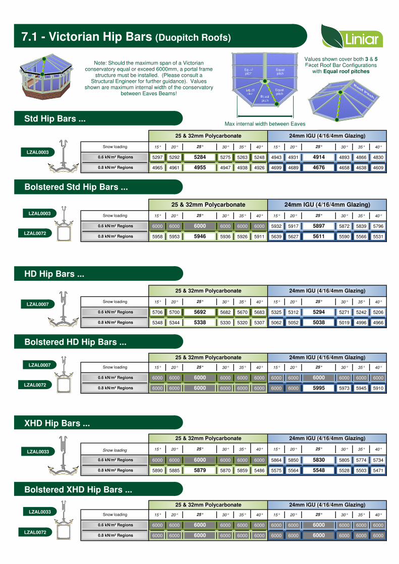
Std Hip Bars ...
Note: Should the maximum span of a Victorian conservatory equal or exceed 6000mm, a portal frame
structure must be installed. (Please consult a Structural Engineer for further guidance). Values
shown are maximum internal width of the conservatorybetween Eaves Beams!
Bolstered Std Hip Bars ...
HD Hip Bars ...
Bolstered HD Hip Bars ...
Bolstered XHD Hip Bars ...
XHD Hip Bars ...
7.1 - Victorian Hip Bars (Duopitch Roofs)
LZAL0033
LZAL0072
LZAL0007
LZAL0072
LZAL0003
LZAL0072
LZAL0033
LZAL0007
LZAL0003
Values shown cover both 3 & 5Facet Roof Bar Configurations
with Equal roof pitches
Max internal width between Eaves
Equalpitch
Equalpitch
Equalpitch
Equalpitch
Equalpitch

15° 3978 4146 3500 3656 3745 3904 3311 3459 3544 3694 3146 3287 3368 3511
20° 3906 4069 3445 3594 3681 3835 3261 3403 3485 3631 3100 3237 3314 3454
25° 3836 3995 3391 3534 3617 3767 3212 3348 3428 3570 3055 3186 3262 3398
30° 3766 3921 3337 3473 3554 3700 3163 3293 3370 3509 3010 3135 3209 3342
35° 3696 3846 3282 3412 3490 3633 3113 3237 3312 3447 2964 3084 3155 3284
40° 3623 3770 3225 3348 3424 3563 3060 3179 3251 3383 2916 3030 3099 3225
15° 4483 4698 4163 4223 4426 3942 3998 4192 3748 3802 3986
20° 4386 4592 4077 4135 4331 3864 3919 4105 3677 3729 3907
25° 4292 4489 3994 4051 4238 3788 3841 4020 3607 3658 3829
30° 4200 4389 3912 3967 4147 3713 3765 3937 3538 3588 3753
35° 4107 4289 3829 3883 4056 3637 3688 3853 3468 3517 3675
40° 4012 4186 3743 3797 3962 3558 3609 3767 3395 3443 3595
15° 3647 3803 3203 3348 3431 3578 3028 3165 3243 3383 2875 3006 3081 3213
20° 3597 3750 3163 3305 3386 3530 2994 3127 3204 3340 2844 2971 3044 3174
25° 3547 3697 3128 3263 3341 3482 2960 3088 3163 3297 2813 2936 3007 3135
30° 3497 3643 3090 3219 3296 3434 2925 3049 3122 3253 2872 2900 2970 3095
35° 3444 3588 3050 3174 3249 3384 2889 3008 3079 3208 2749 2863 2930 3053
40° 3389 3530 3008 3127 3199 3332 2851 2965 3034 3160 2713 2823 2889 3009
15° 4119 4320 3821 3876 4066 3615 3667 3848 3435 3485 3656
20° 4049 4243 3760 3814 3998 3560 3611 3785 3384 3433 3600
25° 3980 4167 3699 3752 3930 3504 3555 3724 3334 3382 3543
30° 3911 4092 3637 3690 3861 3448 3498 3662 3283 3330 3486
35° 3840 4014 3574 3626 3791 3391 3440 3598 3230 3277 3428
40° 3766 3934 3508 3559 3719 3331 3379 3531 3174 3220 3366
Up to 22m/s Up to 24m/s Up to 26m/s
≤0.1km 2km≤0.1km 2km 10km ≥ 100km ≤0.1km 2km 10km ≥ 100km
Sit
e i
n C
ou
ntr
y
Roof P
itches u
p to
Sit
e i
n T
ow
n
Roof P
itches u
p to
Up to 20m/sSite Basic Wind Speed
Terrain
Co
nd
itio
ns
Closest distance to sea 10km ≥ 100km≤0.1km 2km
Site Basic Wind Speed Up to 20m/s Up to 22m/s Up to 24m/s Up to 26m/s
Terrain
Co
nd
itio
ns
Sit
e i
n C
ou
ntr
y
Roof P
itches u
p to
Sit
e i
n T
ow
n
Roof P
itches u
p to
Closest distance to sea 10km ≥ 100km
10km ≥ 100km
≤0.1km 2km 10km ≥ 100km ≤0.1km 2km 10km ≥ 100km ≤0.1km 2km 10km ≥ 100km ≤0.1km 2km
8.1 - Gable End (Duopitch Roofs)
Unreinforcend Eaves WITH Dwarf Walls ...None Reinforced Eaves WITH Dwarf Walls ...
None Reinforced Eaves WITHOUT Dwarf Walls ...
Width
LZAL0070
LZAL0070
Span conditions: Multiple support conditions provided with the window frame structure(provided by client)
Based upon the following assumptions:Height to Eaves = 2100mm, Height of dwarf wall = 600mm, Eaves = LZAL0070
Span conditions: Multiple support conditions provided with the window frame structure (provided by client)
Based upon the following assumptions:Height to Eaves = 2100mm, Height of dwarf wall = 0mm (N/A), Eaves = LZAL0070
Installations with continuous Gable (support) Eaves Beams,read in conjunction with Section 2.1 for Environmental Loadings
Note: Recommendations shown are for maximum conservatory width, irrespective of the glazing material element being installed.

15° 5259 5479 4638 4839 4955 5163 4390 4582 4692 4889 4174 4357 4462 4650
20° 5142 5354 4547 4738 4849 5050 4308 4490 4596 4787 4099 4272 4374 4556
25° 5029 5235 4460 4640 4747 4942 4229 4401 4503 4688 4026 4191 4289 4465
30° 4919 5119 4374 4545 4648 4837 4150 4313 4412 4592 3953 4110 4204 4376
35° 4810 5004 4288 4449 4548 4732 4071 4226 4320 4495 3880 4029 4120 4287
40° 4699 4887 4200 4351 4446 4625 3990 4136 4226 4396 3805 3946 4033 4195
15° 5906 >6000 5491 5569 5832 5203 5277 5527 4951 5021 5260
20° 5749 >6000 5351 5427 5676 5076 5148 5386 4834 4903 5131
25° 5600 5851 5218 5292 5530 4954 5025 5252 4722 4789 5007
30° 5457 5695 5089 5162 5388 4836 4905 5122 4613 4679 4887
35° 5315 5542 4962 5032 5248 4718 4783 4993 4504 4568 4767
40° 5172 5388 4832 4901 5009 4599 4664 4862 4393 4456 4646
15° 4842 5047 4260 4449 4558 4751 4030 4209 4312 4496 3828 3999 4098 4272
20° 4758 4958 4197 4377 4483 4672 3973 4144 4244 4424 3776 3940 4036 4206
25° 4676 4872 4135 4307 4409 4593 3917 4080 4177 4352 3725 3882 3974 4141
30° 4594 4785 4073 4236 4335 4515 3860 4016 4110 4281 3673 3823 3913 4076
35° 4511 4697 4009 4164 4259 4435 3801 3950 4041 4208 3619 3765 3849 4009
40° 4424 4606 3942 4089 4181 4352 3740 3881 3969 4132 3563 3699 3783 3939
15° 5451 5712 5062 5135 5382 4792 4861 5096 4556 4622 4846
20° 5336 5586 4959 5031 5268 4699 4767 4993 4471 4536 4751
25° 5224 5463 4860 4930 5157 4609 4675 4892 4389 4452 4659
30° 5113 5342 4761 4830 5048 4519 4584 4792 4306 4368 4567
35° 5001 5221 4661 4728 4938 4427 4491 4691 4221 4282 4474
40° 4887 5097 4558 4624 4824 4332 4395 4587 4134 4194 4378
Site Basic Wind Speed Up to 20m/s Up to 22m/s Up to 24m/s Up to 26m/s
10kmClosest distance to sea ≤0.1km 2km 10km ≥ 100km ≤0.1km 2km 10km ≥ 100km ≤0.1km 2km
Terrain
Co
nd
itio
ns
Sit
e i
n C
ou
ntr
y
Roof P
itches u
p to
Sit
e i
n T
ow
n
Roof P
itches u
p to
≥ 100km ≤0.1km 2km 10km ≥ 100km
Site Basic Wind Speed Up to 20m/s Up to 22m/s Up to 24m/s Up to 26m/s
Closest distance to sea ≤0.1km 2km 10km ≥ 100km 10km≤0.1km 2km 10km ≥ 100km ≤0.1km 2km ≥ 100km ≤0.1km 2km 10km ≥ 100km
Terrain
Co
nd
itio
ns
Sit
e i
n C
ou
ntr
y
Roof P
itches u
p to
Sit
e i
n T
ow
n
Roof P
itches u
p to
Unreinforcend Eaves WITH Dwarf Walls ...Reinforced Eaves WITH Dwarf Walls ...
Reinforced Eaves WITHOUT Dwarf Walls ...
Width
LZAL0070+LZAL0071
Installations with continuous Gable (support) Eaves Beams,read in conjunction with Section 2.1 for Environmental Loadings
Note: Recommendations shown are for maximum conservatory width, irrespective of the glazing material element being installed.
LZAL0070+LZAL0071
Span conditions: Multiple support conditions provided with the window frame structure(provided by client)
Based upon the following assumptions:Height to Eaves = 2100mm, Height of dwarf wall = 600mm, Eaves = LZAL0070 + LZAL0071 (Steel Rein)
Span conditions: Multiple support conditions provided with the window frame structure (provided
Based upon the following assumptions:Height to Eaves = 2100mm, Height of dwarf wall = 0mm (N/A), Eaves = LZAL0070 + LZA0071 (Steel Rein)
8.2 - Gable Ends (Duopitch Roofs)

Max length of valley = Angle of valley in plan view =
Length = √ ( Span² + Projection² ) Tan c° = ( Span / Projection )
or Length = ( Span / sin c° )
or Length = ( Projection / cos c° )
15° 20° 25° 30° 35° 40°
45.00 63.61 71.92 33.35 79.37 81.38 82.88
Span (1/2 width of roof a) = 26.39 45.00 56.65 64.15 69.29 73.02 75.85
Span = √ ( Length² - Projection² ) 15° 18.08 33.35 45.00 53.64 60.12 65.10 69.06
or Span = ( Length * sin c° ) 20° 13.52 25.85 36.36 45.00 52.03 57.77 62.53
or Span = ( Projection * tan c° ) 25° 10.63 20.71 29.88 37.97 45.00 51.07 56.34
30° 8.62 16.98 24.90 32.23 38.93 45.00 50.49
35° 7.12 14.15 20.94 27.47 33.66 39.51 45.00
40°
Projection (roof b) =
Projection = √ ( Length² - Span² )
or Projection = ( Length * cos c° )
or Projection = ( Span / tan c° )
Minimum roof pitch for Duopitch = 15°
Minimum roof pitch for Monopitch = 5°
Maximum roof pitch (a & b) = 35°
5° 10°Angle ' c '
Roof pitch 'b
' (fo
r D
uopitch's
)
Roof pitch 'b
' (fo
r M
onopitch's
)
Roof pitch ' a ' (for Duopitch roofs)
Roof pitch ' a ' (for Monopitch roofs)
10°
5°
9.1 - Valley (Combined Roofs) ...
Note: Should the maximum span of the conservatory equal or exceed 6000mm (5200mm for georgian in glass), a portal frame structure must be installed (Please consult a Structural Engineer for further guidance). Values shown are maximum distances the valley can span in PLAN, they are NOT the length of the valley!
Max length of valley (L) = √ (S²+P²)
Span (S) = 1/2 Width of roof 'a'
Length (L)
Width of roof 'a'
Projection (P) =Projection of roof 'b'c° Roof pitch 'a' Roof pitch 'b'
Valley Length in plan ... Angle c in plan ...
Span (roof a) ...
Projection (roof b) ...
Projection (P)
Span (S)

5° 10° 15° 20° 25° 30° 35° 40° 5° 10° 15° 20° 25° 30° 35° 40°
5° 3795 4014 4058 4090 4110 4126 4136 3719 3762 3810 3841 3859 3867 3867
10° 4014 3961 3970 3990 4011 4031 4045 3762 3704 3713 3733 3751 3764 3769
15° 4058 3970 3937 3931 3938 3948 3960 3810 3713 3681 3674 3677 3683 3686
20° 4090 3990 3931 3900 3885 3881 3883 3841 3733 3674 3646 3628 3619 3612
25° 4110 4011 3938 3885 3851 3828 3792 3859 3751 3677 3628 3599 3573 2893
30° 4126 4031 3948 3881 3828 3788 3756 3867 3764 3683 3619 3573 3540 3502
35° 4136 4045 3960 3883 3792 3756 3708 3867 3769 3686 3612 2893 3502 3465
40°
5° 3730 3773 3826 3864 3890 3939 3911 3537 3578 3624 3656 3674 3685 3687
10° 3773 3718 3729 3755 3782 3806 3825 3578 3524 3532 3553 3572 3587 3595
15° 3826 3729 3697 3695 3707 3722 3740 3624 3532 3503 3497 3502 3508 3515
20° 3864 3755 3695 3668 3658 3659 3665 3656 3553 3497 3470 3445 3449 3445
25° 3890 3782 3707 3658 3629 3611 3604 3674 3572 3502 3445 3428 3404 3387
30° 3939 3806 3722 3659 3611 3578 3554 3685 3587 3508 3449 3404 3373 3341
35° 3911 3825 3740 3665 3604 3554 3514 3687 3595 3515 3445 3387 3341 3304
40°
1.6
24mm IGU (4/16/4mm Glazing)Roof Pitch a Roof Pitch a
Roof P
itch b
En
vir
on
men
tal S
no
w L
oad
ing
0.6
kN
/m²
Reg
ion
s
Roof P
itch b
0.8
kN
/m²
Reg
ion
s
25 & 32mm Polycarbonate
Valley ...
Note: Values shown are maximum distance thevalley can span in PLAN, they are NOT the
length of the valley wings!
9.2 - Valley (Combined Roofs) ...
Span (S)
Pro
jectio
n (
P)
Max length of valley(L) = √ (S²+P²)
The max pitch for roof a & b is 35°, any pitches shown in grey are beyond acceptable perameters
Additional guidlines …
Non-returnValley
If the style constitutes a non-return valley (Victorian facets) assembly, the design will be only made available in
POLYCARBONATE glazing and WILL NOT be supplied in GlassThe minimum length of the supporting eaves beam should
be no less than 350mm to enable the valley wings to be sited correctly.
Position the glazing bar a minimum of 90mm behind the D-Ring (Radius). The first Tie-Bar should be located at this position. All tie-bars and Transom/Jack Rafters must be in-line.
Any further tie-bars requirements along the Ridge should be applied in accordance with Section 10
Roof pitch 'a'
Roof pitch 'b'
Length (L)

25 & 32mm Polycarbonate 3250 3250
24mm IGU (4/16/4mm Glazing) 3000 3250
P rojection W idth
P rojection W idth
25 & 32mm Polycarbonate 3300 3250
24mm IGU (4/16/4mm Glazing) 3000 3250
25 & 32mm Polycarbonate
24mm IGU (4/16/4mm Glazing)
P rojection W idth
3250 3250
3500 3250
10.1 - Tie Bar Guidelines ...
Suitable lateral & vertical support must be provided within wall/window structure at the edgeof the opening by the conservatory designer/retailer to support the Eaves Beam
Liniar Roof's can not accept responsibility for the overall stability of the conservatory unless a portal frame is supplied
TIE BARS DO NOT OFFER ANY RESISTANCE TO LATERAL WIND LOADING
The conservatory is fixed to a host wall of suitable construction.
Standard eaves beams/box gutters are used at a common level & the roof is symmetrical.
The roof angle is between 25°- 40°or 15°- 40°when tie bars are required.
Structural openings up to 1.85m are required.
The first tie-bar is in line with the first glazing bar on the ridge behind the finial, if required. If more tie bars are required spacings tie bar/tie bar and tie bar/wall should be equal.
Standard tie bar to transom bar and corner connections are used.
Tie bars should be correctly installed before glazing material & never more than 2.4m from another tie bar or corner joint/wall.
Fabricated special box gutters are not included in the design of the conservatory, if required contact the Zoom Technical Department for tie bar positions and special box gutter reinforcement details.
See specific notes for different roof styles.
The snow load is less than 0.8kN/m2, see Snow Load Map in section 2.1
For additional information on structural stability please refer to the Glass & Glazing Federation's glazing manual data sheet 5.7.10.
Combined Roofs - max dim's before Tie-Bars are required ...
Width
Pro
jectio
n
Gable's ...
Width
Pro
jectio
n
Edwardian's ...
Width
Pro
jectio
n
Victorian's ...
Tie-Bars are required in these basic designs when the dimensions illustrated (in mm's) are exceeded.
Most combination roofs will require Tie-Bars
Tie-Bar info provided with this guide is for Liniar roofs where...
Refer to section 10.4
Refer to section 10.6
Refer to section 10.2

1 1 1 1 1 1 1 1 1 1
1 1 1 1 1 1 1 1 1 1
1 1 1 1 1 1 1 1 1 1
1 1 1 1 1 1 1 1 1 1 1 1 1 1 1
1 1 1 1 1 1 1 1 1 1 1 1 1 1 1
1 1 1 1 1 1 1 1 1 1 1 1 1 1 1 1 1 1 1 1 1 1
1 1 1 1 1 1 1 1 1 1 1 1 1 1 1 1 1 1 1 1 1 1
1 1 1 1 1 1 1 1 1 1 1 1 1 1 1 1 1 1 1 1 1 1
1 1 1 1 1 1 1 1 1 1 1 1 1 1 1 1 1 1 1 1 1 1
1 1 1 1 1 1 1 1 1 1 1 1 1 2 1 1 1 1 1 1 1 1
2 1 1 1 1 1 1 1 2 2 2 2 2 2 2 1 1 1 1 1 1 2
2 2 2 1 1 1 1 2 2 2 2 2 2 2 2 2 1 1 1 1 2 2
2 2 2 2 2 2 2 2 2 2 2 2 2 2 2 2 2 2 2 2 2 2
1 1 1 1 1 1 1 1 1 1 1 1 1 1 1 1 1 1 1 1 1 1
1 1 1 1 1 1 1 1 1 1 1 1 1 1 1 1 1 1 1 1 1 1
1 1 1 1 1 1 1 1 1 1 1 1 1 1 1 1 1 1 1 1 1 1
1 1 1 1 1 1 1 1 1 1 1 1 1 1 1 1 1 1 1 1 1 1
1 1 1 1 1 1 1 1 1 1 1 1 1 1 1 1 1 1 1 1 1 1
1 1 1 1 1 1 1 1 1 1 1 1 1 1 1 1 1 1 1 1 1 1
1 1 1 1 1 1 1 1 1 1 1 1 1 1 1 1 1 1 1 1 1 1
1 1 1 1 1 1 1 1 1 1 1 1 1 1 1 1 1 1 1 1 1 1
1 1 1 1 1 1 1 1 1 1 1 1 1 1 1 1 1 1 1 1 1 1
1 1 1 1 1 1 1 1 1 1 1 1 1 2 1 1 1 1 1 1 1 1
2 1 1 1 1 1 1 1 2 2 2 2 2 2 2 1 1 1 1 1 1 2
2 2 2 1 1 1 1 2 2 2 2 2 2 2 2 2 1 1 1 1 2 2
2 2 2 2 2 2 2 2 2 2 2 2 2 2 2 2 2 2 2 2 2 2
5750
25 & 32mm Polycarbonate 24mm IGU (4/16/4mm Glazing)
Internal Roof W idth (mm) Internal Roof W idth (mm)
3000 3250 3500 3750 4000 4250 4500 4750 5000 5250 5500 55006000 3000 3250 3500 3750 4000
5750
5750 6000
Inte
rna
l R
oo
f P
roje
ctio
n (
mm
)
3000
Re
qu
ire
me
nts
ex
ce
ed
Lin
iar
Ro
o's
rec
om
me
nd
ati
on
fo
r g
las
s, a
PO
RT
AL
FR
AM
E S
ys
tem
mu
st
be
in
sta
lle
d
3250
3500
3750
4000
4250
4250 4500 4750 5000 5250
4500
4750
5000
5250
5500
3000 3250 3500 3750 4000
6000
25 & 32mm Polycarbonate 24mm IGU (4/16/4mm Glazing)
Internal Roof W idth (mm) Internal Roof W idth (mm)
37504250 4500 4750 5000 5250 5500 5750 6000 3000 3250 3500 5500 5750 6000
Inte
rna
l R
oo
f P
roje
ctio
n (
mm
)
3000
Re
qu
ire
me
nts
ex
ce
ed
Lin
iar
Ro
o's
rec
om
me
nd
ati
on
fo
r g
las
s, a
PO
RT
AL
FR
AM
E S
ys
tem
mu
st
be
in
sta
lle
d
3250
3500
3750
4000
4000 4250 4500 4750 5000 5250
5750
6000
4250
4500
4750
5000
5250
5500
10.2 - Tie Bars (Edwardian Roofs)
Width Projection
Edwardian Roof pitches 25°or greater ...
Suitable lateral & vertical support must be provided within wall/window structure at the edgeof the opening by the conservatory designer/retailer to support the Eaves Beam
Liniar Roof's can not accept responsibility for the overall stability of the conservatory unless a portal frame is supplied
TIE BARS DO NOT OFFER ANY RESISTANCE TO LATERAL WIND LOADING
The tables below detail the minimum Tie-Bar requirements based on the width, projection and roof pitch. It is necessary to apply a Tie bar for all Edwardian roofs below the default 25°pitch. recommendations assume the standard eaves beams/box gutters are used at a common level & the roof is symmetrical. The first tie-bar is in line with the first glazing bar on the ridge behind the finial, if required. If more tie bars are required spacings tie bar/tie bar and tie bar/wall should be equal. Structural openings up to 1.85m are required. Tie bars should be correctly installed before glazing material and never more than 2.4m from another tie bar or corner joint/wall.
Recommendations for snow loading regions less than 0.8kN/m², please contact Liniar Roof's Technical Department for further guidance
Edwardian Roof pitches less than 25°...
1 1 1 1 1 1 1 1 1 1 1 1 1 1
1 1 1 1 1 1 1 1 1 1 1 1 1 1
1 1 1 1 1 1 1 1 1 1 1 1 1
1 1 1 1 1 1 1 1 1 1 1 1 1 1
1 1 1 1 1 1 1 1 1 1 1 1 1
1 1 1 1 1 1 1 1 1 1 1 1 1 1 1 1
1 1 1 1 1 1 1 1 1 1 1 1 1 1 1 1
1 1 1 1 1 1 1 1 1 1 1 1 1 1 1 1
1 1 1 1 1 1 1 1 1 1 1 1 1 1 1 1 1
1 1 1 1 1 1 1 1 1 1 1 1 1 1 1 1 1 1
1 1 1 1 1 1 1 1 1 1 1 1 1 1 1 1 1 1 1
1 1 1 1 1 1 1 1 1 1 1 1 1 1 1 1 1 1 1
1 1 1 1 1 1 1 1 1 1 1 1 1 1 1 1 1 1 1 1
1 1 1 1 1 1 1 1 1 1 1 1 1 1 1 1 1 1 1 1 1 1
1 1 1 1 1 1 1 1 1 1 1 1 1 1 1 1 1 1 1 1 1 1
1 1 1 1 1 1 1 1 1 1 1 1 1 1 1 1 1 1 1 1 1 1
1 1 1 1 1 1 1 1 1 1 1 1 1 1 1 1 1 1 1 1 1 1
1 1 1 1 1 1 1 1 1 1 1 1 1 1 1 1 1 1 1 1 1 1
1 1 1 1 1 1 1 1 1 1 1 1 1 1 1 1 1 1 1 1 1 1
1 1 1 1 1 1 1 1 1 1 1 1 1 1 1 1 1 1 1 1 1 1
1 1 1 1 1 1 1 1 1 1 1 1 1 1 1 1 1 1 1 1 1 1
1 1 1 1 1 1 1 1 1 1 1 1 1 1 1 1 1 1 1 1 1 1
1 1 1 1 1 1 1 1 1 1 1 1 1 1 1 1 1 1 1 1 1 1
1 1 1 1 1 1 1 1 1 1 1 1 1 1 1 1 1 1 1 1 1 1
1 1 1 1 1 1 1 1 1 1 1 1 1 1 1 1 1 1 1 1 1 1
1 1 1 1 1 1 1 1 1 1 1 1 1 1 1 1 1 1 1 1 1 1
5750
25 & 32mm Polycarbonate 24mm IGU (4/16/4mm Glazing)
Internal Roof W idth (mm) Internal Roof W idth (mm)
3000 3250 3500 3750 4000 4250 4500 4750 5000 5250 5500 55006000 3000 3250 3500 3750 4000
5750
5750 6000
Inte
rna
l R
oo
f P
roje
ctio
n (
mm
)
3000
Re
qu
ire
me
nts
ex
ce
ed
Lin
iar
Ro
o's
rec
om
me
nd
ati
on
fo
r g
las
s, a
PO
RT
AL
FR
AM
E S
ys
tem
mu
st
be
in
sta
lle
d
3250
3500
3750
4000
4250
4250 4500 4750 5000 5250
4500
4750
5000
5250
5500
3000 3250 3500 3750 4000
6000
25 & 32mm Polycarbonate 24mm IGU (4/16/4mm Glazing)
Internal Roof W idth (mm) Internal Roof W idth (mm)
37504250 4500 4750 5000 5250 5500 5750 6000 3000 3250 3500 5500 5750 6000
Inte
rna
l R
oo
f P
roje
ctio
n (
mm
)
3000
Re
qu
ire
me
nts
ex
ce
ed
Lin
iar
Ro
o's
rec
om
me
nd
ati
on
fo
r g
las
s, a
PO
RT
AL
FR
AM
E S
ys
tem
mu
st
be
in
sta
lle
d
3250
3500
3750
4000
4000 4250 4500 4750 5000 5250
5750
6000
4250
4500
4750
5000
5250
5500
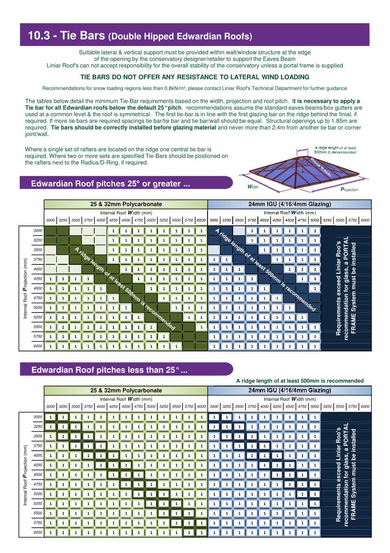
10.3 - Tie Bars (Double Hipped Edwardian Roofs)
WidthProjection
Edwardian Roof pitches 25°or greater ...
Suitable lateral & vertical support must be provided within wall/window structure at the edgeof the opening by the conservatory designer/retailer to support the Eaves Beam
Liniar Roof's can not accept responsibility for the overall stability of the conservatory unless a portal frame is supplied
TIE BARS DO NOT OFFER ANY RESISTANCE TO LATERAL WIND LOADING
The tables below detail the minimum Tie-Bar requirements based on the width, projection and roof pitch. It is necessary to apply a Tie bar for all Edwardian roofs below the default 25°pitch. recommendations assume the standard eaves beams/box gutters are used at a common level & the roof is symmetrical. The first tie-bar is in line with the first glazing bar on the ridge behind the finial, if required. If more tie bars are required spacings tie bar/tie bar and tie bar/wall should be equal. Structural openings up to 1.85m are required. Tie bars should be correctly installed before glazing material and never more than 2.4m from another tie bar or corner joint/wall.
Recommendations for snow loading regions less than 0.8kN/m², please contact Liniar Roof's Technical Department for further guidance
Edwardian Roof pitches less than 25°...A ridge length of at least 500mm is recommended
A ridge length of at least 500mm is recommended
Where a single set of rafters are located on the ridge one central tie bar is required. Where two or more sets are specified Tie-Bars should be postioned on the rafters next to the Radius/D-Ring, if required.
1 1 1 1 1 1 1 1 1
1 1 1 1 1 1 1 1 1 1 1 1 1
1 1 1 1 1 1 1 1 1 1 1 1 1 1 1 1 1 1 1 1 1
1 1 1 1 1 1 1 1 1 1 1 1 1 1 1 1 1 1 1 1 1
1 1 1 1 1 1 1 1 1 1 1 1 1 1 1 1 1 1 1 1 1 1 1 1 1 1
1 1 1 1 1 1 1 1 1 1 1 1 1 1 1 1 1 1 1 1 1 1 1 1 1 1
1 1 1 1 1 1 1 1 1 1 1 1 1 1 1 1 1 1 1 1 1 1 1 1 1 1
1 1 1 1 1 1 1 1 1 1 1 1 1 1 1 1 1 1 1 1 1 1 1 1 1 1
1 1 1 1 1 1 1 1 1 1 1 1 1 1 1 1 1 1 1 1 1 1 1 1 1 1
2 2 2 2 1 1 1 1 1 1 1 1 1 2 2 2 2 1 1 1 1 1 1 1 1 1
2 2 2 2 2 2 2 2 2 1 1 1 1 2 2 2 2 2 2 2 2 2 1 1 1 1
2 2 2 2 2 2 2 2 2 2 2 2 2 2 2 2 2 2 2 2 2 2 2 2 2 2
1 1 1 1 1 1 1 1 1 1 1 1 1 1 1 1 1 1 1 1 1 1 1 1 1 1
1 1 1 1 1 1 1 1 1 1 1 1 1 1 1 1 1 1 1 1 1 1 1 1 1 1
1 1 1 1 1 1 1 1 1 1 1 1 1 1 1 1 1 1 1 1 1 1 1 1 1 1
1 1 1 1 1 1 1 1 1 1 1 1 1 1 1 1 1 1 1 1 1 1 1 1 1 1
1 1 1 1 1 1 1 1 1 1 1 1 1 1 1 1 1 1 1 1 1 1 1 1 1 1
1 1 1 1 1 1 1 1 1 1 1 1 1 1 1 1 1 1 1 1 1 1 1 1 1 1
1 1 1 1 1 1 1 1 1 1 1 1 1 1 1 1 1 1 1 1 1 1 1 1 1 1
1 1 1 1 1 1 1 1 1 1 1 1 1 1 1 1 1 1 1 1 1 1 1 1 1 1
1 1 1 1 1 1 1 1 1 1 1 1 1 1 1 1 1 1 1 1 1 1 1 1 1 1
1 1 1 1 1 1 1 1 1 1 1 1 1 1 1 1 1 1 1 1 1 1 1 1 1 1
2 2 2 2 1 1 1 1 1 1 1 1 1 2 2 2 2 1 1 1 1 1 1 1 1 1
2 2 2 2 2 2 2 2 2 1 1 1 1 2 2 2 2 2 2 2 2 2 1 1 1 1
2 2 2 2 2 2 2 2 2 2 2 2 2 2 2 2 2 2 2 2 2 2 2 2 2 2
25 & 32mm Polycarbonate 24mm IGU (4/16/4mm Glazing)
Internal Roof W idth (mm) Internal Roof W idth (mm)
3000 3250 3500 3750 4000 4250 40004500 4750 5000 5250 5500
5750
5750 6000
Inte
rna
l R
oo
f P
roje
ctio
n (
mm
)
3000
3250
3500
3750
4000
4250
4250 4500 4750 5000 52505750 5500
4500
4750
5000
5250
37506000 3000 3250 3500
5500
5500
6000
25 & 32mm Polycarbonate 24mm IGU (4/16/4mm Glazing)
Internal Roof W idth (mm) Internal Roof W idth (mm)
3000 3250 3500 3750 4000 4250 4500 4750 5000 5250 6000 3000 3250 35005750 3750 5500 5750 6000
Inte
rna
l R
oo
f P
roje
ctio
n (
mm
)
3000
3250
3500
3750
4000
4000 4250 4500 4750 5000 5250
5750
6000
4250
4500
4750
5000
5250
5500
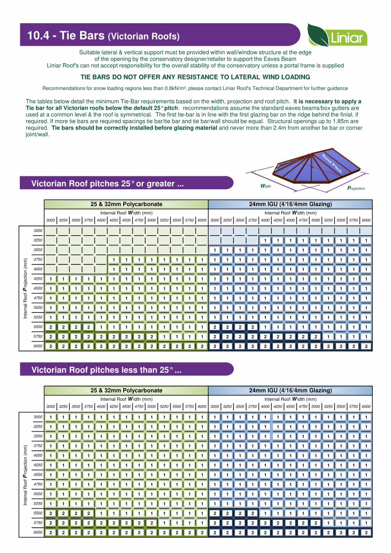
10.4 - Tie Bars (Victorian Roofs)
Victorian Roof pitches 25°or greater ...
Suitable lateral & vertical support must be provided within wall/window structure at the edgeof the opening by the conservatory designer/retailer to support the Eaves Beam
Liniar Roof's can not accept responsibility for the overall stability of the conservatory unless a portal frame is supplied
TIE BARS DO NOT OFFER ANY RESISTANCE TO LATERAL WIND LOADING
The tables below detail the minimum Tie-Bar requirements based on the width, projection and roof pitch. It is necessary to apply a Tie bar for all Victorian roofs below the default 25°pitch. recommendations assume the standard eaves beams/box gutters are used at a common level & the roof is symmetrical. The first tie-bar is in line with the first glazing bar on the ridge behind the finial, if required. If more tie bars are required spacings tie bar/tie bar and tie bar/wall should be equal. Structural openings up to 1.85m are required. Tie bars should be correctly installed before glazing material and never more than 2.4m from another tie bar or corner joint/wall.
Recommendations for snow loading regions less than 0.8kN/m², please contact Liniar Roof's Technical Department for further guidance
Victorian Roof pitches less than 25°...
WidthProjection

1 1 1 1 1 1 1 1 1 1 1 1
1 1 1 1 1 1 1 1 1 1 1 1
1 1 1 1 1 1 1 1 1 1 1 1
1 1 1 1 1 1 1 1 1 1 1
1 1 1 1 1 1 1 1 1 1 1 1 1
1 1 1 1 1 1 1 1 1 1 1 1
1 1 1 1 1 1 1 1 1 1 1 1 1 1 1 1
1 1 1 1 1 1 1 1 1 1 1 1 1 1 1 1
1 1 1 1 1 1 1 1 1 1 1 1 1 1 1 1 1
1 1 1 1 1 1 1 1 1 1 1 1 1 1 1 1 1 1
1 1 1 1 1 1 1 1 1 1 1 1 1 1 1 1 1 1 1
1 1 1 1 1 1 1 1 1 1 1 1 1 1 1 1 1 1 1
1 1 1 1 1 1 1 1 1 1 1 1 1 1 1 1 1 1 1 1
1 1 1 1 1 1 1 1 1 1 1 1 1 1 1 1 1 1 1 1 1 1
1 1 1 1 1 1 1 1 1 1 1 1 1 1 1 1 1 1 1 1 1 1
1 1 1 1 1 1 1 1 1 1 1 1 1 1 1 1 1 1 1 1 1 1
1 1 1 1 1 1 1 1 1 1 1 1 1 1 1 1 1 1 1 1 1 1
1 1 1 1 1 1 1 1 1 1 1 1 1 1 1 1 1 1 1 1 1 1
1 1 1 1 1 1 1 1 1 1 1 1 1 1 1 1 1 1 1 1 1 1
1 1 1 1 1 1 1 1 1 1 1 1 1 1 1 1 1 1 1 1 1 1
1 1 1 1 1 1 1 1 1 1 1 1 1 1 1 1 1 1 1 1 1 1
1 1 1 1 1 1 1 1 1 1 1 1 1 1 1 1 1 1 1 1 1 1
1 1 1 1 1 1 1 1 1 1 1 1 1 1 1 1 1 1 1 1 1 1
1 1 1 1 1 1 1 1 1 1 1 1 1 1 1 1 1 1 1 1 1 1
1 1 1 1 1 1 1 1 1 1 1 1 1 1 1 1 1 1 1 1 1 1
1 1 1 1 1 1 1 1 1 1 1 1 1 1 1 1 1 1 1 1 1 1
5750
25 & 32mm Polycarbonate 24mm IGU (4/16/4mm Glazing)
Internal Roof W idth (mm) Internal Roof W idth (mm)
3000 3250 3500 3750 4000 4250 4500 4750 5000 5250 5500 55006000 3000 3250 3500 3750 4000
5750
5750 6000
Inte
rna
l R
oo
f P
roje
ctio
n (
mm
)
3000
Re
qu
ire
me
nts
ex
ce
ed
Lin
iar
Ro
o's
rec
om
me
nd
ati
on
fo
r g
las
s, a
PO
RT
AL
FR
AM
E S
ys
tem
mu
st
be
in
sta
lle
d
3250
3500
3750
4000
4250
4250 4500 4750 5000 5250
4500
4750
5000
5250
5500
3000 3250 3500 3750 4000
6000
25 & 32mm Polycarbonate 24mm IGU (4/16/4mm Glazing)
Internal Roof W idth (mm) Internal Roof W idth (mm)
37504250 4500 4750 5000 5250 5500 5750 6000 3000 3250 3500 5500 5750 6000
Inte
rna
l R
oo
f P
roje
ctio
n (
mm
)
3000
Re
qu
ire
me
nts
ex
ce
ed
Lin
iar
Ro
o's
rec
om
me
nd
ati
on
fo
r g
las
s, a
PO
RT
AL
FR
AM
E S
ys
tem
mu
st
be
in
sta
lle
d
3250
3500
3750
4000
4000 4250 4500 4750 5000 5250
5750
6000
4250
4500
4750
5000
5250
5500
10.5 - Tie Bars (Hipped back Victorian Roofs)
Hipped Victorian Roof pitches 25°or
greater...
Suitable lateral & vertical support must be provided within wall/window structure at the edgeof the opening by the conservatory designer/retailer to support the Eaves Beam
Liniar Roof's can not accept responsibility for the overall stability of the conservatory unless a portal frame is supplied
TIE BARS DO NOT OFFER ANY RESISTANCE TO LATERAL WIND LOADING
The tables below detail the minimum Tie-Bar requirements based on the width, projection and roof pitch. It is necessary to apply a Tie bar for all Edwardian roofs below the default 25°pitch. recommendations assume the standard eaves beams/box gutters are used at a common level & the roof is symmetrical. The first tie-bar is in line with the first glazing bar on the ridge behind the finial, if required. If more tie bars are required spacings tie bar/tie bar and tie bar/wall should be equal. Structural openings up to 1.85m are required. Tie bars should be correctly installed before glazing material and never more than 2.4m from another tie bar or corner joint/wall.
Recommendations for snow loading regions less than 0.8kN/m², please contact Liniar Roof's Technical Department for further guidance
Hipped Victorian Roof pitches less than 25°
...A ridge length of at least 500mm is recommended
Where a single set of rafters are located on the ridge one central tie bar is required. Where two or more sets are specified Tie-Bars should be postioned on the rafters next to the Radius/D-Ring, if required.
Width Projection
A ridge length of at least 500mm is recommended

1 1 1 1 1 1 1 1 1 1 1 1 1 1 1 1 1 1 1 1 1 1 1 1
1 1 1 1 1 1 1 1 1 1 1 1 1 1 1 1 1 1 1 1 1 1 1 1
1 1 1 1 1 1 1 1 1 1 1 2 2 1 1 1 1 2 2 2 2 2 2 2
1 1 2 2 2 2 2 2 2 2 2 2 2 2 2 2 2 2 2 2 2 2 2 2
2 2 2 2 2 2 2 2 2 2 2 2 2 2 2 2 2 2 2 2 2 2 2 2
2 2 2 2 2 2 2 2 2 2 2 2 2 2 2 2 2 2 2 2 2 2 2 2
2 2 2 2 2 2 2 2 2 2 2 2 2 2 2 2 2 2 2 2 2 2 2 2
2 2 2 2 2 2 2 2 2 2 2 2 2 2 2 2 2 2 2 2 2 2 2 2
2 2 2 2 2 2 2 2 2 2 2 2 2 2 2 2 2 2 2 2 2 2 2 2
2 2 2 2 2 2 2 2 2 2 2 2 2 2 2 2 2 2 2 2 2 2 2 2
2 2 2 2 2 2 2 2 2 2 2 2 2 2 2 2 2 2 2 2 2 2 2 2
2 2 2 2 2 2 2 2 2 2 2 2 2 2 2 2 2 2 2 2 2 2 2 2
2 2 2 2 2 2 2 2 2 2 2 2 2 3 3 3 3 3 3 3 3 3 3 3
25 & 32mm Polycarbonate 24mm IGU (4/16/4mm Glazing)
Internal Roof W idth (mm) Internal Roof W idth (mm)
3000 3250 3500 3750 4000 4250 40004500 4750 5000 5250 5500 5750 6000 3000 3250 3500
Inte
rna
l R
oo
f P
roje
ctio
n (
mm
)
3000
3250
3500
3750
4000
4250
4500
5500
Co
nta
ct
the L
inia
r R
oo
f's T
ech
inic
al
Dep
art
men
t
4750
5000
5250
5500
5750
6000
3750 5750 60004250 4500 4750 5000 5250
10.6 - Tie Bars (Gable Fronted Roofs)
Gable Roof (all pitches) ...
Suitable lateral & vertical support must be provided within wall/window structure at the edgeof the opening by the conservatory designer/retailer to support the Eaves Beam
Liniar Roof's can not accept responsibility for the overall stability of the conservatory unless a portal frame is supplied
TIE BARS DO NOT OFFER ANY RESISTANCE TO LATERAL WIND LOADING
Recommendations for snow loading regions less than 0.8kN/m², please contact Liniar Roof's Technical Department for further guidance
Width Projection
It is necessary to apply a Tie bar for all Gable Fronted roofs regardless of roof pitch. Based upon the standard eaves beams/box gutters are used at a common level & the roof is symmetrical. The first tie-bar is in line with the first glazing bar on the ridge behind the gable end. This can be ignored if the gable support connected by others can tie the eaves beams together and replace the first tie-bar. Structural openings up to 1.85m are required. Tie bars should be correctly installed before glazing material and never more than 2.4m from another tie bar or corner joint/wall.
First tie-bar in-line with first glazing bar
Tie-bars should be never more than 2.4m from another tie-bar or
corner joint/wall

1000 1250 1500 1750 2000 2250 2500 2750 3000 3250 3500 3750 4000 4250 4500 4750 5000
2720 2590 2490 2410 2330 2270 2220 2170 2120 2080 2050 2010 1980 1960 1930 1900 1880
2550 2430 2330 2250 2180 2120 2070 2020 1980 1950 1910 1880 1850 1830 1800 1780 1750
1000 1250 1500 1750 2000 2250 2500 2750 3000 3250 3500 3750 4000 4250 4500 4750 5000
3610 3470 3350 3250 3160 3080 3020 2960 2900 2850 2810 2760 2720 2680 2650 2620 2590
3420 3270 3160 3060 2970 2900 2830 2770 2720 2670 2630 2590 2550 2510 2480 2450 2420
1000 1250 1500 1750 2000 2250 2500 2750 3000 3250 3500 3750 4000 4250 4500 4750 5000
3540 3370 3240 3130 3040 2950 2880 2820 2760 2710 2660 2620 2580 2540 2510 2480 2450
3310 3160 3030 2930 2840 2760 2690 2630 2580 2530 2490 2450 2410 2370 2340 2310 2280
1000 1250 1500 1750 2000 2250 2500 2750 3000 3250 3500 3750 4000 4250 4500 4750 5000
4700 4510 4360 4230 4110 4010 3920 3840 3770 3710 3640 3590 3540 3490 3450 3400 3360
4440 4260 4100 3980 3870 3770 3680 3610 3540 3470 3420 3360 3310 3270 3230 3190 3150
1000 1250 1500 1750 2000 2250 2500 2750 3000 3250 3500 3750 4000 4250 4500 4750 5000
2720 2590 2490 2410 2330 2270 2210 2160 2120 2080 2040 2010 1970 1950 1920 1900 1880
2530 2410 2320 2240 2170 2110 2060 2010 1970 1940 1900 1870 1840 1810 1790 1770 1740
1000 1250 1500 1750 2000 2250 2500 2750 3000 3250 3500 3750 4000 4250 4500 4750 5000
3600 3460 3350 3240 3160 3080 3010 2950 2890 2840 2800 2750 2710 2680 2640 2610 2580
3400 3260 3140 3040 2960 2880 2820 2760 2710 2660 2610 2570 2530 2500 2470 2440 2410
1000 1250 1500 1750 2000 2250 2500 2750 3000 3250 3500 3750 4000 4250 4500 4750 5000
3530 3370 3240 3120 3030 2950 2880 2810 2760 2710 2660 2610 2570 2540 2500 2470 2440
3300 3140 3010 2910 2820 2750 2680 2620 2570 2520 2470 2430 2400 2360 2330 2300 2270
1000 1250 1500 1750 2000 2250 2500 2750 3000 3250 3500 3750 4000 4250 4500 4750 5000
4690 4500 4350 4220 4110 4010 3920 3840 3770 3700 3640 3580 3530 3480 3440 3400 3360
4420 4240 4090 3960 3850 3750 3670 3590 3520 3460 3420 3350 3300 3250 3210 3170 3130
(W) 25 & 32mm Poly
(W) 4/16/4mm Glazing
Projection of Roof (mm)
(W) 25 & 32mm Poly
(W) 4/16/4mm Glazing
Projection of Roof (mm)
Projection of Roof (mm)
(W) 25 & 32mm Poly
(W) 4/16/4mm Glazing
Projection of Roof (mm)
(W) 25 & 32mm Poly
(W) 4/16/4mm Glazing
(W) 25 & 32mm Poly
(W) 4/16/4mm Glazing
(W) 25 & 32mm Poly
(W) 4/16/4mm Glazing
(W) 4/16/4mm Glazing
Projection of Roof (mm)
Projection of Roof (mm)
(W) 25 & 32mm Poly
(W) 4/16/4mm Glazing
Projection of Roof (mm)
(W) 25 & 32mm Poly
11.1 - Unsupported Eaves Beam WidthsSuitable lateral & vertical support must be provided within wall/window structure at the edge of the opening by the conservatory designer/retailer to support the eaves beam
Values shown 5mm of deflection under maximum load must be confirmed as acceptable by the Bi-Fold door supplier (info related to bottom rolling doors)
LZAL0070
Monopitch Roofs - Full Openings ...
1/5th beyond support / start
LZAL0070+LZAL0071W
LZAL0070
Monopitch Roofs - Partial Openings ...
Projection
Width
LZAL0070+LZAL0071W
LZAL0070
Duopitch (Gable Ends) Roofs - Full Openings ...
Width
LZAL0070+LZAL0071W
Based upon the following assumptions: Imposed Load = 0.6 kN/m² with roof pitches up to 15°
Based upon the following assumptions: Imposed Load = 0.6 kN/m² with roof pitches up to 25°
Note: Eaves Beams in the Partial Opening must extend at least 1/5th beyond the support / start of the opening at both ends. The total length of Eaves Beam must therefore be at least 1.4 x Partial Opening1/5th beyond
support / start
LZAL0070
Duopitch (Gable Ends) Roofs - Partial Openings ...
Projection
Width
LZAL0070+LZAL0071W
Based upon the following assumptions: Imposed Load = 0.6 kN/m² with roof pitches up to 15°
Note: Eaves Beams in the Partial Opening must extend at least 1/5th beyond the support / start of the opening at both ends. The total length of Eaves Beam must therefore be at least 1.4 x Partial Opening
Based upon the following assumptions: Imposed Load = 0.6 kN/m² with roof pitches up to 15°
Projection
Projection
Width
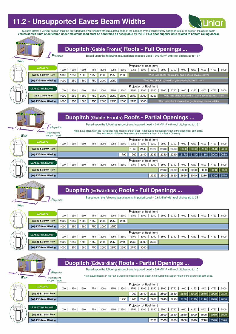
1000 1250 1500 1750 2000 2250 2500 2750 3000 3250 3500 3750 4000 4250 4500 4750 5000
1000 1250 1500 1750 2000 2250 2500
1000 1250 1500 1750 2000 2250
1000 1250 1500 1750 2000 2250 2500 2750 3000 3250 3500 3750 4000 4250 4500 4750 5000
1000 1250 1500 1750 2000 2250 2500 2750 3000 3250
1000 1250 1500 1750 2000 2250 2500 2750 3000
1000 1250 1500 1750 2000 2250 2500 2750 3000 3250 3500 3750 4000 4250 4500 4750 5000
1960 2140 2320 2500 2680 2860 3000 2960 2920 2890
1790 1960 2140 2280 2240 2210 2170 2140 2110 2090 2060
1000 1250 1500 1750 2000 2250 2500 2750 3000 3250 3500 3750 4000 4250 4500 4750 5000
2500 2680 2860 3000 3090 3050 3020
2320 2500 2680 2860 3040 3210 3390 3570
1000 1250 1500 1750 2000 2250 2500 2750 3000 3250 3500 3750 4000 4250 4500 4750 5000
1000 1250 1500 1750 2000 2250 2500
1000 1250 1500 1750 2000 2250
1000 1250 1500 1750 2000 2250 2500 2750 3000 3250 3500 3750 4000 4250 4500 4750 5000
1000 1250 1500 1750 2000 2250 2500 2750 3000 3250
1000 1250 1500 1750 2000 2250 2500 2750 3000
1000 1250 1500 1750 2000 2250 2500 2750 3000 3250 3500 3750 4000 4250 4500 4750 5000
1960 2140 2320 2500 2680 2860 3000 2960 2920 2890
1790 1960 2140 2280 2240 2210 2170 2140 2110 2090 2060
1000 1250 1500 1750 2000 2250 2500 2750 3000 3250 3500 3750 4000 4250 4500 4750 5000
2500 2680 2860 3000 3090 3050 3020
2320 2500 2680 2860 3040 3210 3390 3570(W) 4/16/4mm Glazing
Projection of Roof (mm)
(W) 25 & 32mm Poly
(W) 4/16/4mm Glazing
Projection of Roof (mm)
(W) 25 & 32mm Poly
(W) 4/16/4mm Glazing
Projection of Roof (mm)
(W) 25 & 32mm Poly
(W) 4/16/4mm Glazing
Projection of Roof (mm)
(W) 25 & 32mm Poly
(W) 4/16/4mm Glazing
Projection of Roof (mm)
(W) 25 & 32mm Poly
(W) 4/16/4mm Glazing
Projection of Roof (mm)
25 & 32mm Poly
(W) 4/16/4mm Glazing
Wind load check required for gable eaves beams > 3.9m
Wind load check required for gable eaves beams > 3.9m
Wind load check required for gable eaves beams > 4.5m
Wind load check required for gable eaves beams > 4.5m
Projection of Roof (mm)
(W) 25 & 32mm Poly
(W) 4/16/4mm Glazing
Projection of Roof (mm)
(W) 25 & 32mm Poly
Note: Eaves Beams in the Partial Opening must extend at least 1/5th beyond the support / start of the opening at both ends. The total length of Eaves Beam must therefore be at least 1.4 x Partial Opening
Based upon the following assumptions: Imposed Load = 0.6 kN/m² with roof pitches up to 15°
Suitable lateral & vertical support must be provided within wall/window structure at the edge of the opening by the conservatory designer/retailer to support the eaves beam
Values shown 5mm of deflection under maximum load must be confirmed as acceptable by the Bi-Fold door supplier (info related to bottom rolling doors)
LZAL0070
Duopitch (Gable Fronts) Roofs - Full Openings ...Projection
1/5th beyond support / start
Width
LZAL0070+LZAL0071W
LZAL0070
Duopitch (Gable Fronts) Roofs - Partial Openings ...
Projection
Width
LZAL0070+LZAL0071W
LZAL0070
Duopitch (Edwardian) Roofs - Full Openings ...
LZAL0070+LZAL0071W
Based upon the following assumptions: Imposed Load = 0.6 kN/m² with roof pitches up to 15°
Based upon the following assumptions: Imposed Load = 0.6 kN/m² with roof pitches up to 25°
Note: Eaves Beams in the Partial Opening must extend at least 1/5th beyond the support / start of the opening at both ends.
LZAL0070
Duopitch (Edwardian) Roofs - Partial Openings ...
LZAL0070+LZAL0071W
Based upon the following assumptions: Imposed Load = 0.6 kN/m² with roof pitches up to 15°
11.2 - Unsupported Eaves Beam Widths
Projection
Width
1/5th beyond support / start
Projection
Width

N/A - The joint profile IS NOT suitable for load bearing situations at this length and above
Consult - The joint profile IS suitable for load bearing situations at this length and above, however please consult the Liniar Technical Department prior to fabrication
Axial Load
(Tonnes)
3.13
Length
(mm)
Axial Load
(Tonnes)
Length
(mm)
Axial Load
(Tonnes)
1400 2.17 1800 1.49
1200 2.75 1600 2.41
2.98
3.03
3.08
1900
2000
2100
2200
Length
(mm)
Length
(mm)
1800
1700
1600
1500
Axial Load
(Tonnes)
3.44
3.37
3.29
1100 2.85 1500 2.50
3.55
3.50
Length
(mm)
1100
1200
1300
1400
Axial Load
(Tonnes)
3.67
3.61
3.21
1900 2.05
Length
(mm)
Axial Load
(Tonnes)
Length
(mm)
Axial Load
(Tonnes)
Length
(mm)
Axial Load
(Tonnes)
1400 2.60 1800 2.23 2200 Consult
2000 1.87
1300 2.68 1700 2.32 2100 1.67
1100 2.48 1500 2.07 1900 1.34
Length
(mm)
Axial Load
(Tonnes)
Length
(mm)
Axial Load
(Tonnes)
Length
(mm)
Axial Load
(Tonnes)
1300 2.3 1700 1.66 2100 1.13
1200 2.38 1600 1.87 2000 1.23
1100 2.47 1500 2.15 1900 1.63
2200 Consult
Length
(mm)
Axial Load
(Tonnes)
Length
(mm)
Axial Load
(Tonnes)
Length
(mm)
Axial Load
(Tonnes)
1300 2.33 1700 1.96 2100 1.34
1200 2.35 1600 2.06 2000 1.48
2.74 1900 2.43
1400 2.23 1800 1.80 2200 Consult
Key :
1400 2.81 1800 2.51 2200 Consult
1300 2.88 1700 2.59 2100 2.27
1200 2.98 1600 2.67 2000 2.35
Length
(mm)
Axial Load
(Tonnes)
1100 3.08 1500
12.1 - Structural Supports (Bay Poles) ...
LAN353 Pole Jack
90°Corner Posts ...
LAN253
LAN311 Pole Jack
135°Corner Posts ...
LAN251
LAN311 Pole Jack
150°Corner Posts ...
LAN252
LAN331 Pole Jack
Bespoke Angles ...
LAN231
LAN332 Pole Jack
LAN232
Edwardian, Gable & Lean-To
3-Facet Victorian
5-Facet Victorian
Small Bay Pole
Large Bay Pole
The following 'load tables' have been calculated in accordance with the relevant BPF Code of Practice,and are only applicable for joint profiles restrained at their centre
Liniar Roof's can not accept responsibility for the overall stability of the conservatory unless a portal frame is supplied
Suitable lateral & vertical support must be provided within wall/window structure at the edge of the openingby the conservatory designer/retailer to support the eaves beam
The load tables must not be applied to those joint profiles used in isolation
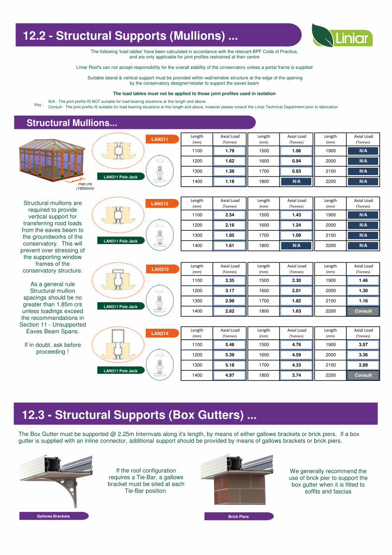
N/A - The joint profile IS NOT suitable for load bearing situations at this length and above
Consult - The joint profile IS suitable for load bearing situations at this length and above, however please consult the Liniar Technical Department prior to fabrication
1100 1.79 1500 1.06 1900 N/A
Length
(mm)
Axial Load
(Tonnes)
Length
(mm)
Axial Load
(Tonnes)
Length
(mm)
Axial Load
(Tonnes)
1300 1.38 1700 0.83 2100 N/A
1200 1.62 1600 0.94 2000 N/A
Length
(mm)
Axial Load
(Tonnes)
Length
(mm)
Axial Load
(Tonnes)
Length
(mm)
Axial Load
(Tonnes)
1400 1.18 1800 N/A 2200 N/A
1200 2.16 1600 1.24 2000 N/A
1100 2.54 1500 1.43 1900 N/A
1400 1.61 1800 N/A 2200 N/A
1300 1.85 1700 1.09 2100 N/A
1100 3.35 1500 2.30 1900 1.46
Length
(mm)
Axial Load
(Tonnes)
Length
(mm)
Axial Load
(Tonnes)
Length
(mm)
Axial Load
(Tonnes)
1300 2.98 1700 1.82 2100 1.16
1200 3.17 1600 2.01 2000 1.30
3.57
Length
(mm)
Axial Load
(Tonnes)
Length
(mm)
Axial Load
(Tonnes)
Length
(mm)
Axial Load
(Tonnes)
1400 2.62 1800 1.63 2200 Consult
Key :
1400 4.97 1800 3.74 2200 Consult
1300 5.18 1700 4.33 2100 2.89
1200 5.39 1600 4.59 2000 3.36
1100 5.48 1500 4.76 1900
LAN311 Pole Jack
Structural Mullions...
LAN211
The following 'load tables' have been calculated in accordance with the relevant BPF Code of Practice,and are only applicable for joint profiles restrained at their centre
Liniar Roof's can not accept responsibility for the overall stability of the conservatory unless a portal frame is supplied
Suitable lateral & vertical support must be provided within wall/window structure at the edge of the openingby the conservatory designer/retailer to support the eaves beam
The load tables must not be applied to those joint profiles used in isolation
LAN311 Pole Jack
LAN311 Pole Jack
LAN311 Pole Jack
LAN212
LAN213
LAN214
12.2 - Structural Supports (Mullions) ...
max crs(1850mm)
Structural mullions arerequired to provide vertical support for
transferring rood loads from the eaves beam to the groundworks of the conservatory. This will
prevent over stressing of the supporting window
frames of the conservatory structure.
As a general rule Structural mullion
spacings should be no greater than 1.85m crs unless loadings exceed the recommendations in
Section 11 - Unsupported Eaves Beam Spans.
If in doubt, ask before proceeding !
The Box Gutter must be supported @ 2.25m Internvals along it's length, by means of either gallows brackets or brick piers. If a box gutter is supplied with an inline connector, additional support should be provided by means of gallows brackets or brick piers.
Gallows Brackets
If the roof configuration requires a Tie-Bar, a gallows bracket must be sited at each
Tie-Bar position.
Brick Piers
We generally recommend the use of brick pier to support the box gutter when it is fitted to
soffits and fascias
12.3 - Structural Supports (Box Gutters) ...
