introducing vmware validated design for micro …...introducing vmware validated design for...
TRANSCRIPT
Introducing VMware Validated Designfor Micro-Segmentation
VMware Validated Design for Micro-Segmentation 3.0
This document supports the version of each product listed andsupports all subsequent versions until the document isreplaced by a new edition. To check for more recent editions ofthis document, see http://www.vmware.com/support/pubs.
EN-002235-00
Introducing VMware Validated Design for Micro-Segmentation
2 VMware, Inc.
You can find the most up-to-date technical documentation on the VMware Web site at:
http://www.vmware.com/support/
The VMware Web site also provides the latest product updates.
If you have comments about this documentation, submit your feedback to:
Copyright © 2016 VMware, Inc. All rights reserved. Copyright and trademark information.
VMware, Inc.3401 Hillview Ave.Palo Alto, CA 94304www.vmware.com
Contents
About Introducing VMware Validated Design for Micro-Segmentation 5
1 Overview of VMware Validated Designs 7
2 Use Case Overview and Design Objectives 9
VMware Validated Design for Micro-Segmentation Overview 9Micro-Segmentation Design Objectives 10
3 Documentation Structure and Audience 13
4 Components and Layers 17
VMware Software Components in the Validated Design for Micro-Segmentation 17Logical Design 18Physical Infrastructure Layer 20Virtual Infrastructure Layer 22
VMware, Inc. 3
Introducing VMware Validated Design for Micro-Segmentation
4 VMware, Inc.
About Introducing VMware Validated Design forMicro-Segmentation
Introducing VMware Validated Design for Micro-Segmentation explains how to use the VMware ValidatedDesign™ for Micro-Segmentation documents. This introduction also includes the design objectives and ahigh-level overview of design.
Introducing VMware Validated Design for Micro-Segmentation includes the following information:
n Design objectives
n Document structure and purpose
n Supported VMware product versions
n Design overview
Intended AudienceIntroducing VMware Validated Design for Micro-Segmentation is intended for cloud architects, infrastructureadministrators, cloud administrators and cloud operators who want to get familiar with the design.
A Note About IllustrationsThe VMware Validated Design for Micro-Segmentation reference architecture does not include Virtual SANStorage. Some of the illustrations in the document do include Virtual SAN storage. Virtual SAN storage isone of the storage options in the VMware Validated Design for the Software-Defined Data Center.
VMware, Inc. 5

Introducing VMware Validated Design for Micro-Segmentation
6 VMware, Inc.
Overview of VMware ValidatedDesigns 1
Use VMware Validated Designs to create an implementation that is based on management components byVMware, and has a scalable and best-practice configuration. The designs include the VMware ValidatedDesign for the Software-Defined Datacenter (SDDC) and use cases, such as this VMware Validated Designfor Micro-Segmentation.
VMware Validated Design has the following advantages:
Validated design VMware validates the prescriptive documentation. As new product versionsbecome available, new designs are prepared and tested.
n Validated product interoperability
n Validated features, such as custom workload churn, high availability ofmanagement components, operational continuity, efficient monitoring,and design with future dual-region support in mind
n Reduced risk of deployment and operational problems
n Reduced test effort
Validated path todeployment
Individual products cannot be tested in all combinations and in allenvironment. VMware Validated Designs offer an extensively tested solutionpath with specific information about product versions, networkingarchitecture, capabilities, and limitations.
Fast standup By downloading the prescribed versions of the products and followingdetailed design information, you can implement a data center without designwork and product research.
Support for latestproduct releases
Every version of VMware Validated Design accommodates new productreleases.
Ready for use inproduction
Product features have been tested to be production ready. The precise set offeatures differs for the VMware Validated Design for the Software-DefinedData Center and the use cases.
Integration of differentvalidated designs
VMware Validated Design for the Software-Defined Data Center integratesfully with use cases. Use cases satisfy the requirements of individualorganizations or industry segments, and will include VMware ValidatedDesign for Micro-Segmentation and VMware Validated Design for ITAutomating IT. Your enterprise can scale from a use case to the full VMwareValidated Design for the Software-Defined Data Center.
VMware, Inc. 7

Introducing VMware Validated Design for Micro-Segmentation
8 VMware, Inc.
Use Case Overview and DesignObjectives 2
The micro-segmentation use case includes a subset of the products that are part of the full VMwareValidated Design. The use case provides a platform for an environment that uses micro-segmentation. Thatplatform enables you to secure all workloads by using NSX for vSphere distributed firewalls and securitygroups. Expansion of the environment from the use case to the full validated design is supported.
Micro-segmentation includes core products that support dynamic security based on attributes. Thisfunctionality is part of the NSX for vSphere product offering. However, the use case is a fully testedimplementation of all listed product versions.
This chapter includes the following topics:
n “VMware Validated Design for Micro-Segmentation Overview,” on page 9
n “Micro-Segmentation Design Objectives,” on page 10
VMware Validated Design for Micro-Segmentation OverviewThe micro-segmentation use case showcases the networking and security capabilities of VMware NSX forvSphere.
ComponentsThe use case includes the following components.
VMware vSphere As the base layer, VMware ESXi and VMware vCenter Server supportinfrastructure virtualization.
VMware NSX forvSphere
At the heart of the use case is VMware NSX for vSphere, which supportsflexible security policies. The policies can be based on the virtual networkstructure, virtual machine or OS type, dynamic security tags, and more. Theresult is granularity of security down to the virtual NIC.
The resulting data center supports isolation and segmentation, withdrastically improved security.
vRealize Log Insight VMware vRealize Log Insight supports log management features that enableyou to view and analyze logs by using customizable dashboards.
Use Case ScopeThe first delivery of the use case includes the reference architecture and the design and design decisions forthe micro-segmentation platform. This includes information about product versions.
VMware, Inc. 9
In the core micro-segmentation use case, logical networking is at the center of the design. The use casevalidates creation of security rules that protect virtual machines by using NSX distributed firewalls. The userperforms configuration by using the vSphere Web Client.
In the future, the use case will include validation and best practices for Service Composer groups andpolicies. This use case includes service integration and chaining of security services provided by NSX forvSphere with partner services.
Scale validation includes an environment with 100 hosts and 3 000 virtual machines.
Micro-Segmentation WorkflowsThe micro-segmentation use case supports a set of workflows that are tested as part of this validated design.To implement static security, you use the vSphere Web Client to configure distributed firewall rules orworkflows based on Service Composer.
To prepare your environment.
n Install and configure the ESXi hosts in a compute cluster.
n Set up vRealize Log Insight to receive logs from all hosts. This includes distributed firewall logs andNSX for vSphere logs.
To implement static security groups, you can use logical switches, IPset, and virtual machine attributes.
n Create rules for virtual machines on VLAN-backed networks. These rules limit traffic based on virtualmachine IP address or based on virtual machine attributes.
n Create rules.
To implement dynamic security groups based on tag creation, you use security policies.
n Create rules that separate virtual machines into different security groups based on tags.
n Create security policies and apply them to security groups.
To implement monitoring, you can use the vRealize Log Insight product, which is part of this use case.
n Send all distributed firewall logs to vRealize Log Insight for analysis.
n Configure monitoring dashboards.
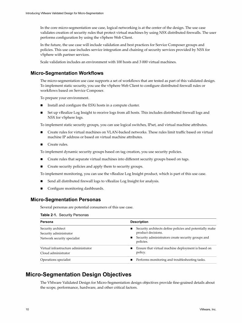
Micro-Segmentation PersonasSeveral personas are potential consumers of this use case.
Table 2‑1. Security Personas
Persona Description
Security architectSecurity administratorNetwork security specialist
n Security architects define policies and potentially makeproduct decisions.
n Security administrators create security groups andpolicies.
Virtual infrastructure administratorCloud administrator
n Ensure that virtual machine deployment is based onpolicy.
Operations specialist n Performs monitoring and troubleshooting tasks.
Micro-Segmentation Design ObjectivesThe VMware Validated Design for Micro-Segmentation design objectives provide fine-grained details aboutthe scope, performance, hardware, and other critical factors.
Introducing VMware Validated Design for Micro-Segmentation
10 VMware, Inc.
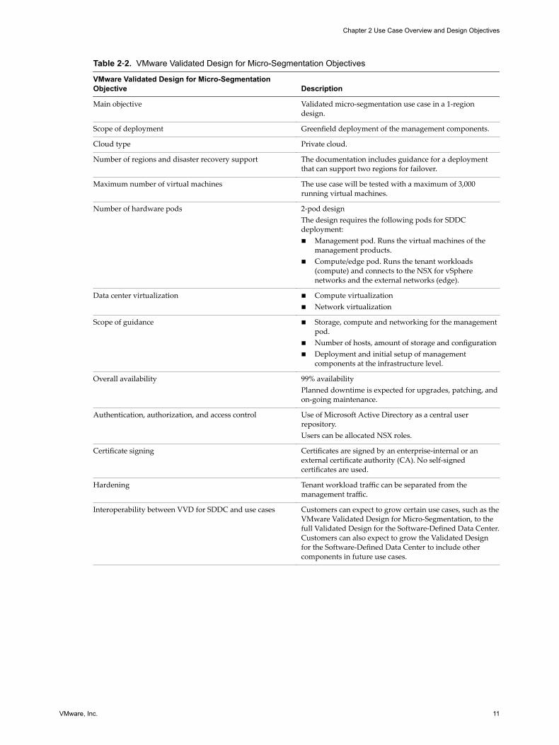
Table 2‑2. VMware Validated Design for Micro-Segmentation Objectives
VMware Validated Design for Micro-SegmentationObjective Description
Main objective Validated micro-segmentation use case in a 1-regiondesign.
Scope of deployment Greenfield deployment of the management components.
Cloud type Private cloud.
Number of regions and disaster recovery support The documentation includes guidance for a deploymentthat can support two regions for failover.
Maximum number of virtual machines The use case will be tested with a maximum of 3,000running virtual machines.
Number of hardware pods 2-pod designThe design requires the following pods for SDDCdeployment:n Management pod. Runs the virtual machines of the
management products.n Compute/edge pod. Runs the tenant workloads
(compute) and connects to the NSX for vSpherenetworks and the external networks (edge).
Data center virtualization n Compute virtualizationn Network virtualization
Scope of guidance n Storage, compute and networking for the managementpod.
n Number of hosts, amount of storage and configurationn Deployment and initial setup of management
components at the infrastructure level.
Overall availability 99% availabilityPlanned downtime is expected for upgrades, patching, andon-going maintenance.
Authentication, authorization, and access control Use of Microsoft Active Directory as a central userrepository.Users can be allocated NSX roles.
Certificate signing Certificates are signed by an enterprise-internal or anexternal certificate authority (CA). No self-signedcertificates are used.
Hardening Tenant workload traffic can be separated from themanagement traffic.
Interoperability between VVD for SDDC and use cases Customers can expect to grow certain use cases, such as theVMware Validated Design for Micro-Segmentation, to thefull Validated Design for the Software-Defined Data Center.Customers can also expect to grow the Validated Designfor the Software-Defined Data Center to include othercomponents in future use cases.
Chapter 2 Use Case Overview and Design Objectives
VMware, Inc. 11

Introducing VMware Validated Design for Micro-Segmentation
12 VMware, Inc.
Documentation Structure andAudience 3
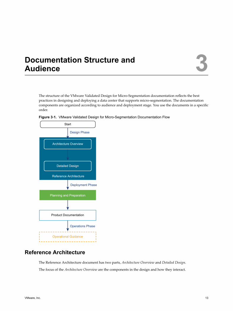
The structure of the VMware Validated Design for Micro-Segmentation documentation reflects the bestpractices in designing and deploying a data center that supports micro-segmentation. The documentationcomponents are organized according to audience and deployment stage. You use the documents in a specificorder.
Figure 3‑1. VMware Validated Design for Micro-Segmentation Documentation Flow
Architecture Overview
Detailed Design
Reference Architecture
Design Phase
Start
Deployment Phase
Planning and Preparation
Product Documentation
Operations Phase
Operational Guidance
Reference ArchitectureThe Reference Architecture document has two parts, Architecture Overview and Detailed Design.
The focus of the Architecture Overview are the components in the design and how they interact.
VMware, Inc. 13
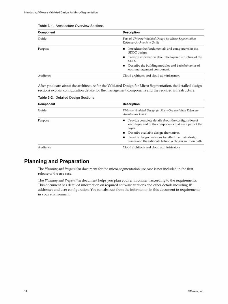
Table 3‑1. Architecture Overview Sections
Component Description
Guide Part of VMware Validated Design for Micro-SegmentationReference Architecture Guide
Purpose n Introduce the fundamentals and components in theSDDC design.
n Provide information about the layered structure of theSDDC.
n Describe the building modules and basic behavior ofeach management component.
Audience Cloud architects and cloud administrators
After you learn about the architecture for the Validated Design for Micro-Segmentation, the detailed designsections explain configuration details for the management components and the required infrastructure.
Table 3‑2. Detailed Design Sections
Component Description
Guide VMware Validated Design for Micro-Segmentation ReferenceArchitecture Guide
Purpose n Provide complete details about the configuration ofeach layer and of the components that are a part of thelayer.
n Describe available design alternatives.n Provide design decisions to reflect the main design
issues and the rationale behind a chosen solution path.
Audience Cloud architects and cloud administrators
Planning and PreparationThe Planning and Preparation document for the micro-segmentation use case is not included in the firstrelease of the use case.
The Planning and Preparation document helps you plan your environment according to the requirements.This document has detailed information on required software versions and other details including IPaddresses and user configuration. You can abstract from the information in this document to requirementsin your environment.
Introducing VMware Validated Design for Micro-Segmentation
14 VMware, Inc.
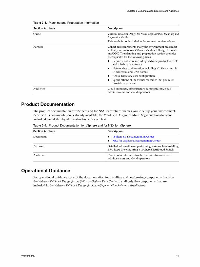
Table 3‑3. Planning and Preparation Information
Section Attribute Description
Guide VMware Validated Design for Micro-Segmentation Planning andPreparation Guide.This guide is not included in the August preview release.
Purpose Collect all requirements that your environment must meetso that you can follow VMware Validated Design to createan SDDC. The planning and preparation section providesprerequisites for the following areas:n Required software including VMware products, scripts
and third-party softwaren Networking configuration including VLANs, example
IP addresses and DNS namesn Active Directory user configurationn Specifications of the virtual machines that you must
provide in advance
Audience Cloud architects, infrastructure administrators, cloudadministrators and cloud operators
Product DocumentationThe product documentation for vSphere and for NSX for vSphere enables you to set up your environment.Because this documentation is already available, the Validated Design for Micro-Segmentation does notinclude detailed step-by-step instructions for each task.
Table 3‑4. Product Documentation for vSphere and for NSX for vSphere
Section Attribute Description
Documents n vSphere 6.0 Documentation Centern NSX for vSphere Documentation Center
Purpose Detailed information on performing tasks such as installingESXi hosts or configuring a vSphere Distributed Switch.
Audience Cloud architects, infrastructure administrators, cloudadministrators and cloud operators
Operational GuidanceFor operational guidance, consult the documentation for installing and configuring components that is inthe VMware Validated Design for the Software-Defined Data Center. Install only the components that areincluded in the VMware Validated Design for Micro-Segmentation Reference Architecture.
Chapter 3 Documentation Structure and Audience
VMware, Inc. 15

Introducing VMware Validated Design for Micro-Segmentation
16 VMware, Inc.
Components and Layers 4The design is tested with specific product versions and using a prescribed, layered architecture. Thearchitecture of all validated designs enables you to implement the design in modules and to handle each setof components separately. It also facilitates scaling, for example, from this micro-segmentation use case tothe full Software-Defined Data Center.
This chapter includes the following topics:
n “VMware Software Components in the Validated Design for Micro-Segmentation,” on page 17
n “Logical Design,” on page 18
n “Physical Infrastructure Layer,” on page 20
n “Virtual Infrastructure Layer,” on page 22
VMware Software Components in the Validated Design for Micro-Segmentation
VMware Validated Design for Micro-Segmentation is based on a set of VMware products. Because specificversions of each product are tested together, some of the product versions differ from the most recentversion that is available from the download page.
Table 4‑1. VMware Software in the VMware Validated Design for Microsegmentation
Product Group and Edition Product Name Product Version
VMware vSphere Enterprise Plus ESXi 6.0 Update 2
vCenter Server Appliance (ISO) 6.0 Update 2
VMware NSX for vSphere Enterprise NSX for vSphere 6.2.4
VMware vRealize Log Insight vRealize Log Insight 3.3.1
vRealize Log Insight Content Pack forNSX for vSphere
3.3
Product ConsiderationsUse the list of software components for VMware Validated Design under the certain considerations.VMware makes patches and releases available that address critical security issues for several products.Verify that you are using the latest security patches and releases for a given component when deployingVMware Validated Design.
VMware, Inc. 17
Logical DesignThe logical design of the micro-segmentation use case includes two clusters that are managed by vCenterServer systems and two transport zones.
The use case includes the following components, shown in the illustration below.
n Two vCenter Server instances manage the management cluster and the compute/edge cluster.
n Each cluster includes three ESXi hosts. If the design expands to use Virtual SAN, four ESXi hosts areneeded, as shown in the illustration below.
n Each ESXi host connects to the internal SDDC fabric and to the external network (Internet / MPLS)
n Through two logical switches, the clusters connect to two NSX transport zones, one for managementtraffic, and one for all other traffic.
n The management transport zone includes the following components:
n NSX Controller, NSX Edge, and NSX Manager instance for the management cluster.
n NSX Manager for the compute cluster.
n Other management applications. For the micro-segmentation use case, vRealize Log Insight is theonly application.
n The compute transport zone includes the following components:
n NSX Controller and NSX Edge instances for the compute cluster. The NSX Edge instance is part ofthe management transport zone.
n SDDC payload.
Introducing VMware Validated Design for Micro-Segmentation
18 VMware, Inc.
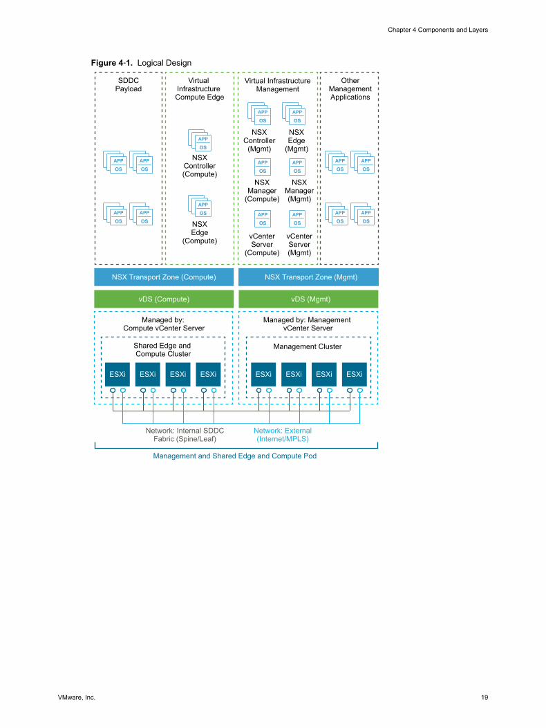
Figure 4‑1. Logical Design
APP
OSAPP
OS
APP
OSAPP
OS
APP
OSAPP
OS
APP
OSAPP
OS
APP
OS
APP
OS
APP
OSAPP
OS
ESXi ESXi
APP
OSAPP
OS
APP
OSAPP
OS
Virtual InfrastructureManagement
NSXController
(Mgmt)
OtherManagementApplications
NSXEdge
(Mgmt)
NSXManager(Mgmt)
NSXManager
(Compute)
NSXEdge
(Compute)
NSXController(Compute)
ESXi ESXi ESXi ESXi ESXi ESXi
SDDCPayload
Virtual Infrastructure Compute Edge
NSX Transport Zone (Compute)
vDS (Compute) vDS (Mgmt)
NSX Transport Zone (Mgmt)
Shared Edge and Compute Cluster
Management Cluster
Managed by: Compute vCenter Server
Managed by: Management vCenter Server
Network: External(Internet/MPLS)
Network: Internal SDDCFabric (Spine/Leaf)
Management and Shared Edge and Compute Pod
vCenterServer(Mgmt)
vCenterServer
(Compute)
Chapter 4 Components and Layers
VMware, Inc. 19
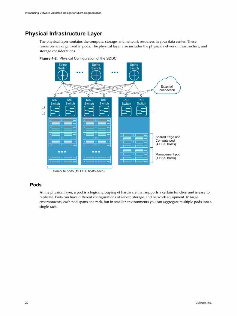
Physical Infrastructure LayerThe physical layer contains the compute, storage, and network resources in your data center. Theseresources are organized in pods. The physical layer also includes the physical network infrastructure, andstorage considerations.
Figure 4‑2. Physical Configuration of the SDDC
SpineSwitch
SpineSwitch
SpineSwitch
ToR Switch
ToR Switch
ToR Switch
ToR Switch
Compute pods (19 ESXi hosts each)
Shared Edge andCompute pod(4 ESXi hosts)
Management pod(4 ESXi hosts)
External connection
ToR Switch
ToR Switch
L2
L3
PodsAt the physical layer, a pod is a logical grouping of hardware that supports a certain function and is easy toreplicate. Pods can have different configurations of server, storage, and network equipment. In largeenvironments, each pod spans one rack, but in smaller environments you can aggregate multiple pods into asingle rack.
Introducing VMware Validated Design for Micro-Segmentation
20 VMware, Inc.
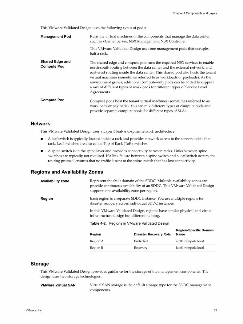
This VMware Validated Design uses the following types of pods:
Management Pod Runs the virtual machines of the components that manage the data center,such as vCenter Server, NSX Manager, and NSX Controller.
This VMware Validated Design uses one management pods that occupieshalf a rack.
Shared Edge andCompute Pod
The shared edge and compute pod runs the required NSX services to enablenorth-south routing between the data center and the external network, andeast-west routing inside the data center. This shared pod also hosts the tenantvirtual machines (sometimes referred to as workloads or payloads). As theenvironment grows, additional compute-only pods can be added to supporta mix of different types of workloads for different types of Service LevelAgreements.
Compute Pod Compute pods host the tenant virtual machines (sometimes referred to asworkloads or payloads). You can mix different types of compute pods andprovide separate compute pools for different types of SLAs.
NetworkThis VMware Validated Design uses a Layer 3 leaf-and-spine network architecture.
n A leaf switch is typically located inside a rack and provides network access to the servers inside thatrack. Leaf switches are also called Top of Rack (ToR) switches.
n A spine switch is in the spine layer and provides connectivity between racks. Links between spineswitches are typically not required. If a link failure between a spine switch and a leaf switch occurs, therouting protocol ensures that no traffic is sent to the spine switch that has lost connectivity.
Regions and Availability ZonesAvailability zone Represent the fault domain of the SDDC. Multiple availability zones can
provide continuous availability of an SDDC. This VMware Validated Designsupports one availability zone per region.
Region Each region is a separate SDDC instance. You use multiple regions fordisaster recovery across individual SDDC instances.
In this VMware Validated Design, regions have similar physical and virtualinfrastructure design but different naming.
Table 4‑2. Regions in VMware Validated Design
Region Disaster Recovery RoleRegion-Specific DomainName
Region A Protected sfo01.rainpole.local
Region B Recovery lax01.rainpole.local
StorageThis VMware Validated Design provides guidance for the storage of the management components. Thedesign uses two storage technologies:
VMware Virtual SAN Virtual SAN storage is the default storage type for the SDDC managementcomponents.
Chapter 4 Components and Layers
VMware, Inc. 21
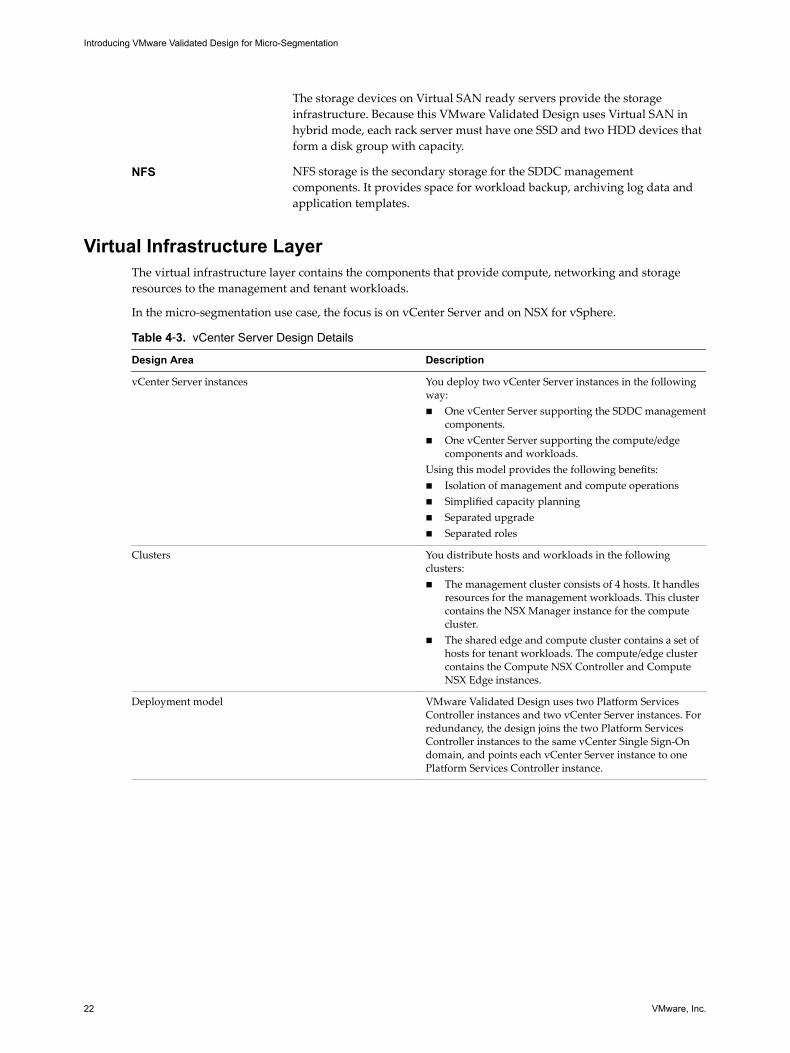
The storage devices on Virtual SAN ready servers provide the storageinfrastructure. Because this VMware Validated Design uses Virtual SAN inhybrid mode, each rack server must have one SSD and two HDD devices thatform a disk group with capacity.
NFS NFS storage is the secondary storage for the SDDC managementcomponents. It provides space for workload backup, archiving log data andapplication templates.
Virtual Infrastructure LayerThe virtual infrastructure layer contains the components that provide compute, networking and storageresources to the management and tenant workloads.
In the micro-segmentation use case, the focus is on vCenter Server and on NSX for vSphere.
Table 4‑3. vCenter Server Design Details
Design Area Description
vCenter Server instances You deploy two vCenter Server instances in the followingway:n One vCenter Server supporting the SDDC management
components.n One vCenter Server supporting the compute/edge
components and workloads.Using this model provides the following benefits:n Isolation of management and compute operationsn Simplified capacity planningn Separated upgraden Separated roles
Clusters You distribute hosts and workloads in the followingclusters:n The management cluster consists of 4 hosts. It handles
resources for the management workloads. This clustercontains the NSX Manager instance for the computecluster.
n The shared edge and compute cluster contains a set ofhosts for tenant workloads. The compute/edge clustercontains the Compute NSX Controller and ComputeNSX Edge instances.
Deployment model VMware Validated Design uses two Platform ServicesController instances and two vCenter Server instances. Forredundancy, the design joins the two Platform ServicesController instances to the same vCenter Single Sign-Ondomain, and points each vCenter Server instance to onePlatform Services Controller instance.
Introducing VMware Validated Design for Micro-Segmentation
22 VMware, Inc.