introducing the autocad 2d interfaceintroducing the autocad 2d interface after completing this...
TRANSCRIPT

Introducing the AutoCAD 2D Interface
After completing this chApter, you will understAnd:
The 2D interface of AutoCAD 2008, 2009, and 2010 t
The differences between the AutoCAD Workspaces for 2D drawing t
Some of the pertinent new features of each release t
Chapter 1
38855c01.indd 1 1/11/10 9:32:58 PM
COPYRIG
HTED M
ATERIAL

2 ChApter 1: IntroDuCIng the AutoCAD 2D InterfACe
Figure 1.2: Ω AutoCAD 2008: the AutoCAD Classic Workspace
Figure 1.3: Ω AutoCAD 2009: the AutoCAD Classic Workspace
When this book was written, AutoCAD 2010 was the current AutoCAD release.
Because significant changes were made to the AutoCAD 2008 and 2009 interface,
understanding those changes is prudent. AutoCAD usually releases a new version
of AutoCAD every year. With each new release, toolbars, commands, and the user
interface are enhanced. Sometimes these changes are significant. Because these
new features can help you streamline the drawing process and increase productivity,
you should explore them and become familiar with them. typically, a new features
Workshop prompt will launch the first time AutoCAD is opened, allowing you the
option to review the new features or wait until later. (See figure 1.1.) these new fea-
tures can also be accessed via the AutoCAD help menu at any time.
Figure 1.1: Ω the AutoCAD 2010 new features Workshop window
If you have been using an earlier release of AutoCAD, chances are that you have
been interacting with the software via the AutoCAD Classic Workspace and are
familiar with it. Although this workspace is still available, the significant new features
for each new release are accessed via the 2D Drafting and Annotation Workspace.
While all of the commands can still be accessed using either the command line or
the pulldown menus via the AutoCAD Classic Workspace, it is prudent to become
familiar with the 2D Drafting and Annotation Workspace for 2D drawing. You can
toggle your display between these workspaces. (See figures 1.2 through 1.4.)
38855c01.indd 2 1/11/10 9:32:58 PM

AutoCAD 2008 3
Figure 1.5: Ω AutoCAD 2008: Launching the 2D Drafting and Annotation Workspace
this action will launch a menu of workspaces from which to choose.
2. position the cursor over the 2D Drafting and Annotation Workspace option and
click on it with the left mouse button.
this action will launch the 2D Drafting and Annotation Workspace (figures 1.6
and 1.7). Some of its significant new 2D drawing features are listed here:
the Information Center•
the Dashboard•
the addition of Annotation Scaling and Visibility to the Status toolbar•
the Clean Screen icon•
the Maximize/Minimize Viewport icon in layout space•
The Dashboard
The Information Center
The Clean Screen IconThe Annotation
Scaling and Visibility Icons
Figure 1.6: Ω AutoCAD 2008: the 2D Drafting and Annotation Workspace’s significant features in model space
Figure 1.4: Ω AutoCAD 2010: the AutoCAD Classic Workspace
If you are proficient with a recent AutoCAD release, you should have little dif-
ficulty getting up to speed. this chapter will provide an overview of some of the
newest 2D drawing features of AutoCAD for releases 2008, 2009, and 2010. refer
to the particular AutoCAD release you wish to learn. for the most part, the instruc-
tions assume that you are familiar with AutoCAD. All of the instructions utilize the 2D
Drafting and Annotation Workspace. Although this chapter reviews releases 2008
and 2009, later chapters will focus on AutoCAD 2010 and its features.
AutoCAD 2008
Major 2D drawing capabilities were added to the release of AutoCAD 2008—
annotative documentation, in particular. this new feature allows you to add notes,
tags, symbols, dimensions, etc. at the appropriate size for the scale of your drawing.
Annotative documentation takes the guesswork out of the equation and ensures
global standardization based on the scale of the drawing.
to begin, start by launching AutoCAD 2008 either via the icon on your desktop or
using the Start menu. the 2D Drafting and Annotation Workspace might load when
your version of AutoCAD 2008 is launched. If it does not load, do the following:
1. position the cursor over the Workspaces toolbar menu located at the top-left of the
model space interface and click on it with the left mouse button. (See figure 1.5.)
38855c01.indd 3 1/11/10 9:32:58 PM
4 ChApter 1: IntroDuCIng the AutoCAD 2D InterfACe
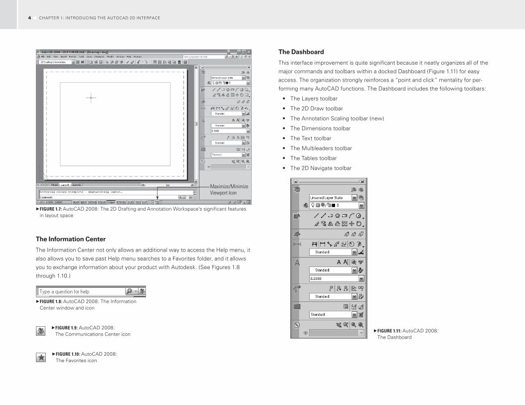
The Dashboard
this interface improvement is quite significant because it neatly organizes all of the
major commands and toolbars within a docked Dashboard (figure 1.11) for easy
access. the organization strongly reinforces a “point and click” mentality for per-
forming many AutoCAD functions. the Dashboard includes the following toolbars:
the Layers toolbar•
the 2D Draw toolbar•
the Annotation Scaling toolbar (new)•
the Dimensions toolbar•
the text toolbar•
the Multileaders toolbar•
the tables toolbar•
the 2D navigate toolbar•
Figure 1.11: Ω AutoCAD 2008: the Dashboard
Maximize/Minimize Viewport Icon
Figure 1.7: Ω AutoCAD 2008: the 2D Drafting and Annotation Workspace’s significant features in layout space
The Information Center
the Information Center not only allows an additional way to access the help menu, it
also allows you to save past help menu searches to a favorites folder, and it allows
you to exchange information about your product with Autodesk. (See figures 1.8
through 1.10.)
Figure 1.8: Ω AutoCAD 2008: the Information Center window and icon
Figure 1.9: Ω AutoCAD 2008: the Communications Center icon
Figure 1.10: Ω AutoCAD 2008: the favorites icon
38855c01.indd 4 1/11/10 9:32:59 PM

AutoCAD 2008 5
A layer must be locked before it can be faded. this action will automatically fade
any layer in the drawing that is currently locked. When the layers appear in their
faded state, the visible geometry can utilize osnaps. Additionally, the fade can be
adjusted and toggled between on and off by clicking the AutoCAD Lock icon.
The 2D Draw Toolbar
the 2D Draw toolbar (figure 1.14) allows access to all of the 2D drawing and modify-
ing icons via the Dashboard. the top row consists of all of the drawing icons, and the
bottom row consists of all of the modifying icons.
Figure 1.14: Ω AutoCAD 2008: the Dashboard’s 2D Draw toolbar
to access additional drawing icons, do the following:
1. In the 2D Draw toolbar, position the cursor over the pulldown arrow at the end
of the top row of icons and click it with the left mouse button.
this action will launch a flyout menu (figure 1.15) showing the additional drawing
icons.
Figure 1.15: Ω AutoCAD 2008: the Dashboard’s 2D Draw toolbar and the Additional Drawing Icons flyout menu
The Layers Toolbar
this toolbar still allows access to the Layer properties Manager, as well as various
other layer functions available to you, such as the function to isolate a layer or to set
a layer current. (See figure 1.12.)
Figure 1.12: Ω AutoCAD 2008: the Dashboard’s Layer toolbar
As an added feature, the Layers toolbar allows layers to be faded within model
space and active viewports within layout tabs. to access this option, do the
following:
1. position the cursor over the Layers icon and click on it with the left mouse but-
ton to expand the toolbar (figure 1.13).
Figure 1.13: Ω AutoCAD 2008: the Dashboard’s Layer toolbar (expanded)
reducing the visual complexity in a drawing is referred to as fading layers. this
technique can be useful when you need to keep specific layers active in a drawing in
order to add information that may be contingent on the placement of items already
drawn. for example, you might want to fade the furniture layer of a drawing in order
to add electrical or lighting information, because the placement of the furniture might
need to be visible in order to line up electrical outlets or center lighting fixtures, etc.
38855c01.indd 5 1/11/10 9:32:59 PM

6 ChApter 1: IntroDuCIng the AutoCAD 2D InterfACe
now whenever any annotation is added to model space, it can be added with
an annotative property. this property will automatically define the appropriate size
of an object, text, or dimension style based on the chosen scale of your drawing in
a Layout tab. Additional scales can be defined or deleted, and based on the scale
of a given viewport, they will display appropriately. prior to inserting any annota-
tive object into the drawing, make sure to check the Annotation Visibility controls.
these icons are located on the Status toolbar at the bottom-right of the AutoCAD
interface. In order for the annotative objects to be visible when inserted into the
drawing, these settings need to be turned on. to verify that they are, do the
following:
1. refer to the lower-right of the Status toolbar to visually verify that the Annota-
tion Visibility icon is on. (See figure 1.19.)
this is easy to determine. If the Sun icon appears, then Annotation Visibility is
on. this designation will show annotative objects for all scales.
Figure 1.19: Ω AutoCAD 2008: the Annotation Visibility icons
If the Sun icon is shaded, the annotative objects will appear for the current scale
only. If the icon is shaded, do the following:
1. position the cursor over the Annotation Visibility icon and click on it with the left
mouse button.
Also, verify that the Annotation icon located directly adjacent to the Annotation
Visibility icon is also set to the on position. When this icon is set to the on position,
it will appear with a yellow lightning bolt and AutoCAD will automatically add scales
to annotative objects when the annotation scale changes. If this setting is not set
accordingly, follow the previous step.
Symbols can be accessed using the Annotation Scaling toolbar. to access the
tool palettes of the available symbols (figure 1.20), do the following:
1. position the cursor over the Annotation Scaling icon in the Annotation Scaling
toolbar on the Dashboard, and click on it with the left mouse button.
Additional modifying icons can be accessed similarly. (See figure 1.16.)
Figure 1.16: Ω AutoCAD 2008: the Dashboard’s 2D Draw toolbar and the Additional Modifying Icons flyout menu
The Annotation Scaling Toolbar
Annotations are any items (such as symbols, text, and dimensions) added to a draw-
ing. Scaling these objects has become significantly easier with the Annotation Scal-
ing toolbar (figures 1.17 and 1.18).
Figure 1.17: Ω AutoCAD 2008: the Dashboard’s Annotation Scaling toolbar
Figure 1.18: Ω AutoCAD 2008: the Dashboard’s Annotation Scaling icon
38855c01.indd 6 1/11/10 9:32:59 PM

AutoCAD 2008 7
to change the annotation scale to ¼″ = 1′-0″ of that symbol, do the following:
3. position the cursor over the pulldown arrow of the Annotation Scale control,
scroll through the menu, select ¼″ = 1′-0″, and click on it with the left mouse
button. Click the oK button with the left mouse button, and select an insertion
point in the drawing by clicking it with the left mouse button.
this action will insert the symbol within model space at the correct size for a
drawing, which will ultimately be plotted at a scale of ¼″ = 1′-0″ and end the com-
mand. (See figure 1.22.)
Figure 1.22: Ω AutoCAD 2008: An annotation tag inserted in the drawing
An Annotative icon (figure 1.23) will appear when the cursor is positioned over
an object that has annotative properties.
Figure 1.23: Ω AutoCAD 2008: Annotative icon
the Annotation Scale of the drawing will be updated to ¼″ = 1′-0″. refer to the
Status toolbar in the lower-right corner of the model space interface (figure 1.24).
Figure 1.24: Ω AutoCAD 2008: Annotation Scale in the Status toolbar
Additional scales can also be added to annotative objects from the Annotation
Scaling toolbar (figure 1.25).
Figure 1.20: Ω AutoCAD 2008: the Annotation Scaling tool palettes
to insert a symbol into a drawing, do the following:
2. position the cursor over the desired symbol in the Annotation tab on the tool
palette and click on it with the left mouse button.
this action will launch the Select Annotation Scale window (figure 1.21). It will
automatically default to a scale of 1:1.
Figure 1.21: Ω AutoCAD 2008: the Select Annotation Scale window
38855c01.indd 7 1/11/10 9:32:59 PM

8 ChApter 1: IntroDuCIng the AutoCAD 2D InterfACe
The Tables Toolbar
the tables toolbar (figure 1.29) still allows you to add tables to your drawing, as well
as other enhancements to create better quality tables with the addition of options
such as borders and margins.
Figure 1.29: Ω AutoCAD 2008: the tables toolbar
The 2D Navigate Toolbar
the 2D navigate toolbar (figure 1.30) still allows you to zoom into and pan across
your drawing in real time.
Figure 1.30: Ω AutoCAD 2008: the 2D navigate toolbar
Clean Screen
As you may have noticed, the drawing display area in the 2D Drafting and Annota-
tion Workspace is somewhat limited because of the addition of the Dashboard.
there are two options to remedy this. the first option is to simply modify the size
of the Dashboard by stretching its limits, or you can use the Clean Screen icon. the
Clean Screen icon (figure 1.31) is significantly easier to use, and it allows you to
toggle back and forth. the Clean Screen function basically hides all of the toolbars
within the display, allowing the drawing space to take over the complete display
(figure 1.32).
Figure 1.31: Ω AutoCAD 2008: the Clean Screen icon
to start the Clean Screen function, do the following:
1. position the cursor over the Clean Screen icon in the bottom-right corner of the
display, and click on it with the left mouse button.
Figure 1.25: Ω AutoCAD 2008: the Add/Delete Scales icon
The Dimensions Toolbar
the Dimensions toolbar (figure 1.26) still allows you to add all of the various dimen-
sions to a drawing, as well as some new enhancements such as adding a jog to
a linear dimension and breaking an extension line when it intersects with existing
geometry. Additionally, dimensions can be added to a drawing as annotative objects.
Figure 1.26: Ω AutoCAD 2008: the Dimensions toolbar
The Text Toolbar
the text toolbar (figure 1.27) allows you to add multiline and single text to a draw-
ing, as well as new text styles. An additional enhancement is the Spell Check option.
Additionally, text can be added to a drawing as annotative objects.
Figure 1.27: Ω AutoCAD 2008: the text toolbar
The Multileaders Toolbar
the Multileaders toolbar (figure 1.28) allows you to add a multileader style, as well
as arrange and align leaders in the drawing.
Figure 1.28: Ω AutoCAD 2008: the Multileaders toolbar
38855c01.indd 8 1/11/10 9:32:59 PM

AutoCAD 2008 9
to practice using this tool, make sure that your display is set to a Layout tab and
do the following:
1. position the cursor over the Maximize Viewport icon, and click on it with the left
mouse button.
this action will maximize the viewport of the current Layout tab (figure 1.35). It
will appear as a red, dashed border. to deselect the viewport, do the following:
Figure 1.35: Ω AutoCAD 2008: the viewport is maximized.
2. position the cursor over the Minimize Viewport icon, and click on it with the left
mouse button.
this action will return the display to the Layout tab and deactivate the viewport.
Figure 1.32: Ω AutoCAD 2008: the Clean Screen results
to disengage the Clean Screen function, do the following:
2. position the cursor over the Clean Screen icon in the bottom-right corner of the
display, and click on it with the left mouse button.
this action will return the display to the 2D Drafting and Annotation Workspace.
Maximize/Minimize Viewport
the Maximize/Minimize icon (figures 1.33 and 1.34) is a significant enhancement to
the Layout tab. this icon easily allows you to select/activate a viewport within any
Layout tab.
Figure 1.33: Ω AutoCAD 2008: the Maximize Viewport icon
Figure 1.34: Ω AutoCAD 2008: the Minimize Viewport icon
38855c01.indd 9 1/11/10 9:32:59 PM

10 ChApter 1: IntroDuCIng the AutoCAD 2D InterfACe
The StandardAnnotation Toobar
The MenuBrowser
The Ribbon
Figure 1.38: Ω AutoCAD 2009: the 2D Drafting and Annotation Workspace’s significant features in model space
The Menu Browser
the Menu browser neatly organizes the dropdown menus that formerly appeared
at the top of the model space interface within the AutoCAD Classic Workspace. Its
icon (figure 1.39) is located at the top-left of the model space interface.
Figure 1.39: Ω AutoCAD 2009: the Menu Browser icon
to access the Menu browser, do the following:
1. position the cursor over the Menu Browser icon located at the top-left of the
model space interface, and click on it with the left mouse button.
AutoCAD 2009
the first thing you will notice is that the AutoCAD 2009 user interface has changed
dramatically. Interacting with AutoCAD is much the same as interacting with the
new Microsoft office 2007 interface. the Dashboard has been replaced with a
ribbon that neatly organizes all of the commands you will use. the goal is to visually
present the tools in a concise manner, thereby increasing the end user’s productivity.
to begin, start by launching AutoCAD 2009 either via the icon on your desktop or
via the Start menu. the 2D Drafting and Annotation Workspace may load when your
version of AutoCAD 2009 is launched. If it does not load, do the following:
1. position the cursor over the pulldown menu of the Workspaces toolbar located
at the upper-left of the model space interface, or access the Workspace Switch-
ing icon (figure 1.36 and figure 1.37) in the lower-right of the model space
interface on the Status toolbar. Click it with the left mouse button.
Figure 1.36: Ω AutoCAD 2009: Launching the 2D Drafting and Annotation Workspace
Figure 1.37: Ω AutoCAD 2009: the Workspace Switching icon
this action will launch a menu of workspaces from which to choose.
2. position the cursor over the 2D Drafting and Annotation Workspace option, and
click on it with the left mouse button.
this action will launch the 2D Drafting and Annotation Workspace. Some of the
significant new 2D drawing features (figure 1.38) are listed here:
the Menu browser•
the ribbon •
the Standard Annotation toolbar •
Improvements made to the Status toolbar •
Improved tooltips•
38855c01.indd 10 1/11/10 9:33:00 PM

AutoCAD 2009 11
When the 2D Drafting and Annotation Workspace launches, the home tab is the
active tab on the ribbon. this tab houses all of the basic commands used to draw
and modify objects, annotate objects (add text and dimensions), and access layer
controls. A new feature has been added to AutoCAD 2009 that allows the user to pin
an action or a toolbar. this feature works in a fashion similar to the flyout menus you
may be used to using. the major difference is that it allows the user to actually pin
the expanded toolbar. to pin a toolbar on the home tab, do the following:
1. hover the cursor over the Modify toolbar on the home tab of the ribbon (fig-
ure 1.42), and click on the pulldown arrow in the lower-right corner with the left
mouse button.
Side View of Push Pin
Figure 1.42: Ω AutoCAD 2009: the Modify toolbar (prior to pin)
this action will launch the additional icons located on the Modify toolbar. the
push pin icon is located in the lower-right corner of the toolbar. In order to pin this
toolbar, simply do the following:
2. hover the cursor over the side-view push pin icon, and click on it with the left
mouse button to pin the toolbar in place. (See figure 1.43.)
Top View of Push Pin
Figure 1.43: Ω AutoCAD 2009: the Modify toolbar (pinned in place)
this action will open the Menu browser and allow access to commands in a way
similar to that of the dropdown menus of the AutoCAD Classic Workspace. to inter-
act with AutoCAD via the Menu browser (figure 1.40), simply do the following:
2. hover the cursor over the category to access, position the cursor over the com-
mand to launch, and click on it with the left mouse button.
Figure 1.40: Ω AutoCAD 2009: the Menu browser (expanded)
The Ribbon
Keeping in step with the new Microsoft office 2007 interface, the new ribbon
replaces the Dashboard panel. now all of the commands can be accessed using the
ribbon tabs located at the top of the user interface. (See figure 1.41.)
Figure 1.41: Ω AutoCAD 2009: the ribbon’s home tab
38855c01.indd 11 1/11/10 9:33:00 PM

12 ChApter 1: IntroDuCIng the AutoCAD 2D InterfACe
Figure 1.46: Ω AutoCAD 2009: the ribbon’s tools tab
The View Tab
the View tab (figure 1.47) houses the toolbars to change the universal Coordinate
System (uCS) designation of the drawing file, as well as the toolbar to create and
modify viewports.
Figure 1.47: Ω AutoCAD 2009: the ribbon’s View tab
The Output Tab
the output tab (figure 1.48) houses the toolbars to plot/publish and transmit the
drawing file.
Figure 1.48: Ω AutoCAD 2009: the ribbon‘s output tab
The Standard Annotation Toolbar
the Standard Annotation toolbar (docked directly below the ribbon) houses the
frequently used commands such as new, Save, open, undo/redo. this toolbar
(figure 1.49) offers quick access to these commands.
Figure 1.49: Ω AutoCAD 2009: the Standard Annotation toolbar
the pin will change to a top view. to return the toolbar to the previous position on
the ribbon, do the following:
3. hover the cursor over the top-view push pin icon, and click on it with the left
mouse button to return the toolbar to the ribbon.
the ribbon contains other categories of toolbars, which are described in the fol-
lowing text.
The Blocks and References Tab
the Blocks and references tab (figure 1.44) houses the toolbars to create and edit
blocks and block attributes, as well as attaching images and external references to
the AutoCAD file.
Figure 1.44: Ω AutoCAD 2009: the ribbon’s Blocks and references tab
The Annotate Tab
the Annotate tab (figure 1.45) houses the toolbars to dimension and add text to the
file, as well as the toolbars, to create tables and multileaders and add or adjust anno-
tation scales.
Figure 1.45: Ω AutoCAD 2009: the ribbon’s Annotate tab
The Tools Tab
the tools tab (figure 1.46) houses the toolbars to customize, query, and audit the
drawing file.
38855c01.indd 12 1/11/10 9:33:01 PM

AutoCAD 2010 13
Figure 1.53: Ω AutoCAD 2009: the tooltip window (expanded)
AutoCAD 2010
AutoCAD 2008 and 2009 set a fast pace with improvements to the 2D AutoCAD;
AutoCAD 2010 takes the AutoCAD 2009 interface a bit further. Because the new
Microsoft office 2007–style interface has been retained, you will notice a signifi-
cantly expanded ribbon. Some tools and commands have been improved and
are easily accessed to reinforce end user productivity. one such improvement is
dynamic blocks: it is now possible to edit a block in place without creating a whole
new block to accommodate a different size or shape of a given component in that
block. Another significant improvement is that pDf files can now be used as under-
lays in an AutoCAD drawing. In addition, the Menu browser and Application menu
have been completely remodeled.
this portion of the chapter will offer a significantly abbreviated introduction
because the balance of the book will cover the advanced improvements in AutoCAD
2010.
to begin, start by launching AutoCAD 2010 either via the icon on your desktop or
via the Start menu. the 2D Drafting and Annotation Workspace may load when your
version of AutoCAD 2010 is launched. If it does not load, do the following:
1. position the cursor over the pulldown menu of the Workspace Switching icon in
the lower-right of the model space interface on the Status toolbar (figure 1.54).
Click it with the left mouse button.
The Status Toolbar
the Status toolbar (located at the bottom of the model space interface) has been
updated significantly. this toolbar (figure 1.50) houses all of the icons from the for-
mer releases of AutoCAD, and new icons have been added to it. It is now possible to
access 2D navigation tools to pan and zoom, control the annotation visibility of items
in the drawing file, and access layout space as well. object snaps are still located on
the Status toolbar. You can now choose to display them as icons (figure 1.51).
Figure 1.50: Ω AutoCAD 2009: the Status toolbar
to change the object snap’s radio buttons to icons, do the following:
1. hover the cursor over any of the object snaps, and click the radio button with
the right mouse button.
this action will launch a tooltip window.
2. hover the cursor over the use Icons option, and click on it with the left mouse
button to change the appearance of the object snaps to icons.
Figure 1.51: Ω AutoCAD 2009: on the Status toolbar, object snaps are displayed as icons.
Improved Tooltips
AutoCAD’s tooltips have also been dramatically improved. With a focus on productiv-
ity, the improved tooltips provide an easy way to learn more about a particular icon
without having to access the help menu. As in the past, when you hover the cursor
over a particular icon, a small tooltip window will appear with the name of that icon.
now, when you hover the cursor over any icon, a small tooltip window appears with
the name of the icon and a brief explanation. the longer the cursor hovers over the
icon, the more additional information appears. (See figures 1.52 and 1.53.)
Figure 1.52: Ω AutoCAD 2009: the tooltip window
38855c01.indd 13 1/11/10 9:33:01 PM

14 ChApter 1: IntroDuCIng the AutoCAD 2D InterfACe
The Menu Browser
the Menu browser has been completely remodeled. this new browser basically
houses all of the commands that were formerly found on the file pulldown menu.
In addition, the Application menu for the corresponding command prompts has also
been remodeled. the Menu Browser icon (figure 1.56) is located at the top of the
model space interface within the AutoCAD Classic Workspace. this icon is located
at the top-left corner of the model space interface.
Figure 1.56: Ω AutoCAD 2010: the Menu Browser icon
to access the Menu browser, do the following:
1. position the cursor over the Menu Browser icon located at the top-left of the
model space interface, and click on it with the left mouse button.
this action will open the Menu browser (figure 1.57), allowing access to com-
mands in a way similar to that of the dropdown menus in the AutoCAD Classic Work-
space. to interact with AutoCAD using the Menu browser, simply do the following:
2. hover the cursor over the category to access, position the cursor over the com-
mand to launch, and click on it with the left mouse button.
Figure 1.57: Ω AutoCAD 2010: the Menu browser (expanded)
Figure 1.54: Ω AutoCAD 2010: the Workspace Switching icon
this action will launch a menu of workspaces from which to choose.
2. position the cursor over the 2D Drafting and Annotation Workspace option, and
click on it with the left mouse button.
this action will launch the 2D Drafting and Annotation Workspace (figure 1.55).
Some of the significant new 2D drawing features are listed here:
the Menu browser (completely remodeled)•
the Application menu (completely remodeled)•
the Quick Access toolbar•
An improved help menu •
the ribbon (completely expanded)•
The Ribbon
The MenuBrowser
The Quick Access Toolbar
Figure 1.55: Ω AutoCAD 2010: the 2D Drafting and Annotation Workspace’s significant features in model space
38855c01.indd 14 1/11/10 9:33:01 PM

AutoCAD 2010 15
2. position the cursor over the AutoCAD Drawing option, and then click on it with
the left mouse button. (See figure 1.59.)
Figure 1.59: Ω AutoCAD 2010: Saving a drawing file as an AutoCAD drawing
this action will allow the drawing to be saved as an AutoCAD drawing. Simply
follow the typical steps to save the file.
The Quick Access Toolbar
the Quick Access toolbar (docked to the right of the Menu Browser icon) houses the
frequently used commands such as new, Save, open, and undo/redo. this toolbar
offers quick access to these commands. (See figures 1.60 and 1.61.)
Figure 1.60: Ω AutoCAD 2010: the Quick Access toolbar
The Application Menu
the Application Menu browser (figure 1.58) has been completely remodeled too.
now, when the Menu browser is accessed, the Application Menu browser launches
with larger icons and an explanation of the function.
Figure 1.58: Ω AutoCAD 2010: the Application Menu browser (expanded)
to access the Application Menu browser once the Menu browser has been
expanded, do the following:
1. position the cursor over the Save As category located on the Menu browser,
and click on it with the left mouse button.
this action will launch an expanded view of the Save As function. to interact with
AutoCAD via this menu, simply do the following:
38855c01.indd 15 1/11/10 9:33:01 PM

16 ChApter 1: IntroDuCIng the AutoCAD 2D InterfACe
Help Menu Improvement
You can still access information about AutoCAD commands and tools either using
the Information Center located at the top-right of the model space interface or by
pressing the f1 key on the keyboard. Although these methods are useful, you have
to access the Contents, Index, or Search tabs in the help menu. Sometimes these
search options list an unrelated item or you need to scroll through many items to find
the information you need. however, you don’t have to go to so much trouble any-
more. now you can find information about a particular icon with minimal effort.
for example, to find additional information about the Line icon, do the following:
1. hover the cursor over the Line icon and press the f1 key on the keyboard.
this action will launch the section of the help menu that refers to information
about the Line icon. (See figure 1.63.)
Figure 1.63: Ω AutoCAD 2010: the improved help Menu window
Figure 1.61: Ω AutoCAD 2010: the Quick Access toolbar (expanded)
not only can basic commands be accessed via this toolbar, but it is totally cus-
tomizable. the basic commands (which are listed) can be removed from the toolbar
and additional commands/icons can be added. to customize this toolbar, do the
following:
1. hover the cursor over the pulldown arrow tab located on the right side of the
Quick Access toolbar, and click on it with the left mouse button.
this action will launch the Customize Quick Access toolbar tooltip window. note
that all of the icons that appear on the toolbar have a check mark to the right of the
name of the command in this tooltip window. In order to remove an icon from the
toolbar, do the following:
2. hover the cursor over the command option for plot, and click on it with the left
mouse button.
this action will remove the plot icon from the Quick Access toolbar and allow you
to customize the toolbar with an additional icon if you like (figure 1.62).
Figure 1.62: Ω AutoCAD 2010: the Quick Access toolbar (without the plot icon)
to return the plot icon to the Quick Access toolbar, do the following:
3. hover the cursor over the pulldown arrow tab located on the right side of the Quick
Access toolbar, and click on it with the left mouse button. then, hover the cursor
over the command option for plot, and click on it with the left mouse button.
38855c01.indd 16 1/11/10 9:33:01 PM

AutoCAD 2010 17
The Parametric Tab
the parametric tab (figure 1.67) houses the toolbars used to draw with geometric
and dimensional constraints. Basically, this toolbar allows you to draw 2D geometry
with a restriction on particular elements or associations of a given object based on
the relationship of a given angle, dimension, or size and distance of an object, etc.
this ability is useful in the manufacturing field.
Figure 1.67: Ω AutoCAD 2010: the ribbon‘s parametric tab
The View Tab
the View tab (figure 1.68) houses the toolbars used to change the uCS designation
of the drawing file, the toolbar to create and modify viewports, and the toolbar to
control the Status toolbar.
Figure 1.68: Ω AutoCAD 2010: the ribbon’s View tab
The Manage Tab
the Manage tab (figure 1.69) houses the toolbars used to customize AutoCAD.
Figure 1.69: Ω AutoCAD 2010: the ribbon’s output tab
The Ribbon (Expanded)
Keeping in step with the new Microsoft office 2007–style interface, the new ribbon
replaces the Dashboard panel. now all of the commands can be accessed via the
ribbon tabs located at the top of the user interface. (See figure 1.64.)
Figure 1.64: Ω AutoCAD 2010: the ribbon’s home tab
When the 2D Drafting and Annotation Workspace launches, the home tab is the
active tab on the ribbon. this tab houses all of the basic commands used to draw
and modify objects, as well as annotate objects (add text and dimensions to objects)
and layer controls. A measuring toolbar is also added to this tab.
The Insert Tab
the Insert tab (figure 1.65) houses the toolbars used to create and edit blocks and
block attributes, as well as attach images and external references to an AutoCAD
file.
Figure 1.65: Ω AutoCAD 2010: the ribbon’s Insert tab
The Annotate Tab
the Annotate tab (figure 1.66) houses the toolbars used to dimension and add text
to the file, as well as the toolbars to create tables and multileaders and to add/adjust
annotation scales.
Figure 1.66: Ω AutoCAD 2010: the ribbon’s Annotate tab
38855c01.indd 17 1/11/10 9:33:02 PM

18 ChApter 1: IntroDuCIng the AutoCAD 2D InterfACe
The Output Tab
the output tab (figure 1.70) houses the toolbars used to plot/publish and transmit a
drawing file.
Figure 1.70: Ω AutoCAD 2010: the ribbon‘s output tab
The Express Tools Tab
the express tools tab (figure 1.71) houses toolbars with additional options that let
you perform expanded commands such as placing text on an arc or enclosing it in a
circle.
Figure 1.71: Ω AutoCAD 2010: the ribbon‘s express tools tab
38855c01.indd 18 1/11/10 9:33:02 PM