introducing adafruit feather rp2040
TRANSCRIPT
Introducing Adafruit Feather RP2040Created by Kattni Rembor
Last updated on 2021-07-21 12:22:58 PM EDT

26
1213141414151515151616161616171718191922222525262628282930323233333434363637383839394040404242444545
Guide Contents
Guide ContentsOverviewPinouts
Power Pins and ConnectionsLogic Pins
I2C and SPI on RP2040PWM on RP2040Analog PinsDigital PinsCircuitPython Pins vs GPxx PinsCircuitPython I2C, SPI and UART
GPIO Pins by Pin FunctionalityI2C PinsSPI PinsUART PinsPWM Pins
Microcontroller and FlashButtons and RST PinLEDsSTEMMA QTDebug Interfaces
AssemblyHeader Options!Soldering in Plain Headers
Prepare the header strip:Add the breakout board:And Solder!
Soldering on Female HeaderTape In PlaceFlip & Tack SolderAnd Solder!
Power ManagementBattery + USB PowerPower suppliesMeasuring BatteryENable pinAlternative Power OptionsInstall CircuitPython
CircuitPython QuickstartSafe Mode
Entering Safe Mode in CircuitPython 6.xEntering Safe Mode in CircuitPython 7.xIn Safe Mode
Flash Resetting UF2Installing Mu EditorDownload and Install MuUsing MuCreating and Editing Code
Creating CodeEditing Code
Your code changes are run as soon as the file is done saving.1. Use an editor that writes out the file completely when you save it.
© Adafruit Industries https://learn.adafruit.com/adafruit-feather-rp2040-pico Page 2 of 122

46464748484849495051515252535455596263636364656667686970717173737474747576777878797979798080808181828384
2. Eject or Sync the Drive After WritingOh No I Did Something Wrong and Now The CIRCUITPY Drive Doesn't Show Up!!!
Back to Editing Code...Exploring Your First CircuitPython Program
Imports & LibrariesSetting Up The LEDLoop-de-loopsWhat Happens When My Code Finishes Running?What if I don't have the loop?
More ChangesNaming Your Program FileConnecting to the Serial ConsoleAre you using Mu?
Setting Permissions on LinuxUsing Something Else?Interacting with the Serial ConsoleThe REPLReturning to the serial consoleCircuitPython Pins and ModulesCircuitPython Pins
import boardI2C, SPI, and UARTWhat Are All the Available Names?Microcontroller Pin Names
CircuitPython Built-In ModulesCircuitPython Libraries
Installing the CircuitPython Library BundleExample Files
Copying Libraries to Your BoardExample: ImportError Due to Missing LibraryLibrary Install on Non-Express BoardsUpdating CircuitPython Libraries/Examples
Frequently Asked QuestionsI have to continue using an older version of CircuitPython; where can I find compatible libraries?Is ESP8266 or ESP32 supported in CircuitPython? Why not?How do I connect to the Internet with CircuitPython?Is there asyncio support in CircuitPython?My RGB NeoPixel/DotStar LED is blinking funny colors - what does it mean?What is a MemoryError?What do I do when I encounter a MemoryError?Can the order of my import statements affect memory?How can I create my own .mpy files?How do I check how much memory I have free?Does CircuitPython support interrupts?Does Feather M0 support WINC1500?Can AVRs such as ATmega328 or ATmega2560 run CircuitPython?Commonly Used Acronyms
Welcome to the Community!Adafruit DiscordAdafruit ForumsAdafruit GithubReadTheDocs
© Adafruit Industries https://learn.adafruit.com/adafruit-feather-rp2040-pico Page 3 of 122

86868687898991929595
95959696969696979898989899
100100101101103
103103103104104104105106
107108109109109
111111111
113113113115
Advanced Serial Console on WindowsWindows 7 DriverWhat's the COM?Install PuttyAdvanced Serial Console on Mac and LinuxWhat's the Port?Connect with screenPermissions on LinuxTroubleshootingAlways Run the Latest Version of CircuitPython and LibrariesI have to continue using CircuitPython 5.x, 4.x, 3.x or 2.x, where can I find compatiblelibraries?CPLAYBOOT, TRINKETBOOT, FEATHERBOOT, or GEMMABOOT Drive Not Present
You may have a different board.MakeCodeMacOSWindows 10Windows 7 or 8.1
Windows Explorer Locks Up When Accessing boardnameBOOT DriveCopying UF2 to boardnameBOOT Drive Hangs at 0% CopiedCIRCUITPY Drive Does Not AppearWindows 7 and 8.1 ProblemsSerial Console in Mu Not Displaying AnythingCircuitPython RGB Status LightValueError: Incompatible .mpy file.CIRCUITPY Drive Issues
Easiest Way: Use storage.erase_filesystem()Old Way: For the Circuit Playground Express, Feather M0 Express, and Metro M0 Express:Old Way: For Non-Express Boards with a UF2 bootloader (Gemma M0, Trinket M0):Old Way: For non-Express Boards without a UF2 bootloader (Feather M0 Basic Proto, Feather Adalogger,Arduino Zero):
Running Out of File Space on Non-Express BoardsDelete something!Use tabsMacOS loves to add extra files.Prevent & Remove MacOS Hidden FilesCopy Files on MacOS Without Creating Hidden FilesOther MacOS Space-Saving Tips
Device locked up or boot loopingCircuitPython EssentialsBlink
LED LocationBlinking an LED
Digital InputLED and ButtonControlling the LED with a Button
Built-In NeoPixel LEDNeoPixel LocationNeoPixel Color and BrightnessRGB LED Colors
© Adafruit Industries https://learn.adafruit.com/adafruit-feather-rp2040-pico Page 4 of 122

116118118118
120120
120120121
NeoPixel RainbowCPU Temperature
Microcontroller LocationReading the Microcontroller Temperature
DownloadsFiles:
SchematicFab Print3D Model
© Adafruit Industries https://learn.adafruit.com/adafruit-feather-rp2040-pico Page 5 of 122

Overview
A new chip means a new Feather, and the Raspberry Pi RP2040 is no exception. When we saw this chip
we thought "this chip is going to be awesome when we give it the Feather Treatment" and so we did! This
Feather features the RP2040, and all niceties you know and love about Feather
Measures 2.0" x 0.9" x 0.28" (50.8mm x 22.8mm x 7mm) without headers soldered in
© Adafruit Industries https://learn.adafruit.com/adafruit-feather-rp2040-pico Page 6 of 122

Light as a (large?) feather - 5 grams
RP2040 32-bit Cortex M0+ dual core running at ~125 MHz @ 3.3V logic and power
264 KB RAM
8 MB SPI FLASH chip for storing files and CircuitPython/MicroPython code storage. No EEPROM
Tons of GPIO! 21 x GPIO pins with following capabilities:
Four 12 bit ADCs (one more than Pico)
Two I2C, Two SPI and two UART peripherals, we label one for the 'main' interface in standard
Feather locations
16 x PWM outputs - for servos, LEDs, etc
The 8 digital 'non-ADC/non-peripheral' GPIO are consecutive for maximum PIO compatibility
Built in 200mA lipoly charger with charging status indicator LED
Pin #13 red LED for general purpose blinking
RGB NeoPixel with power pin on GPIO so you can depower it for low power usages.
On-board STEMMA QT connector that lets you quickly connect any Qwiic, STEMMA QT or Grove I2C
devices with no soldering!
Both Reset button and Bootloader select button for quick restarts (no unplugging-replugging to
relaunch code)
3.3V Power/enable pin
Optional SWD debug port can be soldered in for debug access (https://adafru.it/w5e)
4 mounting holes
12 MHz crystal for perfect timing.
3.3V regulator with 500mA peak current output
USB Type C connector lets you access built-in ROM USB bootloader and serial port debugging
Inside the RP2040 is a 'permanent ROM' USB UF2 bootloader . What that means is when you want to
© Adafruit Industries https://learn.adafruit.com/adafruit-feather-rp2040-pico Page 7 of 122

program new firmware, you can hold down the BOOTSEL button while plugging it into USB (or pulling
down the RUN/Reset pin to ground) and it will appear as a USB disk drive you can drag the firmware onto.
Folks who have been using Adafruit products will find this very familiar - we use the technique on all our
native-USB boards. Just note you don't double-click reset, instead hold down BOOTSEL during boot to
enter the bootloader!
The RP2040 is a powerful chip, which has the clock speed of our M4 (SAMD51), and two cores that are
equivalent to our M0 (SAMD21). Since it is an M0 chip, it does not have a floating point unit, or DSP
hardware support - so if you're doing something with heavy floating-point math, it will be done in software
and thus not as fast as an M4. For many other computational tasks, you'll get close-to-M4 speeds!
For peripherals, there are two I2C controllers, two SPI controllers, and two UARTs that are multiplexed
across the GPIO - check the pinout for what pins can be set to which. There are 16 PWM channels, each
pin has a channel it can be set to (ditto on the pinout).
You'll note there's no I2S peripheral, or SDIO, or camera, what's up with that? Well instead of having
specific hardware support for serial-data-like peripherals like these, the RP2040 comes with the PIO state
machine system which is a unique and powerful way to create custom hardware logic and data processingblocks that run on their own without taking up a CPU. For example, NeoPixels - often we bitbang the
timing-specific protocol for these LEDs. For the RP2040, we instead use PIO object that reads in the data
buffer and clocks out the right bitstream with perfect accuracy. Same with I2S audio in or out, LED matrix
displays, 8-bit or SPI based TFTs, even VGA (https://adafru.it/Qa2)! In MicroPython and CircuitPython you
can create PIO control commands to script the peripheral and load it in at runtime. There are 2 PIO
peripherals with 4 state machines each.
© Adafruit Industries https://learn.adafruit.com/adafruit-feather-rp2040-pico Page 8 of 122
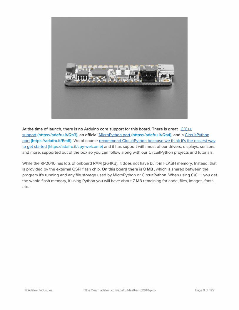
At the time of launch, there is no Arduino core support for this board. There is great C/C++
support (https://adafru.it/Qa3), an official MicroPython port (https://adafru.it/Qa4), and a CircuitPython
port (https://adafru.it/Em8)! We of course recommend CircuitPython because we think it's the easiest way
to get started (https://adafru.it/cpy-welcome) and it has support with most of our drivers, displays, sensors,
and more, supported out of the box so you can follow along with our CircuitPython projects and tutorials.
While the RP2040 has lots of onboard RAM (264KB), it does not have built-in FLASH memory. Instead, that
is provided by the external QSPI flash chip. On this board there is 8 MB , which is shared between the
program it's running and any file storage used by MicroPython or CircuitPython. When using C/C++ you get
the whole flash memory, if using Python you will have about 7 MB remaining for code, files, images, fonts,
etc.
© Adafruit Industries https://learn.adafruit.com/adafruit-feather-rp2040-pico Page 9 of 122

RP2040 Chip features:
Dual ARM Cortex-M0+ @ 133MHz
264kB on-chip SRAM in six independent banks
Support for up to 16MB of off-chip Flash memory via dedicated QSPI bus
DMA controller
Fully-connected AHB crossbar
Interpolator and integer divider peripherals
On-chip programmable LDO to generate core voltage
2 on-chip PLLs to generate USB and core clocks
30 GPIO pins, 4 of which can be used as analog inputs
Peripherals
2 UARTs
2 SPI controllers
2 I2C controllers
16 PWM channels
USB 1.1 controller and PHY, with host and device support
8 PIO state machines
© Adafruit Industries https://learn.adafruit.com/adafruit-feather-rp2040-pico Page 10 of 122

Comes fully assembled and tested, with the UF2 USB bootloader. We also toss in some header, so you
can solder it in and plug it into a solderless breadboard.
© Adafruit Industries https://learn.adafruit.com/adafruit-feather-rp2040-pico Page 11 of 122

Pinouts
The Feather RP2040 has many pins, ports and features. This page takes you on a tour of the board!
Pinout diagram courtesy of Bill Binko at ATMakers.
© Adafruit Industries https://learn.adafruit.com/adafruit-feather-rp2040-pico Page 12 of 122

Power Pins and Connections
USB C connector - This is used for power and data. Connect to your computer via a USB C cable to
update firmware and edit code.
LiPoly Battery connector - This 2-pin JST PH connector allows you to plug in lipoly batteries to power
the Feather. The Feather is also capable of charging batteries plugged into this port via USB.
GND - This is the common ground for all power and logic.
BAT - This is the positive voltage to/from the 2-pin JST jack for the optional Lipoly battery.
USB - This is the positive voltage to/from the USB C jack, if USB is connected.
EN - This is the 3.3V regulator's enable pin. It's pulled up, so connect to ground to disable the 3.3V
regulator.
3.3V - These pins are the output from the 3.3V regulator, they can supply 500mA peak.
© Adafruit Industries https://learn.adafruit.com/adafruit-feather-rp2040-pico Page 13 of 122
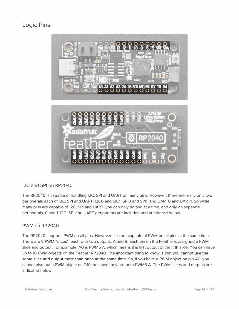
Logic Pins
I2C and SPI on RP2040
The RP2040 is capable of handling I2C, SPI and UART on many pins. However, there are really only two
peripherals each of I2C, SPI and UART: I2C0 and I2C1, SPI0 and SPI1, and UART0 and UART1. So while
many pins are capable of I2C, SPI and UART, you can only do two at a time, and only on separate
peripherals, 0 and 1. I2C, SPI and UART peripherals are included and numbered below.
PWM on RP2040
The RP2040 supports PWM on all pins. However, it is not capable of PWM on all pins at the same time.
There are 8 PWM "slices", each with two outputs, A and B. Each pin on the Feather is assigned a PWM
slice and output. For example, A0 is PWM5 A, which means it is first output of the fifth slice. You can have
up to 16 PWM objects on the Feather RP2040. The important thing to know is that you cannot use the
same slice and output more than once at the same time. So, if you have a PWM object on pin A0, you
cannot also put a PWM object on D10, because they are both PWM5 A. The PWM slices and outputs are
indicated below.
© Adafruit Industries https://learn.adafruit.com/adafruit-feather-rp2040-pico Page 14 of 122

Analog Pins
The RP2040 has four ADCs. These pins are the only pins capable of handling analog, and they can also
do digital.
A0/GP26 - This pin is ADC0. It is also SPI1 SCK, I2C1 SDA and PWM5 A.
A1/GP27 - This pin is ADC1. It is also SPI1 MOSI, I2C1 SCL and PWM5 B.
A2/GP28 - This pin is ADC2. It is also SPI1 MISO, I2C1 SDA and PWM6 A.
A3/GP29 - This pin is ADC3. It is also SPI1 CS, I2C0 SCL and PWM6 B.
Digital Pins
These are the digital I/O pins. They all have multiple capabilities.
D24/GP24 - Digital I/O pin 24. It is also UART1 TX, I2C0 SDA, and PWM4 A.
D25/GP25 - Digital I/O pin 25. It is also UART1 RX, I2C0 SCL, and PWM4 B.
SCK/GP18 - The main SPI0 SCK. It is also I2C1 SDA and PWM1 A.
MO/GP19 - The main SPI0 MOSI. It is also I2C1 SCL and PWM1 B.
MI/GP20 - The main SPI0 MISO. It is also UART1 TX, I2C0 SDA and PWM2 A.
RX/GP01 - The main UART0 RX pin. It is also I2C0 SDA, SPI0 CS and PWM0 B.
TX/GP00 - The main UART0 TX pin. It is also I2C0 SCL, SPI0 MISO and PWM0 A.
D4/GP06 - Digital I/O pin 4. It is also SPI0 SCK, I2C1 SDA and PWM3 A.
D13/GP13 - Digital I/O pin 13. It is also SPI1 CS, UART0 RX, I2C0 SCL and PWM6 B.
D12/GP12 - Digital I/O pin 12. It is also SPI1 MISO, UART0 TX, I2C0 SDA and PWM6 A.
D11/GP11 - Digital I/O pin 11. It is also SPI1 MOSI, I2C1 SCL and PWM5 B.
D10/GP10 - Digital I/O pin 10. It is also SPI1 SCK, I2C1 SDA and PWM5 A.
D9/GP09 - Digital I/O pin 9. It is also SPI1 CS, UART1 RX, I2C0 SCL and PWM4 B.
D6/GP08 - Digital I/O pin 6. It is also SPI1 MISO, UART1 TX, I2C0 SDA and PWM4 A.
D5/GP07 - Digital I/O pin 5. It is also SPI0 MOSI, I2C1 SCL and PWM3 B.
SCL/GP03 - The main I2C1 clock pin. It is also SPI0 MOSI, I2C1 SCL and PWM1 B.
SDA/GP02 - The main I2C1 data pin. It is also SPI0 SCK, I2C1 SDA and PWM1 A.
CircuitPython Pins vs GPxx Pins
There are pin labels on both sides of the Feather RP2040. Which should you use? In CircuitPython, use
the pin labels on the top of the board (such as A0, D4, SCL, RX, etc.). If you're looking to work with this
board and the RP2040 SDK, use the pin labels on the bottom of the board (GP00 and GP01, etc.).
CircuitPython I2C, SPI and UART
Note that in CircuitPython, there is a board object each for I2C, SPI and UART that use the pins labeled on
the Feather. You can use these objects to initialise these peripherals in your code.
board.I2C() uses SCL/SDA
© Adafruit Industries https://learn.adafruit.com/adafruit-feather-rp2040-pico Page 15 of 122

board.SPI() uses SCK/MO/MI
board.UART() uses RX/TX
GPIO Pins by Pin Functionality
Primary pins based on Feather RP2040 silk are bold.
I2C Pins
I2C0 SCL: A3, D25, RX, D13, D9
I2C0 SDA: A2, D24, MISO, TX, D12, D6
I2C1 SCL: SCL, A1, MOSI, D11, D5
I2C1 SDA: SDA, A0, SCK, D4, D10
SPI Pins
SPI0 SCK: SCK, D4, SDA
SPI0 MOSI: MOSI, D5, SCL
SPI0 MISO: MISO, TX
SPI0 CS: RX
SPI1 SCK: A0, D10
SPI1 MOSI: A1, D11
SPI1 MISO: A2, D24, D12, D6
SPI1 CS: A3, D25, D13, D9
UART Pins
UART0 TX: TX, A2, D12
UART0 RX: RX, A3, D13
UART1 TX: D24, MISO, D6
UART1 RX: D25, D9
PWM Pins
PWM0 A: TX
PWM0 B: RX
PWM1 A: SCK, SDA
PWM1 B: MOSI, SCL
PWM2 A: MISO
PWM2 B: (none)
PWM3 A: D4
PWM3 B: D5
PWM4 A: D24, D6
© Adafruit Industries https://learn.adafruit.com/adafruit-feather-rp2040-pico Page 16 of 122

PWM4 B: D25, D9
PWM5 A: A0, D10
PWM5 B: A1, D11
PWM6 A: A2, D12
PWM6 B: A3, D13
Microcontroller and Flash
The square towards the middle is the RP2040 microcontroller, the "brains" of the Feather RP2040 board.
The square near the BOOTSEL button is the QSPI Flash. It is connected to 6 pins that are not brought out
on the GPIO pads. This way you don't have to worry about the SPI flash colliding with other devices on the
main SPI connection.
QSPI is neat because it allows you to have 4 data in/out lines instead of just SPI's single line in and single
line out. This means that QSPI is at least 4 times faster. But in reality is at least 10x faster because you can
clock the QSPI peripheral much faster than a plain SPI peripheral
Buttons and RST Pin
© Adafruit Industries https://learn.adafruit.com/adafruit-feather-rp2040-pico Page 17 of 122

The Feather RP2040 has two buttons.
The BOOTSEL button is used to enter the bootloader. To enter the bootloader, press and hold BOOTSEL
and then power up the board (either by plugging it into USB or pressing RESET). The bootloader is used to
install/update CircuitPython.
The RESET button restarts the board and helps enter the bootloader. You can click it to reset the board
without unplugging the USB cable or battery.
The RST pin is can be used to reset the board. Tie to ground manually to reset the board.
LEDs
Above the pin labels for A0 and A1 is the status NeoPixel LED. In CircuitPython, the NeoPixel is
board.NEOPIXEL and the library for it is here (https://adafru.it/wby) and in the bundle (https://adafru.it/ENC)
The NeoPixel is powered by the 3.3V power supply but that hasn't shown to make a big difference in
brightness or color. In CircuitPython, the LED is used to indicate the runtime status.
Below the USB C connector is the CHG LED. This indicates the charge status of a connected lipoly battery,
© Adafruit Industries https://learn.adafruit.com/adafruit-feather-rp2040-pico Page 18 of 122

if one is present and USB is connected. It is amber while charging, and green when fully charged. Note,
it's normal for this LED to flicker when no battery is in place, that's the charge circuitry trying to detect
whether a battery is there or not.
Above the USB C connector is the D13 LED. This little red LED is controllable in CircuitPython code using
board.LED . Also, this LED will pulse when the board is in bootloader mode.
STEMMA QT
The Feather RP2040 comes with a built in STEMMA QT connector ! This means you can connect up all
sorts of I2C sensors and breakouts (https://adafru.it/GfR), no soldering required! This connector uses the
SCL and SDA pins for I2C meaning it is peripheral I2C1.
STEMMA QT / Qwiic JST SH 4-pin Cable - 100mm LongThis 4-wire cable is a little over 100mm / 4" long and fitted with JST-SH female 4-pin connectors on both ends. Compared with the
chunkier JST-PH these are 1mm pitch instead of...
$0.95In Stock
Debug Interfaces
Add to Cart
© Adafruit Industries https://learn.adafruit.com/adafruit-feather-rp2040-pico Page 19 of 122

For advanced debugging or to reprogram your Feather RP2040, there is a footprint to solder a 2*5 pin
0.05" standard SWD header on the board. The image above shows the "pin 1" location by marking it with a
triangle. This orientation places the connector key facing towards the end of the board where the USB
connector is. This allows you to use something like a Segger J-Link (https://adafru.it/yDp) and a 1.27mm
SWD cable (https://adafru.it/wbA) to connect from your PC to the Feather.
© Adafruit Industries https://learn.adafruit.com/adafruit-feather-rp2040-pico Page 20 of 122

On the back of the board are pads for the SWCLK and SWDIO pins. They provide access to the internal
Serial Wire Debug multi-drop bus, which provides debug access to both processors, and can be used to
download code.
Mini SWD 0.05" Pitch Connector - 10 Pin SMT Box HeaderWe've carrying a new 1.27mm pitch 2x5 Mini SWD 0.05" Pitch Connector. It's a tinier, bite-sized version of the
$1.95In Stock
SWD 0.05" Pitch Connector - 10 Pin SMT Box HeaderThis 1.27mm pitch, 2x5 male SMT Box Header is the same one used on our SWD Cable Breakout Board. The header...
$1.50In Stock
Add to Cart
Add to Cart
© Adafruit Industries https://learn.adafruit.com/adafruit-feather-rp2040-pico Page 21 of 122

Assembly
We ship Feathers fully tested but without headers attached - this gives you the most flexibility on choosing
how to use and configure your Feather
Header Options!Before you go gung-ho on soldering, there's a few options to consider!
The first option is soldering in plain male headers, this lets
you plug in the Feather into a solderless breadboard
© Adafruit Industries https://learn.adafruit.com/adafruit-feather-rp2040-pico Page 22 of 122

Another option is to go with socket female headers. This
won't let you plug the Feather into a breadboard but it will
let you attach featherwings very easily
© Adafruit Industries https://learn.adafruit.com/adafruit-feather-rp2040-pico Page 23 of 122

We also have 'slim' versions of the female headers, that
are a little shorter and give a more compact shape
© Adafruit Industries https://learn.adafruit.com/adafruit-feather-rp2040-pico Page 24 of 122

Finally, there's the "Stacking Header" option. This one is
sort of the best-of-both-worlds. You get the ability to plug
into a solderless breadboard and plug a featherwing on
top. But its a little bulky
Soldering in Plain Headers
Prepare the header strip:Cut the strip to length if necessary. It will be easier to
solder if you insert it into a breadboard - long pins down
© Adafruit Industries https://learn.adafruit.com/adafruit-feather-rp2040-pico Page 25 of 122

Add the breakout board:Place the breakout board over the pins so that the short
pins poke through the breakout pads
And Solder!Be sure to solder all pins for reliable electrical contact.
(For tips on soldering, be sure to check out our Guide to
Excellent Soldering (https://adafru.it/aTk)).
© Adafruit Industries https://learn.adafruit.com/adafruit-feather-rp2040-pico Page 26 of 122

Solder the other strip as well.
© Adafruit Industries https://learn.adafruit.com/adafruit-feather-rp2040-pico Page 27 of 122

You're done! Check your solder joints visually and
continue onto the next steps
Soldering on Female Header
Tape In PlaceFor sockets you'll want to tape them in place so when you
flip over the board they don't fall out
© Adafruit Industries https://learn.adafruit.com/adafruit-feather-rp2040-pico Page 28 of 122

Flip & Tack SolderAfter flipping over, solder one or two points on each strip,
to 'tack' the header in place
© Adafruit Industries https://learn.adafruit.com/adafruit-feather-rp2040-pico Page 29 of 122

And Solder!Be sure to solder all pins for reliable electrical contact.
(For tips on soldering, be sure to check out our Guide to
Excellent Soldering (https://adafru.it/aTk)).
© Adafruit Industries https://learn.adafruit.com/adafruit-feather-rp2040-pico Page 30 of 122

You're done! Check your solder joints visually and
continue onto the next steps
© Adafruit Industries https://learn.adafruit.com/adafruit-feather-rp2040-pico Page 31 of 122

Power Management
Battery + USB PowerWe wanted to make the Feather easy to power both when connected to a computer as well as via battery.
There's two ways to power a Feather. You can connect with a USB cable C (just plug into the jack) and the
Feather will regulate the 5V USB down to 3.3V. You can also connect a 4.2/3.7V Lithium Polymer
(Lipo/Lipoly) or Lithium Ion (LiIon) battery to the JST jack. This will let the Feather run on a rechargable
battery. When the USB power is powered, it will automatically switch over to USB for power, as well as
start charging the battery (if attached) at 200mA. This happens 'hotswap' style so you can always keep
the Lipoly connected as a 'backup' power that will only get used when USB power is lost.
The JST connector polarity is matched to Adafruit LiPoly batteries. Using wrong polarity batteries
can destroy your Feather�
© Adafruit Industries https://learn.adafruit.com/adafruit-feather-rp2040-pico Page 32 of 122
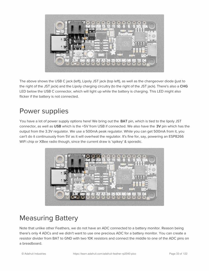
The above shows the USB C jack (left), Lipoly JST jack (top left), as well as the changeover diode (just to
the right of the JST jack) and the Lipoly charging circuitry (to the right of the JST jack). There's also a CHG
LED below the USB C connector, which will light up while the battery is charging. This LED might also
flicker if the battery is not connected.
Power suppliesYou have a lot of power supply options here! We bring out the BAT pin, which is tied to the lipoly JST
connector, as well as USB which is the +5V from USB if connected. We also have the 3V pin which has the
output from the 3.3V regulator. We use a 500mA peak regulator. While you can get 500mA from it, you
can't do it continuously from 5V as it will overheat the regulator. It's fine for, say, powering an ESP8266
WiFi chip or XBee radio though, since the current draw is 'spikey' & sporadic.
Measuring BatteryNote that unlike other Feathers, we do not have an ADC connected to a battery monitor. Reason being
there's only 4 ADCs and we didn't want to use one precious ADC for a battery monitor. You can create a
resistor divider from BAT to GND with two 10K resistors and connect the middle to one of the ADC pins on
a breadboard.
© Adafruit Industries https://learn.adafruit.com/adafruit-feather-rp2040-pico Page 33 of 122

ENable pinIf you'd like to turn off the 3.3V regulator, you can do that with the EN(able) pin. Simply tie this pin to
Ground and it will disable the 3V regulator. The BAT and USB pins will still be powered
Alternative Power OptionsThe two primary ways for powering a feather are a 3.7/4.2V LiPo battery plugged into the JST port or aUSB power cable.
If you need other ways to power the Feather, here's what we recommend:
For permanent installations, a 5V 1A USB wall adapter (https://adafru.it/duP) will let you plug in a USB
cable for reliable power
For mobile use, where you don't want a LiPoly, use a USB battery pack! (https://adafru.it/e2q)
If you have a higher voltage power supply, use a 5V buck converter (https://adafru.it/DHs) and wire it
to a USB cable's 5V and GND input (https://adafru.it/DHu)
Here's what you cannot do:
Do not use alkaline or NiMH batteries and connect to the battery port - this will destroy the LiPoly
charger and there's no way to disable the charger
Do not use 7.4V RC batteries on the battery port - this will destroy the board
The Feather is not designed for external power supplies - this is a design decision to make the board
compact and low cost. It is not recommended, but technically possible:
Connect an external 3.3V power supply to the 3V and GND pins. Not recommended, this may cause
unexpected behavior and the EN pin will no longer. Also this doesn't provide power on BAT or USB
and some Feathers/Wings use those pins for high current usages. You may end up damaging your
Feather.
© Adafruit Industries https://learn.adafruit.com/adafruit-feather-rp2040-pico Page 34 of 122

Connect an external 5V power supply to the USB and GND pins. Not recommended, this may cause
unexpected behavior when plugging in the USB port because you will be back-powering the USB
port, which could confuse or damage your computer.
© Adafruit Industries https://learn.adafruit.com/adafruit-feather-rp2040-pico Page 35 of 122

Install CircuitPython
CircuitPython (https://adafru.it/tB7) is a derivative of MicroPython (https://adafru.it/BeZ) designed to simplify
experimentation and education on low-cost microcontrollers. It makes it easier than ever to get
prototyping by requiring no upfront desktop software downloads. Simply copy and edit files on the
CIRCUITPY drive to iterate.
CircuitPython Quickstart
Follow this step-by-step to quickly get CircuitPython running on your board.
https://adafru.it/R1D
Click the link above to download the latest CircuitPython
UF2 file.
Save it wherever is convenient for you.
To enter the bootloader, hold down the BOOT/BOOTSEL button (highlighted in red above), and while
continuing to hold it (don't let go!), press and release the reset button (highlighted in blue above).
Continue to hold the BOOT/BOOTSEL button until the RPI-RP2 drive appears!
If the drive does not appear, release all the buttons, and then repeat the process above.
https://adafru.it/R1D
© Adafruit Industries https://learn.adafruit.com/adafruit-feather-rp2040-pico Page 36 of 122

You can also start with your board unplugged from USB, press and hold the BOOTSEL button (highlighted
in red above), continue to hold it while plugging it into USB, and wait for the drive to appear before
releasing the button.
A lot of people end up using charge-only USB cables and it is very frustrating! Make sure you have a USB
cable you know is good for data sync.
You will see a new disk drive appear called RPI-RP2.
Drag the adafruit_circuitpython_etc.uf2 file to RPI-RP2.
The RPI-RP2 drive will disappear and a new disk drive
called CIRCUITPY will appear.
That's it, you're done! :)
Safe Mode
You want to edit your code.py or modify the files on your CIRCUITPY drive, but find that you can't.
© Adafruit Industries https://learn.adafruit.com/adafruit-feather-rp2040-pico Page 37 of 122

Perhaps your board has gotten into a state where CIRCUITPY is read-only. You may have turned off the
CIRCUITPY drive altogether. Whatever the reason, safe mode can help.
Safe mode in CircuitPython does not run any user code on startup, and disables auto-reload. This means a
few things. First, safe mode bypasses any code in boot.py (where you can set CIRCUITPY read-only or
turn it off completely). Second, it does not run the code in code.py. And finally, it does not automaticallysoft-reload when data is written to the CIRCUITPY drive.
Therefore, whatever you may have done to put your board in a non-interactive state, safe mode gives you
the opportunity to correct it without losing all of the data on the CIRCUITPY drive.
Entering Safe Mode in CircuitPython 6.x
To enter safe mode when using CircuitPython 6.x, plug in your board or hit reset (highlighted in red
above). Immediately after the board starts up or resets, it waits 700ms. On some boards, the onboard
status LED (highlighted in green above) will turn solid yellow during this time. If you press reset during that
700ms, the board will start up in safe mode. It can be difficult to react to the yellow LED, so you may want
to think of it simply as a slow double click of the reset button. (Remember, a fast double click of reset
enters the bootloader.)
Entering Safe Mode in CircuitPython 7.x
To enter safe mode when using CircuitPython 7.x, plug in your board or hit reset (highlighted in red
above). Immediately after the board starts up or resets, it waits 1000ms. On some boards, the onboard
This section explains entering safe mode on CircuitPython 6.x.�
This section explains entering safe mode on CircuitPython 7.x.�
© Adafruit Industries https://learn.adafruit.com/adafruit-feather-rp2040-pico Page 38 of 122

status LED (highlighted in green above) will blink yellow during that time. If you press reset during that
1000ms, the board will start up in safe mode. It can be difficult to react to the yellow LED, so you may want
to think of it simply as a slow double click of the reset button. (Remember, a fast double click of reset
enters the bootloader.)
In Safe Mode
Once you've entered safe mode successfully in CircuitPython 6.x, the LED will pulse yellow.
If you successfully enter safe mode on CircuitPython 7.x, the LED will intermittently blink yellow three
times.
If you connect to the serial console, you'll find the following message.
Auto-reload is off.Running in safe mode! Not running saved code.
CircuitPython is in safe mode because you pressed the reset button during boot. Press again to exit safe mode.
Press any key to enter the REPL. Use CTRL-D to reload.
You can now edit the contents of the CIRCUITPY drive. Remember, your code will not run until you pressthe reset button, or unplug and plug in your board, to get out of safe mode.
Flash Resetting UF2
If your board ever gets into a really weird state and doesn't even show up as a disk drive when installing
CircuitPython, try loading this 'nuke' UF2 which will do a 'deep clean' on your Flash Memory. You will lose
all the files on the board, but at least you'll be able to revive it! After loading this UF2, follow the steps
above to re-install CircuitPython.
https://adafru.it/RLE
https://adafru.it/RLE
© Adafruit Industries https://learn.adafruit.com/adafruit-feather-rp2040-pico Page 39 of 122

Installing Mu Editor
Mu is a simple code editor that works with the Adafruit CircuitPython boards. It's written in Python and
works on Windows, MacOS, Linux and Raspberry Pi. The serial console is built right in so you get
immediate feedback from your board's serial output!
Download and Install Mu
Download Mu
from https://codewith.mu (https://adafru.it/Be6). Click
the Download or Start Here links there for downloads and
installation instructions. The website has a wealth of other
information, including extensive tutorials and and how-
to's.
Using Mu
The first time you start Mu, you will be prompted to select
your 'mode' - you can always change your mind later. For
now please select CircuitPython!
The current mode is displayed in the lower right corner of
the window, next to the "gear" icon. If the mode says
"Microbit" or something else, click the Mode button in the
upper left, and then choose "CircuitPython" in the dialog
box that appears.
Mu is our recommended editor - please use it (unless you are an experienced coder with a
favorite editor already!)�
© Adafruit Industries https://learn.adafruit.com/adafruit-feather-rp2040-pico Page 40 of 122

Mu attempts to auto-detect your board, so please plug in
your CircuitPython device and make sure it shows up as
a CIRCUITPY drive before starting Mu
You can now explore Mu! The three main sections of the window are labeled below; the button bar, the
text editor, and the serial console / REPL.
Now you're ready to code! Let's keep going...
© Adafruit Industries https://learn.adafruit.com/adafruit-feather-rp2040-pico Page 41 of 122
Creating and Editing Code
One of the best things about CircuitPython is how simple it is to get code up and running. In this section,
we're going to cover how to create and edit your first CircuitPython program.
To create and edit code, all you'll need is an editor. There are many options. We strongly recommend
using Mu! It's designed for CircuitPython, and it's really simple and easy to use, with a built in serial
console!
If you don't or can't use Mu, there are basic text editors built into every operating system such as Notepad
on Windows, TextEdit on Mac, and gedit on Linux. However, many of these editors don't write back
changes immediately to files that you edit. That can cause problems when using CircuitPython. See the
Editing Code (https://adafru.it/id3) section below. If you want to skip that section for now, make sure you
do "Eject" or "Safe Remove" on Windows or "sync" on Linux after writing a file if you aren't using Mu. (This
is not a problem on MacOS.)
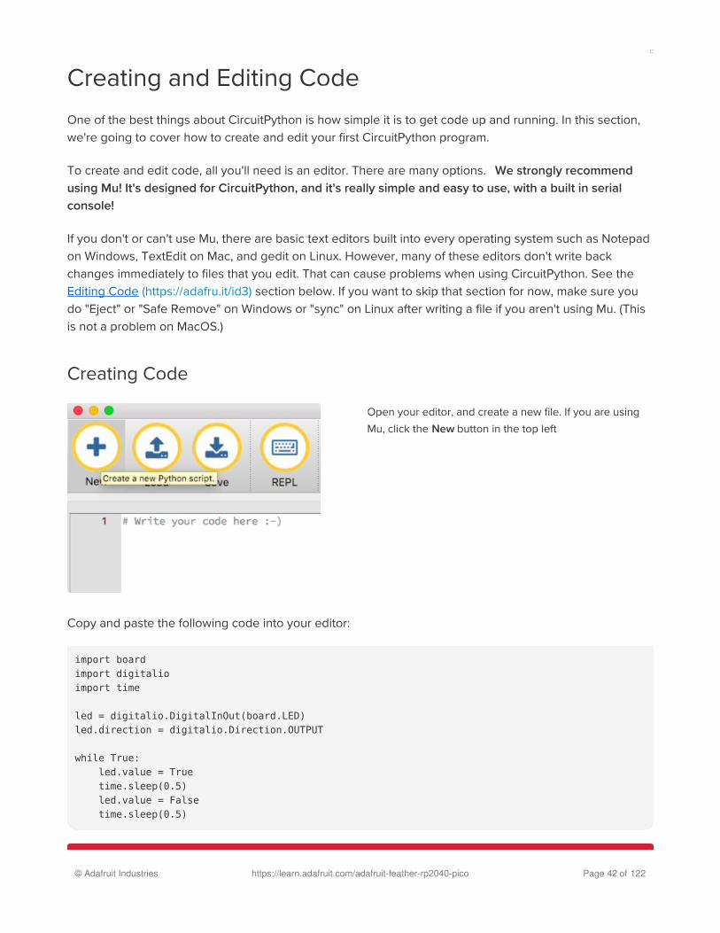
Creating Code
Open your editor, and create a new file. If you are using
Mu, click the New button in the top left
Copy and paste the following code into your editor:
import boardimport digitalioimport time
led = digitalio.DigitalInOut(board.LED)led.direction = digitalio.Direction.OUTPUT
while True: led.value = True time.sleep(0.5) led.value = False time.sleep(0.5)
© Adafruit Industries https://learn.adafruit.com/adafruit-feather-rp2040-pico Page 42 of 122

If you're using QT Py or a Trinkey, please download the NeoPixel blink example (https://adafru.it/SB2).
For Adafruit CLUE, you'll need to use board.D17 instead of board.LED . The rest of the code remains the
same. Make the following change to the led = line:
led = digitalio.DigitalInOut(board.D17)
For Adafruit ItsyBitsy nRF52840, you'll need to use board.BLUE_LED instead of board.LED . The rest of the
code remains the same. Make the following change to the led = line:
led = digitalio.DigitalInOut(board.BLUE_LED)
It will look like this - note that under the while True: line,
the next four lines have spaces to indent them, but they're
indented exactly the same amount. All other lines have no
spaces before the text.
The QT Py and the Trinkeys do not have a built-in little red LED! There is an addressable RGB
NeoPixel LED. The above example will NOT work on the QT Py or the Trinkeys!�
The NeoPixel blink example uses the onboard NeoPixel, but the time code is the same. You can
use the linked NeoPixel Blink example to follow along with this guide page.�
If you are using Adafruit CLUE, you will need to edit the code to use board.D17 as shown below!�
If you are using Adafruit ItsyBitsy nRF52840, you will need to edit the code to use
board.BLUE_LED as shown below!�
© Adafruit Industries https://learn.adafruit.com/adafruit-feather-rp2040-pico Page 43 of 122

Save this file as code.py on your CIRCUITPY drive.
On each board (except the ItsyBitsy nRF52840) you'll find a tiny red LED. On the ItsyBitsy nRF52840, you'll
find a tiny blue LED.
The little LED should now be blinking. Once per second.
Congratulations, you've just run your first CircuitPython program!
Editing Code
To edit code, open the code.py file on your CIRCUITPY
drive into your editor.
Make the desired changes to your code. Save the file.
That's it!
© Adafruit Industries https://learn.adafruit.com/adafruit-feather-rp2040-pico Page 44 of 122

Your code changes are run as soon as the file is done saving.
There's just one warning we have to give you before we continue...
The CircuitPython code on your board detects when the files are changed or written and will automatically
re-start your code. This makes coding very fast because you save, and it re-runs.
However, you must wait until the file is done being saved before unplugging or resetting your board! On
Windows using some editors this can sometimes take up to 90 seconds, on Linux it can take 30 seconds
to complete because the text editor does not save the file completely. Mac OS does not seem to have this
delay, which is nice!
This is really important to be aware of. If you unplug or reset the board before your computer finishes
writing the file to your board, you can corrupt the drive. If this happens, you may lose the code you've
written, so it's important to backup your code to your computer regularly.
There are a few ways to avoid this:
1. Use an editor that writes out the file completely when you save it.
Recommended editors:
mu (https://adafru.it/Be6) is an editor that safely writes all changes (it's also our recommended editor!)
emacs (https://adafru.it/xNA) is also an editor that will fulIy write files on save (https://adafru.it/Be7)
Sublime Text (https://adafru.it/xNB) safely writes all changes
Visual Studio Code (https://adafru.it/Be9) appears to safely write all changes
gedit on Linux appears to safely write all changes
IDLE (https://adafru.it/IWB), in Python 3.8.1 or later, was fixed (https://adafru.it/IWD) to write all changes
immediately
thonny (https://adafru.it/Qb6) fully writes files on save
Recommended only with particular settings or with add-ons:
vim (https://adafru.it/ek9) / vi safely writes all changes. But set up vim to not write
swapfiles (https://adafru.it/ELO) (.swp files: temporary records of your edits) to CIRCUITPY. Run vim
with vim -n , set the no swapfile option, or set the directory option to write swapfiles elsewhere.
Otherwise the swapfile writes trigger restarts of your program.
The PyCharm IDE (https://adafru.it/xNC) is safe if "Safe Write" is turned on in Settings->System
Settings->Synchronization (true by default).
If you are using Atom (https://adafru.it/fMG), install the fsync-on-save
package (https://adafru.it/E9m) so that it will always write out all changes to files on CIRCUITPY .
Don't Click Reset or Unplug!�
© Adafruit Industries https://learn.adafruit.com/adafruit-feather-rp2040-pico Page 45 of 122

�
SlickEdit (https://adafru.it/DdP) works only if you add a macro to flush the disk (https://adafru.it/ven).
We don't recommend these editors:
notepad (the default Windows editor) and Notepad++ can be slow to write, so we recommend the
editors above! If you are using notepad, be sure to eject the drive (see below)
IDLE in Python 3.8.0 or earlier does not force out changes immediately
nano (on Linux) does not force out changes
geany (on Linux) does not force out changes
Anything else - we haven't tested other editors so please use a recommended one!
2. Eject or Sync the Drive After Writing
If you are using one of our not-recommended-editors, not all is lost! You can still make it work.
On Windows, you can Eject or Safe Remove the CIRCUITPY drive. It won't actually eject, but it will force
the operating system to save your file to disk. On Linux, use the sync command in a terminal to force the
write to disk.
You also need to do this if you use Windows Explorer or a Linux graphical file manager to drag a file onto
CIRCUITPY
Oh No I Did Something Wrong and Now The CIRCUITPY DriveDoesn't Show Up!!!Don't worry! Corrupting the drive isn't the end of the world (or your board!). If this happens, follow the
steps found on the Troubleshooting (https://adafru.it/Den) page of every board guide to get your board
up and running again.
If you are dragging a file from your host computer onto the CIRCUITPY drive, you still need to do
step 2. Eject or Sync (below) to make sure the file is completely written.�
© Adafruit Industries https://learn.adafruit.com/adafruit-feather-rp2040-pico Page 46 of 122

Back to Editing Code...Now! Let's try editing the program you added to your board. Open your code.py file into your editor. We'll
make a simple change. Change the first 0.5 to 0.1 . The code should look like this:
import boardimport digitalioimport time
led = digitalio.DigitalInOut(board.LED)led.direction = digitalio.Direction.OUTPUT
while True: led.value = True time.sleep(0.1) led.value = False time.sleep(0.5)
© Adafruit Industries https://learn.adafruit.com/adafruit-feather-rp2040-pico Page 47 of 122

Leave the rest of the code as-is. Save your file. See what happens to the LED on your board? Something
changed! Do you know why? Let's find out!
Exploring Your First CircuitPython ProgramFirst, we'll take a look at the code we're editing.
Here is the original code again:
import boardimport digitalioimport time
led = digitalio.DigitalInOut(board.LED)led.direction = digitalio.Direction.OUTPUT
while True: led.value = True time.sleep(0.5) led.value = False time.sleep(0.5)
Imports & Libraries
Each CircuitPython program you run needs to have a lot of information to work. The reason CircuitPython
is so simple to use is that most of that information is stored in other files and works in the background. The
files built into CircuitPython are called modules, and the files you load separately are called libraries.
Modules are built into CircuitPython. Libraries are stored on your CIRCUITPY drive in a folder called lib.
import boardimport digitalioimport time
The import statements tells the board that you're going to use a particular library in your code. In this
example, we imported three modules: board , digitalio , and time . All three of these modules are built into
CircuitPython, so no separate library files are needed. That's one of the things that makes this an excellent
first example. You don't need any thing extra to make it work! board gives you access to the hardware on
your board, digitalio lets you access that hardware as inputs/outputs and time let's you pass time by
'sleeping'
Setting Up The LED
The next two lines setup the code to use the LED.
© Adafruit Industries https://learn.adafruit.com/adafruit-feather-rp2040-pico Page 48 of 122

led = digitalio.DigitalInOut(board.LED)led.direction = digitalio.Direction.OUTPUT
Your board knows the red LED as LED . So, we initialise that pin, and we set it to output. We set led to
equal the rest of that information so we don't have to type it all out again later in our code.
Loop-de-loops
The third section starts with a while statement. while True: essentially means, "forever do the following:".
while True: creates a loop. Code will loop "while" the condition is "true" (vs. false), and as True is never
False, the code will loop forever. All code that is indented under while True: is "inside" the loop.
Inside our loop, we have four items:
while True: led.value = True time.sleep(0.5) led.value = False time.sleep(0.5)
First, we have led.value = True . This line tells the LED to turn on. On the next line, we have time.sleep(0.5) .
This line is telling CircuitPython to pause running code for 0.5 seconds. Since this is between turning the
led on and off, the led will be on for 0.5 seconds.
The next two lines are similar. led.value = False tells the LED to turn off, and time.sleep(0.5) tells
CircuitPython to pause for another 0.5 seconds. This occurs between turning the led off and back on so
the LED will be off for 0.5 seconds too.
Then the loop will begin again, and continue to do so as long as the code is running!
So, when you changed the first 0.5 to 0.1 , you decreased the amount of time that the code leaves the
LED on. So it blinks on really quickly before turning off!
Great job! You've edited code in a CircuitPython program!
What Happens When My Code Finishes Running?
When your code finishes running, CircuitPython resets your microcontroller board to prepare it for the
next run of code. That means any set up you did earlier no longer applies, and the pin states are reset.
For example, try reducing the above example to led.value = True . The LED will flash almost too quickly to
see, and turn off. This is because the code finishes running and resets the pin state, and the LED is no
longer receiving a signal.
© Adafruit Industries https://learn.adafruit.com/adafruit-feather-rp2040-pico Page 49 of 122

�
To that end, most CircuitPython programs involve some kind of loop, infinite or otherwise
What if I don't have the loop?If you don't have the loop, the code will run to the end and exit. This can lead to some unexpected
behavior in simple programs like this since the "exit" also resets the state of the hardware. This is a
different behavior than running commands via REPL. So if you are writing a simple program that doesn't
seem to work, you may need to add a loop to the end so the program doesn't exit.
The simplest loop would be:
while True:
pass
And remember - you can press to exit the loop.
See also the Behavior section in the docs (https://adafru.it/Bvz).
© Adafruit Industries https://learn.adafruit.com/adafruit-feather-rp2040-pico Page 50 of 122

More ChangesWe don't have to stop there! Let's keep going. Change the second 0.5 to 0.1 so it looks like this:
while True: led.value = True time.sleep(0.1) led.value = False time.sleep(0.1)
Now it blinks really fast! You decreased the both time that the code leaves the LED on and off!
Now try increasing both of the 0.1 to 1 . Your LED will blink much more slowly because you've increased
the amount of time that the LED is turned on and off.
Well done! You're doing great! You're ready to start into new examples and edit them to see what
happens! These were simple changes, but major changes are done using the same process. Make your
desired change, save it, and get the results. That's really all there is to it!
Naming Your Program File
CircuitPython looks for a code file on the board to run. There are four options: code.txt, code.py, main.txt
and main.py. CircuitPython looks for those files, in that order, and then runs the first one it finds. While we
suggest using code.py as your code file, it is important to know that the other options exist. If your
program doesn't seem to be updating as you work, make sure you haven't created another code file that's
being read instead of the one you're working on.
© Adafruit Industries https://learn.adafruit.com/adafruit-feather-rp2040-pico Page 51 of 122

Connecting to the Serial Console
One of the staples of CircuitPython (and programming in general!) is something called a "print statement".
This is a line you include in your code that causes your code to output text. A print statement in
CircuitPython looks like this:
print("Hello, world!")
This line would result in:
Hello, world!
However, these print statements need somewhere to display. That's where the serial console comes in!
The serial console receives output from your CircuitPython board sent over USB and displays it so you can
see it. This is necessary when you've included a print statement in your code and you'd like to see what
you printed. It is also helpful for troubleshooting errors, because your board will send errors and the serial
console will print those too.
The serial console requires a terminal program. A terminal is a program that gives you a text-based
interface to perform various tasks.
sudo apt purge modemmanager
Are you using Mu?If so, good news! The serial console is built into Mu and will autodetect your board making using the
REPL really really easy.
Please note that Mu does yet not work with nRF52 or ESP8266-based CircuitPython boards, skip down to
the next section for details on using a terminal program.
If you're on Linux, and are seeing multi-second delays connecting to the serial console, or are
seeing "AT" and other gibberish when you connect, then the modemmanager service might be
interfering. Just remove it; it doesn't have much use unless you're still using dial-up modems. To
remove, type this command at a shell:
�
© Adafruit Industries https://learn.adafruit.com/adafruit-feather-rp2040-pico Page 52 of 122
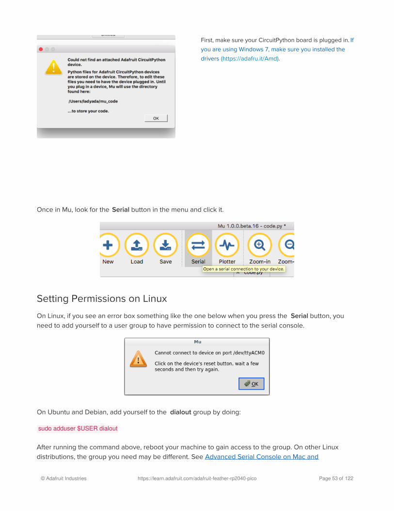
First, make sure your CircuitPython board is plugged in. If
you are using Windows 7, make sure you installed the
drivers (https://adafru.it/Amd).
Once in Mu, look for the Serial button in the menu and click it.
Setting Permissions on Linux
On Linux, if you see an error box something like the one below when you press the Serial button, you
need to add yourself to a user group to have permission to connect to the serial console.
On Ubuntu and Debian, add yourself to the dialout group by doing:
sudo adduser $USER dialout
After running the command above, reboot your machine to gain access to the group. On other Linux
distributions, the group you need may be different. See Advanced Serial Console on Mac and
© Adafruit Industries https://learn.adafruit.com/adafruit-feather-rp2040-pico Page 53 of 122

Linux (https://adafru.it/AAI) for details on how to add yourself to the right group.
Using Something Else?If you're not using Mu to edit, are using ESP8266 or nRF52 CircuitPython, or if for some reason you are
not a fan of the built in serial console, you can run the serial console as a separate program.
Windows requires you to download a terminal program, check out this page for more
details (https://adafru.it/AAH)
Mac and Linux both have one built in, though other options are available for download, check this page for
more details (https://adafru.it/AAI)
© Adafruit Industries https://learn.adafruit.com/adafruit-feather-rp2040-pico Page 54 of 122

Interacting with the Serial Console
Once you've successfully connected to the serial console, it's time to start using it.
The code you wrote earlier has no output to the serial console. So, we're going to edit it to create some
output.
Open your code.py file into your editor, and include a print statement. You can print anything you like!
Just include your phrase between the quotation marks inside the parentheses. For example:
import boardimport digitalioimport time
led = digitalio.DigitalInOut(board.LED)led.direction = digitalio.Direction.OUTPUT
while True: print("Hello, CircuitPython!") led.value = True time.sleep(1) led.value = False time.sleep(1)
Save your file.
Now, let's go take a look at the window with our connection to the serial console.
Excellent! Our print statement is showing up in our console! Try changing the printed text to something
else.
© Adafruit Industries https://learn.adafruit.com/adafruit-feather-rp2040-pico Page 55 of 122

Keep your serial console window where you can see it. Save your file. You'll see what the serial console
displays when the board reboots. Then you'll see your new change!
The Traceback (most recent call last): is telling you the last thing your board was doing before you saved
your file. This is normal behavior and will happen every time the board resets. This is really handy for
troubleshooting. Let's introduce an error so we can see how it is used.
Delete the e at the end of True from the line led.value = True so that it says led.value = Tru
Save your file. You will notice that your red LED will stop blinking, and you may have a colored status LED
blinking at you. This is because the code is no longer correct and can no longer run properly. We need to
fix it!
© Adafruit Industries https://learn.adafruit.com/adafruit-feather-rp2040-pico Page 56 of 122

Usually when you run into errors, it's not because you introduced them on purpose. You may have 200
lines of code, and have no idea where your error could be hiding. This is where the serial console can
help. Let's take a look!
The Traceback (most recent call last): is telling you that the last thing it was able to run was line 10 in your
code. The next line is your error: NameError: name 'Tru' is not defined . This error might not mean a lot to
you, but combined with knowing the issue is on line 10, it gives you a great place to start!
Go back to your code, and take a look at line 10. Obviously, you know what the problem is already. But if
you didn't, you'd want to look at line 10 and see if you could figure it out. If you're still unsure, try googling
the error to get some help. In this case, you know what to look for. You spelled True wrong. Fix the typo
and save your file.
Nice job fixing the error! Your serial console is streaming and your red LED Is blinking again.
The serial console will display any output generated by your code. Some sensors, such as a humidity
© Adafruit Industries https://learn.adafruit.com/adafruit-feather-rp2040-pico Page 57 of 122

sensor or a thermistor, receive data and you can use print statements to display that information. You can
also use print statements for troubleshooting. If your code isn't working, and you want to know where it's
failing, you can put print statements in various places to see where it stops printing.
The serial console has many uses, and is an amazing tool overall for learning and programming!
© Adafruit Industries https://learn.adafruit.com/adafruit-feather-rp2040-pico Page 58 of 122

The REPL
The other feature of the serial connection is the Read-Evaluate-Print-Loop, or REPL. The REPL allows you
to enter individual lines of code and have them run immediately. It's really handy if you're running into
trouble with a particular program and can't figure out why. It's interactive so it's great for testing new ideas.
To use the REPL, you first need to be connected to the serial console. Once that connection has been
established, you'll want to press Ctrl + C.
If there is code running, it will stop and you'll see Press any key to enter the REPL. Use CTRL-D to reload.Follow those instructions, and press any key on your keyboard.
The Traceback (most recent call last): is telling you the last thing your board was doing before you pressed
Ctrl + C and interrupted it. The KeyboardInterrupt is you pressing Ctrl + C. This information can be handy
when troubleshooting, but for now, don't worry about it. Just note that it is expected behavior.
If there is no code running, you will enter the REPL immediately after pressing Ctrl + C. There is no
information about what your board was doing before you interrupted it because there is no code running.
Either way, once you press a key you'll see a >>> prompt welcoming you to the REPL!
© Adafruit Industries https://learn.adafruit.com/adafruit-feather-rp2040-pico Page 59 of 122

If you have trouble getting to the >>> prompt, try pressing Ctrl + C a few more times.
The first thing you get from the REPL is information about your board.
This line tells you the version of CircuitPython you're using and when it was released. Next, it gives you
the type of board you're using and the type of microcontroller the board uses. Each part of this may be
different for your board depending on the versions you're working with.
This is followed by the CircuitPython prompt.
From this prompt you can run all sorts of commands and code. The first thing we'll do is run help() . This
will tell us where to start exploring the REPL. To run code in the REPL, type it in next to the REPL prompt.
Type help() next to the prompt in the REPL.
Then press enter. You should then see a message.
© Adafruit Industries https://learn.adafruit.com/adafruit-feather-rp2040-pico Page 60 of 122

First part of the message is another reference to the version of CircuitPython you're using. Second, a URL
for the CircuitPython related project guides. Then... wait. What's this? To list built-in modules, please do`help("modules")`. Remember the libraries you learned about while going through creating code? That's
exactly what this is talking about! This is a perfect place to start. Let's take a look!
Type help("modules") into the REPL next to the prompt, and press enter.
This is a list of all the core libraries built into CircuitPython. We discussed how board contains all of the
pins on the board that you can use in your code. From the REPL, you are able to see that list!
Type import board into the REPL and press enter. It'll go to a new prompt. It might look like nothing
happened, but that's not the case! If you recall, the import statement simply tells the code to expect to do
something with that module. In this case, it's telling the REPL that you plan to do something with that
module.
Next, type dir(board) into the REPL and press enter.
This is a list of all of the pins on your board that are available for you to use in your code. Each board's list
will differ slightly depending on the number of pins available. Do you see LED ? That's the pin you used to
blink the red LED!
The REPL can also be used to run code. Be aware that any code you enter into the REPL isn't saved
© Adafruit Industries https://learn.adafruit.com/adafruit-feather-rp2040-pico Page 61 of 122

anywhere. If you're testing something new that you'd like to keep, make sure you have it saved
somewhere on your computer as well!
Every programmer in every programming language starts with a piece of code that says, "Hello, World."
We're going to say hello to something else. Type into the REPL:
print("Hello, CircuitPython!")
Then press enter.
That's all there is to running code in the REPL! Nice job!
You can write single lines of code that run stand-alone. You can also write entire programs into the REPL
to test them. As we said though, remember that nothing typed into the REPL is saved.
There's a lot the REPL can do for you. It's great for testing new ideas if you want to see if a few new lines
of code will work. It's fantastic for troubleshooting code by entering it one line at a time and finding out
where it fails. It lets you see what libraries are available and explore those libraries.
Try typing more into the REPL to see what happens!
Returning to the serial consoleWhen you're ready to leave the REPL and return to the serial console, simply press Ctrl + D . This will
reload your board and reenter the serial console. You will restart the program you had running before
entering the REPL. In the console window, you'll see any output from the program you had running. And if
your program was affecting anything visual on the board, you'll see that start up again as well.
You can return to the REPL at any time!
© Adafruit Industries https://learn.adafruit.com/adafruit-feather-rp2040-pico Page 62 of 122

CircuitPython Pins and Modules
CircuitPython is designed to run on microcontrollers and allows you to interface with all kinds of sensors,
inputs and other hardware peripherals. There are tons of guides showing how to wire up a circuit, and use
CircuitPython to, for example, read data from a sensor, or detect a button press. Most CircuitPython code
includes hardware setup which requires various modules, such as board or digitalio . You import these
modules and then use them in your code. How does CircuitPython know to look for hardware in the
specific place you connected it, and where do these modules come from?
This page explains both. You'll learn how CircuitPython finds the pins on your microcontroller board,
including how to find the available pins for your board and what each pin is named. You'll also learn about
the modules built into CircuitPython, including how to find all the modules available for your board.
CircuitPython PinsWhen using hardware peripherals with a CircuitPython compatible microcontroller, you'll almost certainly
be utilising pins. This section will cover how to access your board's pins using CircuitPython, how to
discover what pins and board-specific objects are available in CircuitPython for your board, how to use the
board-specific objects, and how to determine all available pin names for a given pin on your board.
import board
When you're using any kind of hardware peripherals wired up to your microcontroller board, the import list
in your code will include import board . The board module is built into CircuitPython, and is used to provide
access to a series of board-specific objects, including pins. Take a look at your microcontroller board.
You'll notice that next to the pins are pin labels. You can always access a pin by its pin label. However,
there are almost always multiple names for a given pin.
To see all the available board-specific objects and pins for your board, enter the REPL ( >>> ) and run the
following commands:
import boarddir(board)
Here is the output for the QT Py.
The following pins have labels on the physical QT Py board: A0, A1, A2, A3, SDA, SCL, TX, RX, SCK, MISO,
and MOSI. You see that there are many more entries available in board than the labels on the QT Py.
© Adafruit Industries https://learn.adafruit.com/adafruit-feather-rp2040-pico Page 63 of 122

You can use the pin names on the physical board, regardless of whether they seem to be specific to a
certain protocol.
For example, you do not have to use the SDA pin for I2C - you can use it for a button or LED.
On the flip side, there may be multiple names for one pin. For example, on the QT Py, pin A0 is labeled on
the physical board silkscreen, but it is available in CircuitPython as both A0 and D0 . For more information
on finding all the names for a given pin, see the What Are All the Available Pin
Names? (https://adafru.it/QkA) section below.
The results of dir(board) for CircuitPython compatible boards will look similar to the results for the QT Py in
terms of the pin names, e.g. A0, D0, etc. However, some boards, for example, the Metro ESP32-S2, have
different styled pin names. Here is the output for the Metro ESP32-S2.
Note that most of the pins are named in an IO# style, such as IO1 and IO2. Those pins on the physical
board are labeled only with a number, so an easy way to know how to access them in CircuitPython, is to
run those commands in the REPL and find the pin naming scheme.
I2C, SPI, and UART
You'll also see there are often (but not always!) three special board-specific objects included: I2C , SPI ,
and UART - each one is for the default pin-set used for each of the three common protocol busses they
are named for. These are called singletons.
What's a singleton? When you create an object in CircuitPython, you are instantiating ('creating') it.
Instantiating an object means you are creating an instance of the object with the unique values that are
provided, or "passed", to it.
For example, When you instantiate an I2C object using the busio module, it expects two pins: clock and
data, typically SCL and SDA. It often looks like this:
i2c = busio.I2C(board.SCL, board.SDA)
If your code is failing to run because it can't find a pin name you provided, verify that you have the
proper pin name by running these commands in the REPL.�
© Adafruit Industries https://learn.adafruit.com/adafruit-feather-rp2040-pico Page 64 of 122

Then, you pass the I2C object to a driver for the hardware you're using. For example, if you were using the
TSL2591 light sensor and its CircuitPython library, the next line of code would be:
tsl2591 = adafruit_tsl2591.TSL2591(i2c)
However, CircuitPython makes this simpler by including the I2C singleton in the board module. Instead of
the two lines of code above, you simply provide the singleton as the I2C object. So if you were using the
TSL2591 and its CircuitPython library, the two above lines of code would be replaced with:
tsl2591 = adafruit_tsl2591.TSL2591(board.I2C())
This eliminates the need for the busio module, and simplifies the code. Behind the scenes, the
board.I2C() object is instantiated when you call it, but not before, and on subsequent calls, it returns the
same object. Basically, it does not create an object until you need it, and provides the same object every
time you need it. You can call board.I2C() as many times as you like, and it will always return the same
object.
What Are All the Available Names?
Many pins on CircuitPython compatible microcontroller boards have multiple names, however, typically,
there's only one name labeled on the physical board. So how do you find out what the other available pin
names are? Simple, with the following script! Each line printed out to the serial console contains the set of
names for a particular pin.
On a microcontroller board running CircuitPython, connect to the serial console. Then, save the following
as code.py on your CIRCUITPY drive.
The UART/SPI/I2C singletons will use the 'default' bus pins for each board - often labeled as
RX/TX (UART), MOSI/MISO/SCK (SPI), or SDA/SCL (I2C). Check your board documentation/pinout
for the default busses.�
© Adafruit Industries https://learn.adafruit.com/adafruit-feather-rp2040-pico Page 65 of 122

"""CircuitPython Essentials Pin Map Script"""import microcontrollerimport board
board_pins = []for pin in dir(microcontroller.pin): if isinstance(getattr(microcontroller.pin, pin), microcontroller.Pin): pins = [] for alias in dir(board): if getattr(board, alias) is getattr(microcontroller.pin, pin): pins.append("board.{}".format(alias)) if len(pins) > 0: board_pins.append(" ".join(pins))for pins in sorted(board_pins): print(pins)
Here is the result when this script is run on QT Py:
Each line represents a single pin. Find the line containing the pin name that's labeled on the physical
board, and you'll find the other names available for that pin. For example, the first pin on the board is
labeled A0. The first line in the output is board.A0 board.D0 . This means that you can access pin A0 with
both board.A0 and board.D0 .
You'll notice there are two "pins" that aren't labeled on the board but appear in the list: board.NEOPIXELand board.NEOPIXEL_POWER . Many boards have several of these special pins that give you access to
built-in board hardware, such as an LED or an on-board sensor. The Qt Py only has one on-board extra
piece of hardware, a NeoPixel LED, so there's only the one available in the list. But you can also control
whether or not power is applied to the NeoPixel, so there's a separate pin for that.
That's all there is to figuring out the available names for a pin on a compatible microcontroller board in
CircuitPython!
Microcontroller Pin Names
The pin names available to you in the CircuitPython board module are not the same as the names of the
pins on the microcontroller itself. The board pin names are aliases to the microcontroller pin names. If you
© Adafruit Industries https://learn.adafruit.com/adafruit-feather-rp2040-pico Page 66 of 122

look at the datasheet for your microcontroller, you'll likely find a pinout with a series of pin names, such as
"PA18" or "GPIO5". If you want to get to the actual microcontroller pin name in CircuitPython, you'll need
the microcontroller.pin module. As with board , you can run dir(microcontroller.pin) in the REPL to receive a
list of the microcontroller pin names.
CircuitPython Built-In ModulesThere is a set of modules used in most CircuitPython programs. One or more of these modules is always
used in projects involving hardware. Often hardware requires installing a separate library from the Adafruit
CircuitPython Bundle. But, if you try to find board or digitalio in the same bundle, you'll come up lacking.
So, where do these modules come from? They're built into CircuitPython! You can find an comprehensive
list of built-in CircuitPython modules and the technical details of their functionality from CircuitPython
here (https://adafru.it/QkB) and the Python-like modules included here (https://adafru.it/QkC). However, not
every module is available for every board due to size constraints or hardware limitations. How do you find
out what modules are available for your board?
There are two options for this. You can check the support matrix (https://adafru.it/N2a), and search for your
board by name. Or, you can use the REPL.
Plug in your board, connect to the serial console and enter the REPL. Type the following command.
help("modules")
That's it! You now know two ways to find all of the modules built into CircuitPython for your compatible
microcontroller board.
© Adafruit Industries https://learn.adafruit.com/adafruit-feather-rp2040-pico Page 67 of 122

CircuitPython Libraries
Each CircuitPython program you run needs to have a lot of information to work. The reason CircuitPython
is so simple to use is that most of that information is stored in other files and works in the background.
These files are called libraries. Some of them are built into CircuitPython. Others are stored on your
CIRCUITPY drive in a folder called lib. Part of what makes CircuitPython so awesome is its ability to store
code separately from the firmware itself. Storing code separately from the firmware makes it easier to
update both the code you write and the libraries you depend.
Your board may ship with a lib folder already, it's in the base directory of the drive. If not, simply create the
folder yourself. When you first install CircuitPython, an empty lib directory will be created for you.
CircuitPython libraries work in the same way as regular Python modules so the Python
docs (https://adafru.it/rar) are a great reference for how it all should work. In Python terms, we can place
our library files in the lib directory because its part of the Python path by default.
One downside of this approach of separate libraries is that they are not built in. To use them, one needs to
copy them to the CIRCUITPY drive before they can be used. Fortunately, we provide a bundle full of our
As we continue to develop CircuitPython and create new releases, we will stop supporting older
releases. Visit https://circuitpython.org/downloads to download the latest version of CircuitPython
for your board. You must download the CircuitPython Library Bundle that matches your version of
CircuitPython. Please update CircuitPython and then visit https://circuitpython.org/libraries to
download the latest Library Bundle.
�
© Adafruit Industries https://learn.adafruit.com/adafruit-feather-rp2040-pico Page 68 of 122

libraries.
Our bundle and releases also feature optimized versions of the libraries with the .mpy file extension.
These files take less space on the drive and have a smaller memory footprint as they are loaded.
Installing the CircuitPython Library Bundle
We're constantly updating and improving our libraries, so we don't (at this time) ship our CircuitPython
boards with the full library bundle. Instead, you can find example code in the guides for your board that
depends on external libraries. Some of these libraries may be available from us at Adafruit, some may be
written by community members!
Either way, as you start to explore CircuitPython, you'll want to know how to get libraries on board.
You can grab the latest Adafruit CircuitPython Bundle release by clicking the button below.
Note: Match up the bundle version with the version of CircuitPython you are running - 3.x library for
running any version of CircuitPython 3, 4.x for running any version of CircuitPython 4, etc. If you mix
libraries with major CircuitPython versions, you will most likely get errors due to changes in library
interfaces possible during major version changes.
https://adafru.it/ENC
If you need another version, you can also visit the bundle release page (https://adafru.it/Ayy) which will let
you select exactly what version you're looking for, as well as information about changes.
Either way, download the version that matches your CircuitPython firmware version. If you don't know
the version, look at the initial prompt in the CircuitPython REPL, which reports the version. For example, if
you're running v4.0.1, download the 4.x library bundle. There's also a py bundle which contains the
uncompressed python files, you probably don't want that unless you are doing advanced work on
libraries.
After downloading the zip, extract its contents. This is usually done by double clicking on the zip. On Mac
OSX, it places the file in the same directory as the zip.
https://adafru.it/ENC
© Adafruit Industries https://learn.adafruit.com/adafruit-feather-rp2040-pico Page 69 of 122

Open the bundle folder. Inside you'll find two information files, and two folders. One folder is the lib
bundle, and the other folder is the examples bundle.
Now open the lib folder. When you open the folder, you'll see a large number of mpy files and folders
Example Files
All example files from each library are now included in the bundles, as well as an examples-only bundle.
These are included for two main reasons:
Allow for quick testing of devices.
Provide an example base of code, that is easily built upon for individualized purposes.
© Adafruit Industries https://learn.adafruit.com/adafruit-feather-rp2040-pico Page 70 of 122

Copying Libraries to Your BoardFirst you'll want to create a lib folder on your CIRCUITPY drive. Open the drive, right click, choose the
option to create a new folder, and call it lib. Then, open the lib folder you extracted from the downloaded
zip. Inside you'll find a number of folders and .mpy files. Find the library you'd like to use, and copy it to the
lib folder on CIRCUITPY.
This also applies to example files. They are only supplied as raw .py files, so they may need to be
converted to .mpy using the mpy-cross utility if you encounter MemoryErrors . This is discussed in the
CircuitPython Essentials Guide (https://adafru.it/CTw). Usage is the same as described above in the
Express Boards section. Note: If you do not place examples in a separate folder, you would remove the
examples from the import statement.
Example: ImportError Due to Missing Library
If you choose to load libraries as you need them, you may write up code that tries to use a library you
haven't yet loaded. We're going to demonstrate what happens when you try to utilise a library that you
don't have loaded on your board, and cover the steps required to resolve the issue.
This demonstration will only return an error if you do not have the required library loaded into the lib
folder on your CIRCUITPY drive.
Let's use a modified version of the blinky example.
If a library has multiple .mpy files contained in a folder, be sure to copy the entire folder to
CIRCUITPY/lib.�
© Adafruit Industries https://learn.adafruit.com/adafruit-feather-rp2040-pico Page 71 of 122

import boardimport timeimport simpleio
led = simpleio.DigitalOut(board.D13)
while True: led.value = True time.sleep(0.5) led.value = False time.sleep(0.5)
Save this file. Nothing happens to your board. Let's check the serial console to see what's going on.
We have an ImportError . It says there is no module named 'simpleio' . That's the one we just included in our
code!
Click the link above to download the correct bundle. Extract the lib folder from the downloaded bundle file.
Scroll down to find simpleio.mpy. This is the library file we're looking for! Follow the steps above to load
an individual library file.
The LED starts blinking again! Let's check the serial console.
No errors! Excellent. You've successfully resolved an ImportError !
If you run into this error in the future, follow along with the steps above and choose the library that
matches the one you're missing.
© Adafruit Industries https://learn.adafruit.com/adafruit-feather-rp2040-pico Page 72 of 122

Library Install on Non-Express Boards
If you have a Trinket M0 or Gemma M0, you'll want to follow the same steps in the example above to
install libraries as you need them. You don't always need to wait for an ImportError as you probably know
what library you added to your code. Simply open the lib folder you downloaded, find the library you need,
and drag it to the lib folder on your CIRCUITPY drive.
You may end up running out of space on your Trinket M0 or Gemma M0 even if you only load libraries as
you need them. There are a number of steps you can use to try to resolve this issue. You'll find them in the
Troubleshooting page in the Learn guides for your board.
Updating CircuitPython Libraries/Examples
Libraries and examples are updated from time to time, and it's important to update the files you have on
your CIRCUITPY drive.
To update a single library or example, follow the same steps above. When you drag the library file to your
lib folder, it will ask if you want to replace it. Say yes. That's it!
A new library bundle is released every time there's an update to a library. Updates include things like bug
fixes and new features. It's important to check in every so often to see if the libraries you're using have
been updated.
© Adafruit Industries https://learn.adafruit.com/adafruit-feather-rp2040-pico Page 73 of 122

�
Frequently Asked Questions
These are some of the common questions regarding CircuitPython and CircuitPython microcontrollers.
I have to continue using an older version of CircuitPython; where can Ifind compatible libraries?
We are no longer building or supporting library bundles for older versions of CircuitPython. We highly
encourage you to update CircuitPython to the latest version (https://adafru.it/Em8) and use the current
version of the libraries (https://adafru.it/ENC). However, if for some reason you cannot update, here are
points to the last available library bundles for previous versions:
2.x (https://adafru.it/FJA)
3.x (https://adafru.it/FJB)
4.x (https://adafru.it/QDL)
5.x (https://adafru.it/QDJ)
Is ESP8266 or ESP32 supported in CircuitPython? Why not?We dropped ESP8266 support as of 4.x - For more information please read about it here!
https://learn.adafruit.com/welcome-to-circuitpython/circuitpython-for-esp8266 (https://adafru.it/CiG)
We do not support ESP32 because it does not have native USB. We do support ESP32-S2, which does.
As we continue to develop CircuitPython and create new releases, we will stop supporting older
releases. Visit https://circuitpython.org/downloads to download the latest version of CircuitPython
for your board. You must download the CircuitPython Library Bundle that matches your version of
CircuitPython. Please update CircuitPython and then visit https://circuitpython.org/libraries to
download the latest Library Bundle.
�
© Adafruit Industries https://learn.adafruit.com/adafruit-feather-rp2040-pico Page 74 of 122

� How do I connect to the Internet with CircuitPython?If you'd like to add WiFi support, check out our guide on ESP32/ESP8266 as a co-
processor. (https://adafru.it/Dwa)
© Adafruit Industries https://learn.adafruit.com/adafruit-feather-rp2040-pico Page 75 of 122

� Is there asyncio support in CircuitPython?We do not have asyncio support in CircuitPython at this time. However, async and await are turned on
in many builds, and we are looking at how to use event loops and other constructs effectively and
easily.
© Adafruit Industries https://learn.adafruit.com/adafruit-feather-rp2040-pico Page 76 of 122

� My RGB NeoPixel/DotStar LED is blinking funny colors - what does itmean?The status LED can tell you what's going on with your CircuitPython board. Read more here for what the
colors mean! (https://adafru.it/Den)
© Adafruit Industries https://learn.adafruit.com/adafruit-feather-rp2040-pico Page 77 of 122

What is a MemoryError ?
Memory allocation errors happen when you're trying to store too much on the board. The CircuitPython
microcontroller boards have a limited amount of memory available. You can have about 250 lines of code
on the M0 Express boards. If you try to import too many libraries, a combination of large libraries, or run a
program with too many lines of code, your code will fail to run and you will receive a MemoryError in the
serial console (REPL).
What do I do when I encounter a MemoryError ?
© Adafruit Industries https://learn.adafruit.com/adafruit-feather-rp2040-pico Page 78 of 122

Try resetting your board. Each time you reset the board, it reallocates the memory. While this is unlikely to
resolve your issue, it's a simple step and is worth trying.
Make sure you are using .mpy versions of libraries. All of the CircuitPython libraries are available in the
bundle in a .mpy format which takes up less memory than .py format. Be sure that you're using the latest
library bundle (https://adafru.it/uap) for your version of CircuitPython.
If that does not resolve your issue, try shortening your code. Shorten comments, remove extraneous or
unneeded code, or any other clean up you can do to shorten your code. If you're using a lot of functions,
you could try moving those into a separate library, creating a .mpy of that library, and importing it into
your code.
You can turn your entire file into a .mpy and import that into code.py . This means you will be unable to
edit your code live on the board, but it can save you space.
Can the order of my import statements affect memory?
It can because the memory gets fragmented differently depending on allocation order and the size of
objects. Loading .mpy files uses less memory so its recommended to do that for files you aren't editing.
How can I create my own .mpy files?
You can make your own .mpy versions of files with mpy-cross .
You can download mpy-cross for your operating system from https://adafruit-circuit-
python.s3.amazonaws.com/index.html?prefix=bin/mpy-cross/ (https://adafru.it/QDK). Almost any version
will do. The format for .mpy files has not changed since CircuitPython 4.x.
To make a .mpy file, run ./mpy-cross path/to/yourfile.py to create a yourfile.mpy in the same directory as the
original file.
How do I check how much memory I have free?import gcgc.mem_free()
Will give you the number of bytes available for use.
Does CircuitPython support interrupts?
No. CircuitPython does not currently support interrupts. We do not have an estimated time for when they
will be included.
© Adafruit Industries https://learn.adafruit.com/adafruit-feather-rp2040-pico Page 79 of 122

Does Feather M0 support WINC1500?
No, WINC1500 will not fit into the M0 flash space.
Can AVRs such as ATmega328 or ATmega2560 run CircuitPython?
No.
Commonly Used Acronyms
CP or CPy = CircuitPython (https://adafru.it/cpy-welcome)
CPC = Circuit Playground Classic (https://adafru.it/ncE)
CPX = Circuit Playground Express (https://adafru.it/wpF)
© Adafruit Industries https://learn.adafruit.com/adafruit-feather-rp2040-pico Page 80 of 122

Welcome to the Community!
CircuitPython is a programming language that's super simple to get started with and great for learning. It
runs on microcontrollers and works out of the box. You can plug it in and get started with any text editor.
The best part? CircuitPython comes with an amazing, supportive community.
Everyone is welcome! CircuitPython is Open Source. This means it's available for anyone to use, edit, copy
and improve upon. This also means CircuitPython becomes better because of you being a part of it. It
doesn't matter whether this is your first microcontroller board or you're a computer engineer, you have
something important to offer the Adafruit CircuitPython community. We're going to highlight some of the
many ways you can be a part of it!
Adafruit Discord
© Adafruit Industries https://learn.adafruit.com/adafruit-feather-rp2040-pico Page 81 of 122

The Adafruit Discord server is the best place to start. Discord is where the community comes together to
volunteer and provide live support of all kinds. From general discussion to detailed problem solving, and
everything in between, Discord is a digital maker space with makers from around the world.
There are many different channels so you can choose the one best suited to your needs. Each channel is
shown on Discord as "#channelname". There's the #help-with-projects channel for assistance with your
current project or help coming up with ideas for your next one. There's the #showandtell channel for
showing off your newest creation. Don't be afraid to ask a question in any channel! If you're unsure,
#general is a great place to start. If another channel is more likely to provide you with a better answer,
someone will guide you.
The help with CircuitPython channel is where to go with your CircuitPython questions. #help-with-
circuitpython is there for new users and developers alike so feel free to ask a question or post a comment!
Everyone of any experience level is welcome to join in on the conversation. We'd love to hear what you
have to say! The #circuitpython channel is available for development discussions as well.
The easiest way to contribute to the community is to assist others on Discord. Supporting others doesn't
always mean answering questions. Join in celebrating successes! Celebrate your mistakes! Sometimes
just hearing that someone else has gone through a similar struggle can be enough to keep a maker
moving forward.
The Adafruit Discord is the 24x7x365 hackerspace that you can bring your granddaughter to.
Visit https://adafru.it/discord ()to sign up for Discord. We're looking forward to meeting you!
Adafruit Forums
The Adafruit Forums (https://adafru.it/jIf) are the perfect place for support. Adafruit has wonderful paid
support folks to answer any questions you may have. Whether your hardware is giving you issues or your
code doesn't seem to be working, the forums are always there for you to ask. You need an Adafruit
account to post to the forums. You can use the same account you use to order from Adafruit.
While Discord may provide you with quicker responses than the forums, the forums are a more reliable
source of information. If you want to be certain you're getting an Adafruit-supported answer, the forums
are the best place to be.
© Adafruit Industries https://learn.adafruit.com/adafruit-feather-rp2040-pico Page 82 of 122

There are forum categories that cover all kinds of topics, including everything Adafruit. The Adafruit
CircuitPython and MicroPython (https://adafru.it/xXA) category under "Supported Products & Projects" is
the best place to post your CircuitPython questions.
Be sure to include the steps you took to get to where you are. If it involves wiring, post a picture! If your
code is giving you trouble, include your code in your post! These are great ways to make sure that there's
enough information to help you with your issue.
You might think you're just getting started, but you definitely know something that someone else doesn't.
The great thing about the forums is that you can help others too! Everyone is welcome and encouraged to
provide constructive feedback to any of the posted questions. This is an excellent way to contribute to the
community and share your knowledge!
Adafruit Github
Whether you're just beginning or are life-long programmer who would like to contribute, there are ways for
everyone to be a part of building CircuitPython. GitHub is the best source of ways to contribute to
CircuitPython (https://adafru.it/tB7) itself. If you need an account, visit https://github.com/
(https://adafru.it/d6C)and sign up.
If you're new to GitHub or programming in general, there are great opportunities for you. Head over to
adafruit/circuitpython (https://adafru.it/tB7) on GitHub, click on "Issues (https://adafru.it/Bee)", and you'll find
a list that includes issues labeled "good first issue (https://adafru.it/Bef)". These are things we've identified
as something that someone with any level of experience can help with. These issues include options like
updating documentation, providing feedback, and fixing simple bugs.
© Adafruit Industries https://learn.adafruit.com/adafruit-feather-rp2040-pico Page 83 of 122

Already experienced and looking for a challenge? Checkout the rest of the issues list and you'll find plenty
of ways to contribute. You'll find everything from new driver requests to core module updates. There's
plenty of opportunities for everyone at any level!
When working with CircuitPython, you may find problems. If you find a bug, that's great! We love bugs!
Posting a detailed issue to GitHub is an invaluable way to contribute to improving CircuitPython. Be sure to
include the steps to replicate the issue as well as any other information you think is relevant. The more
detail, the better!
Testing new software is easy and incredibly helpful. Simply load the newest version of CircuitPython or a
library onto your CircuitPython hardware, and use it. Let us know about any problems you find by posting
a new issue to GitHub. Software testing on both current and beta releases is a very important part of
contributing CircuitPython. We can't possibly find all the problems ourselves! We need your help to make
CircuitPython even better.
On GitHub, you can submit feature requests, provide feedback, report problems and much more. If you
have questions, remember that Discord and the Forums are both there for help!
ReadTheDocs
ReadTheDocs (https://adafru.it/Beg) is a an excellent resource for a more in depth look at CircuitPython.
This is where you'll find things like API documentation and details about core modules. There is also a
Design Guide that includes contribution guidelines for CircuitPython.
RTD gives you access to a low level look at CircuitPython. There are details about each of the core
modules (https://adafru.it/Beh). Each module lists the available libraries. Each module library page lists the
available parameters and an explanation for each. In many cases, you'll find quick code examples to help
you understand how the modules and parameters work, however it won't have detailed explanations like
© Adafruit Industries https://learn.adafruit.com/adafruit-feather-rp2040-pico Page 84 of 122

the Learn Guides. If you want help understanding what's going on behind the scenes in any CircuitPython
code you're writing, ReadTheDocs is there to help!
© Adafruit Industries https://learn.adafruit.com/adafruit-feather-rp2040-pico Page 85 of 122

Advanced Serial Console on Windows
Windows 7 DriverIf you're using Windows 7, use the link below to download the driver package. You will not need to install
drivers on Mac, Linux or Windows 10.
https://adafru.it/AB0
What's the COM?First, you'll want to find out which serial port your board is using. When you plug your board in to USB on
your computer, it connects to a serial port. The port is like a door through which your board can
communicate with your computer using USB.
We'll use Windows Device Manager to determine which port the board is using. The easiest way to
determine which port the board is using is to first check without the board plugged in. Open Device
Manager. Click on Ports (COM & LPT). You should find something already in that list with (COM#) after it
where # is a number.
Now plug in your board. The Device Manager list will refresh and a new item will appear under Ports (COM
& LPT). You'll find a different (COM#) after this item in the list.
https://adafru.it/AB0
© Adafruit Industries https://learn.adafruit.com/adafruit-feather-rp2040-pico Page 86 of 122
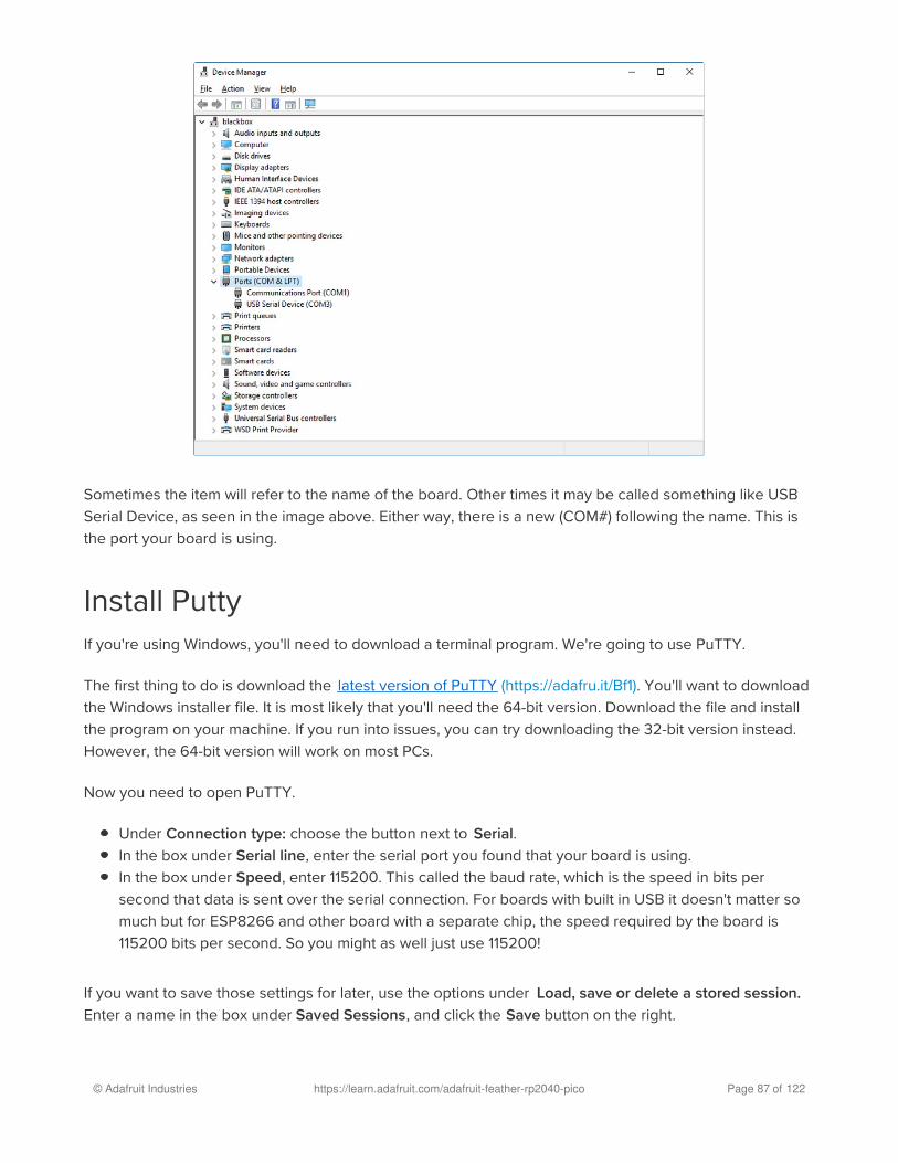
Sometimes the item will refer to the name of the board. Other times it may be called something like USB
Serial Device, as seen in the image above. Either way, there is a new (COM#) following the name. This is
the port your board is using.
Install PuttyIf you're using Windows, you'll need to download a terminal program. We're going to use PuTTY.
The first thing to do is download the latest version of PuTTY (https://adafru.it/Bf1). You'll want to download
the Windows installer file. It is most likely that you'll need the 64-bit version. Download the file and install
the program on your machine. If you run into issues, you can try downloading the 32-bit version instead.
However, the 64-bit version will work on most PCs.
Now you need to open PuTTY.
Under Connection type: choose the button next to Serial.
In the box under Serial line, enter the serial port you found that your board is using.
In the box under Speed, enter 115200. This called the baud rate, which is the speed in bits per
second that data is sent over the serial connection. For boards with built in USB it doesn't matter so
much but for ESP8266 and other board with a separate chip, the speed required by the board is
115200 bits per second. So you might as well just use 115200!
If you want to save those settings for later, use the options under Load, save or delete a stored session.
Enter a name in the box under Saved Sessions, and click the Save button on the right.
© Adafruit Industries https://learn.adafruit.com/adafruit-feather-rp2040-pico Page 87 of 122

Once your settings are entered, you're ready to connect to the serial console. Click "Open" at the bottom
of the window. A new window will open.
If no code is running, the window will either be blank or will look like the window above. Now you're ready
to see the results of your code.
Great job! You've connected to the serial console!
© Adafruit Industries https://learn.adafruit.com/adafruit-feather-rp2040-pico Page 88 of 122

Advanced Serial Console on Mac and Linux
Connecting to the serial console on Mac and Linux uses essentially the same process. Neither operating
system needs drivers installed. On MacOSX, Terminal comes installed. On Linux, there are a variety such
as gnome-terminal (called Terminal) or Konsole on KDE.
What's the Port?First you'll want to find out which serial port your board is using. When you plug your board in to USB on
your computer, it connects to a serial port. The port is like a door through which your board can
communicate with your computer using USB.
We're going to use Terminal to determine what port the board is using. The easiest way to determine
which port the board is using is to first check without the board plugged in. On Mac, open Terminal and
type the following:
ls /dev/tty.*
Each serial connection shows up in the /dev/ directory. It has a name that starts with tty. . The command
ls shows you a list of items in a directory. You can use * as a wildcard, to search for files that start with
the same letters but end in something different. In this case, we're asking to see all of the listings in /dev/that start with tty. and end in anything. This will show us the current serial connections.
For Linux, the procedure is the same, however, the name is slightly different. If you're using Linux, you'll
type:
ls /dev/ttyACM*
The concept is the same with Linux. We are asking to see the listings in the /dev/ folder, starting with
ttyACM and ending with anything. This will show you the current serial connections. In the example below,
© Adafruit Industries https://learn.adafruit.com/adafruit-feather-rp2040-pico Page 89 of 122

the error is indicating that are no current serial connections starting with ttyACM .
Now, plug your board. Using Mac, type:
ls /dev/tty.*
This will show you the current serial connections, which will now include your board.
Using Mac, a new listing has appeared called /dev/tty.usbmodem141441 . The tty.usbmodem141441 part of
this listing is the name the example board is using. Yours will be called something similar.
Using Linux, type:
ls /dev/ttyACM*
This will show you the current serial connections, which will now include your board.
© Adafruit Industries https://learn.adafruit.com/adafruit-feather-rp2040-pico Page 90 of 122

Using Linux, a new listing has appeared called /dev/ttyACM0 . The ttyACM0 part of this listing is the name
the example board is using. Yours will be called something similar.
Connect with screenNow that you know the name your board is using, you're ready connect to the serial console. We're going
to use a command called screen . The screen command is included with MacOS. Linux users may need to
install it using their package manager. To connect to the serial console, use Terminal. Type the following
command, replacing board_name with the name you found your board is using:
screen /dev/tty.board_name 115200
The first part of this establishes using the screen command. The second part tells screen the name of the
board you're trying to use. The third part tells screen what baud rate to use for the serial connection. The
baud rate is the speed in bits per second that data is sent over the serial connection. In this case, the
speed required by the board is 115200 bits per second.
© Adafruit Industries https://learn.adafruit.com/adafruit-feather-rp2040-pico Page 91 of 122

Press enter to run the command. It will open in the same window. If no code is running, the window will be
blank. Otherwise, you'll see the output of your code.
Great job! You've connected to the serial console!
Permissions on LinuxIf you try to run screen and it doesn't work, then you may be running into an issue with permissions. Linux
keeps track of users and groups and what they are allowed to do and not do, like access the hardware
associated with the serial connection for running screen . So if you see something like this:
then you may need to grant yourself access. There are generally two ways you can do this. The first is to
just run screen using the sudo command, which temporarily gives you elevated privileges.
Once you enter your password, you should be in:
© Adafruit Industries https://learn.adafruit.com/adafruit-feather-rp2040-pico Page 92 of 122

The second way is to add yourself to the group associated with the hardware. To figure out what that
group is, use the command ls -l as shown below. The group name is circled in red.
Then use the command adduser to add yourself to that group. You need elevated privileges to do this, so
you'll need to use sudo . In the example below, the group is adm and the user is ackbar.
After you add yourself to the group, you'll need to logout and log back in, or in some cases, reboot your
machine. After you log in again, verify that you have been added to the group using the command groups .
If you are still not in the group, reboot and check again.
And now you should be able to run screen without using sudo .
And you're in:
© Adafruit Industries https://learn.adafruit.com/adafruit-feather-rp2040-pico Page 93 of 122

The examples above use screen , but you can also use other programs, such as putty or picocom , if you
prefer.
© Adafruit Industries https://learn.adafruit.com/adafruit-feather-rp2040-pico Page 94 of 122

Troubleshooting
From time to time, you will run into issues when working with CircuitPython. Here are a few things you
may encounter and how to resolve them.
Always Run the Latest Version of CircuitPython andLibrariesAs we continue to develop CircuitPython and create new releases, we will stop supporting older releases.
You need to update to the latest CircuitPython. (https://adafru.it/Em8).
You need to download the CircuitPython Library Bundle that matches your version of CircuitPython.
Please update CircuitPython and then download the latest bundle (https://adafru.it/ENC).
As we release new versions of CircuitPython, we will stop providing the previous bundles as automatically
created downloads on the Adafruit CircuitPython Library Bundle repo. If you must continue to use an
earlier version, you can still download the appropriate version of mpy-cross from the particular release of
CircuitPython on the CircuitPython repo and create your own compatible .mpy library files. However, it is
best to update to the latest for both CircuitPython and the library bundle.
I have to continue using CircuitPython 5.x, 4.x, 3.x or2.x, where can I find compatible libraries?We are no longer building or supporting the CircuitPython 2.x, 3.x, 4.x or 5.x library bundles. We highly
encourage you to update CircuitPython to the latest version (https://adafru.it/Em8) and use the current
version of the libraries (https://adafru.it/ENC). However, if for some reason you cannot update, you can
find the last available 2.x build here (https://adafru.it/FJA), the last available 3.x build
here (https://adafru.it/FJB), the last available 4.x build here (https://adafru.it/QDL), and the last available 5.x
build here (https://adafru.it/QDJ).
CPLAYBOOT, TRINKETBOOT, FEATHERBOOT, orGEMMABOOT Drive Not Present
As we continue to develop CircuitPython and create new releases, we will stop supporting older
releases. Visit https://circuitpython.org/downloads to download the latest version of CircuitPython
for your board. You must download the CircuitPython Library Bundle that matches your version of
CircuitPython. Please update CircuitPython and then visit https://circuitpython.org/libraries to
download the latest Library Bundle.
�
© Adafruit Industries https://learn.adafruit.com/adafruit-feather-rp2040-pico Page 95 of 122

You may have a different board.
Only Adafruit Express boards and the Trinket M0 and Gemma M0 boards ship with the UF2 bootloader
(https://adafru.it/zbX)installed. Feather M0 Basic, Feather M0 Adalogger, and similar boards use a regular
Arduino-compatible bootloader, which does not show a boardnameBOOT drive.
MakeCode
If you are running a MakeCode (https://adafru.it/zbY) program on Circuit Playground Express, press the
reset button just once to get the CPLAYBOOT drive to show up. Pressing it twice will not work.
MacOS
DriveDx and its accompanything SAT SMART Driver can interfere with seeing the BOOT drive. See this
forum post (https://adafru.it/sTc) for how to fix the problem.
Windows 10
Did you install the Adafruit Windows Drivers package by mistake, or did you upgrade to Windows 10 with
the driver package installed? You don't need to install this package on Windows 10 for most Adafruit
boards. The old version (v1.5) can interfere with recognizing your device. Go to Settings -> Apps and
uninstall all the "Adafruit" driver programs.
Windows 7 or 8.1
Version 2.5.0.0 or later of the Adafruit Windows Drivers will fix the missing boardnameBOOT drive problem
on Windows 7 and 8.1. To resolve this, first uninstall the old versions of the drivers:
Unplug any boards. In Uninstall or Change a Program (Control Panel->Programs->Uninstall a
program), uninstall everything named "Windows Driver Package - Adafruit Industries LLC ...".
We recommend (https://adafru.it/Amd) that you upgrade to Windows 10 if possible; an upgrade is probably
still free for you: see the link.
© Adafruit Industries https://learn.adafruit.com/adafruit-feather-rp2040-pico Page 96 of 122

Now install the new 2.5.0.0 (or higher) Adafruit Windows Drivers Package:
https://adafru.it/AB0
When running the installer, you'll be shown a list of drivers to choose from. You can check and
uncheck the boxes to choose which drivers to install.
You should now be done! Test by unplugging and replugging the board. You should see the CIRCUITPYdrive, and when you double-click the reset button (single click on Circuit Playground Express running
MakeCode), you should see the appropriate boardnameBOOT drive.
Let us know in the Adafruit support forums (https://adafru.it/jIf) or on the Adafruit Discord () if this does not
work for you!
Windows Explorer Locks Up When AccessingboardnameBOOT DriveOn Windows, several third-party programs we know of can cause issues. The symptom is that you try to
access the boardnameBOOT drive, and Windows or Windows Explorer seems to lock up. These programs
are known to cause trouble:
AIDA64: to fix, stop the program. This problem has been reported to AIDA64. They acquired
hardware to test, and released a beta version that fixes the problem. This may have been
incorporated into the latest release. Please let us know in the forums if you test this.
Hard Disk Sentinel
Kaspersky anti-virus: To fix, you may need to disable Kaspersky completely. Disabling some aspects
of Kaspersky does not always solve the problem. This problem has been reported to Kaspersky.
ESET NOD32 anti-virus: We have seen problems with at least version 9.0.386.0, solved by
https://adafru.it/AB0
© Adafruit Industries https://learn.adafruit.com/adafruit-feather-rp2040-pico Page 97 of 122

uninstallation.
Copying UF2 to boardnameBOOT Drive Hangs at 0%CopiedOn Windows, a Western DIgital (WD) utility that comes with their external USB drives can interfere with
copying UF2 files to the boardnameBOOT drive. Uninstall that utility to fix the problem.
CIRCUITPY Drive Does Not AppearKaspersky anti-virus can block the appearance of the CIRCUITPY drive. We haven't yet figured out a
settings change that prevents this. Complete uninstallation of Kaspersky fixes the problem.
Norton anti-virus can interfere with CIRCUITPY . A user has reported this problem on Windows 7. The user
turned off both Smart Firewall and Auto Protect, and CIRCUITPY then appeared.
Windows 7 and 8.1 ProblemsWindows 7 and 8.1 can become confused about USB device installations. We
recommend (https://adafru.it/Amd) that you upgrade to Windows 10 if possible; an upgrade is probably still
free for you: see the link. If not, try cleaning up your USB devices with your board unplugged. Use Uwe
Sieber's Device Cleanup Tool (https://adafru.it/RWd), which you must run as Administrator.
Serial Console in Mu Not Displaying AnythingThere are times when the serial console will accurately not display anything, such as, when no code is
currently running, or when code with no serial output is already running before you open the console.
However, if you find yourself in a situation where you feel it should be displaying something like an error,
consider the following.
Depending on the size of your screen or Mu window, when you open the serial console, the serial
console panel may be very small. This can be a problem. A basic CircuitPython error takes 10 lines to
display!
© Adafruit Industries https://learn.adafruit.com/adafruit-feather-rp2040-pico Page 98 of 122

Auto-reload is on. Simply save files over USB to run them or enter REPL to disable.code.py output:Traceback (most recent call last): File "code.py", line 7SyntaxError: invalid syntax
Press any key to enter the REPL. Use CTRL-D to reload.
More complex errors take even more lines!
Therefore, if your serial console panel is five lines tall or less, you may only see blank lines or blank lines
followed by Press any key to enter the REPL. Use CTRL-D to reload.. If this is the case, you need to either
mouse over the top of the panel to utilise the option to resize the serial panel, or use the scrollbar on the
right side to scroll up and find your message.
This applies to any kind of serial output whether it be error messages or print statements. So before you
start trying to debug your problem on the hardware side, be sure to check that you haven't simply missed
the serial messages due to serial output panel height.
CircuitPython RGB Status LightNearly all Adafruit CircuitPython-capable boards have a single NeoPixel or DotStar RGB LED on the board
that indicates the status of CircuitPython. A few boards designed before CircuitPython existed, such as the
Feather M0 Basic, do not.
Circuit Playground Express and Circuit Playground Bluefruit have multiple RGB LEDs, but do NOT have
a status LED. The LEDs are all green when in the bootloader. They do NOT indicate any status while
running CircuitPython.
Here's what the colors and blinking mean:
steady GREEN: code.py (or code.txt , main.py , or main.txt ) is running
pulsing GREEN: code.py (etc.) has finished or does not exist
steady YELLOW at start up: (4.0.0-alpha.5 and newer) CircuitPython is waiting for a reset to indicate
that it should start in safe mode
pulsing YELLOW: Circuit Python is in safe mode: it crashed and restarted
steady WHITE: REPL is running
steady BLUE: boot.py is running
© Adafruit Industries https://learn.adafruit.com/adafruit-feather-rp2040-pico Page 99 of 122

Colors with multiple flashes following indicate a Python exception and then indicate the line number of the
error. The color of the first flash indicates the type of error:
GREEN: IndentationError
CYAN: SyntaxError
WHITE: NameError
ORANGE: OSError
PURPLE: ValueError
YELLOW: other error
These are followed by flashes indicating the line number, including place value. WHITE flashes are
thousands' place, BLUE are hundreds' place, YELLOW are tens' place, and CYAN are one's place. So for
example, an error on line 32 would flash YELLOW three times and then CYAN two times. Zeroes are
indicated by an extra-long dark gap.
ValueError: Incompatible .mpy file.This error occurs when importing a module that is stored as a mpy binary file that was generated by a
different version of CircuitPython than the one its being loaded into. In particular, the mpy binary format
changed between CircuitPython versions 2.x and 3.x, as well as between 1.x and 2.x.
So, for instance, if you upgraded to CircuitPython 3.x from 2.x you’ll need to download a newer version of
the library that triggered the error on import . They are all available in the Adafruit
bundle (https://adafru.it/y8E).
Make sure to download a version with 2.0.0 or higher in the filename if you're using CircuitPython version
2.2.4, and the version with 3.0.0 or higher in the filename if you're using CircuitPython version 3.0.
CIRCUITPY Drive IssuesYou may find that you can no longer save files to your CIRCUITPY drive. You may find that your
CIRCUITPY stops showing up in your file explorer, or shows up as NO_NAME . These are indicators that
your filesystem has issues.
First check - have you used Arduino to program your board? If so, CircuitPython is no longer able to
provide the USB services. Reset the board so you get a boardnameBOOT drive rather than a CIRCUITPYdrive, copy the latest version of CircuitPython ( .uf2 ) back to the board, then Reset. This may restore
CIRCUITPY functionality.
If still broken - When the CIRCUITPY disk is not safely ejected before being reset by the button or being
disconnected from USB, it may corrupt the flash drive. It can happen on Windows, Mac or Linux.
© Adafruit Industries https://learn.adafruit.com/adafruit-feather-rp2040-pico Page 100 of 122

In this situation, the board must be completely erased and CircuitPython must be reloaded onto the board.
Easiest Way: Use storage.erase_filesystem()
Starting with version 2.3.0, CircuitPython includes a built-in function to erase and reformat the filesystem. If
you have an older version of CircuitPython on your board, you can update to the newest
version (https://adafru.it/Amd) to do this.
1. Connect to the CircuitPython REPL (https://adafru.it/Bec) using Mu or a terminal program.
2. Type:
>>> import storage>>> storage.erase_filesystem()
CIRCUITPY will be erased and reformatted, and your board will restart. That's it!
Old Way: For the Circuit Playground Express, Feather M0 Express, andMetro M0 Express:
If you can't get to the REPL, or you're running a version of CircuitPython before 2.3.0, and you don't want
to upgrade, you can do this.
1. Download the correct erase file:
https://adafru.it/AdI
https://adafru.it/AdJ
https://adafru.it/EVK
https://adafru.it/AdK
You WILL lose everything on the board when you complete the following steps. If possible, make
a copy of your code before continuing.�
https://adafru.it/AdI
https://adafru.it/AdJ
https://adafru.it/EVK
https://adafru.it/AdK
https://adafru.it/EoM
© Adafruit Industries https://learn.adafruit.com/adafruit-feather-rp2040-pico Page 101 of 122

https://adafru.it/EoM
https://adafru.it/DjD
https://adafru.it/DBA
https://adafru.it/Eca
https://adafru.it/Gnc
https://adafru.it/GAN
https://adafru.it/GAO
https://adafru.it/Jat
https://adafru.it/Q5B
2. Double-click the reset button on the board to bring up the boardnameBOOT drive.
3. Drag the erase .uf2 file to the boardnameBOOT drive.
4. The onboard NeoPixel will turn yellow or blue, indicating the erase has started.
5. After approximately 15 seconds, the mainboard NeoPixel will light up green. On the NeoTrellis M4
this is the first NeoPixel on the grid
6. Double-click the reset button on the board to bring up the boardnameBOOT drive.
7. Drag the appropriate latest release of CircuitPython (https://adafru.it/Amd) .uf2 file to
the boardnameBOOT drive.
It should reboot automatically and you should see CIRCUITPY in your file explorer again.
If the LED flashes red during step 5, it means the erase has failed. Repeat the steps starting with 2.
If you haven't already downloaded the latest release of CircuitPython for your board, check out the
https://adafru.it/DjD
https://adafru.it/DBA
https://adafru.it/Eca
https://adafru.it/Gnc
https://adafru.it/GAN
https://adafru.it/GAO
https://adafru.it/Jat
https://adafru.it/Q5B
© Adafruit Industries https://learn.adafruit.com/adafruit-feather-rp2040-pico Page 102 of 122

installation page (https://adafru.it/Amd). You'll also need to install your libraries and code!
Old Way: For Non-Express Boards with a UF2 bootloader (Gemma M0,Trinket M0):
If you can't get to the REPL, or you're running a version of CircuitPython before 2.3.0, and you don't want
to upgrade, you can do this.
1. Download the erase file:
https://adafru.it/AdL
2. Double-click the reset button on the board to bring up the boardnameBOOT drive.
3. Drag the erase .uf2 file to the boardnameBOOT drive.
4. The boot LED will start flashing again, and the boardnameBOOT drive will reappear.
5. Drag the appropriate latest release CircuitPython (https://adafru.it/Amd) .uf2 file to the
boardnameBOOT drive.
It should reboot automatically and you should see CIRCUITPY in your file explorer again.
If you haven't already downloaded the latest release of CircuitPython for your board, check out the
installation page (https://adafru.it/Amd) You'll also need to install your libraries and code!
Old Way: For non-Express Boards without a UF2 bootloader (FeatherM0 Basic Proto, Feather Adalogger, Arduino Zero):
If you are running a version of CircuitPython before 2.3.0, and you don't want to upgrade, or you can't get
to the REPL, you can do this.
Just follow these directions to reload CircuitPython using bossac (https://adafru.it/Bed), which will erase
and re-create CIRCUITPY .
Running Out of File Space on Non-Express BoardsThe file system on the board is very tiny. (Smaller than an ancient floppy disk.) So, its likely you'll run out of
space but don't panic! There are a couple ways to free up space.
The board ships with the Windows 7 serial driver too! Feel free to delete that if you don't need it or have
already installed it. Its ~12KiB or so.
Delete something!
https://adafru.it/AdL
© Adafruit Industries https://learn.adafruit.com/adafruit-feather-rp2040-pico Page 103 of 122

The simplest way of freeing up space is to delete files from the drive. Perhaps there are libraries in the libfolder that you aren't using anymore or test code that isn't in use. Don't delete the lib folder completely,
though, just remove what you don't need.
Use tabs
One unique feature of Python is that the indentation of code matters. Usually the recommendation is to
indent code with four spaces for every indent. In general, we recommend that too. However, one trick to
storing more human-readable code is to use a single tab character for indentation. This approach uses 1/4
of the space for indentation and can be significant when we're counting bytes.
MacOS loves to add extra files.
Luckily you can disable some of the extra hidden files that MacOS adds by running a few commands to
disable search indexing and create zero byte placeholders. Follow the steps below to maximize the
amount of space available on MacOS:
Prevent & Remove MacOS Hidden Files
First find the volume name for your board. With the board plugged in run this command in a terminal to list
all the volumes:
ls -l /Volumes
Look for a volume with a name like CIRCUITPY (the default for CircuitPython). The full path to the volume
is the /Volumes/CIRCUITPY path.
Now follow the steps from this question (https://adafru.it/u1c) to run these terminal commands that stop
hidden files from being created on the board:
© Adafruit Industries https://learn.adafruit.com/adafruit-feather-rp2040-pico Page 104 of 122

mdutil -i off /Volumes/CIRCUITPYcd /Volumes/CIRCUITPYrm -rf .{,_.}{fseventsd,Spotlight-V*,Trashes}mkdir .fseventsdtouch .fseventsd/no_log .metadata_never_index .Trashescd -
Replace /Volumes/CIRCUITPY in the commands above with the full path to your board's volume if it's
different. At this point all the hidden files should be cleared from the board and some hidden files will be
prevented from being created.
Alternatively, with CircuitPython 4.x and above, the special files and folders mentioned above will be
created automatically if you erase and reformat the filesystem. WARNING: Save your files first! Do this in
the REPL:
>>> import storage>>> storage.erase_filesystem()
However there are still some cases where hidden files will be created by MacOS. In particular if you copy
a file that was downloaded from the internet it will have special metadata that MacOS stores as a hidden
file. Luckily you can run a copy command from the terminal to copy files without this hidden metadata file.
See the steps below.
Copy Files on MacOS Without Creating Hidden Files
Once you've disabled and removed hidden files with the above commands on MacOS you need to be
careful to copy files to the board with a special command that prevents future hidden files from being
created. Unfortunately you cannot use drag and drop copy in Finder because it will still create these
hidden extended attribute files in some cases (for files downloaded from the internet, like Adafruit's
modules).
To copy a file or folder use the -X option for the cp command in a terminal. For example to copy a
foo.mpy file to the board use a command like:
cp -X foo.mpy /Volumes/CIRCUITPY
(Replace foo.mpy with the name of the file you want to copy.) Or to copy a folder and all of its child
files/folders use a command like:
cp -rX folder_to_copy /Volumes/CIRCUITPY
If you are copying to the lib folder, or another folder, make sure it exists before copying.
© Adafruit Industries https://learn.adafruit.com/adafruit-feather-rp2040-pico Page 105 of 122

# if lib does not exist, you'll create a file named lib !cp -X foo.mpy /Volumes/CIRCUITPY/lib# This is safer, and will complain if a lib folder does not exist.cp -X foo.mpy /Volumes/CIRCUITPY/lib/
Other MacOS Space-Saving Tips
If you'd like to see the amount of space used on the drive and manually delete hidden files here's how to
do so. First list the amount of space used on the CIRCUITPY drive with the df command:
Lets remove the ._ files first.
© Adafruit Industries https://learn.adafruit.com/adafruit-feather-rp2040-pico Page 106 of 122

Whoa! We have 13Ki more than before! This space can now be used for libraries and code!
Device locked up or boot loopingIn rare cases, it may happen that something in your code.py or boot.py files causes the device to get
locked up, or even go into a boot loop. These are not your everyday Python exceptions, typically it's the
result of a deeper problem within CircuitPython. In this situation, it can be difficult to recover your device if
CIRCUITPY is not allowing you to modify the code.py or boot.py files. Safe mode is one recovery option.
When the device boots up in safe mode it will not run the code.py or boot.py scripts, but will still connect
the CIRCUITPY drive so that you can remove or modify those files as needed.
The method used to manually enter safe mode can be different for different devices. It is also very similar
to the method used for getting into bootloader mode, which is a different thing. So it can take a few tries
to get the timing right. If you end up in bootloader mode, no problem, you can try again without needing
to do anything else.
For most devices:
Press the reset button, and then when the RGB status LED is yellow, press the reset button again.
For ESP32-S2 based devices:
Press and release the reset button, then press and release the boot button about 3/4 of a second later.
Refer to the following diagram for boot sequence details:
© Adafruit Industries https://learn.adafruit.com/adafruit-feather-rp2040-pico Page 107 of 122

CircuitPython Essentials
You've been introduced to CircuitPython, and worked through getting everything set up. What's next?
CircuitPython Essentials!
There are a number of core modules built into CircuitPython, which can be used along side the many
CircuitPython libraries available. The following pages demonstrate some of these modules. Each page
presents a different concept including a code example with an explanation. All of the examples are
designed to work with your microcontroller board.
Time to get started learning the CircuitPython essentials!
© Adafruit Industries https://learn.adafruit.com/adafruit-feather-rp2040-pico Page 108 of 122

Blink
In learning any programming language, you often begin with some sort of Hello, World! program. In
CircuitPython, Hello, World! is blinking an LED. Blink is one of the simplest programs in CircuitPython. It
involves three built-in modules, two lines of set up, and a short loop. Despite its simplicity, it shows you
many of the basic concepts needed for most CircuitPython programs, and provides a solid basis for more
complex projects. Time to get blinky!
LED Location
The built-in LED, indicated by the red box in the image, is
labeled "13", and located above the USB Type-C
connector next to the JST battery connector.
Blinking an LED
Save the following as code.py on your CIRCUITPY drive.
import timeimport boardimport digitalio
led = digitalio.DigitalInOut(board.LED)led.direction = digitalio.Direction.OUTPUT
while True: led.value = True time.sleep(0.5) led.value = False time.sleep(0.5)
The built-in LED begins blinking!
Note that the code is a little less "Pythonic" than it could be. It could also be written as led.value = notled.value with a single time.sleep(0.5) . That way is more difficult to understand if you're new to
programming, so the example is a bit longer than it needed to be to make it easier to read.
© Adafruit Industries https://learn.adafruit.com/adafruit-feather-rp2040-pico Page 109 of 122

It's important to understand what is going on in this program.
First you import three modules: time , board and digitalio . This makes these modules available for use in
your code. All three are built-in to CircuitPython, so you don't need to download anything to get started.
Next, you set up the LED. To interact with hardware in CircuitPython, your code must let the board know
where to look for the hardware and what to do with it. So, you create a digitalio.DigitalInOut() object,
provide it the LED pin using the board module, and save it to the variable led . Then, you tell the pin to act
as an OUTPUT .
Finally, you create a while True: loop. This means all the code inside the loop will repeat indefinitely. Inside
the loop, you set led.value = True which powers on the LED. Then, you use time.sleep(0.5) to tell the code
to wait half a second before moving on to the next line. The next line sets led.value = False which turns
the LED off. Then you use another time.sleep(0.5) to wait half a second before starting the loop over
again.
With only a small update, you can control the blink speed. The blink speed is controlled by the amount of
time you tell the code to wait before moving on using time.sleep() . The example uses 0.5 , which is one
half of one second. Try increasing or decreasing these values to see how the blinking changes.
That's all there is to blinking an LED using CircuitPython!
© Adafruit Industries https://learn.adafruit.com/adafruit-feather-rp2040-pico Page 110 of 122

Digital Input
The CircuitPython digitalio module has many applications. The basic Blink program sets up the LED as a
digital output. You can just as easily set up a digital input such as a button to control the LED. This
example builds on the basic Blink example, but now includes setup for a button switch. Instead of using
the time module to blink the LED, it uses the status of the button switch to control whether the LED is
turned on or off.
LED and Button
Built-in LED:
The built-in red LED (indicated by the magenta box
in the image), labeled 13 on the silk, is located above
the USB connector.
Button wiring:
One leg of button to Feather GND
Opposite leg of button to Feather A1
If you're unsure of which legs on a button are "opposite", you can guarantee you're using the proper legs if
you connect the wires up to two legs located diagonally across the button, like in the diagram.
Controlling the LED with a Button
Save the following as code.py on your CIRCUITPY drive.
"""CircuitPython Digital Input example for Feather RP2040"""import boardimport digitalio
led = digitalio.DigitalInOut(board.LED)led.direction = digitalio.Direction.OUTPUT
button = digitalio.DigitalInOut(board.A1)button.switch_to_input(pull=digitalio.Pull.UP)
while True: if not button.value: led.value = True else: led.value = False
© Adafruit Industries https://learn.adafruit.com/adafruit-feather-rp2040-pico Page 111 of 122

Now, press the button. The LED lights up! Let go of the button and the LED turns off.
Note that the code is a little less "Pythonic" than it could be. It could also be written as led.value = notbutton.value . That way is more difficult to understand if you're new to programming, so the example is a bit
longer than it needed to be to make it easier to read.
First you import two modules: board and digitalio . This makes these modules available for use in your
code. Both are built-in to CircuitPython, so you don't need to download anything to get started.
Next, you set up the LED. To interact with hardware in CircuitPython, your code must let the board know
where to look for the hardware and what to do with it. So, you create a digitalio.DigitalInOut() object,
provide it the LED pin using the board module, and save it to the variable led . Then, you tell the pin to act
as an OUTPUT .
You include setup for the button as well. It is similar to the LED setup, except the button is an INPUT , and
requires a pull up.
Inside the loop, you check to see if the button is pressed, and if so, turn on the LED. Otherwise the LED is
off.
That's all there is to controlling an LED with a button switch!
© Adafruit Industries https://learn.adafruit.com/adafruit-feather-rp2040-pico Page 112 of 122

Built-In NeoPixel LED
Your board has a built-in RGB NeoPixel status LED. You can use CircuitPython code to control the color
and brightness of this LED. It is also used to indicate the bootloader status and errors in your CircuitPython
code.
A NeoPixel is what Adafruit calls the WS281x family of addressable RGB LEDs. It contains three LEDs - a
red one, a green one and a blue one - along side a driver chip in a tiny package controlled by a single pin.
They can be used individually (as in the built-in LED on your board), or chained together in strips or other
creative form factors. NeoPixels do not light up on their own; they require a microcontroller. So, it's super
convenient that the NeoPixel is built in to your microcontroller board!
This page will cover using CircuitPython to control the status RGB NeoPixel built into your microcontroller.
You'll learn how to change the color and brightness, and how to make a rainbow. Time to get started!
NeoPixel Location
The NeoPixel LED (indicated by the magenta box in the
image) is located above the A0 and A1 labels on the silk.
NeoPixel Color and Brightness
To use the built-in NeoPixel on your board, you need to first install the NeoPixel library into the lib folder
on your CIRCUITPY drive.
Then you need to update code.py.
Click the Download Project Bundle button below to download the necessary libraries and the code.py file
in a zip file. Extract the contents of the zip file, and copy the entire lib folder and the code.py file to your
CIRCUITPY drive.
© Adafruit Industries https://learn.adafruit.com/adafruit-feather-rp2040-pico Page 113 of 122

"""CircuitPython status NeoPixel red, green, blue example."""import timeimport boardimport neopixel
pixel = neopixel.NeoPixel(board.NEOPIXEL, 1)
pixel.brightness = 0.3
while True: pixel.fill((255, 0, 0)) time.sleep(0.5) pixel.fill((0, 255, 0)) time.sleep(0.5) pixel.fill((0, 0, 255)) time.sleep(0.5)
Your CIRCUITPY drive should resemble the image.
You should have in / of the CIRCUITPY drive:
code.py
And in the lib folder on your CIRCUITPY drive:
adafruit_pypixelbuf.mpy
neopixel.mpy
The built-in NeoPixel begins blinking red, then green, then blue, and repeats!
First you import two modules, time and board , and one library, neopixel . This makes these modules and
libraries available for use in your code. The first two are modules built-in to CircuitPython, so you don't
© Adafruit Industries https://learn.adafruit.com/adafruit-feather-rp2040-pico Page 114 of 122
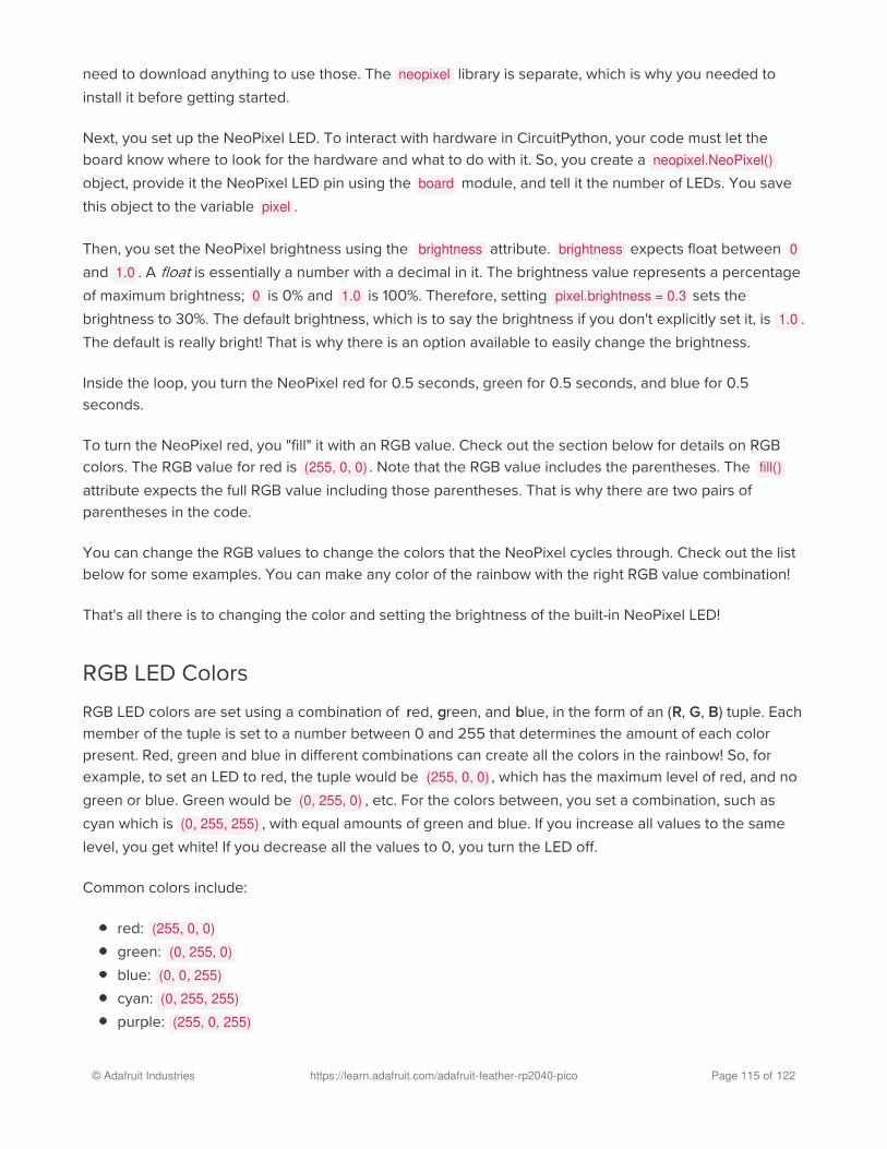
need to download anything to use those. The neopixel library is separate, which is why you needed to
install it before getting started.
Next, you set up the NeoPixel LED. To interact with hardware in CircuitPython, your code must let the
board know where to look for the hardware and what to do with it. So, you create a neopixel.NeoPixel()object, provide it the NeoPixel LED pin using the board module, and tell it the number of LEDs. You save
this object to the variable pixel .
Then, you set the NeoPixel brightness using the brightness attribute. brightness expects float between 0and 1.0 . A float is essentially a number with a decimal in it. The brightness value represents a percentage
of maximum brightness; 0 is 0% and 1.0 is 100%. Therefore, setting pixel.brightness = 0.3 sets the
brightness to 30%. The default brightness, which is to say the brightness if you don't explicitly set it, is 1.0 .
The default is really bright! That is why there is an option available to easily change the brightness.
Inside the loop, you turn the NeoPixel red for 0.5 seconds, green for 0.5 seconds, and blue for 0.5
seconds.
To turn the NeoPixel red, you "fill" it with an RGB value. Check out the section below for details on RGB
colors. The RGB value for red is (255, 0, 0) . Note that the RGB value includes the parentheses. The fill()attribute expects the full RGB value including those parentheses. That is why there are two pairs of
parentheses in the code.
You can change the RGB values to change the colors that the NeoPixel cycles through. Check out the list
below for some examples. You can make any color of the rainbow with the right RGB value combination!
That's all there is to changing the color and setting the brightness of the built-in NeoPixel LED!
RGB LED Colors
RGB LED colors are set using a combination of red, green, and blue, in the form of an (R, G, B) tuple. Each
member of the tuple is set to a number between 0 and 255 that determines the amount of each color
present. Red, green and blue in different combinations can create all the colors in the rainbow! So, for
example, to set an LED to red, the tuple would be (255, 0, 0) , which has the maximum level of red, and no
green or blue. Green would be (0, 255, 0) , etc. For the colors between, you set a combination, such as
cyan which is (0, 255, 255) , with equal amounts of green and blue. If you increase all values to the same
level, you get white! If you decrease all the values to 0, you turn the LED off.
Common colors include:
red: (255, 0, 0)green: (0, 255, 0)blue: (0, 0, 255)cyan: (0, 255, 255)purple: (255, 0, 255)
© Adafruit Industries https://learn.adafruit.com/adafruit-feather-rp2040-pico Page 115 of 122

yellow: (255, 255, 0)white: (255, 255, 255)black (off): (0, 0, 0)
NeoPixel Rainbow
You should have already installed the library necessary to use the built-in NeoPixel LED. If not, follow the
steps at the beginning of the NeoPixel Color and Brightness section to install it.
Update your code.py to the following, and save.
"""CircuitPython NeoPixel Rainbow example for Feather RP2040"""import timeimport boardimport neopixelfrom _pixelbuf import colorwheel
pixel = neopixel.NeoPixel(board.NEOPIXEL, 1, auto_write=False)
pixel.brightness = 0.3
def rainbow(delay): for color_value in range(255): for led in range(1): pixel_index = (led * 256 // 1) + color_value pixel[led] = colorwheel(pixel_index & 255) pixel.show() time.sleep(delay)
while True: rainbow(0.02)
The NeoPixel displays a rainbow cycle!
© Adafruit Industries https://learn.adafruit.com/adafruit-feather-rp2040-pico Page 116 of 122

This example builds on the previous example.
First, you import the same three modules and libraries. In addition to those, you import colorwheel .
The NeoPixel hardware setup is similar, but you now also set auto_write to False . This means that now
the NeoPixel won't change unless you explicitly tell it to by calling show() . This is necessary for this
example to speed up the rainbow animation. Brightness setting is the same.
Next, you have the rainbow() helper function. This helper displays the rainbow cycle. It expects a delay in
seconds. The higher the number of seconds provided for delay , the slower the rainbow will cycle. The
helper cycles through the values of the color wheel to create a rainbow of colors.
Inside the loop, you call the rainbow helper with a 0.2 second delay, by including rainbow(0.2) .
That's all there is to making rainbows using the built-in NeoPixel LED!
© Adafruit Industries https://learn.adafruit.com/adafruit-feather-rp2040-pico Page 117 of 122

CPU Temperature
There is a temperature sensor built into the CPU on your microcontroller board. It reads the internal CPU
temperature, which varies depending on how long the board has been running or how intense your code
is.
CircuitPython makes it really simple to read this data from the temperature sensor built into the
microcontroller. Using the built-in microcontroller module, you can easily read the temperature.
Microcontroller Location
The microcontroller on the Feather RP2040 is located to
the right-center of the board, nested between the Adafruit
Feather RP2040 label on the silk.
Reading the Microcontroller Temperature
The data is read using two lines of code. All necessary modules are built into CircuitPython, so you don't
need to download any extra files to get started.
Connect to the serial console (https://adafru.it/Bec), and then update your code.py to the following and
save.
"""CircuitPython CPU temperature example in Celsius"""import timeimport microcontroller
while True: print(microcontroller.cpu.temperature) time.sleep(0.15)
© Adafruit Industries https://learn.adafruit.com/adafruit-feather-rp2040-pico Page 118 of 122

The CPU temperature in Celsius is printed out to the serial console!
Try putting your finger on the microcontroller to see the temperature change.
The code is simple. First you import two modules: time and microcontroller . Then, inside the loop, you print
the microcontroller CPU temperature, and the time.sleep() slows down the print enough to be readable.
That's it!
You can easily print out the temperature in Fahrenheit by adding a little math to your code, using this
simple formula: Celsius * (9/5) + 32.
Update your code.py to the following, and save.
"""CircuitPython CPU temperature example in Fahrenheit"""import timeimport microcontroller
while True: print(microcontroller.cpu.temperature * (9 / 5) + 32) time.sleep(0.15)
The CPU temperature in Fahrenheit is printed out to the serial console!
That's all there is to reading the CPU temperature using CircuitPython!
© Adafruit Industries https://learn.adafruit.com/adafruit-feather-rp2040-pico Page 119 of 122

Downloads
Files:
RP2040 Datasheet (https://adafru.it/QTf)
EagleCAD PCB Files on GitHub (https://adafru.it/R1F)
3D Models on GitHub (https://adafru.it/ScV)
Fritzing object in the Adafruit Fritzing Library (https://adafru.it/R2a)
Feather RP2040 pinout diagram SVG (https://adafru.it/Rdm)
The Feather_RP2040.uf2 file below is the code that ships on the Feather RP2040.
https://adafru.it/Sd9
Schematic
Note: The schematic references 2MB Flash. The Feather RP2040 ships with 8MB flash. The pinouts are
the same.
Fab Print
https://adafru.it/Sd9
© Adafruit Industries https://learn.adafruit.com/adafruit-feather-rp2040-pico Page 120 of 122

3D Model
© Adafruit Industries https://learn.adafruit.com/adafruit-feather-rp2040-pico Page 121 of 122

© Adafruit Industries Last Updated: 2021-07-21 12:22:58 PM EDT Page 122 of 122

Mouser Electronics
Authorized Distributor
Click to View Pricing, Inventory, Delivery & Lifecycle Information: Adafruit:
4884