intro to p25
DESCRIPTION
p25 radioTRANSCRIPT

A passion for performance.
Introduction toProject 25

Introduction
This booklet is designed to give an introduction to the Project 25radio standard and its technology.
Like most digital radio standards it raises some new test require-ments and the solution to some of these tests is considered using theIFR 2975 Project 25 Radio Test Set.
1

What is Project 25?
Project 25 is a digital radio system designed specifically for publicsafety applications by police, fire and medical services. It will also findapplications with utility operators and other government agencies.
With interoperability and maximizing radio spectrum efficiency asfundamental requirements, Project 25 Phase I uses digital voiceencoding to reduce the required bandwidth for speech transmission to12.5 kHz, while simultaneously maintaining backward compatibility andinteroperation with the existing 25 kHz analog FM systems. A furtherdevelopment of the specification will reduce the required transmissionbandwidth for voice down to 6.25 kHz, thus freeing up more spectrumfor future use.
The Project 25 specifications are available in the public domain,enabling multiple equipment vendors to compete for this market withthe objective of reducing end user costs and providing interoperabilityboth within and between user communities.
2

Who will use Project 25?
Project 25 has a considerable amount of flexibility so that it can betailored to specific user requirements allowing it to appeal to a broadrange of users. While designed with public safety applications in mind,it will also appeal to the security services who are able to use a higherlevel of encryption to reduce the chance of interception. As a generalpurpose trunked radio system, it is capable of serving the wider needof communications for transport operators and the forest service.
3
What does Project 25 do?
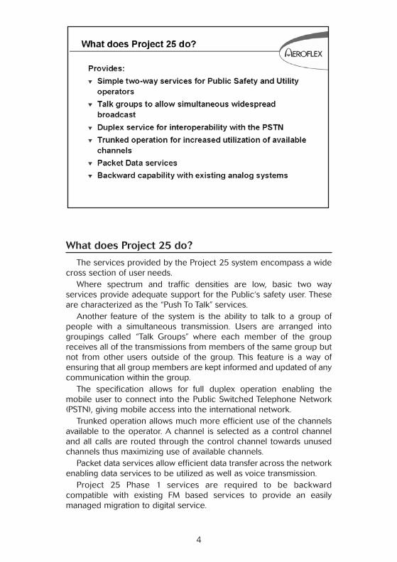
The services provided by the Project 25 system encompass a widecross section of user needs.
Where spectrum and traffic densities are low, basic two wayservices provide adequate support for the Public‘s safety user. Theseare characterized as the “Push To Talk” services.
Another feature of the system is the ability to talk to a group ofpeople with a simultaneous transmission. Users are arranged intogroupings called “Talk Groups” where each member of the groupreceives all of the transmissions from members of the same group butnot from other users outside of the group. This feature is a way ofensuring that all group members are kept informed and updated of anycommunication within the group.
The specification allows for full duplex operation enabling themobile user to connect into the Public Switched Telephone Network(PSTN), giving mobile access into the international network.
Trunked operation allows much more efficient use of the channelsavailable to the operator. A channel is selected as a control channeland all calls are routed through the control channel towards unusedchannels thus maximizing use of available channels.
Packet data services allow efficient data transfer across the networkenabling data services to be utilized as well as voice transmission.
Project 25 Phase 1 services are required to be backwardcompatible with existing FM based services to provide an easilymanaged migration to digital service.
4

Project 25 features
Some of the features that make Project 25 suitable for public safetyuse are given here.
Priority calling enables calls to be ranked in importance so that thesystem is always available for high priority traffic such as emergencycalls. These are usually accessed from a single key push on theterminal.
Encryption prevents call interception and ensures that the commu-nication is kept secure.
Call Alert and User ID are used to keep the user fully informed of thestatus of the communication channel in use.
Group Calling allows a message to be broadcast to all othermembers of a specific group.
Affiliation enables the members of the group to change to meetoperational requirements. This can be done over the air allowingdynamic reconfiguration of talk groups. Encryption keys can also bechanged in this way to retain security within the talk groups.
5

Goal - Interoperability
User groups can be dynamically reconfigured over the air so thatcommunications can be maintained between all those required to bein attendance. Cross-Band Repeaters can also be used when agenciesare allocated different frequency plans.
6

Goal - Spectrum Efficiency
Existing analog technology supports voice traffic in a bandwidth of 25 kHz. The use of digital technology allows the same voice quality tobe transmitted in a 12.5 kHz bandwidth for Project 25 Phase 1. In thefuture a more complex modulation will allow the same voice infor-mation to be transmitted in a 6.25 kHz bandwidth.
7

Frequency Bands Allocated
Although designed for application across a broad frequency range,Project 25 is regulated to the above frequencies for public safety appli-cations within the USA. The 800 MHz frequencies provide a full duplexchannel if required with an offset of 45 MHz.
More spectrum may become available in the 700 MHz frequencyrange as the analog TV channels are taken out of service. Currently theallocation of this additional spectrum is the subject of much debate.
8

Basic System Components
This graphic shows the basic system components. Mobile terminals,either vehicular mounted or portable, communicate in normal mode tothe Base repeaters. These are interconnected with a land line ormicrowave link to the main switch in the base station. Depending onsystem complexity, a Trunking controller may be included to providemore efficient use of spectrum if the traffic level demands it. Interfacesto a dispatch console complete the basic system and a PSTN inter-connect can also be provided.
Additionally, the terminals have a talk around facility which allowsdirect communication between mobiles without the need for the infra-structure.
9
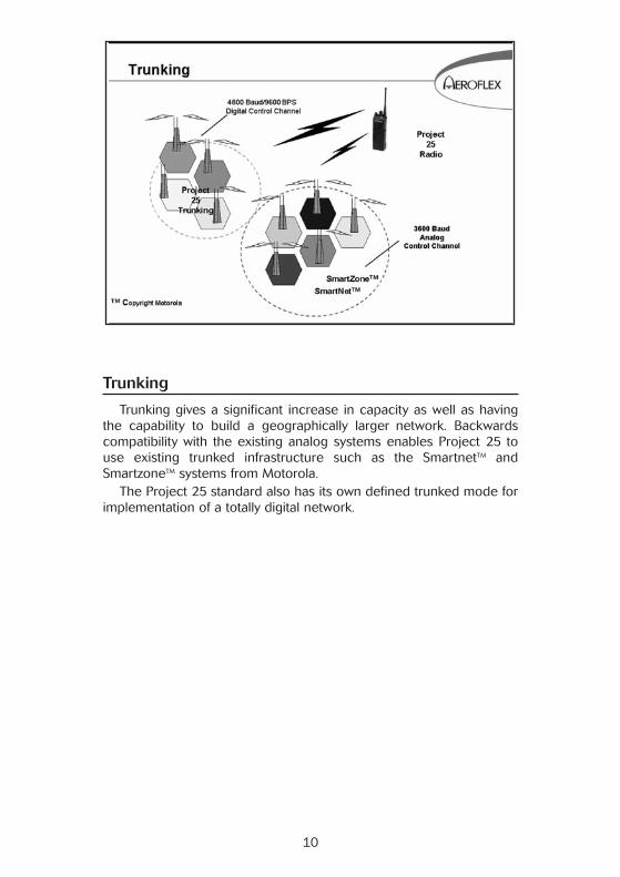
Trunking
Trunking gives a significant increase in capacity as well as havingthe capability to build a geographically larger network. Backwardscompatibility with the existing analog systems enables Project 25 touse existing trunked infrastructure such as the SmartnetTM andSmartzoneTM systems from Motorola.
The Project 25 standard also has its own defined trunked mode forimplementation of a totally digital network.
10

Analog vs. Digital
In order to obtain an acceptable voice quality using analog FMmodulation, a channel bandwidth approaching 25 kHz is required.Additionally, signaling to maintain the radio link and provide callmanagement occupies some of the available resource.
The use of a high level modulation called Continuous 4 level FM(C4FM) enables 9600 bits to be transmitted in a 12.5 kHz channel. Thisenables error correction information to be transmitted along with thevoice signal and signaling information. The error correction is able tocorrect for small errors in the received signal thus providing a morerobust service without any of the background hiss that you hear onanalog systems as they get near the edge of range.
The Phase II implementation will use a further increase inmodulation complexity to support the same 9600 bits in a 6.25 kHzchannel.
11

How do we convert Analog to Digital?
In a digital system the voice is encoded into a bit stream by a devicecalled a Vocoder. Various techniques are used to do this and the oneselected for use in Project 25 is called an Improved Multi-BandExcitation (IMBE) Vocoder. This uses complex algorithms to reduceeach 20ms of speech to 88 bits of information to be transmitted overthe radio link. The receiving device reverses the process to produce20ms of analog speech signal.
The IMBE Vocoder converts a 3100 Hz audio band (300-3400 Hz)to a 4400 bps digital signal.
12

Modulation
The Phase I implementation of Project 25 uses a modified form offour level FM as its modulation technique. The information is trans-mitted in the form of a digital data stream and is modulated as symbols.Each symbol type is determined by two bits of data giving four symboltypes in total. The symbol types are represented by a particular FMdeviation applied to the carrier. The modulation is characterized asbeing complex because the deviation is not symmetrical about thecarrier as you would expect in a conventional FM system although it isof fixed amplitude.
Compatible Quadrature Phase Shift Keying (CQPSK) has beenconsidered as a possibility for Phase II modulation. With CQPSK, eachsymbol is identified by the phase change from the previous symbol.This is one of a family of modulations generally grouped under the termof linear modulation in which both the phase and the amplitude of thesignal vary from symbol to symbol.
13
Project 25 - Logical Message Structure
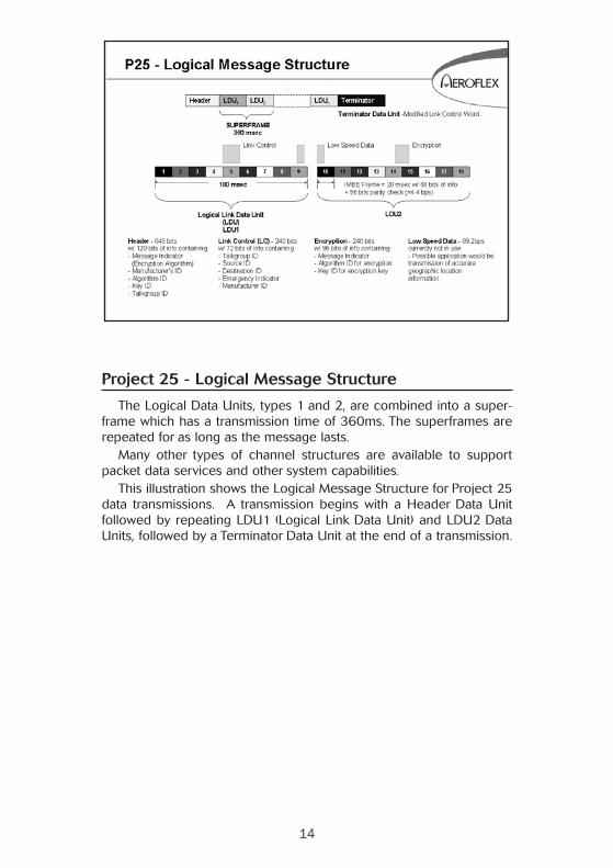
The Logical Data Units, types 1 and 2, are combined into a super-frame which has a transmission time of 360ms. The superframes arerepeated for as long as the message lasts.
Many other types of channel structures are available to supportpacket data services and other system capabilities.
This illustration shows the Logical Message Structure for Project 25data transmissions. A transmission begins with a Header Data Unitfollowed by repeating LDU1 (Logical Link Data Unit) and LDU2 DataUnits, followed by a Terminator Data Unit at the end of a transmission.
14

Header Data Unit
The Header Data Unit begins with 48 bits of Synchronization alongwith 64 bits for the Network Identifier. The Network Access Code(NAC) contains values expressed in HEX format that range through4096 values. A subset of these codes are intended to map intoContinuous Tone Coded Squelch (CTCSS) and Digital Coded Squelch(DCS) codes. NAC codes 023 through 271 directly correlate to DCScodes 023 through 271. NAC code 293 is the default for carriersquelch.
15

Frame Structure for a Voice Channel
The frame and message structure of the Project 25 system is brieflydescribed in the following graphics. As mentioned earlier, the speechis divided up into 20ms segments, each being represented by 88 bitsof data. To these 88 bits a further 56 bits of parity data are added tocomplete a voice frame. Nine of the voice frames are concatenatedalong with some system messaging to form a Logical Link Data Unit of180ms in length. Additional protection is given to the speech framesby interleaving them throughout the Data Unit. This ensures that if thetransmission is impaired for a short period of time, many small and thusinsignificant segments of the speech are lost rather than a completeword.
The Logical Link Data Units are of two types for a voice channel. Unit1 contains the link control information which is used to maintain thecommunication channel. Unit 2 contains the encryption synchro-nization information. Both Unit 1 and Unit 2 also contain some lowspeed data service divided equally between the units.
16

Link Control Word (Data Unit 1)
The Link Control Word used in the Logical Link Data Unit 1 can beof several formats. Two of the more common ones are shown in thisillustration. The first bits transmitted identify the particular format inuse. This is followed by the terminal manufacturer’s identity code whichis common to all of the link control formats. Other informationconveyed in this 72 bit field includes the Emergency bit which is setwhen a high priority call is made, the Talk Group identity of the mobileand the individual identity within the talk group. Several fields are leftunused for future applications allowing further system growth. Again, aswith the voice frame, additional parity bits are included, 168 in thiscase to provide error correction of the transmitted data.
17

Link Control Word (Data Unit 2)
The other basic data units are described on this graphic. TheEncryption synchronization data is included in Logical Data Unit 2 andconsists of 96 data bits which comprise 72 bits of message indicator,8 bits describing the encryption algorithm and 16 bits identifying theencryption key in use. Again, this is protected by a further 144 paritybits.
Every message is preceded by a Header Data Unit and followed bya Terminator Data Unit. The Header Data Unit contains the MessageIndicator and the Manufacturer’s Identity as well as encryption and talkgroup information.
The Terminator Data Unit is a modified form of the Link Control Wordpreviously described. The data units are then built up into a messagestructure shown on the graphic.
18

19
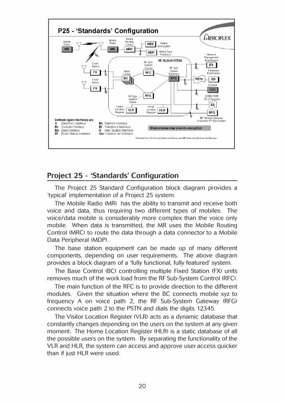
Project 25 - ‘Standards’ Configuration
The Project 25 Standard Configuration block diagram provides a‘typical’ implementation of a Project 25 system.
The Mobile Radio (MR) has the ability to transmit and receive bothvoice and data, thus requiring two different types of mobiles. Thevoice/data mobile is considerably more complex than the voice onlymobile. When data is transmitted, the MR uses the Mobile RoutingControl (MRC) to route the data through a data connector to a MobileData Peripheral (MDP).
The base station equipment can be made up of many differentcomponents, depending on user requirements. The above diagramprovides a block diagram of a ‘fully functional, fully featured’ system.
The Base Control (BC) controlling multiple Fixed Station (FX) unitsremoves much of the work load from the RF Sub-System Control (RFC).
The main function of the RFC is to provide direction to the differentmodules. Given the situation where the BC connects mobile xyz tofrequency A on voice path 2, the RF Sub-System Gateway (RFG)connects voice path 2 to the PSTN and dials the digits 12345.
The Visitor Location Register (VLR) acts as a dynamic database thatconstantly changes depending on the users on the system at any givenmoment. The Home Location Register (HLR) is a static database of allthe possible users on the system. By separating the functionality of theVLR and HLR, the system can access and approve user access quickerthan if just HLR were used.
20

Project 25 - Unit to Unit Sequence Diagram
The following call processing ladder diagrams show the genericmessage sequences used in various Project 25 calling scenarios.
Message Acronym Definition
UU_V_REQ Unit to Unit Voice Service RequestUU_ANS_REQ Unit to Unit Answer RequestUU_V_CH_GRANT Unit to Unit Voice Channel GrantUU_ANS_RSP Unit to Unit Answer ResponseCAN_SRV_REQ Cancellation of Service Request
21

Project 25 - Unit to PSTN Sequence Diagram
Message Acronym Definition
TELE_INT_DIAL_REQ Telephone interconnect voice servicerequest (Explicit dialing)
TELE_INT_PSTN_REQ Telephone interconnect voice servicerequest (Implicit dialing)
CAN_SRV_REQ Cancellation of Service Request
22

Project 25 - Unit to Group
Message Acronym Definition
GRP_V_REQ Group Voice Service RequestGRP_V_CH_GRANT Group Channel GrantUU_ANS_RSP Unit to Unit Answer Response
23

Project 25 - PSTN to Unit Sequence Diagram
Message Acronym Definition
TELE_INT_ANS_REQ Telephone Interconnect Answer RequestTLE_INT_ANS_RSP Telephone Interconnect Answer Response
24

Project 25 Transmitter Measurements
Decoding of the Uplink data from a Project 25 transmitter allowsverification of radio programming. The NAC, TGID (Talk Group ID) andSID (System ID) are the primary fields required to establish communi-cations.
25

Power Measurement
The power measurement of Project 25 transmitters can be made inthe conventional manner with a power meter. The terminal or repeaterproduces a continuous signal whenever the transmitter is keyed.
26
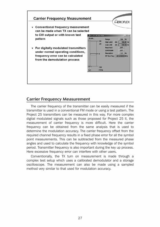
Carrier Frequency Measurement
The carrier frequency of the transmitter can be easily measured if thetransmitter is used in a conventional FM mode or using a test pattern. TheProject 25 transmitters can be measured in this way. For more complexdigital modulated signals such as those proposed for Project 25 II, themeasurement of carrier frequency is more difficult. Here the carrierfrequency can be obtained from the same analysis that is used todetermine the modulation accuracy. The carrier frequency offset from therequired channel frequency results in a fixed phase error for all the symbolpoint measurements. This can be subtracted from the measured phaseangles and used to calculate the frequency with knowledge of the symbolperiod. Transmitter frequency is also important during the key up process.Here excessive frequency error can interfere with other users.
Conventionally, the TX turn on measurement is made through acomplex test setup which uses a calibrated demodulator and a storageoscilloscope. The measurement can also be made using a sampledmethod very similar to that used for modulation accuracy.
27

Modulation Accuracy (C4FM)
As described in the previous page, Project 25 in its first phase usesa constant amplitude modulation which is a modified form of FM.Therefore, modulation accuracy can be measured by conventionaldeviation measurements as long as a suitably modified data stream istransmitted. This would first consist of transmitting all the low deviationbits (i.e. 00 for + dev, 10 for –dev) to ascertain the low deviation andthen a bit pattern containing the high deviation levels (i.e. 01 for +dev,11 for – dev). This, of course, prevents conventional measurement frombeing used on a working transmitter where the bit pattern is controlledby the message being transmitted.
For the more complex systems such as that proposed for Project 25II the data is represented by the instantaneous phase and amplitude ofa vector. Measuring the fidelity of this type of modulation is much moredifficult. One method takes a sample of the transmitted waveform overa large number of symbols (typically 100-200). From this informationthe demodulated data can be determined. This enables the testequipment to calculate the phase trajectory created by the data andthen compare this with the sampled data. The errors in the measureddata can then be determined and resolved into their various compo-nents.
28
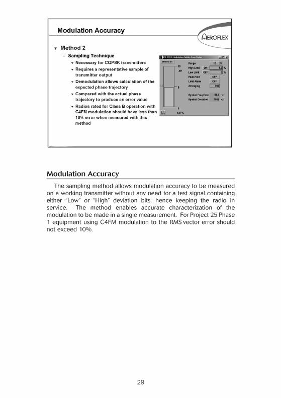
Modulation Accuracy
The sampling method allows modulation accuracy to be measuredon a working transmitter without any need for a test signal containingeither “Low” or “High” deviation bits, hence keeping the radio inservice. The method enables accurate characterization of themodulation to be made in a single measurement. For Project 25 Phase1 equipment using C4FM modulation to the RMS vector error shouldnot exceed 10%.
29

Summary
As shown previously in the booklet, Project 25 provides betterspectral efficiency due to its digital modulation technique. This type ofmodulation provides twice as many communications channels as thetraditional FM analog scheme.
Interoperability is enhanced as more public safety organizationsconvert to a common Project 25 compliant system.
DES Type III encryption allows for better security when specificgroups need private conversations and Project 25 allows for Over-The-Air-Rekeying (OTAR) to reconfigure encryption keys.
Project 25 requires unique testing techniques due to its digitalformat. Transmitter modulation must be decoded and processed inorder to verify that a receiver will be able to process the intendedmessage. The Project 25 Receiver must be tested with encrypted andunencrypted messages to ensure proper operation. Cross-BandRepeaters may require testing across different frequency bands.
30
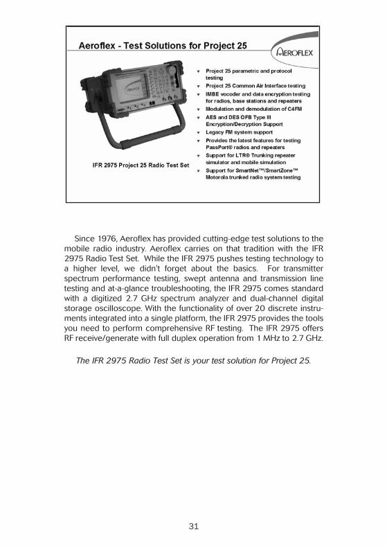
Since 1976, Aeroflex has provided cutting-edge test solutions to themobile radio industry. Aeroflex carries on that tradition with the IFR2975 Radio Test Set. While the IFR 2975 pushes testing technology toa higher level, we didn't forget about the basics. For transmitterspectrum performance testing, swept antenna and transmission linetesting and at-a-glance troubleshooting, the IFR 2975 comes standardwith a digitized 2.7 GHz spectrum analyzer and dual-channel digitalstorage oscilloscope. With the functionality of over 20 discrete instru-ments integrated into a single platform, the IFR 2975 provides the toolsyou need to perform comprehensive RF testing. The IFR 2975 offersRF receive/generate with full duplex operation from 1 MHz to 2.7 GHz.
The IFR 2975 Radio Test Set is your test solution for Project 25.
31

32


Introduction to
Project 25
Our passion for performance is defined by three attributes represented by these three icons:
solution-minded, performance-driven and customer-focused.
Part No. 46891/894
Issue 4
05/09
As we are always seeking to improve our products, the information in this document givesonly a general indication of the product capacity, performance and suitability, none of whichshall form part of any contract. We reserve the right to make design changes without notice.All trademarks are acknowledged. Parent company Aeroflex, Inc. ©Aeroflex 2009.
CHINA Beijing Tel: [+86] (10) 6539 1166 • Fax: [+86] (10) 6539 1778
CHINA Shanghai Tel: [+86] (21) 5109 5128 • Fax: [+86] (21) 5150 6112
FINLAND Tel: [+358] (9) 2709 5541 • Fax: [+358] (9) 804 2441
FRANCE Tel: [+33] 1 60 79 96 00 • Fax: [+33] 1 60 0177 69 22
GERMANY Tel: [+49] 8131 2926-0 • Fax: [+49] 8131 2926-130
HONG KONG Tel: [+852] 2832 7988 • Fax: [+852] 2834 5364
INDIA Tel: [+91] (0) 80 4115 4501 • Fax: [+91] (0) 80 4115 4502
JAPAN Tel: [+81] 3 3500 5591 • Fax: [+81] 3 3500 5592
KOREA Tel: [+82] (2) 3424 2719 • Fax: [+82] (2) 3424 8620
SCANDINAVIA Tel: [+45] 9614 0045 • Fax: [+45] 9614 0047
SPAIN Tel: [+34] (91) 640 11 34 • Fax: [+34] (91) 640 06 40
UK Cambridge Tel: [+44] (0) 1763 262277 • Fax: [+44] (0) 1763 285353
UK Stevenage Tel: [+44] (0) 1438 742200 • Fax: [+44] (0) 1438 727601Freephone: 0800 282388 (UK only)
USA Tel: [+1] (316) 522 4981 • Fax: [+1] (316) 522 1360Toll Free: 800 835 2352 (US only)
w w w . a e r o f l e x . c o m
i n f o - t e s t @ a e r o f l e x . c o m