intesisbox me-ac-knx-15, me-ac-knx-100 installation · pdf fileknx system, with the same...
TRANSCRIPT
IntesisBox®-KNX Mitsubishi Electric G50 v10 r15 eng
Doc: IntesisBox-KNX Mitsubishi Electric G50 v10 r15 eng.pdf
1IntesisBox is a registered trademark of Intesis Software SL
IntesisBox®-KNXMitsubishi Electric G-50A/GB-50A TCP/IP XML
Gateway for integration of Mitsubishi Electric City Multi air conditioning systems into KNX
TP-1 (EIB) systems.
Two models are available for this gateway, with the following Order Codes:
• ME-AC-KNX-15. Model supporting up to 15 City Multi groups.
• ME-AC-KNX-100. Model supporting up to 100 City Multi groups.
IntesisBox®-KNX Mitsubishi Electric G50 v10 r15 eng
Doc: IntesisBox-KNX Mitsubishi Electric G50 v10 r15 eng.pdf
2IntesisBox is a registered trademark of Intesis Software SL
INDEX
1. Description.......................................................................................................... 3
1.1 Introduction................................................................................................... 3
1.2 Functionality .................................................................................................. 4
1.3 Limitations .................................................................................................... 5
2. KNX System........................................................................................................ 6
2.1 Description .................................................................................................... 6
2.2 Points definition ............................................................................................. 7
3. LinkBoxEIB. Configuration & monitoring tool for intesisBox KNX series. ...................... 8
3.1 Introduction................................................................................................... 8
3.2 Project definition ............................................................................................ 8
3.3 Connection configuration............................................................................... 13
3.4 Signals configuration .................................................................................... 15
3.4.1 Remember ............................................................................................. 19
3.4.2 Restrictions............................................................................................ 20
3.4.3 Conventions ........................................................................................... 20
3.5 Saving the configuration and Sending it to the gateway .................................... 20
3.6 Signals viewer.............................................................................................. 20
3.7 System commands ....................................................................................... 22
3.8 Files ........................................................................................................... 23
4. Setup process and troubleshooting....................................................................... 24
4.1 Pre-requisites .............................................................................................. 24
4.2 Setup procedure........................................................................................... 24
5. Connections ...................................................................................................... 27
6. Mechanical & electrical characteristics................................................................... 28
7. Dimensions ....................................................................................................... 29
8. Annexes ........................................................................................................... 30
8.1 Gateways Mitsubishi Electric G-50A and GB-50A............................................... 30
IntesisBox®-KNX Mitsubishi Electric G50 v10 r15 eng
Doc: IntesisBox-KNX Mitsubishi Electric G50 v10 r15 eng.pdf
3IntesisBox is a registered trademark of Intesis Software SL
1. Description
1.1 Introduction
IntesisBox®-KNX Mitsubishi Electric G50 is a communication gateway for the integration of
Mitsubishi Electric City Multi air conditioning systems into KNX TP-1 (EIB).
This integration requires the Mitsubishi Electric City Multi AC system be equipped with the
Mitsubishi Electric G-50A or GB-50A gateway with XML option. This gateway from
Mitsubishi Electric offers the signals of the City Multi AC system through XML protocol. Every
G50 (G-50A or GB-50A) allows access to the signals of up to 50 City Multi indoor units and
50 groups, no matter the number of outdoor units installed. In the G50, the group is the
control unit, every group can have from 1 to 16 associated indoor units. This integration
supervise and control groups, not indoor units, although if only one indoor unit is associated
to every group then you can supervise and control indoor units individually.
This G50 gateway is supplied by Mitsubishi Electric. The difference between the G-50A and
GB-50A is that the first incorporates display and keyboard and the second just blind cover.
At integration level, both allow the same functionality. Contact your nearest Mitsubishi
Electric distributor for more details about G-50A and GB-50A. In this document we will refer
to this two gateway models (G-50A and GB-50A) as just G50.
The following list shows the available signals to integrate per every group (of the 50
possible) of the G50:
Property Description / Status
Drive Start/Stop
Read/Write: ON, OFF
Mode Operation Mode
Read/Write: COOL, DRY, FAN, HEAT, AUTO, HEAT RECOVERY,
LC_AUTO, BYPASS
Read: AUTO HEAT, AUTO COOL
SetTemp Temperature Set Point (only integer numbers allowed)
Read/Write: For COOL or DRY Mode:19..30 ºC, for HEAT Mode:
17..28 ºC, for AUTO Mode:19..28 ºC)
AirDirection Air output direction (Vane Position)
Read/Write: HORIZONTAL, MID1, MID2, VERTICAL, SWING
FanSpeed AC fan speed or LOSSNAY
Read/Write: HIGH, MIDH, MIDL, LOW
RemoCon Prohibition for General control from the local panel
Read/Write: PROHIBIT, PERMIT
DriveItem Prohibition for ON/OFF control from the local panel
Read/Write: CHK_ON, CHK_OFF
ModeItem Prohibition for Mode control from the local panel
Read/Write: CHK_ON, CHK_OFF
SetTempItem Prohibition for Set Point control from the local panel
Read/Write: CHK_ON, CHK_OFF
FilterItem Prohibition for Filter Reset control from the local panel
Read/Write: CHK_ON, CHK_OFF
Ventilation Operational status for LOSSNAY or OA
Read/Write: HIGH, LOW, OFF

IntesisBox®-KNX Mitsubishi Electric G50 v10 r15 eng
Doc: IntesisBox-KNX Mitsubishi Electric G50 v10 r15 eng.pdf
4IntesisBox is a registered trademark of Intesis Software SL
FilterSign Status for Filter Dirty
Read: ON, OFF
Write: RESET
ErrorSign Error status
Read: ON, OFF
Write: RESET
InletTemp Ambient Temperature
Read: 0.0 to 99.9
G50
Communication
Error
Communication error with G50
Virtual signal generated by IntesisBox® to indicate the status of the
communication with the G50.
Group
Communication
Error
Group communication error
Virtual signal generated by IntesisBox® to indicate that the group is
not configured into the G50.
For more information consult Mitsubishi Electric technical documentation supplied with the
G50.
1.2 Functionality
Every one of the mentioned signals have to be associated to an EIB group address, with
this, all the system is seen as a one more EIB device, with the same configuration and
functioning characteristics.
IntesisBox-KNX continuously polls (read) all the G50's configured signals and maintains the
updated status of all of them in its memory ready to be served when requested from EIB.
When a change of status is detected in a Mitsubishi Electric signal, a write telegram is sent
to the KNX bus, of the associated EIB Group.
When it is received a telegram from the EIB bus, of an EIB Group address associated to a
Mitsubishi Electric signal, a message is sent immediately to the corresponding G50 to
perform the corresponding action in the Mitsubishi Electric system.
In the continuous polling of the G50, if a non response of the G50 is detected, the
corresponding virtual signal inside the gateway will be activated indicating communication
error with the G50. The same way, there is also a virtual signal per every City Multi group
EIB
KNK
EIB
G50
Ethernet
IntesisBox
LinkBoxEIBConfigurationSoftware
Only needed for configuration
G50
RS232
LANTCP/IP
XML
IntesisBox®-KNX Mitsubishi Electric G50 v10 r15 eng
Doc: IntesisBox-KNX Mitsubishi Electric G50 v10 r15 eng.pdf
5IntesisBox is a registered trademark of Intesis Software SL
to indicate communication error with the group, this signal will be normally activated if the
group is not configured inside the G50. Note that, although the internal units are not
connected physically in the City Multi system, the G50 responds as if they were.
1.3 Limitations
Element Max. Notes
Nb of G50 2 Number of independent G50 Gateways
Nb of City Multi groups:
Nb of G50 x 50
100 Number of groups of AC indoor units
Nb of EIB Groups 5902 Total number of EIB Groups that can be used in
IntesisBox.
Nb of listening addresses 2000 Number of EIB groups that can be used as
listening addresses.
Nb of listening addresses per
EIB Group.
255 Number of listening addresses that can be
associated to an EIB group address.
There are various models of IntesisBox-KNX with different capacity. The limits showed here
are for the model with maximum capacity.
IntesisBox®-KNX Mitsubishi Electric G50 v10 r15 eng
Doc: IntesisBox-KNX Mitsubishi Electric G50 v10 r15 eng.pdf
6IntesisBox is a registered trademark of Intesis Software SL
2. KNX System
In this section, a common description for all IntesisBox-KNX series gateways is given, from
the point of view of KNX system which is called from now on internal system.
2.1 Description
IntesisBox-KNX connects directly to the EIB bus and behaves as one more device of the
KNX system, with the same configuration and functional characteristics as other KNX
devices.
Internally, the electronic circuit part connected to the EIB bus is opto-isolated from the rest
of the electronics.
IntesisBox-KNX receives, manages and sends all the telegrams related to its configuration
to the EIB bus.
On receiving telegrams of EIB Groups associated to the external system (Mitsubishi Electric
G50 in this case), the corresponding messages are sent to the external system to maintain
both systems synchronised in every moment.
When a change in a signal of the external system is detected, a telegram is sent to the EIB
bus (of the associated EIB group) to maintain both systems synchronised in every moment.
The status of the EIB bus is checked continuously and, if a bus drop down is detected, due
to a failure in the bus power supply for example, when the EIB bus is restored again,
IntesisBox will retransmit the status of all the EIB groups marked as "T" Transmit. Also the
Updates of the groups marked as "U" Update will be performed, this last behaviour can be
deactivated.

IntesisBox®-KNX Mitsubishi Electric G50 v10 r15 eng
Doc: IntesisBox-KNX Mitsubishi Electric G50 v10 r15 eng.pdf
7IntesisBox is a registered trademark of Intesis Software SL
2.2 Points definition
Every signal of the external system (Mitsubishi Electric) to use, has the following EIB
properties:
Property Description
Signal Signal's Description. Only for informative purposes, allows to identify the
signal comfortably.
EIS (DataPoint) Is the EIB data type used to code the signal's value. It will depend on the
type of signal associated in the external system in every case. In some
integrations it is selectable, in others it is fixed due to the intrinsic
characteristics of the signal.
Group Is the EIB group to which the signal is associated. It is also the group to
which the read (R), write (W), transmit (T) and update (U) actions are
applied. Is the sending group.
Listening
addresses
They are the addresses that will actuate on the signal, apart of the Group
address.
R Read. If activated, read telegrams of this group will be allowed.
W Write. If activated, write telegrams of this group will be allowed.
T Transmit. If activated, when the signal's value changes, due to a change in
the external system, a write telegram of the group will be sent to the EIB
bus.
U Update. If activated, on IntesisBox start-up or after an EIB bus reset
detection, read telegrams of the sending group will be sent to the EIB bus,
and the value received will be sent to the external system as if it has been
received by a write telegram.
Active If activated, the signal will be active in IntesiBox, if not, the behaviour will
be as if the signal is not defined. Allows to deactivate signals without the
need of delete them for future use.
These properties are common for all IntesisBox-KNX series gateways. Although every
integration may have specific properties according to the type of signals of the external
system in every case.

IntesisBox®-KNX Mitsubishi Electric G50 v10 r15 eng
Doc: IntesisBox-KNX Mitsubishi Electric G50 v10 r15 eng.pdf
8IntesisBox is a registered trademark of Intesis Software SL
3. LinkBoxEIB. Configuration & monitoring tool for intesisBox KNXseries.
3.1 Introduction
LinkBoxEIB is a Windows compatible software tool developed specifically to monitor and
configure IntesisBox-KNX series gateways. It is possible to configure all external protocols
available for IntesisBox-KNX and to maintain different customer’s configurations based on a
LinkBoxEIB project for every different installation. Maintaining always on hard disk a copy of
the last configuration files for every external protocol and customer, that is to say for every
project.
From LinkBoxEIB, as well as configure the integration signals list and connection parameters
for every external protocol, it is permitted also to select the serial port to use to connect to
the gateway and the use of some tools for monitoring and debugging de device. Some of
these tools will be explained in this document but only some of them, the rest of available
debugging tools and commands will not be explained here because they are for exclusive
use under the recommendations of Intesis Software technical support.
LinkBoxEIB allows configuring all IntesisBox-KNX series independently of the external
system or protocol used. For every external system, LinkBoxEIB has a specific
configuration window. Periodically, new free versions of LinkBoxEIB are released
incorporating the latest developed integrations for external systems.
3.2 Project definition
The first step to do in LinkBoxEIB for a new installation is to create the installation’s project
giving a descriptive name to it. When you create a project, a new folder is created with the
name of the project containing the configuration files needed depending on the external
protocol selected for the project. It is strongly recommended that you create a new project
for every installation, if not, overwriting of configuration files of previous installations using
the same external protocol may occur, loosing the configuration data for those previous
installations. The projects folder is located in AppFolder\ProjectsEIB, where AppFolder is the
installation folder of LinkBoxEIB (by default C:\Program Files\Intesis\LinkBoxEIB). Inside
the projects folder, a new folder will be created for every project defined in LinkBoxEIB with
the files needed for the project.
When you open LinkBoxEIB, the project selection window will appear inviting you to select
a project or create a new one. A demo project for every external protocol supported is
provided with the standard installation of LinkBoxEIB. You can create a new project or
select a demo project based on the external protocol desired, and create a new one from
the demo one selected.

IntesisBox®-KNX Mitsubishi Electric G50 v10 r15 eng
Doc: IntesisBox-KNX Mitsubishi Electric G50 v10 r15 eng.pdf
9IntesisBox is a registered trademark of Intesis Software SL
Project selection window
To create a new project, select a project using the same external protocol you want to use
in the new project and push New button. You will be prompted to create a copy of the
selected project (useful for similar installations) or create a new one.
If you select Yes you will be prompted to specify a name and a description for the new
project that will be based on the same external protocol than the selected one. If you select
No you can specify a name, a description and an external protocol to use from the list of
available external protocols.
IntesisBox®-KNX Mitsubishi Electric G50 v10 r15 eng
Doc: IntesisBox-KNX Mitsubishi Electric G50 v10 r15 eng.pdf
10IntesisBox is a registered trademark of Intesis Software SL
On Accept, a new folder will be created inside the projects folder with the name given to the
project, this folder will contain the template configuration files if the project is a brand new
one, or a copy of the configuration files if it is a copy of a selected one.
A description of the files created for a Mitsubishi Electric G50 protocol based project can be
found in section Files below in this document.
From all the possibilities of LinkBoxEIB, only changes in configuration for the integration and
configuration file generation can be performed while disconnected from the gateway
(working off-line), allowing you to do these tasks in the office more comfortably. Before any
monitoring or downloading action to the gateway can be performed, the connection between
the gateway and the PC running LinkBoxEIB must be established (working on-line). To do
so follow these steps:
1. Make sure the gateway is powered-up an correctly connected to the KNX-EIB system via
the EIB bus and to the Mitsubishi Electric G50's via the Ethernet connection (consult
details for connection and pin assignments in section Connections of this document).
2. Connect a free PC serial port to the gateway's serial port marked as PC Console. (Use
the standard serial cable supplied with the gateway or make your own cable following
the pin assignments specified in section Connections in this document).
3. Select in LinkBoxEIB the PC serial port used for the connection to the gateway. Use
menu Configuration -> Connection.
4. Check the checkbox off-line under the menu bar (it will change automatically to on-line)
and LinkBoxEIB will ask for INFO about the gateway connected to it via the serial
connection, if the connection is ok then the gateway will respond with its identification
(this can be monitored in the IntesisBox Communication Console window, as showed
below).
IntesisBox®-KNX Mitsubishi Electric G50 v10 r15 eng
Doc: IntesisBox-KNX Mitsubishi Electric G50 v10 r15 eng.pdf
11IntesisBox is a registered trademark of Intesis Software SL
Once connected to the gateway, all the options of LinkBoxEIB are fully operative.
To monitor the communication between the gateway and the KNX system, select the menu
View -> Bus -> EIB. The EIB communication Viewer window will be opened. This window
shows in real time all the communication frames between the gateway and the KNX system
as well as debugging messages referent to the internal protocol (KNX) sent by the gateway.
To monitor the communication between the gateway and the external system (Mitsubishi
Electric G50 in this case), select the menu View -> Bus -> External system. The External
protocol communication viewer window will be opened. This window shows in real time all
the communication frames between the gateway and the G50s as well as debugging
messages referent to external protocol (ME G50) sent by the gateway.

IntesisBox®-KNX Mitsubishi Electric G50 v10 r15 eng
Doc: IntesisBox-KNX Mitsubishi Electric G50 v10 r15 eng.pdf
12IntesisBox is a registered trademark of Intesis Software SL

IntesisBox®-KNX Mitsubishi Electric G50 v10 r15 eng
Doc: IntesisBox-KNX Mitsubishi Electric G50 v10 r15 eng.pdf
13IntesisBox is a registered trademark of Intesis Software SL
To configure the integration connection parameters, and the signals list, select menu
Configuration -> IntesisBox. The Mitsubishi Electric G50 Configuration window will be
opened.
3.3 Connection configuration
Select the Connection tab to configure the connection parameters.
Three kinds of information are configured using this window, the IP parameters of
IntesisBox, the parameters of the KNX interface, and the parameters of the Mitsubishi
Electric interface.
IntesisBox IP configuration parameters:
IntesisBox IP Configuration
1. Enter the IP address for IntesisBox (supplied by the network administrator).
2. Enter the IP NetMask for IntesisBox (supplied by the network administrator).
3. Enter the Default Gateway address (router address) in case IntesisBox is in a different
sub network than the G50s (supplied by the network administrator). Leave blank if there is
no need of router address.
KNX interface configuration parameters:
EIB configuration
1. Enter the physical address desired for IntesisBox inside the KNX network.
1
2
3
1

IntesisBox®-KNX Mitsubishi Electric G50 v10 r15 eng
Doc: IntesisBox-KNX Mitsubishi Electric G50 v10 r15 eng.pdf
14IntesisBox is a registered trademark of Intesis Software SL
Mitsubishi Electric interface configuration parameters:
Mitsubishi Electric G50 Configuration
1. List of G50 devices.
Select a device to configure its properties:
2. IP address of the G50.
3. TCP port, normally 80.
4. Descriptive name, optional.
5. Polling cadence for G50s, in milliseconds, is the refresh frequency for the G50's signals.
6. Polling cycles to validate the return of status for any command sent to Mitsubishi.
7. Use the button to automatically define (and insert in the list) the number of G50s to
connect to. Take into account that the number of G50s defined must be in accordance
with the gateway model used. There are two models, with the following order codes:
• ME-AC-KNX-15. Model supporting up to 15 City Multi groups.
• ME-AC-KNX-100. Model supporting up to 100 City Multi groups.
You can identify the model of your gateway by the Order Code printed in the front label
or also by the identification given by the gateway is response to an INFO command, it is
something like this:
IntesisBox_EIB_MITSUBISHIG50-1… -> this is the basic model (up to one G50, up to
15 City Multi groups).
IntesisBox_EIB_MITSUBISHIG50-2… -> this is the extended model (up to two G50s, up
to 100 City Multi groups)
31
5
5
4
2
6
5
IntesisBox®-KNX Mitsubishi Electric G50 v10 r15 eng
Doc: IntesisBox-KNX Mitsubishi Electric G50 v10 r15 eng.pdf
15IntesisBox is a registered trademark of Intesis Software SL
3.4 Signals configuration
Select the Signals tab to configure the signals list (the IntesisBox's internal points).
Signals list
1. #. Signal’s number (edit not permitted). Every row in the grid corresponds to a signal
(point). This column is used only to enumerate the rows in the grid (signals).
2. G50. Number of G50 to which corresponds the signal, referenced to the list of G50s
defined in Tab Connection. Edit not permitted.
3. Group. City Multi group, it refers to the City Multi group of indoor AC units to which
belongs the signal. Every G50 allows access to up to 50 groups. Edit not permitted.
4. Code. Identifies the different signals available per every City Multi group. An
identification code is given to every different signal into the City Multi group, identifying
every signal with an individual code. In section 1.1, an explanation of every signal is
given. A contextual menu appears using mouse right button click over the column
showing all the possible signal codes. Edit not permitted.
5. Signal. Signal's descriptive name (optional). Useful to identify the signal. The default
descriptive name corresponds to the signal's code, but can be edited/modified.
6. EIS. KNX data type (Data point) to encode the signal’s value. See all the possible EIS
using the mouse right-button-click menu available on the column. Edit not permitted.
7. Group. Main EIB group address for the signal. Format: P/I/S or P/S. Features W,R,T,U
explained below will only apply for this main EIB group address, not for listening
addresses (if defined). Is the sending group address.
8. Listening addresses. EIB group addresses that will be listen by the gateway for this
signal, that is to say, if the gateway receives an EIB telegram with destination one of
7 8 91011121 2 3 4 5 6 13
IntesisBox®-KNX Mitsubishi Electric G50 v10 r15 eng
Doc: IntesisBox-KNX Mitsubishi Electric G50 v10 r15 eng.pdf
16IntesisBox is a registered trademark of Intesis Software SL
these listening addresses, then the telegram will be taken into account and the
corresponding action will be performed on this signal. Format: P/I/S or P/S, if more than
one is entered then they must be separated by comma.
9. R. Indicates if this signal is allowed to be read from KNX system. Possible values: “R” or
blank. “R” means feature activated. Edit using the mouse right-button-click pop-up
menu available on the column. Freely configurable, but be cautious (see below).
10. W. Indicates if this signal is allowed to be written from KNX system. Possible values:
“W” or blank. “W” means feature activated. Edit using the mouse right-button-click pop-
up menu available on the column. Freely configurable, but be cautious (see below).
11. T. Indicates if this signal will generate a telegram sending to the KNX system following a
change of the signal’s value, that is to say, any change of value of this signal will be
transmitted to the KNX system if this feature is activated. Possible values: “T” or blank.
“T” means feature activated. Edit using the mouse right-button-click pop-up menu
available on the column. Freely configurable, but be cautious (see below).
12. U. Indicates if this signal will be updated whenever the gateway starts up or after an EIB
bus reset. “U” means feature activated for the main EIB group address (a read of the
main EIB group address will be performed in the KNX system for the update). Blank
means feature not activated. Edit using the mouse right-button-click pop-up menu
available on the column. Freely configurable, but be cautious (see below).
13. Active. Indicates if the signal is active or not for the integration. Possible values: 0-No,
1-Yes. Edit using the mouse right-button-click menu available on the column.
The columns R, W, T, U and Active can be modified using mouse double-click over the
desired cell, selecting one or more cells in the same column and using the contextual menu
appearing with mouse right button click over the cells selected, or just entering the first
letter of the word (R,W,T,U…).
The values by default for columns R, W, T, U have been tested and are the correct
ones for the integration, do not modify this values if you are not sure on how they
will affect to the integration's correct functioning.
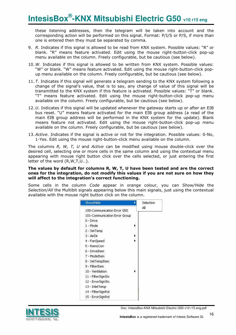
Some cells in the column Code appear in orange colour, you can Show/Hide the
Selection/All the Multibit signals appearing below this main signals, just using the contextual
available with the mouse right button click on the column.

IntesisBox®-KNX Mitsubishi Electric G50 v10 r15 eng
Doc: IntesisBox-KNX Mitsubishi Electric G50 v10 r15 eng.pdf
17IntesisBox is a registered trademark of Intesis Software SL
If you select Show/Hide Selection, new signals appear or disappear under the main signal.
These new signals are the Multibit signals, and are for the following use. For main signals
which may vary between a reduced number of values, for example, 0-1-2-3-4, this signal
can be used with EIS6 (Value 8bits), but can be also necessary or convenient actuate on it
using simpler objects as for example a switch EIS1 (switching). The new Multibit signals (in
yellow colour) appearing just below these main signals can be used for this, using simple
EIS1 objects. Show/Hide Selection can be also performed using mouse double-click over the
orange cells.
Show/Hide All affects to all the orange cells in the grid.
Take into account that, although the Multibit signals are showed, they will not be used until
they are active (Active:1-Yes).
The figure below shows the signals table with Multibit signals Hide.
IntesisBox®-KNX Mitsubishi Electric G50 v10 r15 eng
Doc: IntesisBox-KNX Mitsubishi Electric G50 v10 r15 eng.pdf
18IntesisBox is a registered trademark of Intesis Software SL
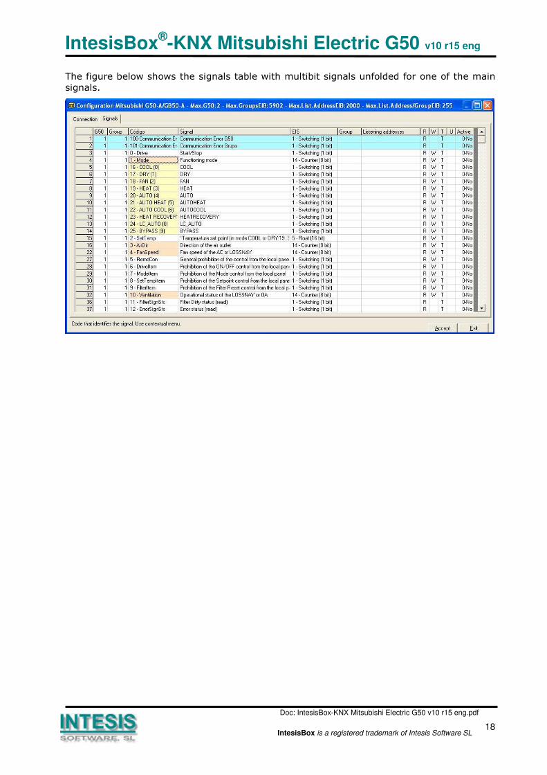
The figure below shows the signals table with multibit signals unfolded for one of the main
signals.
IntesisBox®-KNX Mitsubishi Electric G50 v10 r15 eng
Doc: IntesisBox-KNX Mitsubishi Electric G50 v10 r15 eng.pdf
19IntesisBox is a registered trademark of Intesis Software SL
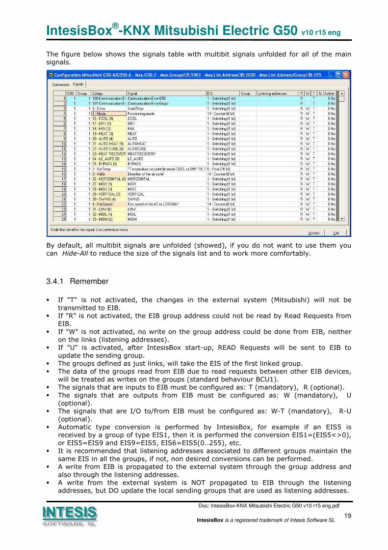
The figure below shows the signals table with multibit signals unfolded for all of the main
signals.
By default, all multibit signals are unfolded (showed), if you do not want to use them you
can Hide-All to reduce the size of the signals list and to work more comfortably.
3.4.1 Remember
� If "T" is not activated, the changes in the external system (Mitsubishi) will not be
transmitted to EIB.
� If "R" is not activated, the EIB group address could not be read by Read Requests from
EIB.
� If "W" is not activated, no write on the group address could be done from EIB, neither
on the links (listening addresses).
� If "U" is activated, after IntesisBox start-up, READ Requests will be sent to EIB to
update the sending group.
� The groups defined as just links, will take the EIS of the first linked group.
� The data of the groups read from EIB due to read requests between other EIB devices,
will be treated as writes on the groups (standard behaviour BCU1).
� The signals that are inputs to EIB must be configured as: T (mandatory), R (optional).
� The signals that are outputs from EIB must be configured as: W (mandatory), U
(optional).
� The signals that are I/O to/from EIB must be configured as: W-T (mandatory), R-U
(optional).
� Automatic type conversion is performed by IntesisBox, for example if an EIS5 is
received by a group of type EIS1, then it is performed the conversion EIS1=(EIS5<>0),
or EIS5=EIS9 and EIS9=EIS5, EIS6=EIS5(0..255), etc.
� It is recommended that listening addresses associated to different groups maintain the
same EIS in all the groups, if not, non desired conversions can be performed.
� A write from EIB is propagated to the external system through the group address and
also through the listening addresses.
� A write from the external system is NOT propagated to EIB through the listening
addresses, but DO update the local sending groups that are used as listening addresses.

IntesisBox®-KNX Mitsubishi Electric G50 v10 r15 eng
Doc: IntesisBox-KNX Mitsubishi Electric G50 v10 r15 eng.pdf
20IntesisBox is a registered trademark of Intesis Software SL
� If a sending group is used as listening address with other local sending groups, a write
from the external system will update the sending group but not the listening addresses.
� In case of an EIB bus reset, if "UpdateOnResetoErrEIB" is activated in the file
MitsubishiG50.ini (located in the project folder), then it will be forced an update of all
the groups configured as "U" and the status of the external system signals is reset to
force an update in the direction "towards EIB".
3.4.2 Restrictions
� It is allowed group numbers in format P/I/S, P/S or directly the group number coded.
� It is not allowed duplicated sending groups (column Group).
� Group 0 is not allowed, it is used for signals without sending group.
� NO signal is allowed with none of R-W-T-U flags activated.
� Empty groups are allowed, but only if they have just W activated and one or more
listening addresses.
� Duplicated groups in the same listening address field are not allowed.
� It is not allowed a listening address that is the same as the sending group (circular
reference).
� Listening addresses are not allowed if the flag W is not activated. Without W activated,
the listening addresses would not work.
� Only those EIS defined are allowed.
3.4.3 Conventions
� To perform a Filter Reset or an Error Reset of G50 groups, you must write a 1.
� The Multibit properties are executed only writing 1, if a 0 is written, the value (0) will
remain in the sending group but will perform no action.
� If an EIS6 is written for example, any value that is greater than the maximum supported
by the Mitsubishi Electric associated signal will be limited and the maximum permitted
will be used to send to the external system (Mitsubishi Electric).
3.5 Saving the configuration and Sending it to the gateway
When the configuration is finished, click on button Save to save it to the project folder on
hard disk. You will be prompted to generate the configuration file to send to the gateway, if
you select Yes, the binary file containing the configuration for the gateway will be generated
and saved also into the project folder.
Once the configuration has been saved and the configuration file for the gateway has been
generated, to send this configuration file to the gateway, click on the button Send File. The
process of file transmission can be monitored in the IntesisBox Communication Console
window. If the file transmission is ok, IntesisBox will reboot automatically with the new
configuration loaded.
3.6 Signals viewer
Once the gateway is running with the correct configuration, to supervise the status of the
configured signals, select menu View -> Signals. The Signals Viewer window will be opened.
This window shows all the active gateway's signals with its main configuration parameters
and its real time value in the column Value. After a reset of IntesisBox or after sending a

IntesisBox®-KNX Mitsubishi Electric G50 v10 r15 eng
Doc: IntesisBox-KNX Mitsubishi Electric G50 v10 r15 eng.pdf
21IntesisBox is a registered trademark of Intesis Software SL
configuration file to the IntesisBox, all the signal's values will be updated automatically in
the signals viewer, in case you connect to the IntesisBox when it is already running, you
should press the Update button to get updated values, press just once the button to update
all the signal values, from this moment the signal values will be maintained updated until
the connection is closed.
The signals viewer can be used although only one system is connected to the IntesisBox,
EIB or Mitsubishi Electric G50, and is very useful for supervision and test.
It is possible to force a specific value to any signal for test purposes, to do so just double
click on the row and select the desired value and Accept in the Data Test window. If the
signal has W-T activated, its value will be updated a telegram will be sent to EIB indicating
the new value, the same way as if it has been received from Mitsubishi Electric G50. If the
signal has W activated, the new value entered will be sent to the external system,
Mitsubishi Electric G50 in this case, the same way as if it has been received from EIB.
This tool is very useful to test any of the systems connected to IntesisBox, EIB and
Mitsubishi Electric G50 without the need to actuate on the real signals.
The signals viewer window has a button to copy to the Windows Clipboard all the contents
of the window (in tab separated text format).
IntesisBox®-KNX Mitsubishi Electric G50 v10 r15 eng
Doc: IntesisBox-KNX Mitsubishi Electric G50 v10 r15 eng.pdf
22IntesisBox is a registered trademark of Intesis Software SL
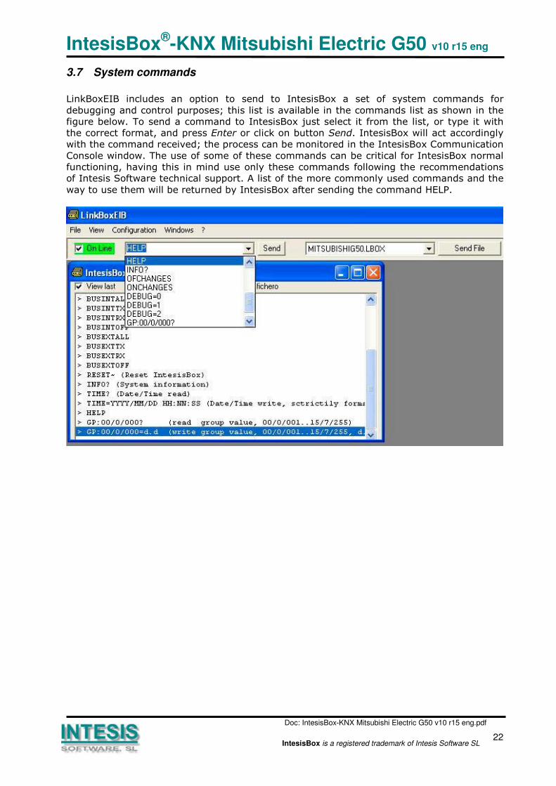
3.7 System commands
LinkBoxEIB includes an option to send to IntesisBox a set of system commands for
debugging and control purposes; this list is available in the commands list as shown in the
figure below. To send a command to IntesisBox just select it from the list, or type it with
the correct format, and press Enter or click on button Send. IntesisBox will act accordingly
with the command received; the process can be monitored in the IntesisBox Communication
Console window. The use of some of these commands can be critical for IntesisBox normal
functioning, having this in mind use only these commands following the recommendations
of Intesis Software technical support. A list of the more commonly used commands and the
way to use them will be returned by IntesisBox after sending the command HELP.

IntesisBox®-KNX Mitsubishi Electric G50 v10 r15 eng
Doc: IntesisBox-KNX Mitsubishi Electric G50 v10 r15 eng.pdf
23IntesisBox is a registered trademark of Intesis Software SL
3.8 Files
LinkBoxEIB saves the gateway configuration in the following files inside the project folder:
PROJECT.INI Ini file containing general information referent to the project
MITSUBISHIG50.INI Ini file containing the information referent to the connection
window and other special adjustments
MITSUBISHIG50.DAT Text file (tab separated values) with the signals information
(signals list). This file can be edited (with Excel for example) to
change the configuration quicker and easier. Later on, when
selecting Configuration -> IntesisBox in LinkBoxEIB, if the changes
have been made respecting the correct format, all the changes in
the configuration done from Excel can be seen in the signals list.
MITSUBISHIG50.LBOX Binary file created from the information in the files described
above. This is the file uploaded to the gateway.
It is strongly recommended to back up the project folder containing these files in external
media, once the installation process is finished. This way you will be able to do future
configuration changes in case of reinstallation of LinkBoxEIB due, for example, to a failure
of the hard disk in the PC where LinkBoxEIB was previously installed.
The configuration cannot be downloaded from the gateway to LinkBoxEIB, only
can be uploaded; the upload file MITSUBISHIG50.LBOX does not contain all the
integration information, as for example the signals description.
The following adjustment variables can be found in the file MITSUBISHIG50.INI :
[MitsubishiG50]
TmConnectG50_s=10 G50 connection waiting time (seconds)
TmResponseG50_s=10 G50 response waiting time (seconds)
TmPolling_ms=1000 G50 polling cadence (milliseconds)
[EIB]
tS_ChekEIB=60 EIB coupler supervision cadence (seconds)
tMS_WaitUpdate=2000 Response waiting time for Read requests (millisec)
tMS_WaitInConect=6000 Waiting time in Connect status (millisec)
UpdateOnResetoErrEIB=1 If =1, after an EIB bus reset, the same process as when
starting-up will be performed.
Important. Do not modify these variables if you are not sure about the effects it
will have, entering incorrect values may lead to malfunctions of IntesisBox.

IntesisBox®-KNX Mitsubishi Electric G50 v10 r15 eng
Doc: IntesisBox-KNX Mitsubishi Electric G50 v10 r15 eng.pdf
24IntesisBox is a registered trademark of Intesis Software SL
4. Setup process and troubleshooting
4.1 Pre-requisites
It is necessary to have a KNX TP-1 (EIB) system operative and ready to be connected to the
EIB port of IntesisBox.
It is necessary to have an Ethernet 10BT network connection near IntesisBox (network hub
or switch port) with all Mitsubishi Electric G50 devices connected to this Ethernet network.
Connectors, connection cables, PC for LinkBoxEIB, and network hub or switch are not
supplied by Intesis Software for this standard integration. The items supplied by Intesis
Software for this integration are:
• IntesisBox-KNX gateway with KNX internal protocol and Mitsubishi Electric G50 external
protocol firmware loaded.
• Console cable. Standard DB9F-DB9M cable 1.8 meters long.
• LinkBoxEIB software.
• Product documentation.
4.2 Setup procedure
1. Install LinkBoxEIB on your laptop.
2. Install IntesisBox in the desired installation site. The mounting can be on DIN rail or
on a stable not vibrating surface (DIN rail mounting inside a metallic industrial
cabinet connected to ground is recommended).
3. Connect the KNX TP-1 (EIB) bus cable to the port marked as KNX TP-1 (EIB) of
IntesisBox. (See details for this bus cable in section Connections of this document).
4. Connect the communication cable coming from the network hub or switch to the port
marked as ETH of IntesisBox. (See details for this communication cable in section
Connections of this document).
5. Power up IntesisBox using a standard power supply 220/125VAC-12VDC/300mA for
example.
WARNING! In order to avoid earth loops that can damage the gateway and/or any
other equipment connected to it, we strongly recommend:
• The use of DC power supplies, floating or with the negative terminal connected to
earth. Never use a DC power supply with the positive terminal connected
to earth.
• The use of AC power supplies only if they are floating and not powering any other
device.
6. Connect the communication cable coming from the serial port of your laptop PC to
the port marked as PC of IntesisBox. (See details for this communication cable in
section Connections of this document).
7. Open LinkBoxEIB, create a new project selecting a copy of the one named DEMO
Mitsubishi and give it the name desired, select the serial port used to connect to

IntesisBox®-KNX Mitsubishi Electric G50 v10 r15 eng
Doc: IntesisBox-KNX Mitsubishi Electric G50 v10 r15 eng.pdf
25IntesisBox is a registered trademark of Intesis Software SL
IntesisBox (menu Configuration -> Connection) and switch working mode to on-line
(checkbox off-line/on-line). The IntesisBox identification must appear in the
IntesisBox communication console window as showed below.
8. Open the EIB Communication Viewer window (menu View -> Bus -> EIB) and check
that there is communication activity, some TX frames and some other rx frames.
This means that the communication with the KNX system is ok. In case there is no
communication activity between IntesisBox and the KNX system check that EIB bus
is operative and well connected to the IntesisBox.
9. Open the External Protocol Communication Viewer window (menu View -> Bus ->
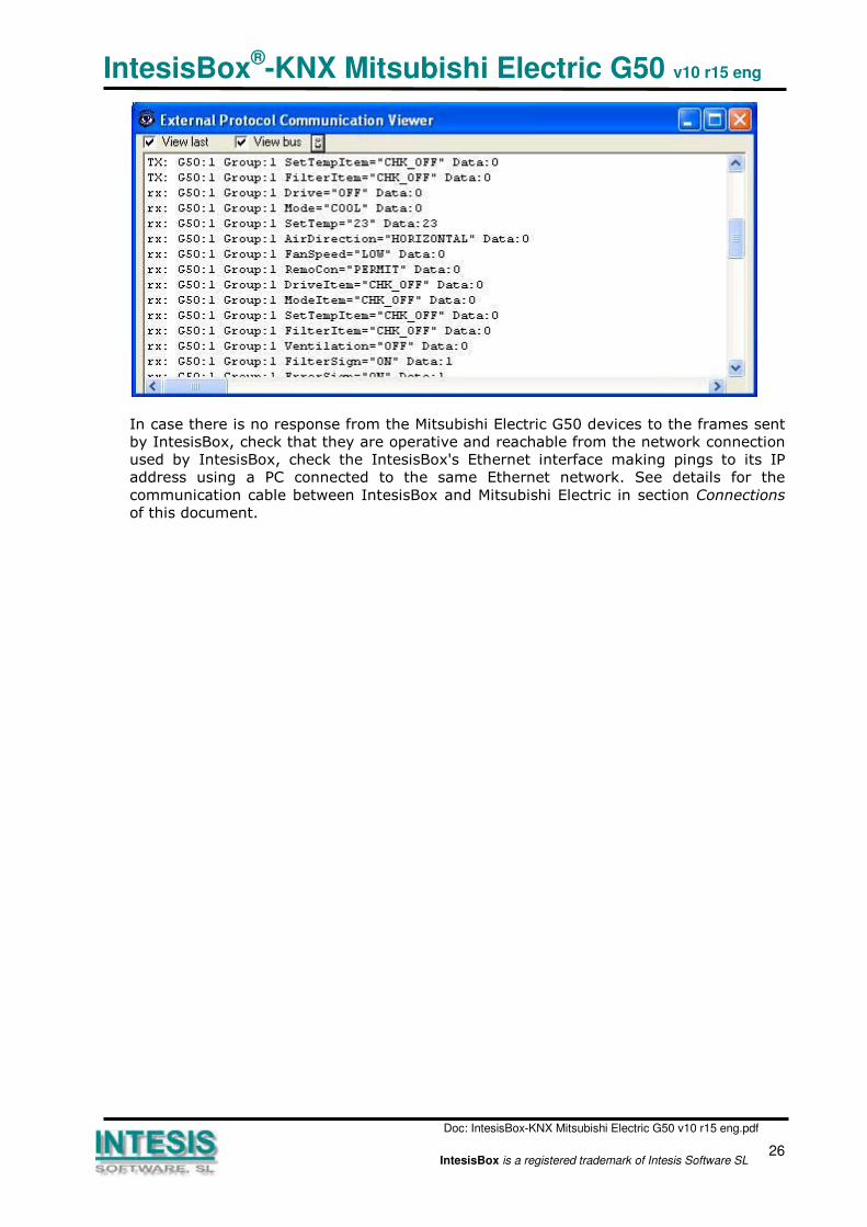
External system) and check that there is communication activity, some TX frames
and some other rx frames as showed in the figure below. This means that the
communication with the Mitsubishi Electric system is ok.
IntesisBox®-KNX Mitsubishi Electric G50 v10 r15 eng
Doc: IntesisBox-KNX Mitsubishi Electric G50 v10 r15 eng.pdf
26IntesisBox is a registered trademark of Intesis Software SL
In case there is no response from the Mitsubishi Electric G50 devices to the frames sent
by IntesisBox, check that they are operative and reachable from the network connection
used by IntesisBox, check the IntesisBox's Ethernet interface making pings to its IP
address using a PC connected to the same Ethernet network. See details for the
communication cable between IntesisBox and Mitsubishi Electric in section Connections
of this document.
IntesisBox®-KNX Mitsubishi Electric G50 v10 r15 eng
Doc: IntesisBox-KNX Mitsubishi Electric G50 v10 r15 eng.pdf
27IntesisBox is a registered trademark of Intesis Software SL
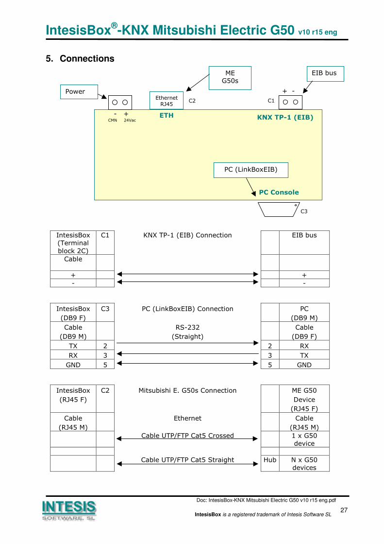
5. Connections
IntesisBox
(Terminal
block 2C)
C1 KNX TP-1 (EIB) Connection EIB bus
Cable
+ +
- -
IntesisBox
(DB9 F)
C3 PC (LinkBoxEIB) Connection PC
(DB9 M)
Cable
(DB9 M)
RS-232
(Straight)
Cable
(DB9 F)
TX 2 2 RX
RX 3 3 TX
GND 5 5 GND
IntesisBox
(RJ45 F)
C2 Mitsubishi E. G50s Connection ME G50
Device
(RJ45 F)
Cable
(RJ45 M)
Ethernet Cable
(RJ45 M)
Cable UTP/FTP Cat5 Crossed 1 x G50
device
Cable UTP/FTP Cat5 Straight Hub N x G50
devices
C1C2
C3
EthernetRJ45
KNX TP-1 (EIB)
PC Console
ETH
PC (LinkBoxEIB)
+ -
EIB busMEG50s
- +CMN 24Vac
Power
IntesisBox®-KNX Mitsubishi Electric G50 v10 r15 eng
Doc: IntesisBox-KNX Mitsubishi Electric G50 v10 r15 eng.pdf
28IntesisBox is a registered trademark of Intesis Software SL
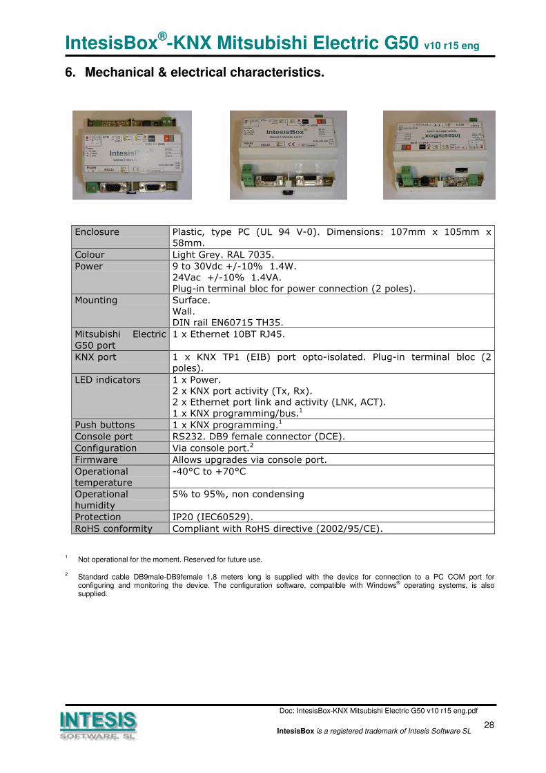
6. Mechanical & electrical characteristics.
Enclosure Plastic, type PC (UL 94 V-0). Dimensions: 107mm x 105mm x
58mm.
Colour Light Grey. RAL 7035.
Power 9 to 30Vdc +/-10% 1.4W.
24Vac +/-10% 1.4VA.
Plug-in terminal bloc for power connection (2 poles).
Mounting Surface.
Wall.
DIN rail EN60715 TH35.
Mitsubishi Electric
G50 port
1 x Ethernet 10BT RJ45.
KNX port 1 x KNX TP1 (EIB) port opto-isolated. Plug-in terminal bloc (2
poles).
LED indicators 1 x Power.
2 x KNX port activity (Tx, Rx).
2 x Ethernet port link and activity (LNK, ACT).
1 x KNX programming/bus.1
Push buttons 1 x KNX programming.1
Console port RS232. DB9 female connector (DCE).
Configuration Via console port.2
Firmware Allows upgrades via console port.
Operational
temperature
-40°C to +70°C
Operational
humidity
5% to 95%, non condensing
Protection IP20 (IEC60529).
RoHS conformity Compliant with RoHS directive (2002/95/CE).
1Not operational for the moment. Reserved for future use.
2Standard cable DB9male-DB9female 1,8 meters long is supplied with the device for connection to a PC COM port forconfiguring and monitoring the device. The configuration software, compatible with Windows
® operating systems, is also
supplied.
IntesisBox®-KNX Mitsubishi Electric G50 v10 r15 eng
Doc: IntesisBox-KNX Mitsubishi Electric G50 v10 r15 eng.pdf
29IntesisBox is a registered trademark of Intesis Software SL
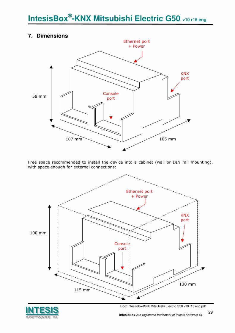
7. Dimensions
Free space recommended to install the device into a cabinet (wall or DIN rail mounting),
with space enough for external connections:
Ethernet port
+ Power
107 mm 105 mm
58 mm
KNXport
Consoleport
Ethernet port
+ Power
115 mm
130 mm
100 mm
KNXport
Consoleport

IntesisBox®-KNX Mitsubishi Electric G50 v10 r15 eng
Doc: IntesisBox-KNX Mitsubishi Electric G50 v10 r15 eng.pdf
30IntesisBox is a registered trademark of Intesis Software SL
8. Annexes
8.1 Gateways Mitsubishi Electric G-50A and GB-50A.
G-50A
GB-50A
For more information about these devices, contact your nearest Mitsubishi Electric dealer.