interrupts - webcms3...⚫ resume normal programmed task. 4 recognize interrupt events ... ⚫ wait...
TRANSCRIPT

1
Interrupts
Lecturer: Sri Parameswaran
Notes by: Annie Guo

2
CPU Interacts with I/O
Two approaches:
⚫ Polling
⚫ Software queries I/O devices.
⚫ No extra hardware needed.
⚫ Not efficient.
⚫ CPU may waste processor cycles to query a device even if it
does not need any service.
⚫ Interrupts
⚫ I/O devices generate signals to request services from CPU .
⚫ Need special hardware to implement interrupt services.
⚫ Efficient.
⚫ A signal is generated only if the I/O device needs services from
CPU.
3
Interrupt Systems
⚫ An interrupt system implements interrupt
services
⚫ It basically performs three tasks:
⚫ Recognize interrupt events
⚫ Respond to the interrupts
⚫ Resume normal programmed task

4
Recognize Interrupt Events
⚫ Interrupt events
⚫ Associated with interrupt signals:
⚫ In different forms, including levels and edges.
⚫ Can be multiple and synchronous
⚫ Namely, there may be many sources to generate an
interrupts; a number of interrupts can be generated at
the same time.
⚫ Approaches are required to:
⚫ Identify an interrupt event among multiple sources
⚫ Determine which interrupts to serve if there are
multiple simultaneous interrupts

5
Respond to Interrupts
⚫ Handling interrupt
⚫ Wait for the current instruction to finish.
⚫ Acknowledge the interrupting device.
⚫ Branch to the correct interrupt service routine
(interrupt handler) to service interrupting device.
6
Resume Normal Task
⚫ Return to the interrupted program at the point
it was interrupted.

7
Interrupt Process Control
⚫ Interrupts can be enabled or disabled
⚫ Can be controlled in two ways:
⚫ Software control
⚫ Allow programmers to enable and disable selected/all
interrupts.
⚫ Hardware control
⚫ Disable further interrupts while an interrupt is being
serviced
8
Transferring Control to
Interrupt Service Routine
⚫ Hardware needs to save the return address.⚫ Most processors save the return address on the stack.
⚫ Hardware may also save some registers such as program status register. ⚫ AVR does not save any registers. It is the programmers’
responsibility to save the program status register and conflict registers.
⚫ The delay from the time the IRQ is generated by the interrupting device to the time the Interrupt Service Routine (ISR) starts to execute is called interrupt latency.

9
Interrupt Service Routine
⚫ A sequence of code to be executed when the corresponding interrupt is responded by CPU.
⚫ Interrupt service routine is a special subroutine, therefore can be constructed with three parts:⚫ Prologue:
⚫ Code for saving conflict registers on the stack.
⚫ Body:
⚫ Code for doing the required task.
⚫ Epilogue:
⚫ Code for restoring all saved registers from the stack.
⚫ The last instruction is the return-from-interrupt instruction.

10
Software Interrupt
⚫ Software interrupt is the interrupt generated by
software without a hardware-generated-IRQ.
⚫ Software interrupt is typically used to implement
system calls in OS.
⚫ Some processors have a special machine
instruction to generate software interrupt.
⚫ SWI in ARM.
⚫ AVR does NOT provide a software interrupt
instruction.
⚫ Programmers can use External Interrupts to implement
software interrupts.

11
Exceptions
⚫ Abnormalities that occur during the normal
operation of the processor.
⚫ Examples are internal bus error, memory access
error and attempts to execute illegal instructions.
⚫ Some processors handle exceptions in the
same way as interrupts.
⚫ AVR does not handle exceptions.
12
Reset
⚫ Reset is a type of interrupt present in most
processors (including AVR).
⚫ Non-maskable.
⚫ It does not do other interrupt processes, such
as saving conflict registers. It initializes the
system to some initial state.

13
AVR Interrupts⚫ Basically can be divided into internal and external
interrupts
⚫ Each has a dedicated interrupt vector
⚫ Hardware is used to recognize interrupts
⚫ To enable an interrupt, two control bits must be set⚫ the Global Interrupt Enable bit (I bit) in the Status Register
⚫ Using sei
⚫ the enable bit for that interrupt
⚫ To disable all maskable interrupts, reset the I bit in SREG⚫ Using cli instruction
⚫ Priority of interrupts is used to handle multiple simultaneous interrupts

14
Set Global Interrupt Flag
⚫ Syntax: sei
⚫ Operands: none
⚫ Operation: I 1.
⚫ Sets the global interrupt flag (I) in SREG. The instruction following SEI will be executed before any pending interrupts.
⚫ Words: 1
⚫ Cycles: 1
⚫ Example:sei ; set global interrupt enable
sleep ; enter sleep state, waiting for an interrupt

15
Clear Global Interrupt Flag⚫ Syntax: cli
⚫ Operands: none
⚫ Operation: I 0
⚫ Clears the Global interrupt flag in SREG. Interrupts will be immediately disabled.
⚫ Words: 1
⚫ Cycles: 1
⚫ Example:in r18, SREG ; store SREG value
cli ; disable interrupts
; do something very important here
out SREG, r18 ; restore SREG value

16
Interrupt Response Time
⚫ The interrupt execution response for all the
enabled AVR interrupts is basically five clock
cycles minimum.
⚫ For saving the Program Counter (2 clock cycles)
⚫ For jumping to the interrupt routine (3 clock
cycles)

17
Interrupt Vectors
⚫ Each interrupt has a 4-byte (2-word) interrupt vector,
containing an instruction to be executed after MCU
has accepted the interrupt.
⚫ The lowest addresses in the program memory space
are by default defined as the section for Interrupt
Vectors.
⚫ The priority of an interrupt is based on the position
of its vector in the program memory
⚫ The lower the address the higher is the priority level.
⚫ RESET has the highest priority

18
Interrupt Vectors in Mega2560

19
Interrupt Vectors in Mega2560
(cont.)

20
Interrupt Vectors in Mega2560
(cont.)

21
Interrupt Vectors in Mega2560
(cont.)

22
Interrupt Process
⚫ When an interrupt occurs, the Global Interrupt
Enable I-bit is cleared and all interrupts are disabled.
⚫ The interrupt routine can set the I-bit to allow nested
interrupts
⚫ The I-bit is automatically set when a Return from
Interrupt instruction – RETI – is executed.
⚫ When the AVR exits from an interrupt, it will always
return to the main program and execute one more
instruction before any pending interrupt is served.
⚫ Reset interrupt is an exception

23
Initialization of Interrupt Vector
Table in Mega2560
⚫ Typically an interrupt vector contains a
branch instruction (JMP or RJMP) that
branches to the first instruction of the
interrupt service routine.
⚫ Or simply RETI (return-from-interrupt) if you
don’t handle this interrupt.

24
Example of IVT Initialization in
Mega2560
.include "m2560def.inc"
.cseg
.org 0x0000 ; Reset vector is at address 0x0000
rjmp RESET ; Jump to the start of Reset interrupt service routine
; Relative jump is used assuming RESET is not far
.org INT0addr ; Addresses of vectors are defined in m2560def.inc
jmp IRQ0 ; Long jump is used assuming IRQ0 is very far away
.org INT1addr
reti ; Return to the break point without handling the interrupt
…
RESET: ; The interrupt service routine for RESET starts here.
…
IRQ0: ; The interrupt service routine for IRQ0 starts here.

25

26
External Interrupts
⚫ The external interrupts are triggered by the
INT7:0 pins.
⚫ If enabled, the interrupts will trigger even if the
INT7:0 are configured as outputs
⚫ This feature provides a way of generating a software
interrupt.
⚫ Can be triggered by a falling or rising edge or a
logic level
⚫ Specified in External Interrupt Control Register
▪ EICRA (for INT3:0)
▪ EICRB (for INT7:4)

27
External Interrupts (cont.)
⚫ To enable an interrupt, two bits must be set
⚫ I bit in SREG
⚫ INTx bit in EIMSK
⚫ To activate an interrupt, the following must be
met:
⚫ The interrupt must be enabled
⚫ The associated external pin must have a
designed signal asserted.
28
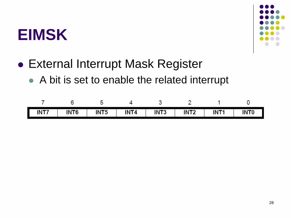
EIMSK
⚫ External Interrupt Mask Register
⚫ A bit is set to enable the related interrupt

29
EICRA⚫ External Interrupt Control Register A
⚫ For INT0-3
⚫ Defines the type of signals that activates the external
Interrupt
⚫ on rising or falling edge or level sensed.
30
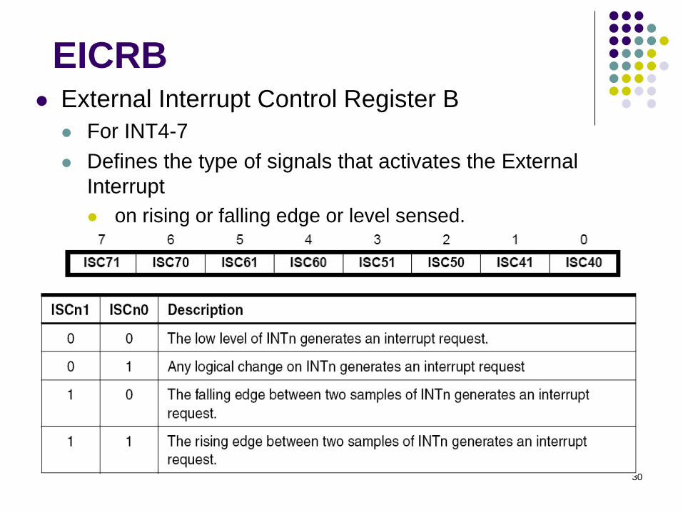
EICRB⚫ External Interrupt Control Register B
⚫ For INT4-7
⚫ Defines the type of signals that activates the External
Interrupt
⚫ on rising or falling edge or level sensed.

31
EIFR
⚫ Interrupt flag register
⚫ A bit is set when an event-triggered interrupt is
enabled and the related event on the related INT
pin happens.
⚫ Event-triggered interrupt: signal edge activated.

32
Example 1
⚫ Design a system, where the state of LEDs
toggles under the control of the user.

33
Example 1 (solution)
⚫ Use an external interrupt
⚫ Connect the external interrupt pin to a push button
⚫ When the button pressed, the interrupt is generated
⚫ In the assembly code
⚫ Set up the interrupt
⚫ Set up the interrupt vector
⚫ Enable the interrupt
⚫ Write a service routine for this interrupt
⚫ Change the display pattern
⚫ Write the pattern to the port connected to the LEDs

34
Code for Example 1.include "m2560def.inc“
.def temp =r16
.def output = r17
.def count = r18
.equ PATTERN = 0b01010101
; set up interrupt vectorsjmp RESET
.org INT0addrjmp EXT_INT0
RESET:ldi temp, low(RAMEND) ; initialize stackout SPL, templdi temp, high(RAMEND)out SPH, temp
ser temp ; set Port C as outputout DDRC, tempout PORTC, templdi output, PATTERN
; continued
35
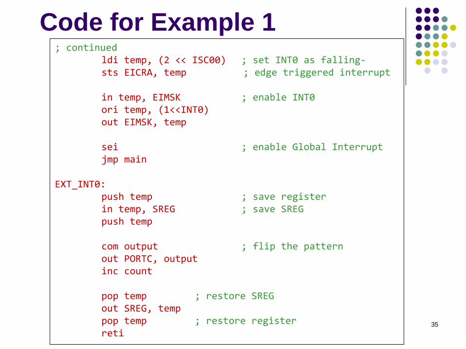
Code for Example 1; continued
ldi temp, (2 << ISC00) ; set INT0 as falling-sts EICRA, temp ; edge triggered interrupt
in temp, EIMSK ; enable INT0ori temp, (1<<INT0)out EIMSK, temp
sei ; enable Global Interruptjmp main
EXT_INT0:push temp ; save registerin temp, SREG ; save SREGpush temp
com output ; flip the patternout PORTC, outputinc count
pop temp ; restore SREGout SREG, temppop temp ; restore registerreti

36
Code for Example 1; continued
; main - does nothing but increment a countermain:
clr countclr temp
loop:inc temp ; a dummy task in mainrjmp loop

37
Timer/Counters
⚫ Simply binary counters
⚫ Used in two different modes:⚫ Timer
⚫ Counting time periods
⚫ Counter
⚫ Counting the events or pulse or something of this nature
⚫ Can be used to⚫ Measure time periods, speed, frequency
⚫ Generate PWM signals
⚫ Schedule real-time tasks
⚫ etc.

38
Timer/Counters in AVR
⚫ In AVR, there are 8-bit and 16-bit
timer/counters.
⚫ Timer 0 and Timer 2: 8-bit
⚫ Timer 1,3-5 16-bit
39
8-bit Timer/Counter Block
Diagram

40
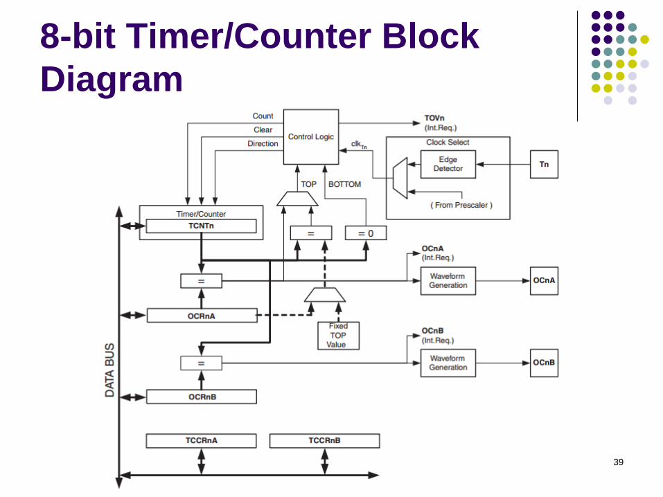
8-bit Timer/Counter
⚫ The counter can be initialized with
⚫ 0 (controlled by reset)
⚫ a number (controlled by count signal)
⚫ Can count up or down
⚫ controlled by direction signal
⚫ Those controlled signals are generated by hardware control logic
⚫ The control logic is further controlled by programmer by
⚫ Writing control bits into TCCRnA/TCCRnB
⚫ Output
⚫ Overflow interrupt request bit
⚫ Output Compare interrupt request bit
⚫ OCn bit: Output Compare bit for waveform generation
41
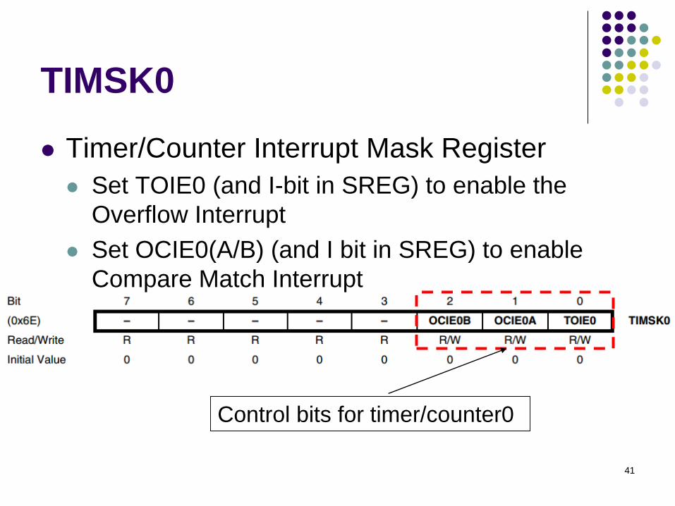
TIMSK0
⚫ Timer/Counter Interrupt Mask Register
⚫ Set TOIE0 (and I-bit in SREG) to enable the
Overflow Interrupt
⚫ Set OCIE0(A/B) (and I bit in SREG) to enable
Compare Match Interrupt
Control bits for timer/counter0
42
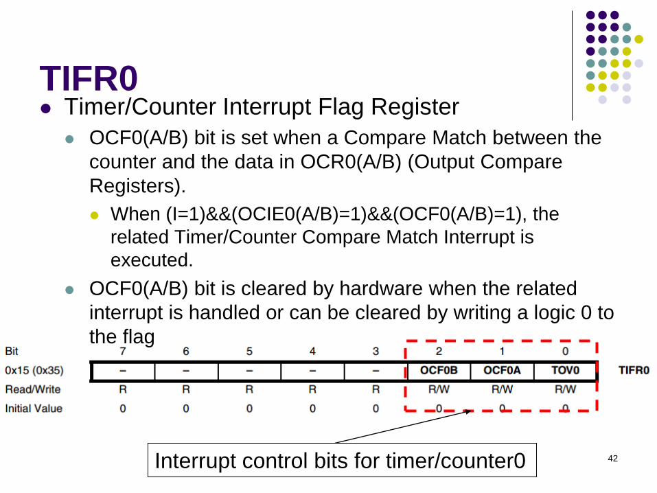
TIFR0⚫ Timer/Counter Interrupt Flag Register
⚫ OCF0(A/B) bit is set when a Compare Match between the
counter and the data in OCR0(A/B) (Output Compare
Registers).
⚫ When (I=1)&&(OCIE0(A/B)=1)&&(OCF0(A/B)=1), the
related Timer/Counter Compare Match Interrupt is
executed.
⚫ OCF0(A/B) bit is cleared by hardware when the related
interrupt is handled or can be cleared by writing a logic 0 to
the flag
Interrupt control bits for timer/counter0

43
TIFR0 (cont.)⚫ Timer/Counter Interrupt Flag Register
⚫ TOV0 bit is set when an overflow occurs in the counter.
⚫ When (I=1)&&(TOIE0=1)&&(TOV0=1), the related
Timer/Counter Overflow Interrupt is executed.
⚫ In PWM mode, this bit is set when the counter changes
counting direction at 0x00
⚫ OCF0(A/B) bit is cleared by hardware when the related
interrupt is handled or can be cleared by writing a logic 0 to
the flag
Interrupt control bits for timer/counter0

44
TCCR0A/B
⚫ Timer Counter Control Register
⚫ For Timer/Counter0
⚫ Similar registers for other timers

45
TCCR0 Bit Description
⚫ COM0xn/WGM0n/FOC0
⚫ Control the mode of operation
⚫ The behavior of the Timer/Counter and the output, is defined by
the combination of the Waveform Generation mode (WGM02:00)
and Compare Output mode (COM0x1:0) bits.
⚫ The simplest mode of operation is the Normal Mode (WGM02:00
=00). In this mode the counting direction is always up. The
counter rolls over when it passes its maximum 8-bit value (TOP =
0xFF) and then restarts from the bottom (0x00).
⚫ Refer to Mega2560 Data Sheet (pages 118~194) for details.

46
TCCR0 Bit Description (cont.)⚫ Bit 2:0 in TCCR0B
⚫ Control the clock selection

47
Example 2
⚫ Implement a scheduler that can execute a
task every one second.

48
Example 2 (solution)
⚫ Use Timer0 to count the time
⚫ Let’s set Timer0 prescaler to 8
⚫ The time-out for the setting should be▪ 256*(clock period) = 256*8/(16 MHz)
= 128 us
▪ Namely, we can set the Timer0 overflow interrupt that is to occur every 128 us.
▪ Note, Clktos = 1/16 MHz (obtained from the data sheet)
⚫ For one second, there are ▪ 1000000/128 = ~7812 interrupts
⚫ In code,
⚫ Set Timer0 interrupt to occur every 128 microseconds
⚫ Use a counter to count to 7812 interrupts for counting 1 second
⚫ To observe the 1 second time period, toggle an LED every second.

49
Example 3; This program implements a timer that counts one second using
; Timer0 interrupt
.include "m2560def.inc"
.equ PATTERN = 0b11110000
.def temp = r16
.def leds = r17
; The macro clears a word (2 bytes) in a memory
; the parameter @0 is the memory address for that word
.macro clear
ldi YL, low(@0) ; load the memory address to Y
ldi YH, high(@0)
clr temp
st Y+, temp ; clear the two bytes at @0 in SRAM
st Y, temp
.endmacro
; contined

50
Example 3; continued.dsegSecondCounter:
.byte 2 ; Two-byte counter for counting seconds.TempCounter:
.byte 2 ; Temporary counter. Used to determine ; if one second has passed
.cseg
.org 0x0000 jmp RESET jmp DEFAULT ; No handling for IRQ0.jmp DEFAULT ; No handling for IRQ1.
.org OVF0addrjmp Timer0OVF ; Jump to the interrupt handler for
; Timer0 overflow.…jmp DEFAULT ; default service for all other interrupts.
DEFAULT: reti ; no service; continued

51
Example 3
; continued
RESET: ldi temp, high(RAMEND) ; Initialize stack pointer
out SPH, temp
ldi temp, low(RAMEND)
out SPL, temp
ser temp ; set Port C as output
out DDRC, temp
rjmp main
; continued

52
Example 3
; continued
Timer0OVF: ; interrupt subroutine to Timer0
in temp, SREG
push temp ; Prologue starts.
push YH ; Save all conflict registers in the prologue.
push YL
push r25
push r24 ; Prologue ends.
; Load the value of the temporary counter.
lds r24, TempCounter
lds r25, TempCounter+1
adiw r25:r24, 1 ; Increase the temporary counter by one.
; continued

53
Example 3
cpi r24, low(7812) ; Check if (r25:r24) = 7812
ldi temp, high(7812) ; 7812 = 106/128
cpc r25, temp
brne NotSecond
com leds
out PORTC, leds
clear TempCounter ; Reset the temporary counter.
; Load the value of the second counter.
lds r24, SecondCounter
lds r25, SecondCounter+1
adiw r25:r24, 1 ; Increase the second counter by one.
; continued

54
Example 3sts SecondCounter, r24
sts SecondCounter+1, r25
rjmp EndIF
NotSecond:
; Store the new value of the temporary counter.
sts TempCounter, r24
sts TempCounter+1, r25
EndIF:
pop r24 ; Epilogue starts;
pop r25 ; Restore all conflict registers from the stack.
pop YL
pop YH
pop temp
out SREG, temp
reti ; Return from the interrupt.; continued

55
Example 3
main:
ldi leds, 0xFF
out PORTC, leds
ldi leds, PATTERN
clear TempCounter ; Initialize the temporary counter to 0
clear SecondCounter ; Initialize the second counter to 0
ldi temp, 0b00000000
out TCCR0A, temp
ldi temp, 0b00000010
out TCCR0B, temp ; Prescaling value=8
ldi temp, 1<<TOIE0 ; = 128 microseconds
sts TIMSK0, temp ; T/C0 interrupt enable
sei ; Enable global interrupt
loop: rjmp loop ; loop forever

56
Reading Material
⚫ Chapter 8: Interrupts and Real-Time Events.
Microcontrollers and Microcomputers by
Fredrick M. Cady.
⚫ Mega2560 Data Sheet.
⚫ External Interrupts.
⚫ Timer0

57
Homework
1. What do you need to do to set up an Timer0
Output Compare Match Interrupt?

58
Homework
2. Based on the Example 1 in this week lecture
slides, implement a software interrupt such
that when there is an overflow in the counter
that counts the number of LED toggles, all
LEDs are turned on.