interruptores de levas cam switches - mercado-ideal.com interruptores de … · interruptores de...
TRANSCRIPT

Interruptoresde levas
Cam switches

INTERRUPTORES DE LEVAS / CAM SWITCHES
2
INTERRUPTORES DE LEVAS / CAM SWITCHES
3
INTERRUPTORES DE LEVAS / CAM SWITCHES

INTERRUPTORES DE LEVAS / CAM SWITCHES
5
PanorámicaOverview
Presentamos una moderna y amplia gama de interruptores de levas con un diseño renovado, bornes protegidos amovibles, gran variedad de accesorios, y unos mandos ergonómicos de estética muy actual provistos de indicador de posición.
Están fabricados de acuerdo con las normas IEC 60947-3, UNE-EN 60947-3, CSA 22.2-14, UL 508, RoHS, bajo estrictos contro-les de calidad, para ofrecer un producto fi able que satisfaga las necesidades más exigentes.
Se componen de cámaras (pisos) que alojan en cada una dos contactos de doble ruptura y apertura positiva. Dichos contactos están revestidos de una aleación de plata que les proporcionan de esta forma una larga vida mecánica. Los bornes de conexión van provistos de tornillos con abrazade-ra cautiva para facilitar el trabajo de instalación, y todas las conexiones propias están cubiertas para ofrecer un grado de protección IP20.
Permiten seleccionar hasta 34 posiciones y maniobrar hasta 72 contactos al mismo tiempo, obteniendo un número muy elevado de combinaciones de contactos, por lo que aportan soluciones fl exibles y rápidas a un coste muy favorable.
Telergón presents its wide range of cam switches with a new updated design, a complete range of accessories, re-movable terminal protection IP20 and ergonomic handles with position indicator.
The whole range is manufactured according to IEC 60947-3, UNE-EN 60947-3, CSA 22.2-14, UL 508 standards and in compliance with RoHS directive, under strict quality con-trols, in order to offer reliable products and to meet most demanding customer’s requirements.
Their structure is based in switching chambers with two cam operated contacts. Each contact is silver alloy plat-ed and provides an exceptionally long mechanical life.Connection terminals are provided with captive wire clamp screws, in order to install the switches easier. All con-nections are covered in order to offer an IP20 protectiondegree.
They allow to select up to 34 positions and switching up to 72 contacts at the same time, so Telergón’s switches bring flexible and fast solutions with advantageous costs for the client.
Interruptores para instalaciones en circuitos principales. Interruptores para instalaciones en circuitos de control.Auxiliares en cuadros de distribución.Centros de control de motores.Interruptores de seguridad y/o emergencia.Instalaciones de energías alternativas.Cuadros de conmutadores.Arrancadores estrella-triángulo.Inversores de marcha.Conmutadores de velocidades.Conmutadores de voltímetro y amperímetro.Conmutadores BCD.Así como una gran variedad de aplicaciones y esque-mas especiales para resolver múltiples necesidades.
On-Off switches for main circuitsOn-Off switches for control circuitsAuxiliary switches in distribution boardsMotor control centresSafety and/or emergency switchesAlternative energy installations (UPS, Generators)Changeover switchboards Start Delta switchesReversing switchesMulti-step switchesVoltmeter and ammeter switchesSwitches for B.C.D. codifi cationWide range of standard and special diagrams able to solve much of customer’s requirements
Applications:Aplicaciones:
Mando con indicador de posición.Handle with position indicator.
Cubrebornes amovibles (protección IP20).Removable terminal protection (IP20).
001231
TP10 T12, T20 T16, T25, T32, T40 T50, T63, T100 T200... T1600 TF12, TF16, TF25
50 50 65 94 128 50
AmperiosAmpers
CalibreSize
Placa indicadoraIndicating plate
Ith (A)Ith (A)
Potencia de empleo (kW)Rated operational power (kW)Rated operational power (kW)Rated operational power
Ui (V)Ui (V)
25,5... 7,511... 18,530... 45
907,5... 11
500500690690690690
1212... 2516... 50
50... 125125... 1600
12... 32
50 50 65 94 128 50
Composición de la gamaRange scope
ÍndiceIndex
Composición de la gamaRange scope . . . . . . . . . . . . . . . . . . . . . . . . . . . . . . . . . . . . . . . . . . . . . . . . . . . . . . . . . . . . . . . . . . . . . . . . . . . . . . . . . . . . . . . . . . . . . . . . . . . . . . . . . . 4
PanorámicaOverview . . . . . . . . . . . . . . . . . . . . . . . . . . . . . . . . . . . . . . . . . . . . . . . . . . . . . . . . . . . . . . . . . . . . . . . . . . . . . . . . . . . . . . . . . . . . . . . . . . . . . . . . . . . . . . . . . . . 5
Codifi caciónCodes . . . . . . . . . . . . . . . . . . . . . . . . . . . . . . . . . . . . . . . . . . . . . . . . . . . . . . . . . . . . . . . . . . . . . . . . . . . . . . . . . . . . . . . . . . . . . . . . . . . . . . . . . . . . . . . . . . . . . . . . . . . . 6
Formulario interruptores especialesOrder sheet for non-standard cam switches . . . . . . . . . . . . . . . . . . . . . . . . 7
ModelosModels . . . . . . . . . . . . . . . . . . . . . . . . . . . . . . . . . . . . . . . . . . . . . . . . . . . . . . . . . . . . . . . . . . . . . . . . . . . . . . . . . . . . . . . . . . . . . . . . . . . . . . . . . . . . . . . . . . . . . . . . 8
Accesorios y dispositivosAccessories and devices . . . . . . . . . . . . . . . . . . . . . . . . . . . . . . . . . . . . . . . . . . . . . . . . . . . . . . . . . . . . . . . . . . . . . . . . . . 10
Tipos de montajeMounting types . . . . . . . . . . . . . . . . . . . . . . . . . . . . . . . . . . . . . . . . . . . . . . . . . . . . . . . . . . . . . . . . . . . . . . . . . . . . . . . . . . . . . . . . . . . . . . . 16
DimensionesDimensions . . . . . . . . . . . . . . . . . . . . . . . . . . . . . . . . . . . . . . . . . . . . . . . . . . . . . . . . . . . . . . . . . . . . . . . . . . . . . . . . . . . . . . . . . . . . . . . . . . . . . . . . . 20
Diagramas standardStandard diagrams . . . . . . . . . . . . . . . . . . . . . . . . . . . . . . . . . . . . . . . . . . . . . . . . . . . . . . . . . . . . . . . . . . . . . . . . . . . . . . . . . . . . . 27
Características técnicasRating . . . . . . . . . . . . . . . . . . . . . . . . . . . . . . . . . . . . . . . . . . . . . . . . . . . . . . . . . . . . . . . . . . . . . . . . . . . . . . . . . . . . . . . . . . . . . . . . . . . . . . . . . . . . . . 34-35
INTERRUPTORES DE LEVAS / CAM SWITCHES
6 7
Contacto cerradoId. sin interrupciónContacto retrasado
Contacto adelantadoCon retorno a 30º
Contact closedClosed contact without interruptionLate break contactEarly-make contactReturn from 30º
Posiciones Switch positions
Serie Series
FORMULARIO PARA INTERRUPTORES ESPECIALES DE 10 A 200 AMP.ORDER SHEET FOR NON-STANDARD CAM SWITCHES 10 TO 200 AMP.
1
3
5
7
9
11
13
15
17
19
21
23
25
27
29
31
33
35
37
39
41
43
45
47
2
4
6
8
10
12
14
16
18
20
22
24
26
28
30
32
34
36
38
40
42
44
46
48
Conexiones Connections
1 5 9 13 17 21 25 29 33 37 41 45
3 7 11 15 19 23 27 31 35 39 43 47
46 42 38 34 30 26 22 18 14 10 6 2
48 44 40 36 32 28 24 20 16 12 8 4
Tipo Type
Mando Handle Eje prolongaciónShaft extension
mmFlecha / Arrow Negro / Black
Manecilla /Lever handle Rojo / Red
Manecilla de bola /Ball lever handle
Placa indicadora Nameplate
Color aluminio / Aluminium colour
Color amarillo / Yellow colour Con rótulo / With inscription
Cuadrada normal / Normal
Distribución normal / Switching angle 30º - 45º - 60º - 90º
Nº pisos Chambers
Observaciones Notes
Validación Validity
Fecha Date
Firma Signature
Dispositivos especiales Special devices
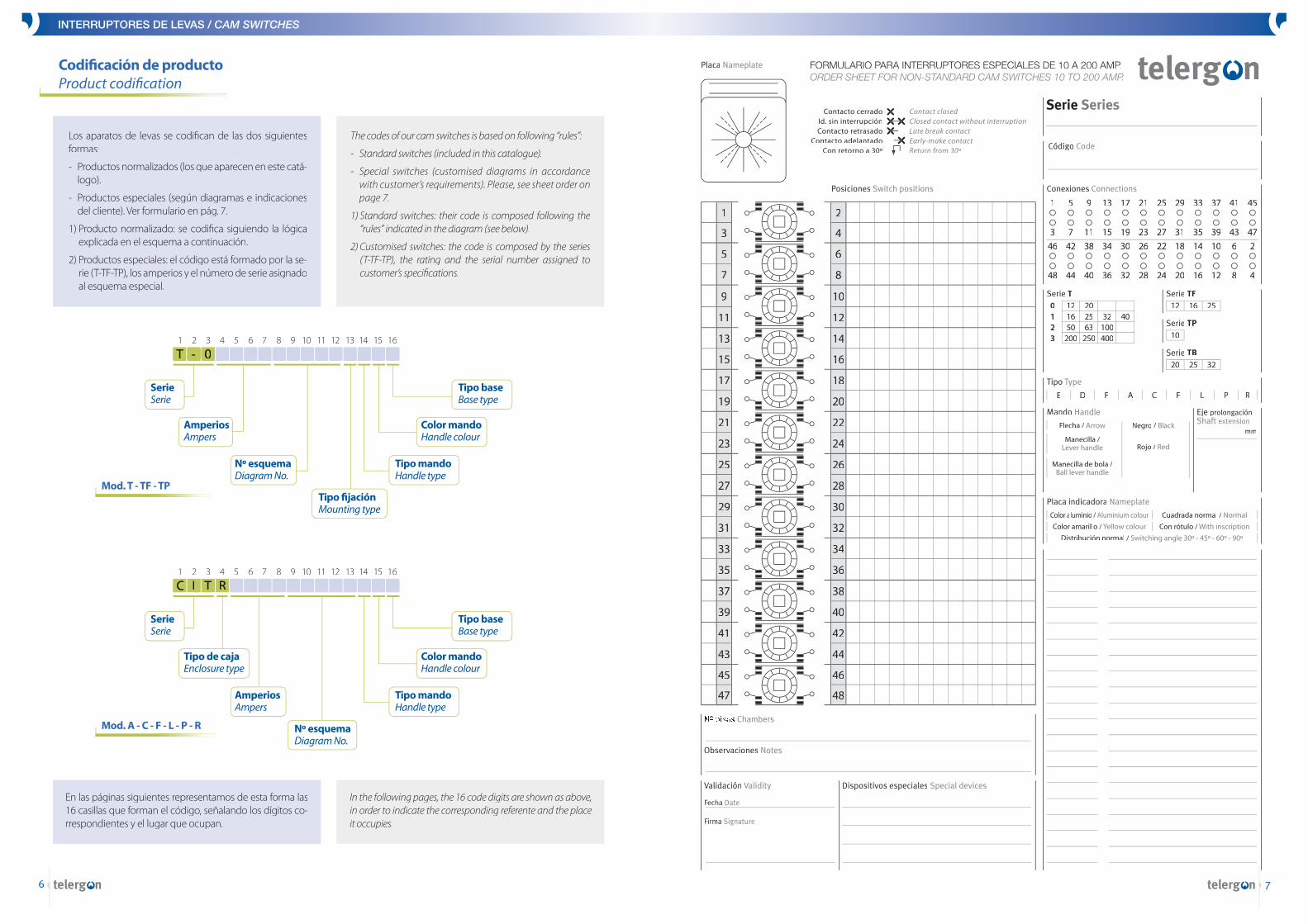
Placa Nameplate
Código CodeLos aparatos de levas se codifi can de las dos siguientes formas:
- Productos normalizados (los que aparecen en este catá-logo).
- Productos especiales (según diagramas e indicaciones del cliente). Ver formulario en pág. 7.
1) Producto normalizado: se codifi ca siguiendo la lógica explicada en el esquema a continuación.
2) Productos especiales: el código está formado por la se-rie (T-TF-TP), los amperios y el número de serie asignado al esquema especial.
The codes of our cam switches is based on following “rules”:
- Standard switches (included in this catalogue).
- Special switches (customised diagrams in accordance with customer’s requirements). Please, see sheet order on page 7.
1) Standard switches: their code is composed following the “rules” indicated in the diagram (see below).
2) Customised switches: the code is composed by the series (T-TF-TP), the rating and the serial number assigned to customer’s specifi cations.
En las páginas siguientes representamos de esta forma las 16 casillas que forman el código, señalando los dígitos co-rrespondientes y el lugar que ocupan.
In the following pages, the 16 code digits are shown as above, in order to indicate the corresponding referente and the place it occupies.
SerieSerie
T - 0T - 0T - 0T - 0T - 0 1 2 3 4 5 6 7 8 9 10 11 12 13 14 15 16
Nº esquemaDiagram No.
Tipo fi jaciónMounting type
AmperiosAmpers
Tipo mandoHandle type
Tipo baseBase type
Color mandoHandle colour
C I T R 1 2 3 4 5 6 7 8 9 10 11 12 13 14 15 16
AmperiosAmpers
Nº esquemaDiagram No.
Tipo mandoHandle type
Tipo baseBase type
Color mandoHandle colour
SerieSerie
Tipo de cajaEnclosure type
Codifi cación de productoProduct codifi cation
Mod. T - TF - TP
Mod. A - C - F - L - P - R
E D F A C L P RF
Serie T Serie TF12 16 250 12 20
1 16 25 32 402 50 63 1003 200 250 400
Serie TP10
Serie TB20 25 32
INTERRUPTORES DE LEVAS / CAM SWITCHES
8
INTERRUPTORES DE LEVAS / CAM SWITCHES
9
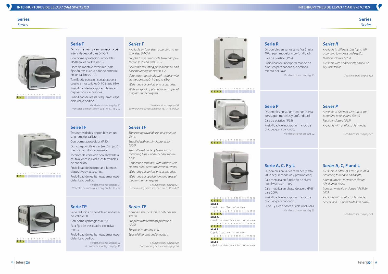
Disponibles en cuatro tamaños según intensidades, calibres 0-1-2-3.
Con bornes protegidos amovibles (IP20) en los calibres 0-1-2.
Placa de montaje reversible (para fi jación tras cuadro o fondo armario) en los calibres 0-1-2.
Tornillos de conexión con abrazadera cautiva en los calibres 0- 1-2 (hasta 63A).
Posibilidad de incorporar diferentes dispositivos y accesorios.
Posibilidad de realizar esquemas espe-ciales bajo pedido.
Ver dimensiones en pág. 20Ver cotas de montaje en pág. 16, 17, 18 y 22
Serie TAvailable in four sizes according to ra-ting: sizes 0-1-2-3.
Supplied with removable terminals pro-tection (IP20) on sizes 0-1-2 .
Reversible mounting plate (for panel and base mounting) on sizes 0-1-2.
Connection terminals with captive wire clamps on sizes 0- 1-2 (up to 63A).
Wide range of devices and accessories.
Wide range of applications and special diagrams under request.
See dimensions on page 20See mounting dimensions on p. 16, 17, 18 and 22
Series T
Tres intensidades disponibles en un solo tamaño, calibre 1.
Con bornes protegidos (IP20).
Dos cuerpos diferentes (según fi jación tras cuadro o fondo armario).
Tornillos de conexión con abrazadera cautiva. Acceso axial a los terminales de conexión.
Posibilidad de incorporar diferentes dispositivos y accesorios.
Posibilidad de realizar esquemas espe-ciales bajo pedido.
Ver dimensiones en pág. 21Ver cotas de montaje en pág. 16, 17, 19 y 22
Serie TFThree ratings available in only one size: size 1.
Supplied with terminals protection (IP20).
Two diff erent bodies (depending on mounting type – panel or base moun-ting).
Connection terminals with captive wire clamps. Axial access to terminal screws.
Wide range of devices and accessories.
Wide range of applications and special diagrams under request.
See dimensions on page 21 See mounting dimensions on p. 16, 17, 19 and 22
Series TF
Serie reducida disponible en un tama-ño, calibre 00.
Con bornes protegidos (IP20).
Para fi jación tras cuadro exclusiva-mente.
Posibilidad de realizar esquemas espe-ciales bajo pedido.
Ver dimensiones en pág. 20 Ver cotas de montaje en pág. 16
Serie TPCompact size available in only one size: size 00.
Supplied with terminals protection (IP20).
For panel mounting only.
Special diagrams under request.
See dimensions on page 20 See mounting dimensions on page 16
Series TP
Disponibles en varios tamaños (hasta 40A según modelos y profundidad).
Caja de plástico (IP65).
Posibilidad de incorporar mando de bloqueo para candado, o acciona-miento por llave.
Ver dimensiones en pág. 22
Serie RAvailable in diff erent sizes (up to 40A according to models and depth).
Plastic enclosure (IP65).
Available with padlockable handle or key lock device.
See dimensions on page 22
Series R
Disponibles en varios tamaños (hasta 40A según modelos y profundidad).
Caja de plástico (IP65).
Posibilidad de incorporar mando de bloqueo para candado.
Ver dimensiones en pág. 22
Serie PAvailable in diff erent sizes (up to 40A according to series and depth).
Plastic enclosure (IP65).
Available with padlockable handle.
See dimensions on page 22
Series P
Disponibles en varios tamaños (hasta 200A según modelos y profundidad).
Caja metálica en fundición de alumi-nio (IP65) hasta 100A.
Caja metálica en chapa de acero (IP65) para 200A.
Posibilidad de incorporar mando de bloqueo para candado.
Serie F y L con bases fusibles incluidas.Ver dimensiones en pág. 23
Serie A, C, F y LAvailable in diff erent sizes (up to 200A according to models and depth).
Aluminium cast metallic enclosure (IP65) up to 100A .
Iron cast metallic enclosure (IP65) for 200A.
Available with padlockable handle.
Series F and L supplied with fuse holders.
See dimensions on page 23
Series A, C, F and L
SeriesSeries
SeriesSeries
T F -
T -
T P -
1 2 3 4 5 6 7 8 9 10 11 12 13 14 15 16
1 2 3 4 5 6 7 8 9 10 11 12 13 14 15 16
1 2 3 4 5 6 7 8 9 10 11 12 13 14 15 16
C I TI TI TI T CMod. CCaja de chapa / Iron cast enclosure
1 2 3 4 5 6 7 8 9 10 11 12 13 14 15 16
C I TI TI TI T AAMod. ACaja de aluminio / Aluminium cast enclosure
1 2 3 4 5 6 7 8 9 10 11 12 13 14 15 16
C I TI TI TI T FMod. FCaja de chapa / Iron cast enclosure
1 2 3 4 5 6 7 8 9 10 11 12 13 14 15 16
C I TI TI TI T LMod. LCaja de aluminio / Aluminium cast enclosure
1 2 3 4 5 6 7 8 9 10 11 12 13 14 15 16
C I TI TI TI T P 1 2 3 4 5 6 7 8 9 10 11 12 13 14 15 16
C I TI TI TI T R 1 2 3 4 5 6 7 8 9 10 11 12 13 14 15 16

INTERRUPTORES DE LEVAS / CAM SWITCHES
10
INTERRUPTORES DE LEVAS / CAM SWITCHES
11
AccesoriosAccessories
AccesoriosAccessories
Disponibles en todos los calibres: 0, 1, 2 y 3.
• D100 con lámpara de neón.
• D101 con lámpara de neón y placa para inscripciones.
Ver dimensiones en pág. 24
Señalización mediante lámpara de neón(color blanco)
D100-D101
4
D100
Available for all sizes: 0, 1, 2 and 3.
• D100 with neon light.
• D101 with neon light and small plate for front inscriptions.
See dimensions on page 24
Signalling device with white neon light
D100-D101
Disponibles en todos los calibres: 0, 1, 2 y 3.
Para esquemas eléctricos que requie-ran la maniobra simultánea, con un sólo mando, de hasta 72 contactos (hasta 3 columnas de un máximo de 12 pisos cada una, con dos contactos por piso).
• D200 accionamiento de 2 columnas.
• D201 accionamiento de 3 columnas.Ver dimensiones en pág. 24
Accionamientos tandem entre dos o tres aparatos
D200-D201
Available for all sizes: 0, 1, 2 and 3.
Suitable for electrical diagrams requir-ing simultaneous manoevre, with only one handle, up to 72 contacts (up to 3 columns with max. 12 chambers each, with two contacts per chamber).
• D200 2 columns operation.
• D201 3 columns operation.
See dimensions on page 24
Tandem drive operation with two or three colums
D200-D201
D
D200
ED201
Disponible en todos los calibres: 0, 1, 2 y 3.
Permite aumentar el número máximo de posiciones por mando (12) hasta 32 mediante el uso de 2 ó 3 mandos de forma que la maniobra de uno de ellos sólo es posible mecánicamente si el resto están en la posición inicial (“0” en la fi gura).
• D300 accionamiento de 2 columnas.
• D301 accionamiento de 3 columnas.Ver dimensiones en pág. 24
Accionamientos de bloqueo entre dos o tres aparatos
D300-D301
Available for all sizes: 0, 1, 2 and 3.
This device provides an increase of the maximum number of positions per handle (12) up to 32 by means of the use of 2 or 3 handles. It is possible to operate mechanically one handle, only when the other(s) is(are) in initial position (0 in the picture).
• D300 2 columns operation.
• D301 3 columns operation.
See dimensions on page 24
Blocking operation with two or three switches
D300-D301
F
D300
GD301
Pulsando el mando para accionar, se abre o se cierra un contacto auxiliar.
Disponible en los calibres 0 y 1 de Mod T.
Pulsar para girarD400
Pushing the handle to operate, an auxi-liary contact makes or breaks.
Available for sizes 0 and 1 on Mod T.
Push to turnD400
Permite el giro del mando en un solo sentido.
Disponible en calibres 0 y 1 de Mod T.
Giro unidireccionalD405
This device allows to rotate the handle in only one way.
Available for sizes 0 and 1 on Mod T.
One way rotationD405
Con bloqueo de puerta en posición conectado.
Disponible en todos los calibres.
Ver cotas de montaje en pág. 18-19
Embrague con enclavamiento de puerta
D501
With door interlocking in “ON” position.
Available for all sizes.
See mounting dimensions on pages 18-19
Clutch device with door intelock
D501
La posición del tornillo, situándolo a izquierda o derecha, impedirá el giro en sentido contrario. Este dispositivo incluye siempre la placa de anclaje correspondiente al calibre 1.
Disponible en calibres 0 y 1 de Mod. T y TF.
Bloqueo bitensiónD420
Screw on right or left position to stop the handle turning on the other way. This device includes always the anchorage plate corresponding to size 1.
Available for sizes 0 and 1 on Mod T and TF.
Locking voltage deviceD420
Acoplamiento coaxialD600
Simultaneous operation with only one handle of two or more switches with diff erent rating coupled together.
Available for all sizes on Mod. T.
Coaxial couplingD600
Permite la maniobra con un solo mando de interruptores de distintos tamaños.
Disponible en todos los calibres de Mod. T.
1 2 3 4 5 6 7 8 9 10 11 12 13 14 15 16
5D101
1 2 3 4 5 6 7 8 9 10 11 12 13 14 15 16
1 2 3 4 5 6 7 8 9 10 11 12 13 14 15 16
1 2 3 4 5 6 7 8 9 10 11 12 13 14 15 16
1 2 3 4 5 6 7 8 9 10 11 12 13 14 15 16
1 2 3 4 5 6 7 8 9 10 11 12 13 14 15 16
I 1 2 3 4 5 6 7 8 9 10 11 12 13 14 15 16
H 1 2 3 4 5 6 7 8 9 10 11 12 13 14 15 16
3 1 2 3 4 5 6 7 8 9 10 11 12 13 14 15 16
F 1 2 3 4 5 6 7 8 9 10 11 12 13 14 15 16
B 1 2 3 4 5 6 7 8 9 10 11 12 13 14 15 16
12
INTERRUPTORES DE LEVAS / CAM SWITCHES
12
INTERRUPTORES DE LEVAS / CAM SWITCHES
13
AccesoriosAccessories
AccesoriosAccessories
La llave puede ser extraida según demanda a 60º, 90º ó 180º.
Limitación de montaje: 4 contactos acciona-dos simultaneamente.
Disponible en los calibres 0 y 1 de Mod. T y TF.
Accionamiento por llaveD701
The key can be withdrawn at 60º, 90º or 180º, The key can be withdrawn at 60º, 90º or 180º, The key can be withdrawn at 60º, 90º or 180ºunder request.
Mounting limitation: 4 contacts operated simultaneously.
Available for sizes 0 and 1 on Mod. T and TF.
Key handle deviceD701
Ambos dispositivos admiten la adaptación de 1 ó 2 contactos auxiliares conmutados (1a+1c), que son accionados mientras gira-mos la llave para establecer el bloqueo.
D703 con placa para inscripciones.
Disponible en todos los calibres de Mod. T y TF.Ver dimensiones en pág. 24
Cerradura de bloqueoD702-703
Both devices can be supplied with one or two auxiliary contacts 1NO+1NC, which are oper-ated by turning the key to lock.
D703 with inscription plate.
Available for all sizes on Mod. T y TF.
See dimensions on page 24
Key lock deviceD702-703
Disponible con mando rojo sobre fondo amari-llo (R) o con mando negro sobre fondo gris (N).
Especifi car versión (R ó N) en el caso de interruptores 0-I. En el resto de aplicaciones se suministrará la versión N.
Los candados no se suministran.
El mando bloqueable por candado puede aplicarse a los montajes en caja tipos A, C, F, L, P y R.
De acuerdo con la directiva de máquinas y la normativa europea vigente, los colores rojo sobre fondo amarillo (versión R) están reservados exclusivamente para su uso en interruptores 0-I que cumplan la función de desconexión de la alimentanción y la de parada de emergencia.
D705 con placa para inscripciones.
Disponible en todos los calibres de Mod. T y TF.Ver dimensiones en pág. 26
Mando bloqueable por candadoD704-705
Available with red on yellow (R) or black on grey handle (N).
Specify version (R or N) in case of ON-OFF switches. For other applications N version will be supplied.
Padlocks are not included.
The padlockable handle can be used in the enclosed versions A, C, F, L, P and R.
According to the machinery directive and the european standard, the colour red on yellow (R) are intended to be used only in ON-OFF safety switches.
D705 with inscription plate.
Available for all sizes on Mod. T and TF.
See dimensions on page 26
Padlockable handleD704-705
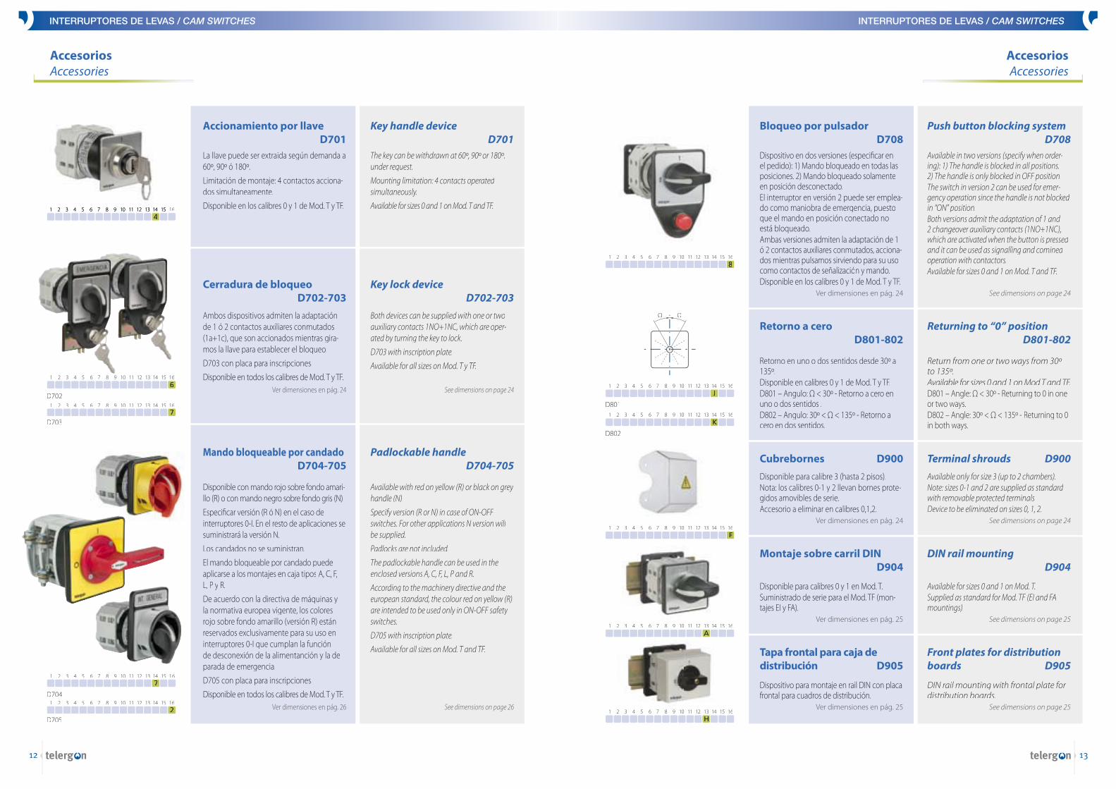
Dispositivo en dos versiones (especifi car en el pedido): 1) Mando bloqueado en todas las posiciones. 2) Mando bloqueado solamente en posición desconectado.El interruptor en versión 2 puede ser emplea-do como maniobra de emergencia, puesto que el mando en posición conectado no está bloqueado.Ambas versiones admiten la adaptación de 1 ó 2 contactos auxiliares conmutados, acciona-dos mientras pulsamos sirviendo para su uso como contactos de señalización y mando.Disponible en los calibres 0 y 1 de Mod. T y TF.
Ver dimensiones en pág. 24
Bloqueo por pulsadorD708
Available in two versions (specify when order-ing): 1) The handle is blocked in all positions.2) The handle is only blocked in OFF position.The switch in version 2 can be used for emer-gency operation since the handle is not blocked in “ON” position.Both versions admit the adaptation of 1 and 2 changeover auxiliary contacts (1NO+1NC), which are activated when the button is pressed and it can be used as signalling and comined operation with contactors.Available for sizes 0 and 1 on Mod. T and TF.
See dimensions on page 24
Push button blocking systemD708
Retorno en uno o dos sentidos desde 30º a 135º.Disponible en calibres 0 y 1 de Mod. T y TF.D801 – Angulo: Ω < 30º - Retorno a cero en uno o dos sentidos .D802 – Angulo: 30º < Ω < 135º - Retorno a cero en dos sentidos.
Retorno a ceroD801-802
Return from one or two ways from 30º to 135º.Available for sizes 0 and 1 on Mod T and TF.D801 – Angle: Ω < 30º - Returning to 0 in one or two ways.D802 – Angle: 30º < Ω < 135º - Returning to 0 in both ways.
Returning to “0” positionD801-802
Disponible para calibres 0 y 1 en Mod. T.Suministrado de serie para el Mod. TF (mon-tajes EI y FA).
Ver dimensiones en pág. 25
Montaje sobre carril DIN D904
Available for sizes 0 and 1 on Mod. T.Supplied as standard for Mod. TF (EI and FA mountings).
See dimensions on page 25
DIN rail mountingD904
Disponible para calibre 3 (hasta 2 pisos).Nota: los calibres 0-1 y 2 llevan bornes prote-gidos amovibles de serie.Accesorio a eliminar en calibres 0,1,2.
Ver dimensiones en pág. 24
Cubrebornes D900
Available only for size 3 (up to 2 chambers).Note: sizes 0-1 and 2 are supplied as standard with removable protected terminals.Device to be eliminated on sizes 0, 1, 2.
See dimensions on page 24
Terminal shrouds D900
Tapa frontal para caja de distribución D905
DIN rail mounting with frontal plate for distribution boards.
See dimensions on page 25
Front plates for distribution boards D905
Dispositivo para montaje en rail DIN con placa frontal para cuadros de distribución.
Ver dimensiones en pág. 25
7
D704
2D705
1 2 3 4 5 6 7 8 9 10 11 12 13 14 15 16
1 2 3 4 5 6 7 8 9 10 11 12 13 14 15 16
7D703
1 2 3 4 5 6 7 8 9 10 11 12 13 14 15 16
6
D702
1 2 3 4 5 6 7 8 9 10 11 12 13 14 15 16
4 1 2 3 4 5 6 7 8 9 10 11 12 13 14 15 16 1 2 3 4 5 6 7 8 9 10 11 12 13 14 15 16
8 1 2 3 4 5 6 7 8 9 10 11 12 13 14 15 16
J
D801
1 2 3 4 5 6 7 8 9 10 11 12 13 14 15 16
K
D802
1 2 3 4 5 6 7 8 9 10 11 12 13 14 15 16
E 1 2 3 4 5 6 7 8 9 10 11 12 13 14 15 16
A 1 2 3 4 5 6 7 8 9 10 11 12 13 14 15 16
H 1 2 3 4 5 6 7 8 9 10 11 12 13 14 15 16
Ω Ω
INTERRUPTORES DE LEVAS / CAM SWITCHES
14
INTERRUPTORES DE LEVAS / CAM SWITCHES
15
AccesoriosAccessories
Accesorios - MandosAccessories - Handles
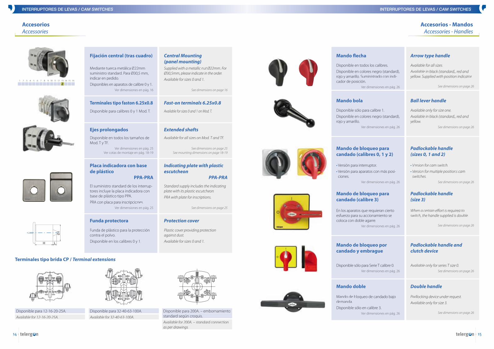
Disponible para calibres 0 y 1 Mod. T.
Terminales tipo faston 6.25x0.8
Available for sizes 0 and 1 on Mod. T.
Fast-on terminals 6.25x0.8
Mediante tuerca metálica Ø22mm suministro standard. Para Ø30,5 mm, indicar en pedido.
Disponibles en aparatos de calibre 0 y 1.Ver dimensiones en pág. 16
Fijación central (tras cuadro)
Supplied with a metallic nut Ø22mm. For Ø30,5mm, please indicate in the order.
Available for sizes 0 and 1.
See dimensions on page 16
Central Mounting(panel mounting)
Z 1 2 3 4 5 6 7 8 9 10 11 12 13 14 15 16
Disponible en todos los tamaños de Mod. T y TF.
Ver dimensiones en pág. 25 Ver cotas de montaje en pág. 18-19
Ejes prolongados
Available for all sizes on Mod. T and TF.
See dimensions on page 25 See mounting dimensions on page 18-19
Extended shafts
El suministro standard de los interrup-tores incluye la placa indicadora con base de plástico tipo PPA.
PRA con placa para inscripciones.Ver dimensiones en pág. 25
Placa indicadora con base de plástico PPA-PRA
Standard supply includes the indicating plate with its plastic escutcheon.
PRA with plate for inscriptions.
See dimensions on page 25
Indicating plate with plastic escutcheon PPA-PRA
Disponible para 12-16-20-25A.
Available for 12-16-20-25A.
Terminales tipo brida CP / Terminal extensions
Disponible para 32-40-63-100A.
Available for 32-40-63-100A.
Disponible para 200A. – embornamientostandard según croquis.standard según croquis.
Available for 200A. – standard connectionas per drawings.as per drawings.
Funda de plástico para la protección contra el polvo.
Disponible en los calibres 0 y 1.
Funda protectora
Plastic cover providing protection against dust.
Available for sizes 0 and 1.
Protection cover
Disponible en todos los calibres.
Disponible en colores negro (standard), rojo y amarillo. Suministrado con indi-cador de posición.
Ver dimensiones en pág. 26
Mando fl echa
Available for all sizes.
Available in black (standard), red and yellow. Supplied with position indicator.
See dimensions on page 26
Arrow type handle
Disponible sólo para calibre 1.
Disponible en colores negro (standard), rojo y amarillo.
Ver dimensiones en pág. 26
Mando bola
Available only for size one.
Available in black (standard), red and yellow.
See dimensions on page 26
Ball lever handle
• Versión para interruptor. Versión para interruptor. V
• Versión para Versión para V aparatos con más posi-ciones.
Ver dimensiones en pág. 26
Mando de bloqueo para candado (calibres 0, 1 y 2)
• Version for cam switcVersion for cam switcV h.
• Version for multiple positions cam switches.
See dimensions on page 26
Padlockable handle(sizes 0, 1 and 2)
En los aparatos que requieran cierto esfuerzo para su accionamiento se coloca con doble agarre.
Ver dimensiones en pág. 26
Mando de bloqueo para candado (calibre 3)
When a certain eff ort is required to switch, the handle supplied is double.
See dimensions on page 26
Padlockable handle(size 3)
Disponible sólo para Serie T calibre 0.Ver dimensiones en pág. 26
Mando de bloqueo por candado y embrague
Avaliable only for series T size 0.See dimensions on page 26
Padlockable handle and clutch device
Mando de bloqueo de candado bajo demanda.
Disponible sólo en calibre 3.Ver dimensiones en pág. 26
Mando doble
Padlocking device under request.
Available only for size 3.
See dimensions on page 26
Double handle
Ø1
H L
16
INTERRUPTORES DE LEVAS / CAM SWITCHES
17
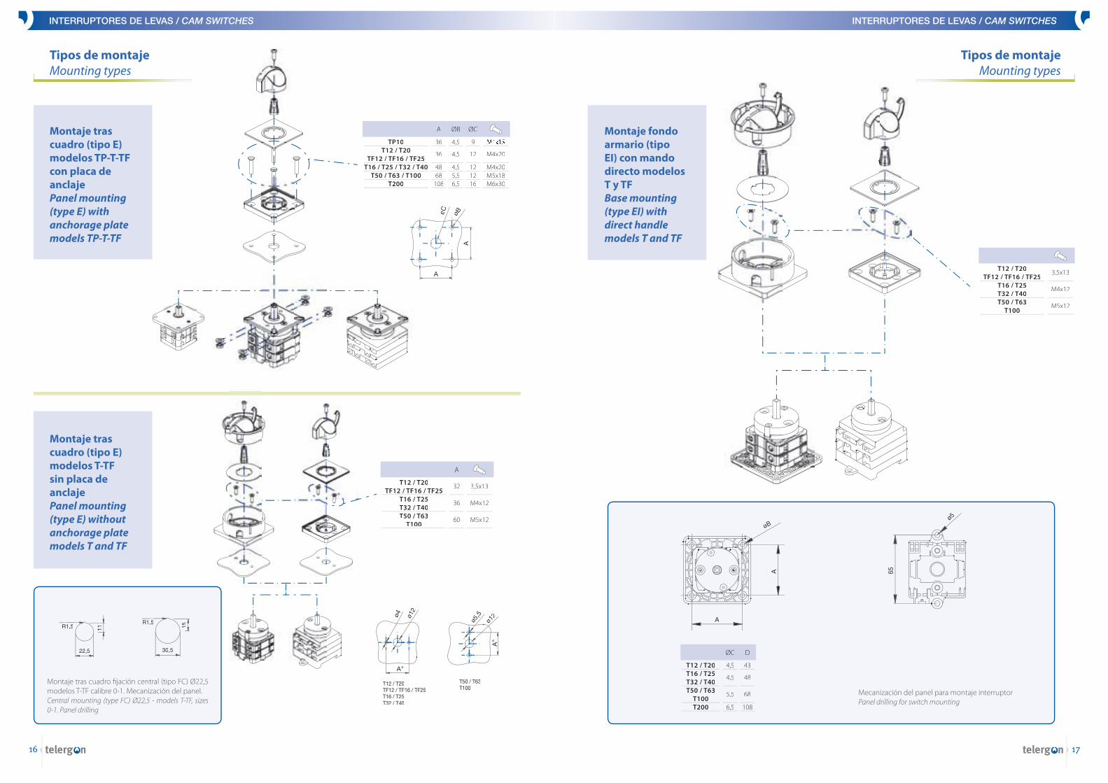
Montaje fondo armario (tipo EI) con mando directo modelosT y TFBase mounting (type EI) with direct handle models T and TF
Tipos de montajeMounting types
Montaje tras cuadro (tipo E) modelos TP-T-TFcon placa de anclajePanel mounting (type E) with anchorage plate models TP-T-TF
Montaje tras cuadro (tipo E) modelos T-TFsin placa de anclajePanel mounting (type E) without anchorage plate models T and TF
Montaje tras cuadro fi jación central (tipo FC) Ø22,5 modelos T-TF calibre 0-1. Mecanización del panel.Central mounting (type FC) Ø22,5 - models T-TF, sizes 0-1. Panel drilling
Tipos de montajeMounting types
Mecanización del panel para montaje interruptorPanel drilling for switch mounting
INTERRUPTORES DE LEVAS / CAM SWITCHES
M4x15
M4x20
M4x20M5x18M6x30
TP10T12 / T20
TF12 / TF16 / TF25T16 / T25 / T32 / T40
T50 / T63 / T100T200
ØC
9
12
121216
4,5
4,5
4,55,56,5
36
36
4868
108
ØBA
3,5x13
M4x12
M5x12
T12 / T20TF12 / TF16 / TF25
T16 / T25T32 / T40T50 / T63
T100
32
36
60
A
3,5x13
M4x12
M5x12
T12 / T20TF12 / TF16 / TF25
T16 / T25T32 / T40T50 / T63
T100
T12 / T20T16 / T25T32 / T40T50 / T63
T100T200
43
48
68
108
4,5
4,5
5,5
6,5
DØC
øB
A
A
øC
ø4 ø12
A*
T12 / T20TF12 / TF16 / TF25T16 / T25T32 / T40
T50 / T63T100
ø5,5
ø12
A*
30,5
15
R1,5
22,5
11R1,5
øB
A
A
65
ø5

18
INTERRUPTORES DE LEVAS / CAM SWITCHES
19
Montaje fondo armario (tipo FA) serie TBase mounting (type FA) series T
1
121283
135,1297,1138,5300,5152,5314,5161323
min.máx.min.máx.min.máx.min.máx.min.máx.
2 3 + ØAL = (mm)
T12 / T20
T16 / T25
T32 / T40
T50 / T63
T100
132,5294,5149,3311,3156318
172,5334,5188350
144306
163,5325,5173,5335,5192,5354,5215377
+11,5
+14,2
+17,5
+20
+27
9
9
9
12
12
1
8397,1
100,5114,5123165
2 3 + ØAL = (mm)
T12 / T20T16 / T25T32 / T40T50 / T63
T100T200
94,5111,3118
134,5150205
106125,5135,5154,5177245
+11,5+14,2+17,5+20+27+40
999
121216
45,547,547,5525270
B
4,5
4,5
5,5
6,5
ØC
T12 / T20T16 / T25T32 / T40T50 / T63
T100T200
D
43
48
68
108
Tipos de montajeMounting types
Tipos de montajeMounting types
Longitud / Lenght
Longitud / Lenght
INTERRUPTORES DE LEVAS / CAM SWITCHES
L = (mm)
95,5TF12/TF16/TF25 105,5 115,5 +10
Longitud / Lenght
1 2 3 + 1
133,5295,5
min.máx.
2 3 +L = (mm)
TF12 / TF16 / TF25 143,5305,5
153,5315,5
+10
Longitud / Lenght
3,5x13
32
ø9
ø4
3,5x19
ø5
65
3max
.45
,5
3max
.
3,5x13
M4x12
M5x12
T12 / T20T16 / T25T32 / T40T50 / T63
T100
3,5x13
3,5x13
M4x25
M4x25
T12 / T20T16 / T25T32 / T40T50 / T63
T100T200
Montaje fondo armario (tipo FA) serie TFBase mounting (type FA) series TF
øA
32
ø4
48
48
ø4,5
øA
4832
48
ø4,5
øA
øAø4
3,5x19
3max
.
1+1 -0
L
3max
.B
L
øC
D
D
L
L
1+1 -0
INTERRUPTORES DE LEVAS / CAM SWITCHES
20
INTERRUPTORES DE LEVAS / CAM SWITCHES
21
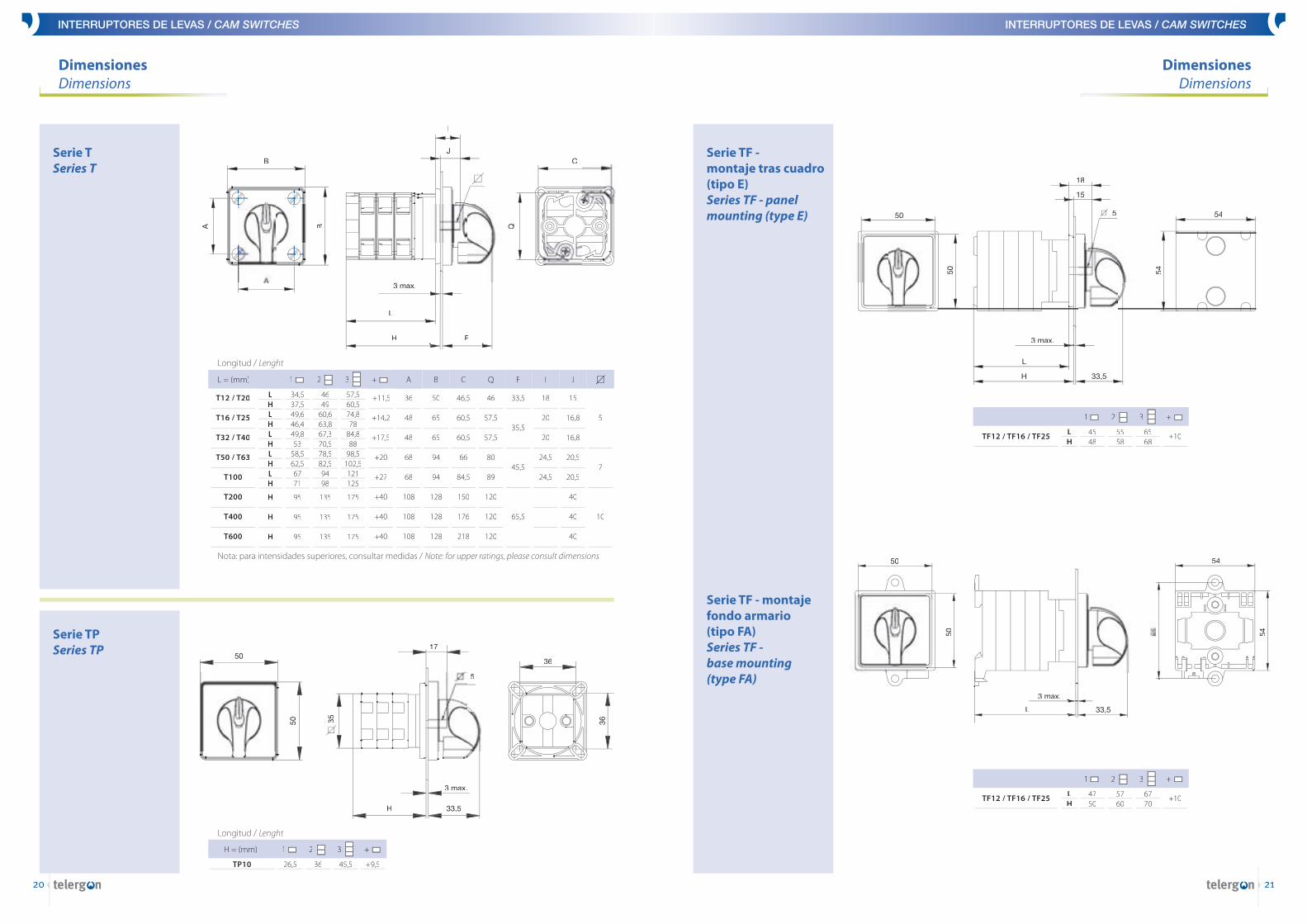
DimensionesDimensions
DimensionesDimensions
Serie TSeries T
Serie TPSeries TP
1
34,537,549,646,449,853
58,562,56771
95
95
95
LHLHLHLHLH
H
H
H
2 3 + AL = (mm)
T12 / T20
T16 / T25
T32 / T40
T50 / T63
T100
T200
T400
T600
4649
60,663,867,370,578,582,59498
135
135
135
57,560,574,878
84,888
98,5102,5121125
175
175
175
+11,5
+14,2
+17,5
+20
+27
+40
+40
+40
36
48
48
68
68
108
108
108
Longitud / Lenght
B
50
65
65
94
94
128
128
128
C
46,5
60,5
60,5
66
84,5
150
176
218
Q
46
57,5
57,5
80
89
120
120
120
F
33,5
35,5
45,5
65,5
I
18
20
20
24,5
24,5
-
-
-
J
15
16,8
16,8
20,5
20,5
40
40
40
5
7
10
Nota: para intensidades superiores, consultar medidas / Note: for upper ratings, please consult dimensions
H = (mm)
26,5TP10 36 45,5 +9,5
Longitud / Lenght
1 2 3 +
Serie TF -montaje tras cuadro (tipo E) Series TF - panel mounting (type E)
Serie TF - montaje fondo armario (tipo FA)Series TF -base mounting(type FA)
4548
TF12 / TF16 / TF25 5558
6568
+10
1 2 3 +
LH
4750
TF12 / TF16 / TF25 5760
6770
+10
1 2 3 +
LH
50
50 35
H 33,5
3 max.
5
17
36
36
B
A
A B
I
J
3 max.
L
H F
Q
C
3 max.
50
50
18
L
H 33,5
15
5 54
54
50
50
L
3 max.
33,5
65 54
54

INTERRUPTORES DE LEVAS / CAM SWITCHES
22
INTERRUPTORES DE LEVAS / CAM SWITCHES
23
DimensionesDimensions
Modelos T y TF en caja de plástico (P)Models T and TF with plastic enclosure (P)
Modelos T y TF en caja de plástico (P)y mando bloqueable por candado D704Models T and TF with plastic enclosure (P) and padlockable handle D704
Modelos T y TF en caja de plástico (R)Models T and TF with plastic enclosure (R)
Modelos T y TF en caja de plástico (R)y mando bloqueable por candado D704Models T and TF with plastic enclosure (R) and padlockable handle D704
nº 1nº 2nº 3nº 4
pisos / chambers (max)
2346
cajabox
T12 / T20
1234
T16 / T25
1-34
T32 / T40 PG
16161616
C
7286
100114
nº 1nº 2nº 3nº 4
pisos / chambers (max)
2346
cajabox
T12 / T20
1234
T16 / T25
1-23
T32 / T40 PG
16161616
C
7286
100114
PG
ABCFG
3
13,516
caja / box
T12T20
T16T25
T16T25
pisos / chambers (max)
T12T20
T16T25
T16T25
313,5162192
1448678
101
2
1621
4
13,516
413,5162192
1448678
101
3
1621
2 3
PG
ABCFG
21
120180
116,5106146
caja / box
T32
pisos / chambers (max)
T40
4
3
29
120180
116,5106146
Modelos T y TF en caja de aluminio (A)Models T and TFwith aluminiumenclosure (A)
DimensionesDimensions
nº 1nº 2nº 3nº 4nº 5nº 6
pisos / chambers(max)
6-9-
12-
cajaencl.
T12 / T20
4-7-
11-
T16 / T25
-3-6-9
T32 / T40 PG
162116161621
A
118118240240118118
B
118118180180240240
C
8585
120120120120
D
404056565656
E
252525252525
F
8484
219219159159
G
104104159159219219
ØH
4,54,56,56,56,56,5
I
313131313131
nº 1nº 2nº 3
pisos / chambers(max)
5--
cajaencl.
T50 / T63
-33
T100 PG
212136
A
240325325
B
180180180
C
120120120
D
565656
E
353535
F
219304304
G
159159159
ØH
6,56,56,5
I
414141
nº 1nº 2
pisos / chambers(max)
9-
cajaencl.
T12 / T20
7-
T16 / T25
-6
T32 / T40 PG
1616/21*
A
180180
B
325325
C
120120
D
5656
E
3535
F
159159
G
304304
ØH
4,54,5
I
3131
*T32
nº 1
pisos / chambers(max)
5
cajaencl.
T50 / T63
-
T100 PG
21
A
180
B
325
C
120
D
56
E
35
F
159
G
304
ØH
6,5
I
41
Serie T en cajade aluminio conbases fusibles (L)Series T with cast aluminium enclosure with fuse holders (L)
T100T200T100T200
pisos / chambers (max)5525
A
155210200200
B
250300300400
C
300400400500
D
150200200250
E
45,565,545,565,5
caja Cencl. Ccaja Fencl. F
nº 1
Serie T en cajade chapa (C) y caja de chapa conbases fusibles (F)Series T with cast iron enclosure ( C) and iron enclosure with fuse holders (F)
PG
C 2929,529,5
151515
927232
92 50
C 399272 29,529,529,529,532 15
92 50
PG
AF36
Ø4,5
B G
C 39PG
21
AF36 PG
C 29
B G
21
BI
G
PG
D
E
C
A
FØH
B
G
C
E
ØH
A
F
D
I
PG
B I
C
A
D
INTERRUPTORES DE LEVAS / CAM SWITCHES
24
INTERRUPTORES DE LEVAS / CAM SWITCHES
25
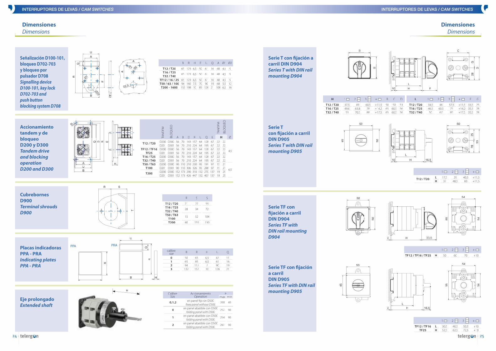
DimensionesDimensions
DimensionesDimensions
Serie T con fi jación a carril DIN D904Series T with DIN rail mounting D904
Serie TF con fi jación a carril DIN D904Series TF with DIN rail mounting D904
Serie Tcon fi jación a carril DIN D905Series T with DIN rail mounting D905
Serie TF con fi jación a carrilDIN D905Series TF with DIN rail mounting D905
17,537
T12 / T20 2948,5
40,560
+11,5+11,5
1 2 3 +
LH
H
37,549,653
T12 / T20T16 / T25T32 / T40
4963,870,5
60,57888
+11,5+14,2+17,5
1 2 3 +
506565
B
5060,560,5
C
535656
D L
34,546,550
T12 / T20T16 / T25T32 / T40
4660,567
57,57585
+11,5+14,2+17,5
1 2 3 +
33,535,535,5
F
252828
G
30,552,5
TF12 / TF16TF25
40,562,5
50,572,5
+10+100
1 2 3 +
LH
50TF12 / TF16 / TF25 60 70 +10
1 2 3 +
H
Señalización D100-101,bloqueo D702-703y bloqueo porpulsador D708Signalling deviceD100-101, key lockD702-703 andpush buttonblocking system D708
Accionamiento tandem y de bloqueoD200 y D300 Tandem drive and blocking operationD200 and D300
Eje prolongado Extended shaft
AccionamientoOperation
en panel fi jo sin D500fi xed panel without D500panel without D500
en panel abatible con D500folding folding panel with D500panel with D500
en panel abatible con D500folding folding panel with D500panel with D500
en panel abatible con D500folding folding panel with D500panel with D500
CalibreSize
0,1,2
0
1
2
200
252
254
261
Hmax min
40
90
90
90
Cubrebornes D900 Terminal shrouds D900
Placas indicadoras PPA - PRA Indicating platesPPA - PRA
D200D201D200D201D200D201D200D201D200D201
T12 / T20
TF12 / TF16TF25
T16 / T25T32 / T40T50 / T63
T100
T200
D300D301D300D301D300D301D300D301D300D301
5656565656569090
152152
707070707070
110110173173
143210143210143210210306290426
157224157224157224230326310447
6464646464649595
132132
128195128195128195191288270407
6767676767679797
137137
22222222222215151919
22222222222221212525
4,5
6,5
TAN
DEM
ABLO
QU
EO
B D R U Q E
TAN
DEM
BLO
QU
EO
ØH
21
28
15
40
R
T12 / T20T16 / T25T32 / T40T50 / T63
T100T200
S
27
34
52
155
S
59
72
104
130
506594
132
B
0123
R
6585
117157
H
6,56,57
10
calibresize U
476190
126
Q
11161921
65
65
6594
132
B
T12 / T20T16 / T25T32 / T40
TF12 / 16 / 25T50 / 63 / 100
T200 - 1600
123
123
123160198
R
6,5
6,5
6,57,510
H
50
50
507085
E
61
61
6190
126
U
16
16
161921
Q
48
48
4868
108
A
4,5
4,5
4,55,56,5
Ø1
9
9
91216
Ø2
HH
UB
Ø
H
ERDQ
RR SS
T
PPA
B
PRA
B
RQ
U
H
R
Q
B
U
A
Ø1
E
Ø2222
H
22,5
Ø2
Ø1
A
E
A
53
45 50
L
H10 16,5
50
2528
53
C
G28
D
10 H
L
F
53
45
LH2 16,5
54
65 54
50
50
2 H
65 54
54

INTERRUPTORES DE LEVAS / CAM SWITCHES
26
INTERRUPTORES DE LEVAS / CAM SWITCHES
27
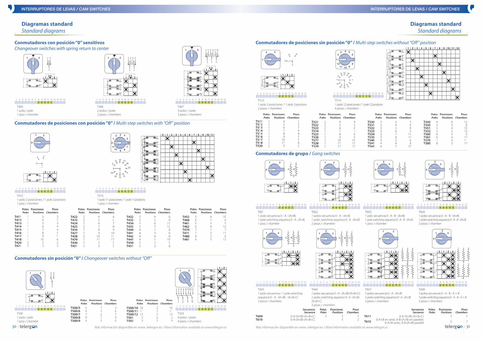
Diagramas standardStandard diagrams
T0101 polo / poles1 piso / break chambers
Interruptores / On-Off switches
T0112 polos / poles1 piso / break chambers
1 2 3 4 5 6 7 8 9 10 11 12 13 14 15 16 0 0 0 1 0 0 0 0 1 0 0 0 0 1 0 0 0 0 1 0 0 0 0 1 0 0 0 0 1 0 0 0 0 1 0 0 0 0 1 0 0 0 0 1 0 0 0 0 1 0 0 0 0 1 0 0 0 0 1 0 0 0 0 1 0 0 0 0 1 0 0 0 0 1 0 0 0 0 1 0 0 0 0 1 0 0 0 0 1 0 0 0 0 1 0 0 0 0 1 0 0 0 0 1 0 0 0 0 1 0 0 0 0 1 0 0 0 0 1 0
1 2 3 4 5 6 7 8 9 10 11 12 13 14 15 16 0 0 0 1 1 0 0 0 1 1 0 0 0 1 1 0 0 0 1 1 0 0 0 1 1 0 0 0 1 1 0 0 0 1 1 0 0 0 1 1 0 0 0 1 1 0 0 0 1 1 0 0 0 1 1 0 0 0 1 1 0 0 0 1 1 0 0 0 1 1 0 0 0 1 1 0 0 0 1 1 0 0 0 1 1 0 0 0 1 1 0 0 0 1 1 0 0 0 1 1 0 0 0 1 1 0 0 0 1 1 0 0 0 1 1 0 0 0 1 1
1 2 3 4 5 6 7 8 9 10 11 12 13 14 15 16 0 0 0 1 2 0 0 0 1 2 0 0 0 1 2 0 0 0 1 2 0 0 0 1 2 0 0 0 1 2 0 0 0 1 2 0 0 0 1 2 0 0 0 1 2 0 0 0 1 2 0 0 0 1 2 0 0 0 1 2 0 0 0 1 2 0 0 0 1 2 0 0 0 1 2 0 0 0 1 2 0 0 0 1 2 0 0 0 1 2 0 0 0 1 2 0 0 0 1 2 0 0 0 1 2 0 0 0 1 2 0 0 0 1 2 0 0 0 1 2
1 2 3 4 5 6 7 8 9 10 11 12 13 14 15 16 0 0 0 1 3 0 0 0 1 3 0 0 0 1 3 0 0 0 1 3 0 0 0 1 3 0 0 0 1 3 0 0 0 1 3 0 0 0 1 3 0 0 0 1 3 0 0 0 1 3 0 0 0 1 3 0 0 0 1 3 0 0 0 1 3 0 0 0 1 3 0 0 0 1 3 0 0 0 1 3 0 0 0 1 3 0 0 0 1 3 0 0 0 1 3 0 0 0 1 3 0 0 0 1 3 0 0 0 1 3 0 0 0 1 3 0 0 0 1 3
T0123 polos / poles2 pisos / break chambers
T0134 polos / poles2 pisos / break chambers
Interruptores con contactos de precierreOn-Off switches with contacts leading when making
T0203 polos 1 polo precerrado3 poles 1 pole preclosed2 pisos / break chambers
T0214 polos 1 polo precerrado4 poles 1 pole preclosed2 pisos / break chambers
1 2 3 4 5 6 7 8 9 10 11 12 13 14 15 16 0 0 0 2 0 0 0 0 2 0 0 0 0 2 0 0 0 0 2 0 0 0 0 2 0 0 0 0 2 0 0 0 0 2 0 0 0 0 2 0 0 0 0 2 0 0 0 0 2 0 0 0 0 2 0 0 0 0 2 0 0 0 0 2 0 0 0 0 2 0 0 0 0 2 0 0 0 0 2 0 0 0 0 2 0 0 0 0 2 0 0 0 0 2 0 0 0 0 2 0 0 0 0 2 0 0 0 0 2 0 0 0 0 2 0 0 0 0 2 0
1 2 3 4 5 6 7 8 9 10 11 12 13 14 15 16 0 0 0 2 1 0 0 0 2 1 0 0 0 2 1 0 0 0 2 1 0 0 0 2 1 0 0 0 2 1 0 0 0 2 1 0 0 0 2 1 0 0 0 2 1 0 0 0 2 1 0 0 0 2 1 0 0 0 2 1 0 0 0 2 1 0 0 0 2 1 0 0 0 2 1 0 0 0 2 1 0 0 0 2 1 0 0 0 2 1 0 0 0 2 1 0 0 0 2 1 0 0 0 2 1 0 0 0 2 1 0 0 0 2 1 0 0 0 2 1
1 2 3 4 5 6 7 8 9 10 11 12 13 14 15 16 0 0 0 2 2 0 0 0 2 2 0 0 0 2 2 0 0 0 2 2 0 0 0 2 2 0 0 0 2 2 0 0 0 2 2 0 0 0 2 2 0 0 0 2 2 0 0 0 2 2 0 0 0 2 2 0 0 0 2 2 0 0 0 2 2 0 0 0 2 2 0 0 0 2 2 0 0 0 2 2 0 0 0 2 2 0 0 0 2 2 0 0 0 2 2 0 0 0 2 2 0 0 0 2 2 0 0 0 2 2 0 0 0 2 2 0 0 0 2 2
T0224 polos 3 polo precerrado4 poles 3 poles preclosed2 pisos / break chambers
Inversores sensitivosReversing switches with spring return
T1012 polos / poles2 pisos / break chambers
T1023 polos / poles3 pisos / break chambers
1 2 3 4 5 6 7 8 9 10 11 12 13 14 15 16 0 0 1 0 1 0 0 1 0 1 0 0 1 0 1 0 0 1 0 1 0 0 1 0 1 0 0 1 0 1 0 0 1 0 1 0 0 1 0 1 0 0 1 0 1 0 0 1 0 1 0 0 1 0 1 0 0 1 0 1 0 0 1 0 1 0 0 1 0 1 0 0 1 0 1 0 0 1 0 1 0 0 1 0 1 0 0 1 0 1 0 0 1 0 1 0 0 1 0 1 0 0 1 0 1 0 0 1 0 1 0 0 1 0 1 0 0 1 0 1
1 2 3 4 5 6 7 8 9 10 11 12 13 14 15 16 0 0 1 0 2 0 0 1 0 2 0 0 1 0 2 0 0 1 0 2 0 0 1 0 2 0 0 1 0 2 0 0 1 0 2 0 0 1 0 2 0 0 1 0 2 0 0 1 0 2 0 0 1 0 2 0 0 1 0 2 0 0 1 0 2 0 0 1 0 2 0 0 1 0 2 0 0 1 0 2 0 0 1 0 2 0 0 1 0 2 0 0 1 0 2 0 0 1 0 2 0 0 1 0 2 0 0 1 0 2 0 0 1 0 2 0 0 1 0 2
1 2 3 4 5 6 7 8 9 10 11 12 13 14 15 16 0 0 1 1 1 0 0 1 1 1 0 0 1 1 1 0 0 1 1 1 0 0 1 1 1 0 0 1 1 1 0 0 1 1 1 0 0 1 1 1 0 0 1 1 1 0 0 1 1 1 0 0 1 1 1 0 0 1 1 1 0 0 1 1 1 0 0 1 1 1 0 0 1 1 1 0 0 1 1 1 0 0 1 1 1 0 0 1 1 1 0 0 1 1 1 0 0 1 1 1 0 0 1 1 1 0 0 1 1 1 0 0 1 1 1 0 0 1 1 1
T1112 polos / poles2 pisos / break chambers
1 2 3 4 5 6 7 8 9 10 11 12 13 14 15 16 0 0 1 1 2 0 0 1 1 2 0 0 1 1 2 0 0 1 1 2 0 0 1 1 2 0 0 1 1 2 0 0 1 1 2 0 0 1 1 2 0 0 1 1 2 0 0 1 1 2 0 0 1 1 2 0 0 1 1 2 0 0 1 1 2 0 0 1 1 2 0 0 1 1 2 0 0 1 1 2 0 0 1 1 2 0 0 1 1 2 0 0 1 1 2 0 0 1 1 2 0 0 1 1 2 0 0 1 1 2 0 0 1 1 2 0 0 1 1 2
T1123 polos / poles3 pisos / break chambers
T010/5 5 polos / polesT010/6 6 polos / polesT010/7 7 polos / polesT010/8 8 polos / polesT010/9 9 polos / poles
T010/10 10 polos / polesT010/11 11 polos / polesT010/12 12 polos / polesT010/13 13 polos / polesT010/14 14 polos / poles
T010/15 15 polos / polesT010/16 16 polos / polesT010/17 17 polos / polesT010/18 18 polos / polesT010/19 19 polos / poles
T010/20 20 polos / polesT010/21 21 polos / polesT010/22 22 polos / polesT010/23 23 polos / polesT010/24 24 polos / poles
DimensionesDimensions
Mando fl echa (calibres 0,1, 2 y 3)Arrow type handle(sizes 0, 1, 2 and 3)
Mando bola(calibres 1, 2 y 3)Ball lever handle(sizes 1, 2 and 3)
Mando de bloqueo para candado (calibres 1 y 2)Padlockable handle(sizes 1 and 2)
Mando de bloqueo para candado (calibre 3)Padlockable handle(size 3)
Mando de bloqueo por candado y embrague (calibre 0)Padlockable handle and clutch device (size 0)
Mando doble serie T (calibre 3)Double handleseries T (size 3)
MANDO DOBLEDOUBLE HANDLE
MANDO SIMPLESINGLE HANDLENGLE HANDLENGLE
37,550
66,5100
T12 / T20T32 / T40
T50 / T100T200
30,528
36,554
13,518
22,538
24324462
B H S T Ø
27364576
89106,5151,5
T16 / T40T50 / T100
T200
B
4848,581
H
2426,541,5
S
6580
110
T
32,52652
M
374672
Ø1
18-
32
Ø2
61,589,5
T16 / T40T50 / T100
38,545
3554
3044
B H S T
T1133 polos con contacto3 poles for use with reserving contactors4 pisos / chambers/ chambers/
InversoresReversing switches
1 2 3 4 5 6 7 8 9 10 11 12 13 14 15 16 0 0 1 1 3 0 0 1 1 3 0 0 1 1 3 0 0 1 1 3 0 0 1 1 3 0 0 1 1 3 0 0 1 1 3 0 0 1 1 3 0 0 1 1 3 0 0 1 1 3 0 0 1 1 3 0 0 1 1 3 0 0 1 1 3 0 0 1 1 3 0 0 1 1 3 0 0 1 1 3 0 0 1 1 3 0 0 1 1 3 0 0 1 1 3 0 0 1 1 3 0 0 1 1 3 0 0 1 1 3 0 0 1 1 3 0 0 1 1 3
Más información disponible en www. telergon.es / More information available on www.telergon.es
B
H
T
Ø
H
TS
M
Ø1
Ø2
B
B
H
TS
Ø58
Ø58
123 123
60
Ø58
Ø58
105 29
60
50 33,5
Ø58
123123
60

INTERRUPTORES DE LEVAS / CAM SWITCHES
28
INTERRUPTORES DE LEVAS / CAM SWITCHES
29
Manipuladores sensitivos / Control switches with spring return
T2011 polo normalmente cerradoStart switch 1 poleStart switch 1 poleStart1 piso / chamber
1 2 3 4 5 6 7 8 9 10 11 12 13 14 15 16 0 0 2 0 1 0 0 2 0 1 0 0 2 0 1 0 0 2 0 1 0 0 2 0 1 0 0 2 0 1 0 0 2 0 1 0 0 2 0 1 0 0 2 0 1 0 0 2 0 1 0 0 2 0 1 0 0 2 0 1 0 0 2 0 1 0 0 2 0 1 0 0 2 0 1 0 0 2 0 1 0 0 2 0 1 0 0 2 0 1 0 0 2 0 1 0 0 2 0 1 0 0 2 0 1 0 0 2 0 1 0 0 2 0 1 0 0 2 0 1
1 2 3 4 5 6 7 8 9 10 11 12 13 14 15 16 0 0 2 0 2 0 0 2 0 2 0 0 2 0 2 0 0 2 0 2 0 0 2 0 2 0 0 2 0 2 0 0 2 0 2 0 0 2 0 2 0 0 2 0 2 0 0 2 0 2 0 0 2 0 2 0 0 2 0 2 0 0 2 0 2 0 0 2 0 2 0 0 2 0 2 0 0 2 0 2 0 0 2 0 2 0 0 2 0 2 0 0 2 0 2 0 0 2 0 2 0 0 2 0 2 0 0 2 0 2 0 0 2 0 2 0 0 2 0 2
1 2 3 4 5 6 7 8 9 10 11 12 13 14 15 16 0 0 2 0 3 0 0 2 0 3 0 0 2 0 3 0 0 2 0 3 0 0 2 0 3 0 0 2 0 3 0 0 2 0 3 0 0 2 0 3 0 0 2 0 3 0 0 2 0 3 0 0 2 0 3 0 0 2 0 3 0 0 2 0 3 0 0 2 0 3 0 0 2 0 3 0 0 2 0 3 0 0 2 0 3 0 0 2 0 3 0 0 2 0 3 0 0 2 0 3 0 0 2 0 3 0 0 2 0 3 0 0 2 0 3 0 0 2 0 3
T2021 polo normalmente abiertoStop switch 1 pole1 piso / chamber
T2032 polos normalmente cerradosStart switch 2 polesStart switch 2 polesStart1 piso / chamber
Manipuladores paro-marcha / Stop-Start switches
T2042 polos normalmente abiertosStop switch 2 poles1 piso / chamber
1 2 3 4 5 6 7 8 9 10 11 12 13 14 15 16 0 0 2 0 4 0 0 2 0 4 0 0 2 0 4 0 0 2 0 4 0 0 2 0 4 0 0 2 0 4 0 0 2 0 4 0 0 2 0 4 0 0 2 0 4 0 0 2 0 4 0 0 2 0 4 0 0 2 0 4 0 0 2 0 4 0 0 2 0 4 0 0 2 0 4 0 0 2 0 4 0 0 2 0 4 0 0 2 0 4 0 0 2 0 4 0 0 2 0 4 0 0 2 0 4 0 0 2 0 4 0 0 2 0 4 0 0 2 0 4
Diagramas standardStandard diagrams
Diagramas standardStandard diagrams
1 2 3 4 5 6 7 8 9 10 11 12 13 14 15 16 0 0 2 0 5 0 0 2 0 5 0 0 2 0 5 0 0 2 0 5 0 0 2 0 5 0 0 2 0 5 0 0 2 0 5 0 0 2 0 5 0 0 2 0 5 0 0 2 0 5 0 0 2 0 5 0 0 2 0 5 0 0 2 0 5 0 0 2 0 5 0 0 2 0 5 0 0 2 0 5 0 0 2 0 5 0 0 2 0 5 0 0 2 0 5 0 0 2 0 5 0 0 2 0 5 0 0 2 0 5 0 0 2 0 5 0 0 2 0 5
T205Para uso con contactor With contactor1 piso / chamber
1 2 3 4 5 6 7 8 9 10 11 12 13 14 15 16 0 0 2 0 6 0 0 2 0 6 0 0 2 0 6 0 0 2 0 6 0 0 2 0 6 0 0 2 0 6 0 0 2 0 6 0 0 2 0 6 0 0 2 0 6 0 0 2 0 6 0 0 2 0 6 0 0 2 0 6 0 0 2 0 6 0 0 2 0 6 0 0 2 0 6 0 0 2 0 6 0 0 2 0 6 0 0 2 0 6 0 0 2 0 6 0 0 2 0 6 0 0 2 0 6 0 0 2 0 6 0 0 2 0 6 0 0 2 0 6
T206Con contactor posición Mar. sensitivaWith contactor and spring return1 piso / chamber
1 2 3 4 5 6 7 8 9 10 11 12 13 14 15 16 0 0 2 0 7 0 0 2 0 7 0 0 2 0 7 0 0 2 0 7 0 0 2 0 7 0 0 2 0 7 0 0 2 0 7 0 0 2 0 7 0 0 2 0 7 0 0 2 0 7 0 0 2 0 7 0 0 2 0 7 0 0 2 0 7 0 0 2 0 7 0 0 2 0 7 0 0 2 0 7 0 0 2 0 7 0 0 2 0 7 0 0 2 0 7 0 0 2 0 7 0 0 2 0 7 0 0 2 0 7 0 0 2 0 7 0 0 2 0 7
T207Con 2 contactores / With spring return to run for 2 units2 pisos / chambers
Conmutadores estrella triángulo / Start delta switches
1 2 3 4 5 6 7 8 9 10 11 12 13 14 15 16 0 0 3 0 0 0 0 3 0 0 0 0 3 0 0 0 0 3 0 0 0 0 3 0 0 0 0 3 0 0 0 0 3 0 0 0 0 3 0 0 0 0 3 0 0 0 0 3 0 0 0 0 3 0 0 0 0 3 0 0 0 0 3 0 0 0 0 3 0 0 0 0 3 0 0 0 0 3 0 0 0 0 3 0 0 0 0 3 0 0 0 0 3 0 0 0 0 3 0 0 0 0 3 0 0 0 0 3 0 0 0 0 3 0 0 0 0 3 0 0
T300Tipo normal / Normal type4 pisos / chambers
1 2 3 4 5 6 7 8 9 10 11 12 13 14 15 16 0 0 3 0 1 0 0 3 0 1 0 0 3 0 1 0 0 3 0 1 0 0 3 0 1 0 0 3 0 1 0 0 3 0 1 0 0 3 0 1 0 0 3 0 1 0 0 3 0 1 0 0 3 0 1 0 0 3 0 1 0 0 3 0 1 0 0 3 0 1 0 0 3 0 1 0 0 3 0 1 0 0 3 0 1 0 0 3 0 1 0 0 3 0 1 0 0 3 0 1 0 0 3 0 1 0 0 3 0 1 0 0 3 0 1 0 0 3 0 1
T301Con contacto auxiliar de “0”Auxiliary contact closed in “0”5 pisos / chambers
1 2 3 4 5 6 7 8 9 10 11 12 13 14 15 16 0 0 3 0 2 0 0 3 0 2 0 0 3 0 2 0 0 3 0 2 0 0 3 0 2 0 0 3 0 2 0 0 3 0 2 0 0 3 0 2 0 0 3 0 2 0 0 3 0 2 0 0 3 0 2 0 0 3 0 2 0 0 3 0 2 0 0 3 0 2 0 0 3 0 2 0 0 3 0 2 0 0 3 0 2 0 0 3 0 2 0 0 3 0 2 0 0 3 0 2 0 0 3 0 2 0 0 3 0 2 0 0 3 0 2 0 0 3 0 2
T302Inversor / Reversing5 pisos / chambers
T303Rotativo / Rotary0 - - Δ - 0 - - Δ - 05 pisos / chambers
T304Posición sensitiva / Position sensitive0 - - Δ4 pisos / chambers
T305Inversor. Retorno de a 0Reversing. Return from to 0Δ - - 0 - - Δ5 pisos / chambers
T308Uso contactor / Use with contactor0 - - Δ4 pisos / chambers
T309Inversor uso con contactor / Reversing for use with contactorΔ - - 0 - - Δ7 pisos / chambers
T310Selector / Selector - Δ380 - 0 - 2204 pisos / chambers
Arrancadores motores especialesSplit phase starting switches
T315Arrancador fase partidaStart return to 13 pisos / chambers
1 2 3 4 5 6 7 8 9 10 11 12 13 14 15 16 0 0 3 1 5 0 0 3 1 5 0 0 3 1 5 0 0 3 1 5 0 0 3 1 5 0 0 3 1 5 0 0 3 1 5 0 0 3 1 5 0 0 3 1 5 0 0 3 1 5 0 0 3 1 5 0 0 3 1 5 0 0 3 1 5 0 0 3 1 5 0 0 3 1 5 0 0 3 1 5 0 0 3 1 5 0 0 3 1 5 0 0 3 1 5 0 0 3 1 5 0 0 3 1 5 0 0 3 1 5 0 0 3 1 5 0 0 3 1 5
T316Arrancador inversor del T315Reversing type of T3151 - ARR - 0 - ARR - 23 pisos / chambers
T317Para 2 tensiones / For 2 voltages125 - 0 - 2204 pisos / chambers
T330Dahlander 0 - ΔA - A
4 pisos / chambers
1 2 3 4 5 6 7 8 9 10 11 12 13 14 15 16 0 0 3 3 0 0 0 3 3 0 0 0 3 3 0 0 0 3 3 0 0 0 3 3 0 0 0 3 3 0 0 0 3 3 0 0 0 3 3 0 0 0 3 3 0 0 0 3 3 0 0 0 3 3 0 0 0 3 3 0 0 0 3 3 0 0 0 3 3 0 0 0 3 3 0 0 0 3 3 0 0 0 3 3 0 0 0 3 3 0 0 0 3 3 0 0 0 3 3 0 0 0 3 3 0 0 0 3 3 0 0 0 3 3 0 0 0 3 3 0
1 2 3 4 5 6 7 8 9 10 11 12 13 14 15 16 0 0 3 3 1 0 0 3 3 1 0 0 3 3 1 0 0 3 3 1 0 0 3 3 1 0 0 3 3 1 0 0 3 3 1 0 0 3 3 1 0 0 3 3 1 0 0 3 3 1 0 0 3 3 1 0 0 3 3 1 0 0 3 3 1 0 0 3 3 1 0 0 3 3 1 0 0 3 3 1 0 0 3 3 1 0 0 3 3 1 0 0 3 3 1 0 0 3 3 1 0 0 3 3 1 0 0 3 3 1 0 0 3 3 1 0 0 3 3 1
Conmutadores de polos 2 velocidades conexión Dahlander / Dahlander multi-step switches
T331Dahlander ΔA - 0 - A
4 pisos / chambers
T332Dahlander inversor del T330Reversing type of T3307 pisos / chambers
1 2 3 4 5 6 7 8 9 10 11 12 13 14 15 16 0 0 3 3 2 0 0 3 3 2 0 0 3 3 2 0 0 3 3 2 0 0 3 3 2 0 0 3 3 2 0 0 3 3 2 0 0 3 3 2 0 0 3 3 2 0 0 3 3 2 0 0 3 3 2 0 0 3 3 2 0 0 3 3 2 0 0 3 3 2 0 0 3 3 2 0 0 3 3 2 0 0 3 3 2 0 0 3 3 2 0 0 3 3 2 0 0 3 3 2 0 0 3 3 2 0 0 3 3 2 0 0 3 3 2 0 0 3 3 2
T333Dahlander 0 - ΔA - A - 0 - ΔA - A - 00 - 1 - 2 - 0 - 1 - 25 pisos / chambers
T334Dahlander para contactorFor use with contactor0 - 1 - 25 pisos / chambers
T335Selector Dahlander0 - - ΔA - A
6 pisos / chambers
T336Dahlander inversor / Reversing Dahlander
A - ΔA - - 0 - ΔA - A
2 - 1 - - 0 - - 1 - 28 pisos / chambers
Conmutadores de polos 2 velocidades arrolla-mientos separados / Separate winding to speed
T3400 - A - Δ - B
0 - - 1 - 26 pisos / chambers
T3410 - Δ
A -
B0 - 1 - 24 pisos / chambers
T3420 - A - B en ó Δ0 - 1 - 23 pisos / chambers
T343Inversor del 342 / Reversing type of T3422 - 1 - 0 - 1 - 25 pisos / chambers
T344ΔB - B- 0 - A - ΔA
1 - - 0 - - 28 pisos / chambers
T3500 -
A - Δ
B -
B0 - 1 - 2 - 36 pisos / chambers
T351Inversor del 350 / Reversing type of T350Reversing type of T350Reversing type of T3 - 2 - 1 - 0 - 1 - 2 - 39 pisos / chambers
Conmutadores con posición “0” / Changeover switches with center “Off ”
T4001 polo / pole1 piso / chamber
1 2 3 4 5 6 7 8 9 10 11 12 13 14 15 16 0 0 4 0 0 0 0 4 0 0 0 0 4 0 0 0 0 4 0 0 0 0 4 0 0 0 0 4 0 0 0 0 4 0 0 0 0 4 0 0 0 0 4 0 0 0 0 4 0 0 0 0 4 0 0 0 0 4 0 0 0 0 4 0 0 0 0 4 0 0 0 0 4 0 0 0 0 4 0 0 0 0 4 0 0 0 0 4 0 0 0 0 4 0 0 0 0 4 0 0 0 0 4 0 0 0 0 4 0 0 0 0 4 0 0 0 0 4 0 0
T4034 polos / poles4 pisos / chambers
1 2 3 4 5 6 7 8 9 10 11 12 13 14 15 16 0 0 4 0 3 0 0 4 0 3 0 0 4 0 3 0 0 4 0 3 0 0 4 0 3 0 0 4 0 3 0 0 4 0 3 0 0 4 0 3 0 0 4 0 3 0 0 4 0 3 0 0 4 0 3 0 0 4 0 3 0 0 4 0 3 0 0 4 0 3 0 0 4 0 3 0 0 4 0 3 0 0 4 0 3 0 0 4 0 3 0 0 4 0 3 0 0 4 0 3 0 0 4 0 3 0 0 4 0 3 0 0 4 0 3 0 0 4 0 3
Polos Posiciones PisosPoles Positions Chambers
T400/10 10 3 10T400/11 11 3 11T400/12 12 3 12T401 2 2 2T402 3 2 3
Polos Posiciones PisosPoles Positions Chambers
T400/5 5 3 5T400/6 6 3 6T400/7 7 3 7T400/8 8 3 8T400/9 9 3 9
Más información disponible en www. telergon.es / More information available on www.telergon.esMás información disponible en www. telergon.es / More information available on www.telergon.es
INTERRUPTORES DE LEVAS / CAM SWITCHES
30
INTERRUPTORES DE LEVAS / CAM SWITCHES
31
T511 1 4 2T512 1 5 3T513 1 6 3T514 1 7 4T515 1 8 4T516 1 9 5T517 1 10 5T518 1 11 6T520 2 3 3
Conmutadores con posición “0” sensitivosChangeover switches with spring return to center
Diagramas standardStandard diagrams
T4051 polo / pole1 piso / chamber
1 2 3 4 5 6 7 8 9 10 11 12 13 14 15 16 0 0 4 0 5 0 0 4 0 5 0 0 4 0 5 0 0 4 0 5 0 0 4 0 5 0 0 4 0 5 0 0 4 0 5 0 0 4 0 5 0 0 4 0 5 0 0 4 0 5 0 0 4 0 5 0 0 4 0 5 0 0 4 0 5 0 0 4 0 5 0 0 4 0 5 0 0 4 0 5 0 0 4 0 5 0 0 4 0 5 0 0 4 0 5 0 0 4 0 5 0 0 4 0 5 0 0 4 0 5 0 0 4 0 5 0 0 4 0 5
1 2 3 4 5 6 7 8 9 10 11 12 13 14 15 16 0 0 4 0 7 0 0 4 0 7 0 0 4 0 7 0 0 4 0 7 0 0 4 0 7 0 0 4 0 7 0 0 4 0 7 0 0 4 0 7 0 0 4 0 7 0 0 4 0 7 0 0 4 0 7 0 0 4 0 7 0 0 4 0 7 0 0 4 0 7 0 0 4 0 7 0 0 4 0 7 0 0 4 0 7 0 0 4 0 7 0 0 4 0 7 0 0 4 0 7 0 0 4 0 7 0 0 4 0 7 0 0 4 0 7 0 0 4 0 7
T4062 polos / poles2 pisos / chambers
1 2 3 4 5 6 7 8 9 10 11 12 13 14 15 16 0 0 4 0 6 0 0 4 0 6 0 0 4 0 6 0 0 4 0 6 0 0 4 0 6 0 0 4 0 6 0 0 4 0 6 0 0 4 0 6 0 0 4 0 6 0 0 4 0 6 0 0 4 0 6 0 0 4 0 6 0 0 4 0 6 0 0 4 0 6 0 0 4 0 6 0 0 4 0 6 0 0 4 0 6 0 0 4 0 6 0 0 4 0 6 0 0 4 0 6 0 0 4 0 6 0 0 4 0 6 0 0 4 0 6 0 0 4 0 6
T4073 polos / poles3 pisos / chambers
Conmutadores de posiciones con posición “0” / Multi-step switches with “Off ” position
T4101 polo 2 posiciones / 1 pole 2 positions1 piso / chamber
1 2 3 4 5 6 7 8 9 10 11 12 13 14 15 16 0 0 4 1 0 0 0 4 1 0 0 0 4 1 0 0 0 4 1 0 0 0 4 1 0 0 0 4 1 0 0 0 4 1 0 0 0 4 1 0 0 0 4 1 0 0 0 4 1 0 0 0 4 1 0 0 0 4 1 0 0 0 4 1 0 0 0 4 1 0 0 0 4 1 0 0 0 4 1 0 0 0 4 1 0 0 0 4 1 0 0 0 4 1 0 0 0 4 1 0 0 0 4 1 0 0 0 4 1 0 0 0 4 1 0 0 0 4 1 0
T4191 polo 11 posiciones / 1 pole 11 positions1 piso / chamber
1 2 3 4 5 6 7 8 9 10 11 12 13 14 15 16 0 0 4 1 9 0 0 4 1 9 0 0 4 1 9 0 0 4 1 9 0 0 4 1 9 0 0 4 1 9 0 0 4 1 9 0 0 4 1 9 0 0 4 1 9 0 0 4 1 9 0 0 4 1 9 0 0 4 1 9 0 0 4 1 9 0 0 4 1 9 0 0 4 1 9 0 0 4 1 9 0 0 4 1 9 0 0 4 1 9 0 0 4 1 9 0 0 4 1 9 0 0 4 1 9 0 0 4 1 9 0 0 4 1 9 0 0 4 1 9
T411 1 3 2T412 1 4 2T413 1 5 3T414 1 6 4T415 1 7 4T416 1 8 5T417 1 9 5T418 1 10 6T420 2 2 2T421 2 3 3
T422 2 4 4T423 2 5 5T424 2 6 7T425 2 7 8T426 2 8 9T427 2 9 10T428 2 10 11T429 2 11 12T430 3 2 3T431 3 3 5
T432 3 4 6T433 3 5 9T434 3 6 12T435 3 7 12T440 4 2 4T441 4 3 6T442 4 4 8T443 4 5 10T450 5 2 5T451 5 3 8
T452 5 4 10T460 6 2 6T461 6 3 9T462 6 4 12T470 7 2 7T471 7 3 11T480 8 2 8T481 8 3 12
Conmutadores sin posición “0” / Changeover switches without “Off ”
T5001 polo / pole 1 piso / 1 piso / chamber
1 2 3 4 5 6 7 8 9 10 11 12 13 14 15 16 0 0 5 0 0 0 0 5 0 0 0 0 5 0 0 0 0 5 0 0 0 0 5 0 0 0 0 5 0 0 0 0 5 0 0 0 0 5 0 0 0 0 5 0 0 0 0 5 0 0 0 0 5 0 0 0 0 5 0 0 0 0 5 0 0 0 0 5 0 0 0 0 5 0 0 0 0 5 0 0 0 0 5 0 0 0 0 5 0 0 0 0 5 0 0 0 0 5 0 0 0 0 5 0 0 0 0 5 0 0 0 0 5 0 0 0 0 5 0 0
T5034 polos / poles4 pisos / chambers
1 2 3 4 5 6 7 8 9 10 11 12 13 14 15 16 0 0 5 0 3 0 0 5 0 3 0 0 5 0 3 0 0 5 0 3 0 0 5 0 3 0 0 5 0 3 0 0 5 0 3 0 0 5 0 3 0 0 5 0 3 0 0 5 0 3 0 0 5 0 3 0 0 5 0 3 0 0 5 0 3 0 0 5 0 3 0 0 5 0 3 0 0 5 0 3 0 0 5 0 3 0 0 5 0 3 0 0 5 0 3 0 0 5 0 3 0 0 5 0 3 0 0 5 0 3 0 0 5 0 3 0 0 5 0 3
Polos Posiciones PisosPoles Positions Chambers
Polos Posiciones PisosPoles Positions Chambers
Polos Posiciones PisosPoles Positions Chambers
Polos Posiciones PisosPoles Positions Chambers
T500/5 5 2 5T500/6 6 2 6T500/7 7 2 7T500/8 8 2 8T500/9 9 2 9
T500/10 10 2 10T500/11 11 2 11T500/12 12 2 12T501 2 2 2T502 3 2 3
Polos Posiciones PisosPoles Positions Chambers
Polos Posiciones PisosPoles Positions Chambers
Diagramas standardStandard diagrams
Conmutadores de posiciones sin posición “0” / Multi-step switches without “Off ” position
1 2 3 4 5 6 7 8 9 10 11 12 13 14 15 16 0 0 5 1 0 0 0 5 1 0 0 0 5 1 0 0 0 5 1 0 0 0 5 1 0 0 0 5 1 0 0 0 5 1 0 0 0 5 1 0 0 0 5 1 0 0 0 5 1 0 0 0 5 1 0 0 0 5 1 0 0 0 5 1 0 0 0 5 1 0 0 0 5 1 0 0 0 5 1 0 0 0 5 1 0 0 0 5 1 0 0 0 5 1 0 0 0 5 1 0 0 0 5 1 0 0 0 5 1 0 0 0 5 1 0 0 0 5 1 0
T5101 polo 3 posiciones / 1 pole 3 positions2 pisos / chambers
1 2 3 4 5 6 7 8 9 10 11 12 13 14 15 16 0 0 5 1 9 0 0 5 1 9 0 0 5 1 9 0 0 5 1 9 0 0 5 1 9 0 0 5 1 9 0 0 5 1 9 0 0 5 1 9 0 0 5 1 9 0 0 5 1 9 0 0 5 1 9 0 0 5 1 9 0 0 5 1 9 0 0 5 1 9 0 0 5 1 9 0 0 5 1 9 0 0 5 1 9 0 0 5 1 9 0 0 5 1 9 0 0 5 1 9 0 0 5 1 9 0 0 5 1 9 0 0 5 1 9 0 0 5 1 9
T5191 polo 12 posiciones / 1 pole 12 positionspole 12 positionspole6 pisos / chambers
T521 2 4 4T522 2 5 5T523 2 6 6T524 2 7 7T525 2 8 8T526 2 9 9T527 2 10 10T528 2 11 11T529 2 12 12
T530 3 3 5T531 3 4 6T532 3 5 8T533 3 6 9T534 3 7 11T535 3 8 12T540 4 3 6T541 4 4 8T542 4 5 10
T543 4 6 12T550 5 3 8T551 5 4 10T552 5 5 13T560 6 3 9T561 6 4 12T570 7 3 11T580 8 3 12
Polos Posiciones PisosPoles Positions Chambers
Polos Posiciones PisosPoles Positions Chambers
Polos Posiciones PisosPoles Positions Chambers
Polos Posiciones PisosPoles Positions Chambers
Conmutadores de grupo / Gang switches
1 2 3 4 5 6 7 8 9 10 11 12 13 14 15 16 0 0 6 0 1 0 0 6 0 1 0 0 6 0 1 0 0 6 0 1 0 0 6 0 1 0 0 6 0 1 0 0 6 0 1 0 0 6 0 1 0 0 6 0 1 0 0 6 0 1 0 0 6 0 1 0 0 6 0 1 0 0 6 0 1 0 0 6 0 1 0 0 6 0 1 0 0 6 0 1 0 0 6 0 1 0 0 6 0 1 0 0 6 0 1 0 0 6 0 1 0 0 6 0 1 0 0 6 0 1 0 0 6 0 1 0 0 6 0 1
T6011 polo secuencia 0 - A - (A+B)1 pole switching sequence 0 - A - (A+B)1 piso / chamber
1 2 3 4 5 6 7 8 9 10 11 12 13 14 15 16 0 0 6 0 2 0 0 6 0 2 0 0 6 0 2 0 0 6 0 2 0 0 6 0 2 0 0 6 0 2 0 0 6 0 2 0 0 6 0 2 0 0 6 0 2 0 0 6 0 2 0 0 6 0 2 0 0 6 0 2 0 0 6 0 2 0 0 6 0 2 0 0 6 0 2 0 0 6 0 2 0 0 6 0 2 0 0 6 0 2 0 0 6 0 2 0 0 6 0 2 0 0 6 0 2 0 0 6 0 2 0 0 6 0 2 0 0 6 0 2
T6022 polos secuencia 0 - A - (A+B)2 poles switching sequence 0 - A - (A+B)2 pisos / chambers
1 2 3 4 5 6 7 8 9 10 11 12 13 14 15 16 0 0 6 0 3 0 0 6 0 3 0 0 6 0 3 0 0 6 0 3 0 0 6 0 3 0 0 6 0 3 0 0 6 0 3 0 0 6 0 3 0 0 6 0 3 0 0 6 0 3 0 0 6 0 3 0 0 6 0 3 0 0 6 0 3 0 0 6 0 3 0 0 6 0 3 0 0 6 0 3 0 0 6 0 3 0 0 6 0 3 0 0 6 0 3 0 0 6 0 3 0 0 6 0 3 0 0 6 0 3 0 0 6 0 3 0 0 6 0 3
T6031 polo secuencia 0 - A - B - (A+B)1 pole switching sequence 0 - A - B - (A+B)1 piso / chamber
1 2 3 4 5 6 7 8 9 10 11 12 13 14 15 16 0 0 6 0 4 0 0 6 0 4 0 0 6 0 4 0 0 6 0 4 0 0 6 0 4 0 0 6 0 4 0 0 6 0 4 0 0 6 0 4 0 0 6 0 4 0 0 6 0 4 0 0 6 0 4 0 0 6 0 4 0 0 6 0 4 0 0 6 0 4 0 0 6 0 4 0 0 6 0 4 0 0 6 0 4 0 0 6 0 4 0 0 6 0 4 0 0 6 0 4 0 0 6 0 4 0 0 6 0 4 0 0 6 0 4 0 0 6 0 4
T6042 polos secuencia 0 - A - B - (A+B)2 poles switching sequence 0 - A - B - (A+B)2 pisos / chamber
1 2 3 4 5 6 7 8 9 10 11 12 13 14 15 16 0 0 6 0 5 0 0 6 0 5 0 0 6 0 5 0 0 6 0 5 0 0 6 0 5 0 0 6 0 5 0 0 6 0 5 0 0 6 0 5 0 0 6 0 5 0 0 6 0 5 0 0 6 0 5 0 0 6 0 5 0 0 6 0 5 0 0 6 0 5 0 0 6 0 5 0 0 6 0 5 0 0 6 0 5 0 0 6 0 5 0 0 6 0 5 0 0 6 0 5 0 0 6 0 5 0 0 6 0 5 0 0 6 0 5 0 0 6 0 5
T6051 polo secuencia / 1 pole switching sequence 0 - A - (A+B) - (A+B+C)2 pisos / chambers
1 2 3 4 5 6 7 8 9 10 11 12 13 14 15 16 0 0 6 0 6 0 0 6 0 6 0 0 6 0 6 0 0 6 0 6 0 0 6 0 6 0 0 6 0 6 0 0 6 0 6 0 0 6 0 6 0 0 6 0 6 0 0 6 0 6 0 0 6 0 6 0 0 6 0 6 0 0 6 0 6 0 0 6 0 6 0 0 6 0 6 0 0 6 0 6 0 0 6 0 6 0 0 6 0 6 0 0 6 0 6 0 0 6 0 6 0 0 6 0 6 0 0 6 0 6 0 0 6 0 6 0 0 6 0 6
T6062 polos secuencia 0 - A - (A+B)-(A+B+C)2 poles switching sequence 0 - A - (A+B)-(A+B+C)3 pisos / chambers
1 2 3 4 5 6 7 8 9 10 11 12 13 14 15 16 0 0 6 0 7 0 0 6 0 7 0 0 6 0 7 0 0 6 0 7 0 0 6 0 7 0 0 6 0 7 0 0 6 0 7 0 0 6 0 7 0 0 6 0 7 0 0 6 0 7 0 0 6 0 7 0 0 6 0 7 0 0 6 0 7 0 0 6 0 7 0 0 6 0 7 0 0 6 0 7 0 0 6 0 7 0 0 6 0 7 0 0 6 0 7 0 0 6 0 7 0 0 6 0 7 0 0 6 0 7 0 0 6 0 7 0 0 6 0 7
T6073 polos secuencia 0 - A - (A+B)3 poles switching sequence 0 - A - (A+B)3 pisos / chambers
1 2 3 4 5 6 7 8 9 10 11 12 13 14 15 16 0 0 6 0 8 0 0 6 0 8 0 0 6 0 8 0 0 6 0 8 0 0 6 0 8 0 0 6 0 8 0 0 6 0 8 0 0 6 0 8 0 0 6 0 8 0 0 6 0 8 0 0 6 0 8 0 0 6 0 8 0 0 6 0 8 0 0 6 0 8 0 0 6 0 8 0 0 6 0 8 0 0 6 0 8 0 0 6 0 8 0 0 6 0 8 0 0 6 0 8 0 0 6 0 8 0 0 6 0 8 0 0 6 0 8 0 0 6 0 8
T6083 polos secuencia 0 - A - B - A + B3 poles switching sequence 0 - A - B - A + B3 pisos / chambers
T609 0-A-(A+B)-(A+B+C) 3 3 5T610 0-A-(A+B)-(A+B+C) 3 2
Secuencia Polos Posiciones PisosSecuence Poles Positions Chambers
T611 0-A-(A+B)-(A+B+C) 3 2
T6100-A+B en serie; A-B-(A+B) en paralelo
3 2 20-A+B series; A-B-(A+B) parallel
Secuencia Polos Posiciones PisosSecuence Poles Positions Chambers
Más información disponible en www. telergon.es / More information available on www.telergon.esMás información disponible en www. telergon.es / More information available on www.telergon.es

INTERRUPTORES DE LEVAS / CAM SWITCHES
32
INTERRUPTORES DE LEVAS / CAM SWITCHES
33
Diagramas standardStandard diagrams
T630Secuencia / Switching sequence0 - A - (A+B) - (A+B+C)2 pisos / chambers
1 2 3 4 5 6 7 8 9 10 11 12 13 14 15 16 0 0 6 3 0 0 0 6 3 0 0 0 6 3 0 0 0 6 3 0 0 0 6 3 0 0 0 6 3 0 0 0 6 3 0 0 0 6 3 0 0 0 6 3 0 0 0 6 3 0 0 0 6 3 0 0 0 6 3 0 0 0 6 3 0 0 0 6 3 0 0 0 6 3 0 0 0 6 3 0 0 0 6 3 0 0 0 6 3 0 0 0 6 3 0 0 0 6 3 0 0 0 6 3 0 0 0 6 3 0 0 0 6 3 0 0 0 6 3 0
Conmutadores de cocina y calefacción / Kitchen and heating switches
T6130-A+B en paralelo; A ó B-A+B en serie -0
3 30-A+B en parallel; A or B-A+B series -0 series -0 series -0
Secuencia Posiciones Pisos Secuence Positions Chambers
T6140-A+B en serie; A ó B-A+B en paralelo -0
3 20-A+B series; A or B-A+B parallel -0 parallel -0 parallel -0
Secuencia Posiciones Pisos Secuence Positions Chambers
Conmutadores eliminación de resistencia / Resistance elimination switches
T620 3 3 2T621 3 3 * 3T622 3 4 3
Fases Posiciones PisosPhases Positions Chambers
* Con contacto auxiliar* With auxiliary contact
T631Secuencia / Switching sequence0 - A - (A+B) - (A+B+C) - (A+B+C+D)2 pisos / chambers
T632Secuencia / Switching sequence0 - A - (A+B) - (A+B+C) - (A+B+C+D) -(A+B+C+D+E)3 pisos / chambers
1 2 3 4 5 6 7 8 9 10 11 12 13 14 15 16 0 0 6 3 2 0 0 6 3 2 0 0 6 3 2 0 0 6 3 2 0 0 6 3 2 0 0 6 3 2 0 0 6 3 2 0 0 6 3 2 0 0 6 3 2 0 0 6 3 2 0 0 6 3 2 0 0 6 3 2 0 0 6 3 2 0 0 6 3 2 0 0 6 3 2 0 0 6 3 2 0 0 6 3 2 0 0 6 3 2 0 0 6 3 2 0 0 6 3 2 0 0 6 3 2 0 0 6 3 2 0 0 6 3 2 0 0 6 3 2
1 2 3 4 5 6 7 8 9 10 11 12 13 14 15 16 0 0 6 3 1 0 0 6 3 1 0 0 6 3 1 0 0 6 3 1 0 0 6 3 1 0 0 6 3 1 0 0 6 3 1 0 0 6 3 1 0 0 6 3 1 0 0 6 3 1 0 0 6 3 1 0 0 6 3 1 0 0 6 3 1 0 0 6 3 1 0 0 6 3 1 0 0 6 3 1 0 0 6 3 1 0 0 6 3 1 0 0 6 3 1 0 0 6 3 1 0 0 6 3 1 0 0 6 3 1 0 0 6 3 1 0 0 6 3 1
Conmutadores de voltímetro / Voltmeter switches
T7002 fases C.A. 2 polos C.C.Phases C.A. 2 poles C.C.2 pisos / chambers
1 2 3 4 5 6 7 8 9 10 11 12 13 14 15 16 0 0 7 0 0 0 0 7 0 0 0 0 7 0 0 0 0 7 0 0 0 0 7 0 0 0 0 7 0 0 0 0 7 0 0 0 0 7 0 0 0 0 7 0 0 0 0 7 0 0 0 0 7 0 0 0 0 7 0 0 0 0 7 0 0 0 0 7 0 0 0 0 7 0 0 0 0 7 0 0 0 0 7 0 0 0 0 7 0 0 0 0 7 0 0 0 0 7 0 0 0 0 7 0 0 0 0 7 0 0 0 0 7 0 0 0 0 7 0 0
T7013 fases / Phases2 pisos / chambers
T7023 fases a neutro / Phases2 pisos / chambers
1 2 3 4 5 6 7 8 9 10 11 12 13 14 15 16 0 0 7 0 2 0 0 7 0 2 0 0 7 0 2 0 0 7 0 2 0 0 7 0 2 0 0 7 0 2 0 0 7 0 2 0 0 7 0 2 0 0 7 0 2 0 0 7 0 2 0 0 7 0 2 0 0 7 0 2 0 0 7 0 2 0 0 7 0 2 0 0 7 0 2 0 0 7 0 2 0 0 7 0 2 0 0 7 0 2 0 0 7 0 2 0 0 7 0 2 0 0 7 0 2 0 0 7 0 2 0 0 7 0 2 0 0 7 0 2
1 2 3 4 5 6 7 8 9 10 11 12 13 14 15 16 0 0 7 0 1 0 0 7 0 1 0 0 7 0 1 0 0 7 0 1 0 0 7 0 1 0 0 7 0 1 0 0 7 0 1 0 0 7 0 1 0 0 7 0 1 0 0 7 0 1 0 0 7 0 1 0 0 7 0 1 0 0 7 0 1 0 0 7 0 1 0 0 7 0 1 0 0 7 0 1 0 0 7 0 1 0 0 7 0 1 0 0 7 0 1 0 0 7 0 1 0 0 7 0 1 0 0 7 0 1 0 0 7 0 1 0 0 7 0 1
L1-L2
L2-L3
L3-LL3-L1
L1-N
L2-N
L3-L3-N
T7053 fases a fase y 3 fases a neutro3 phases to phase and 3 phases to neutral3 pisos / chambers
1 2 3 4 5 6 7 8 9 10 11 12 13 14 15 16 0 0 7 0 5 0 0 7 0 5 0 0 7 0 5 0 0 7 0 5 0 0 7 0 5 0 0 7 0 5 0 0 7 0 5 0 0 7 0 5 0 0 7 0 5 0 0 7 0 5 0 0 7 0 5 0 0 7 0 5 0 0 7 0 5 0 0 7 0 5 0 0 7 0 5 0 0 7 0 5 0 0 7 0 5 0 0 7 0 5 0 0 7 0 5 0 0 7 0 5 0 0 7 0 5 0 0 7 0 5 0 0 7 0 5 0 0 7 0 5
L1-NL2-N
L3-N
L1-L2
L2-L3
L3-L1
T7034 circuitos de hilos C.A. o C.C.4 lines with 2 wires C.A. or C.C.4 pisos / chambers
T7043 fases y 1 fase a neutro3 phases and 1 phase to neutral3 pisos / chambers
T7062 líneas trifásicas2 separate 3 phase with center “Off ”4 pisos / chambers
T7083 fases, 2 trafos, conexión unipolar3 phases, 2 potencial transformers 1 pole2 pisos / chambers
Conmutadores para codifi cación B.C.D. sin “0”Switches for B.C.D. codifi cation without “Off ”
Diagramas standardStandard diagrams
T0BCD33 posiciones / 3 positions1 piso / chamber
1 2 3 4 5 6 7 8 9 10 11 12 13 14 15 16 0 B C 0 3 0 B C 0 3 0 B C 0 3 0 B C 0 3 0 B C 0 3 0 B C 0 3 0 B C 0 3 0 B C 0 3 0 B C 0 3 0 B C 0 3 0 B C 0 3 0 B C 0 3 0 B C 0 3 0 B C 0 3 0 B C 0 3 0 B C 0 3 0 B C 0 3 0 B C 0 3 0 B C 0 3 0 B C 0 3 0 B C 0 3 0 B C 0 3 0 B C 0 3 0 B C 0 3
T7203 fases, 3 trafos, conexión unipolar3 phases, 3 current transformers, 1 pole4 pisos / chambers
1 2 3 4 5 6 7 8 9 10 11 12 13 14 15 16 0 0 7 2 0 0 0 7 2 0 0 0 7 2 0 0 0 7 2 0 0 0 7 2 0 0 0 7 2 0 0 0 7 2 0 0 0 7 2 0 0 0 7 2 0 0 0 7 2 0 0 0 7 2 0 0 0 7 2 0 0 0 7 2 0 0 0 7 2 0 0 0 7 2 0 0 0 7 2 0 0 0 7 2 0 0 0 7 2 0 0 0 7 2 0 0 0 7 2 0 0 0 7 2 0 0 0 7 2 0 0 0 7 2 0 0 0 7 2 0
Conmutadores de amperímetro / Ammeter switches
T7223 fases. 2 ó 3 trafos, conexión unipolar3 phases, 2 or 3 current transformers, 1 pole5 pisos / chambers
T7232 circuitos, 2 trafos, conexión unipolar2 lines, 2 current transformers, 1 pole3 pisos / chambers
T7243 fases, 2 trafos, conexión unipolar3 phases, 2 current transformers, 1 pole2 pisos / chambers
T7254 circuitos, 4 trafos, conexión unipolar4 lines, 4 current transformers, 1 pole4 pisos / chambers
T7262 circuitos, 2 trafos, conexión bipolar2 lines, 2 current transformers, 2 poles33 pisos / chambers
T7284 circuitos, 4 trafos, conexión bipolar4 lines, 4 current transformers, 2 poles6 pisos / chambers
T7291 circuito, conexión unipolar1 current transformers, 1 pole1 piso / chamber
Conmutadores de amperímetro / Ammeter switches
L2
L3L1
T7213 fases, 2 trafos, conexión unipolar3 phases, 2 current transformers, 1 pole2 pisos / chambers
1 2 3 4 5 6 7 8 9 10 11 12 13 14 15 16 0 0 7 2 1 0 0 7 2 1 0 0 7 2 1 0 0 7 2 1 0 0 7 2 1 0 0 7 2 1 0 0 7 2 1 0 0 7 2 1 0 0 7 2 1 0 0 7 2 1 0 0 7 2 1 0 0 7 2 1 0 0 7 2 1 0 0 7 2 1 0 0 7 2 1 0 0 7 2 1 0 0 7 2 1 0 0 7 2 1 0 0 7 2 1 0 0 7 2 1 0 0 7 2 1 0 0 7 2 1 0 0 7 2 1 0 0 7 2 1
L2
L3L1
T7273 circuitos, 3 trafos, conexión bipolar3 lines, 3 current transformers, 2 poleslines, 3 current transformers, 2 poleslines6 pisos / chambers
1 2 3 4 5 6 7 8 9 10 11 12 13 14 15 16 0 0 7 2 7 0 0 7 2 7 0 0 7 2 7 0 0 7 2 7 0 0 7 2 7 0 0 7 2 7 0 0 7 2 7 0 0 7 2 7 0 0 7 2 7 0 0 7 2 7 0 0 7 2 7 0 0 7 2 7 0 0 7 2 7 0 0 7 2 7 0 0 7 2 7 0 0 7 2 7 0 0 7 2 7 0 0 7 2 7 0 0 7 2 7 0 0 7 2 7 0 0 7 2 7 0 0 7 2 7 0 0 7 2 7 0 0 7 2 7
T7302 circuitos, conexión unipolar2 current transformers, 1 pole2 pisos / chambers
1 2 3 4 5 6 7 8 9 10 11 12 13 14 15 16 0 0 7 3 0 0 0 7 3 0 0 0 7 3 0 0 0 7 3 0 0 0 7 3 0 0 0 7 3 0 0 0 7 3 0 0 0 7 3 0 0 0 7 3 0 0 0 7 3 0 0 0 7 3 0 0 0 7 3 0 0 0 7 3 0 0 0 7 3 0 0 0 7 3 0 0 0 7 3 0 0 0 7 3 0 0 0 7 3 0 0 0 7 3 0 0 0 7 3 0 0 0 7 3 0 0 0 7 3 0 0 0 7 3 0 0 0 7 3 0
0
L1L3
L2
T7313 circuitos, 3 trafos, conexión unipolar3 current transformers, 1 pole4 pisos / chambers
1 2 3 4 5 6 7 8 9 10 11 12 13 14 15 16 0 0 7 3 1 0 0 7 3 1 0 0 7 3 1 0 0 7 3 1 0 0 7 3 1 0 0 7 3 1 0 0 7 3 1 0 0 7 3 1 0 0 7 3 1 0 0 7 3 1 0 0 7 3 1 0 0 7 3 1 0 0 7 3 1 0 0 7 3 1 0 0 7 3 1 0 0 7 3 1 0 0 7 3 1 0 0 7 3 1 0 0 7 3 1 0 0 7 3 1 0 0 7 3 1 0 0 7 3 1 0 0 7 3 1 0 0 7 3 1
0
L1L3
L2
Conmutadores para codifi cación B.C.D. con “0”Switches for B.C.D. codifi cation with “Off ”
1 2 3 4 5 6 7 8 9 10 11 12 13 14 15 16 0 B C 1 1 0 B C 1 1 0 B C 1 1 0 B C 1 1 0 B C 1 1 0 B C 1 1 0 B C 1 1 0 B C 1 1 0 B C 1 1 0 B C 1 1 0 B C 1 1 0 B C 1 1 0 B C 1 1 0 B C 1 1 0 B C 1 1 0 B C 1 1 0 B C 1 1 0 B C 1 1 0 B C 1 1 0 B C 1 1 0 B C 1 1 0 B C 1 1 0 B C 1 1 0 B C 1 1 0 B C 1 1 0 B C 1 1 0 B C 1 1 0 B C 1 1
T0BCD1111 posiciones / 11 positions2 pisos / chambers
T0BCD44 posiciones / positions2 pisos / chambersT0BCD55 posiciones / positions2 pisos / chambersT0BCD66 posiciones / positions2 pisos / chambersT0BCD77 posiciones / positions2 pisos / chambersT0BCD88 posiciones / positions2 pisos / chambersT0BCD99 posiciones / positions2 pisos / chambersT0BCD1010 posiciones / positions2 pisos / chambers
T1BCD33 posiciones / 3 positions1 piso / chamber
1 2 3 4 5 6 7 8 9 10 11 12 13 14 15 16 1 B C 0 3 1 B C 0 3 1 B C 0 3 1 B C 0 3 1 B C 0 3 1 B C 0 3 1 B C 0 3 1 B C 0 3 1 B C 0 3 1 B C 0 3 1 B C 0 3 1 B C 0 3 1 B C 0 3 1 B C 0 3 1 B C 0 3 1 B C 0 3 1 B C 0 3 1 B C 0 3 1 B C 0 3 1 B C 0 3 1 B C 0 3 1 B C 0 3 1 B C 0 3 1 B C 0 3 1 B C 0 3 1 B C 0 3 1 B C 0 3 1 B C 0 3
T1BCD1212 posiciones / 12 positions2 pisos / chambers
1 2 3 4 5 6 7 8 9 10 11 12 13 14 15 16 1 B C 1 2 1 B C 1 2 1 B C 1 2 1 B C 1 2 1 B C 1 2 1 B C 1 2 1 B C 1 2 1 B C 1 2 1 B C 1 2 1 B C 1 2 1 B C 1 2 1 B C 1 2 1 B C 1 2 1 B C 1 2 1 B C 1 2 1 B C 1 2 1 B C 1 2 1 B C 1 2 1 B C 1 2 1 B C 1 2 1 B C 1 2 1 B C 1 2 1 B C 1 2 1 B C 1 2 1 B C 1 2 1 B C 1 2
T1BCD44 posiciones / positions2 pisos / chambersT1BCD55 posiciones / positions2 pisos / chambersT1BCD66 posiciones / positions2 pisos / chambersT1BCD77 posiciones / positions2 pisos / chambersT1BCD88 posiciones / positions2 pisos / chambersT1BCD99 posiciones / positions2 pisos / chambersT1BCD1010 posiciones / positions2 pisos / chambersT1BCD1111 posiciones / positions2 pisos / chambers
Más información disponible en www. telergon.es / More information available on www.telergon.esMás información disponible en www. telergon.es / More information available on www.telergon.es
INTERRUPTORES DE LEVAS / CAM SWITCHES
34
INTERRUPTORES DE LEVAS / CAM SWITCHES
35
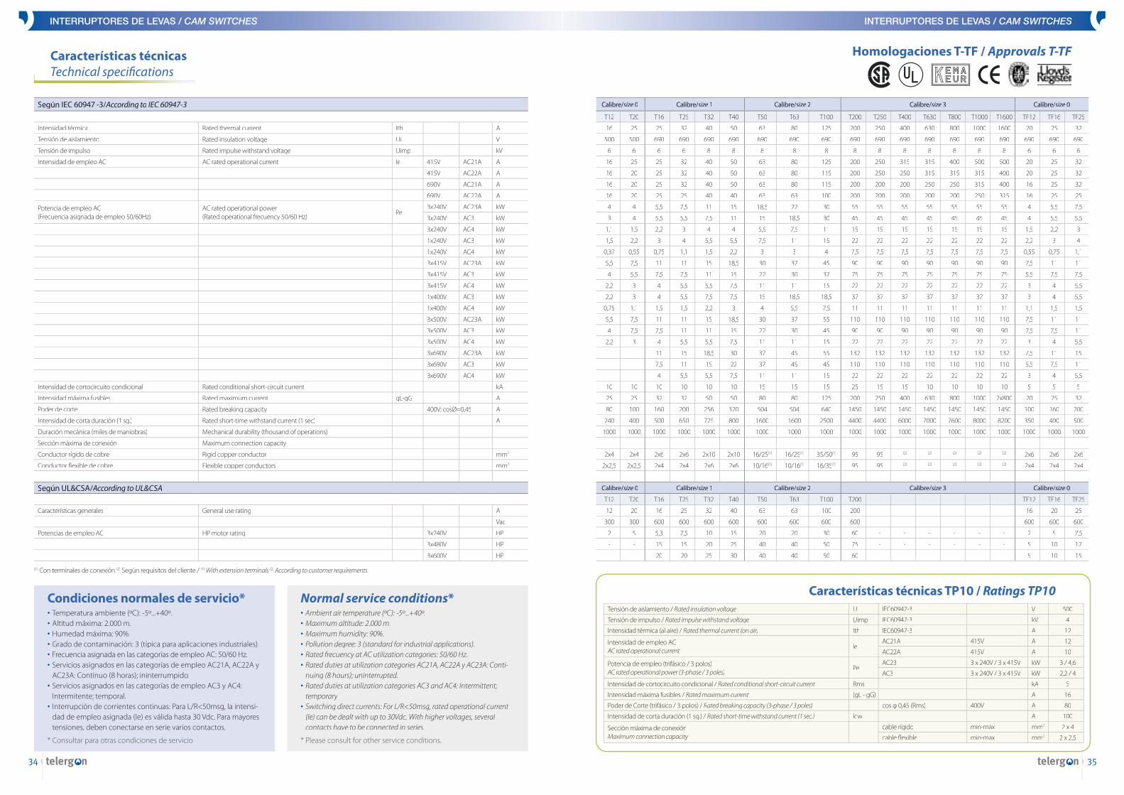
Características técnicasTechnical specifi cations
Según IEC 60947 -3/A/A/ ccording to IEC 60947-3IEC 60947-3IEC Calibre/sizeCalibre/sizeCalibre/ 0size 0size Calibre/sizeCalibre/sizeCalibre/ 1 Calibre/sizeCalibre/sizeCalibre/ 2 Calibre/sizeCalibre/sizeCalibre/ 3 Calibre/sizeCalibre/sizeCalibre/ 0size 0size
T12 T20 T16 T25 T32 T40 T50 T63 T100 T200 T250 T400 T630 T800 T1000 T1600 TF12 TF16 TF25
Intensidad térmica Rated thermal current Ith A 16 25 25 32 40 50 63 80 125 200 250 400 630 800 1000 1600 20 25 32
Tensión de aislamiento Rated insulation voltage Ui V 500 500 690 690 690 690 690 690 690 690 690 690 690 690 690 690 690 690 690
Tensión de impulso Rated impulse withstand voltage Uimp kV 6 6 6 6 8 8 8 8 8 8 8 8 8 8 8 8 6 6 6
Intensidad de empleo AC AC rated operational current Ie 415V AC21A A 16 25 25 32 40 50 63 80 125 200 250 315 315 400 500 500 20 25 32
415V AC22A A 16 20 25 32 40 50 63 80 115 200 250 250 315 315 315 400 20 25 32
690V AC21A A 16 20 25 32 40 50 63 80 115 200 200 200 250 250 315 400 16 25 32
690V AC22A A 16 20 25 25 40 40 63 63 100 200 200 200 200 200 250 315 16 25 25
Potencia de empleo AC(Frecuencia asignada de empleo 50/60Hz)
AC rated operational power(Rated operational frecuency 50/60 Hz)
Pe3x240V AC23A kW 4 4 5,5 7,5 11 15 18,5 22 30 55 55 55 55 55 55 55 4 5,5 7,5
3x240V AC3 kW 3 4 5,5 5,5 7,5 11 15 18,5 30 45 45 45 45 45 45 45 4 5,5 5,5
3x240V AC4 kW 1,1 1,5 2,2 3 4 4 5,5 7,5 11 15 15 15 15 15 15 15 1,5 2,2 3
1x240V AC3 kW 1,5 2,2 3 4 5,5 5,5 7,5 11 15 22 22 22 22 22 22 22 2,2 3 4
1x240V AC4 kW 0,37 0,55 0,75 1,1 1,5 2,2 3 3 4 7,5 7,5 7,5 7,5 7,5 7,5 7,5 0,55 0,75 1,1
3x415V AC23A kW 5,5 7,5 11 11 15 18,5 30 37 45 90 90 90 90 90 90 90 7,5 11 11
3x415V AC3 kW 4 5,5 7,5 7,5 11 15 22 30 37 75 75 75 75 75 75 75 5,5 7,5 7,5
3x415V AC4 kW 2,2 3 4 5,5 5,5 7,5 11 11 15 22 22 22 22 22 22 22 3 4 5,5
1x400V AC3 kW 2,2 3 4 5,5 7,5 7,5 15 18,5 18,5 37 37 37 37 37 37 37 3 4 5,5
1x400V AC4 kW 0,75 1,1 1,5 1,5 2,2 3 4 5,5 7,5 11 11 11 11 11 11 11 1,1 1,5 1,5
3x500V AC23A kW 5,5 7,5 11 11 15 18,5 30 37 55 110 110 110 110 110 110 110 7,5 11 11
3x500V AC3 kW 4 7,5 7,5 11 11 15 22 30 45 90 90 90 90 90 90 90 7,5 7,5 11
3x500V AC4 kW 2,2 3 4 5,5 5,5 7,5 11 11 15 22 22 22 22 22 22 22 3 4 5,5
3x690V AC23A kW - - 11 15 18,5 30 37 45 55 132 132 132 132 132 132 132 7,5 11 15
3x690V AC3 kW - - 7,5 11 15 22 37 45 45 110 110 110 110 110 110 110 5,5 7,5 11
3x690V AC4 kW - - 4 5,5 5,5 7,5 11 11 15 22 22 22 22 22 22 22 3 4 5,5
Intensidad de cortocircuito condicional Rated conditional short-circuit current kA 10 10 10 10 10 10 15 15 15 25 15 15 10 10 10 10 5 5 5
Intensidad máxima fusibles Rated maximum current gL-gG A 25 25 32 32 50 50 80 80 125 200 250 400 630 800 1000 2x800 20 25 32
Poder de corte Rated breaking capacity 400V; cosØ=0,45 A 80 100 160 200 256 320 504 504 640 1450 1450 1450 1450 1450 1450 1450 100 160 200
Intensidad de corta duración (1 sg.) Rated short-time withstand current (1 sec) A 240 400 500 650 725 800 1600 1600 2500 4400 4400 6000 7000 7600 8000 8200 350 400 500
Duración mecánica (miles de maniobras) Mechanical durability (thousand of operations) 1000 1000 1000 1000 1000 1000 1000 1000 1000 1000 1000 1000 1000 1000 1000 1000 1000 1000 1000
Sección máxima de conexión Maximum connection capacity
Conductor rígido de cobre Rigid copper conductor mm2 2x4 2x4 2x6 2x6 2x10 2x10 16/25(1) 16/25(1) 35/50(1) 95 95 (2) (2) (2) (2) (2) 2x6 2x6 2x6
Conductor fl exible de cobre Flexible copper conductors mm2 2x2,5 2x2,5 2x4 2x4 2x6 2x6 10/16(1) 10/16(1) 16/35(1) 95 95 (2) (2) (2) (2) (2) 2x4 2x4 2x4
Según UL&CSA/A/A/ ccording to UL&CSA Calibre/sizeCalibre/sizeCalibre/ 0size 0size Calibre/sizeCalibre/sizeCalibre/ 1 Calibre/sizeCalibre/sizeCalibre/ 2 Calibre/sizeCalibre/sizeCalibre/ 3 Calibre/sizeCalibre/sizeCalibre/ 0size 0size
T12 T20 T16 T25 T32 T40 T50 T63 T100 T200 - - - - - - TF12 TF16 TF25
Características generales General use rating A 12 20 16 25 32 40 63 63 100 200 - - - - - - 16 20 25
Vac 300 300 600 600 600 600 600 600 600 600 - - - - - - 600 600 600
Potencias de empleo AC HP motor rating 3x240V HP 2 5 5,3 7,5 10 15 20 20 30 60 - - - - - - 2 5 7,5
3x480V HP - - 15 15 20 25 40 40 50 75 - - - - - - 5 10 12
3x600V HP - - 20 20 25 30 40 40 50 60 - - - - - - 5 10 15
(1) Con terminales de conexión (2) Según requisitos del cliente / (1) With extension terminals (2) According to customer requirements
Condiciones normales de servicio*• Temperatura ambiente (ºC): -5º...+40º.• Temperatura ambiente (ºC): -5º...+40º.• • Altitud máxima: 2.000 m.• Humedad máxima: 90%.• Grado de contaminación: 3 (típica para aplicaciones industriales).• Frecuencia asignada en las categorías de empleo AC: 50/60 Hz.• Servicios asignados en las categorías de empleo AC21A, AC22A y
AC23A: Continuo (8 horas); ininterrumpido.• Servicios asignados en las categorías de empleo AC3 y AC4:
Intermitente; temporal.• Interrupción de corrientes continuas: Para L/R<50msg, la intensi-
dad de empleo asignada (Ie) es válida hasta 30 Vdc. Para mayores tensiones, deben conectarse en serie varios contactos.
* Consultar para otras condiciones de servicio
Normal service conditions*• Ambient air temperature (ºC): -5º...+40º.• Ambient air temperature (ºC): -5º...+40º.• • Maximum altitude: 2.000 m.• Maximum humidity: 90%.• Pollution degree: 3 (standard for industrial applications).• Rated frecuency at AC utilization categories: 50/60 Hz.• Rated duties at utilization categories AC21A, AC22A y AC23A: Conti-
nuing (8 hours); uninterrupted.• Rated duties at utilization categories AC3 and AC4: Intermittent;
temporary• Switching direct currents: For L/R<50msg, rated operational current
(Ie) can be dealt with up to 30Vdc. With higher voltages, several contacts have to be connected in series.
* Please consult for other service conditions.
Homologaciones T-TF / Approvals T-TF
Características técnicas TP10 / Ratings TP10Tensión de aislamiento / Rated insulation voltage Ui IEC60947-3 V 500
Tensión de impulso / Rated impulse withstand voltage Uimp IEC60947-3 kV 4
Intensidad térmica (al aire) / Rated thermal current (on air) Ith IEC60947-3 A 12
Intensidad de empleo ACAC rated operational current
IeAC21A 415V A 12
AC22A 415V A 10
Potencia de empleo (trifásico / 3 polos)AC rated operational power (3-phase / 3 poles)
PeAC23 3 x 240V / 3 x 415V kW 3 / 4,6
AC3 3 x 240V / 3 x 415V kW 2,2 / 4
Intensidad de cortocircuito condicional / Rated conditional short-circuit current Rms kA 5
Intensidad máxima fusibles / Rated maximum current (gL - gG) A 16
Poder de Corte (trifásico / 3 polos) / Rated breaking capacity (3-phase / 3 poles) cos φ 0,45 (Rms) 400V A 80
Intensidad de corta duración (1 sg.) / Rated short-time withstand current (1 sec.) Icw A 100
Sección máxima de conexiónMaximum connection capacity
cable rígido min-max mm2 2 x 4
cable fl exible min-max mm2 2 x 2,5

INTERRUPTORES DE LEVAS / CAM SWITCHES
36
• Interruptores y conmutadores de corte en carga ruptura brusca / Load break switch-disconnectors and changeover switches
• Interruptores y conmutadores con mando moto-rizado / Switch-disconnectors and changeover switches with motorized kit
• Interruptores con fusiblesSwitch-disconnectors fuses
• Aisladores / Insulators
• Finales de carrera / Limit switches
• Fusibles / Fuses
• Aparatos de medición / Measurement devices