interpss editor user guide_english_edition
DESCRIPTION
A complete InterPSS User GuideTRANSCRIPT

Main:InterPSS User Guide:Installation - InterPSS http://home.interpss.org:81/wiki/index.php?title=Main:InterPSS_User_G...
1 of 5 12/11/2007 6:01 AM
Links
InterPSS User Guide
InterPSS Project Overview
InterPSS Installation and Administration Guide
InterPSS Graphic Editor User Guide
InterPSS Loadflow User Guide
InterPSS Short Circuit User Guide
InterPSS Transient Stability User Guide
InterPSS Distribution System User Guide
InterPSS Grid Computing Solution
InterPSS Power Market Solution
Main:InterPSS User Guide:Installation
From InterPSS
InterPSS Installation and Administration Guide
This guide will walk you through InterPSS installation
process. It also outlines key administration steps to maintain
InterPSS user data.
Contents
1 Download InterPSS Release
2 Install InterPSS on Windows
2.1 Check Java installation
2.2 Unzip Installation File
2.3 Install InterPSS
2.4 Locale&UI Issue
3 Test InterPSS Installation
4 Install InterPSS Development Release
4.1 Full Development Release Installation
4.2 Apply Dev Release Patch
5 Document/Data Version Control/Backup
Download InterPSS Release
InerPSS download page Here (http://host.interpss.org/interpssdownload) has detailed information regarding InterPSS
download. You may also download InterPSS from SourceForge
(https://sourceforge.net/project/showfiles.php?group_id=165109 ) directly. There is also a development release hosted at
Here (http://home.interpss.org:8080/webdav/pub/InterPSSDevRelease/) , which has the latest features under
development, but may not be fully tested yet.
Install InterPSS on Windows
Please backup your existing InterPSS installation before proceeding to a new InterPSS installation.
Check Java installation
InterPSS is developed in the Java programming language. InterPSS depends on Java runtime environment from SUN
Micro System to run. To check your computer Java installation, launch a CMD window from Start/run/cmd. Type the
following command
Main:InterPSS User Guide:Installation - InterPSS http://home.interpss.org:81/wiki/index.php?title=Main:InterPSS_User_G...
2 of 5 12/11/2007 6:01 AM
Make sure that your Java version is "1.6.0" or above. If you do not have Java on your computer, please go to SUN Java
Distribution Site (http://www.java.com/en/download/manual.jsp) to download Java JDK 6.0 and install it to your
computer.
Unzip Installation File
InterPSS release distribution file is a zip file. Unzip the installation zip file to to a temporary directory in your computer.
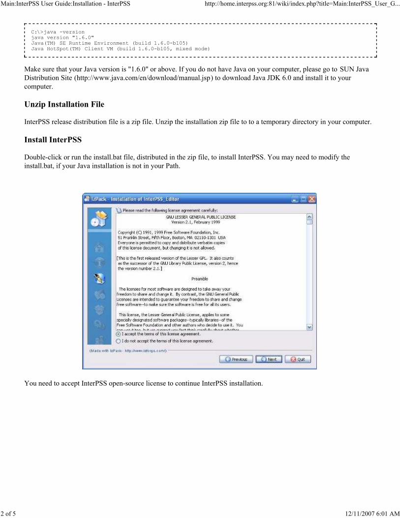
Install InterPSS
Double-click or run the install.bat file, distributed in the zip file, to install InterPSS. You may need to modify the
install.bat, if your Java installation is not in your Path.
You need to accept InterPSS open-source license to continue InterPSS installation.
C:\>java -version java version "1.6.0" Java(TM) SE Runtime Environment (build 1.6.0-b105) Java HotSpot(TM) Client VM (build 1.6.0-b105, mixed mode)
Main:InterPSS User Guide:Installation - InterPSS http://home.interpss.org:81/wiki/index.php?title=Main:InterPSS_User_G...
3 of 5 12/11/2007 6:01 AM
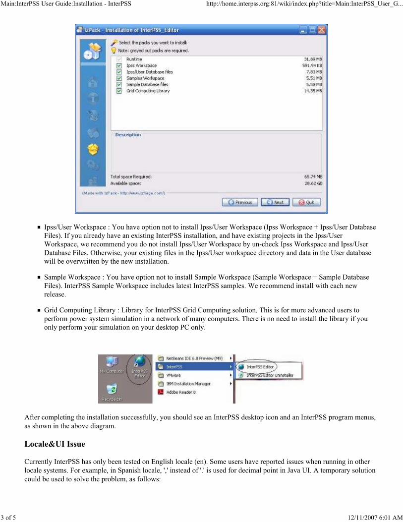
Ipss/User Workspace : You have option not to install Ipss/User Workspace (Ipss Workspace + Ipss/User Database
Files). If you already have an existing InterPSS installation, and have existing projects in the Ipss/User
Workspace, we recommend you do not install Ipss/User Workspace by un-check Ipss Workspace and Ipss/User
Database Files. Otherwise, your existing files in the Ipss/User workspace directory and data in the User database
will be overwritten by the new installation.
Sample Workspace : You have option not to install Sample Workspace (Sample Workspace + Sample Database
Files). InterPSS Sample Workspace includes latest InterPSS samples. We recommend install with each new
release.
Grid Computing Library : Library for InterPSS Grid Computing solution. This is for more advanced users to
perform power system simulation in a network of many computers. There is no need to install the library if you
only perform your simulation on your desktop PC only.
After completing the installation successfully, you should see an InterPSS desktop icon and an InterPSS program menus,
as shown in the above diagram.
Locale&UI Issue
Currently InterPSS has only been tested on English locale (en). Some users have reported issues when running in other
locale systems. For example, in Spanish locale, ',' instead of '.' is used for decimal point in Java UI. A temporary solution
could be used to solve the problem, as follows:

Main:InterPSS User Guide:Installation - InterPSS http://home.interpss.org:81/wiki/index.php?title=Main:InterPSS_User_G...
4 of 5 12/11/2007 6:01 AM
After the installation, in the installation root directory (where you can find ipss_edtior.jar), create a batch file, for
example run.bat, with following content:
Then use the batch file to run InterPSS.
Test InterPSS Installation
After the installation, you should be able to run InterPSS. Select the IEEE-14Bus.ipss project under the Samples folder,
you should see the following screen.
Install InterPSS Development Release
InterPSS development release has the latest features under development. These features may not be fully tested yet.
Please use it with care. You can download InterPSS dev release from Here
(http://home.interpss.org:8080/webdav/pub/InterPSSDevRelease/) .
start javaw -Duser.language=<your locale> -jar ipss_editor.jar

Main:InterPSS User Guide:Installation - InterPSS http://home.interpss.org:81/wiki/index.php?title=Main:InterPSS_User_G...
5 of 5 12/11/2007 6:01 AM
Full Development Release Installation
Please follow the following steps to install a new InterPSS development release:
backup your dev directory first!
Unzip the distribution file InterPSS_x.x.xx-Dev.zip to your dev release installation directory;
If there is a patch, unzip the patch file patch_x.x.xx-Dev.xx.zip to the same installation directory;
Make following changes to the run.bat:
Type run.bat to run the editor.
Apply Dev Release Patch
To apply dev release patch, just unzip the patch zip file to your dev release installation directory.
Document/Data Version Control/Backup
InterPSS documents and data are stored in the following directories
Ipss Workspace
Project documents : <install dir>/workspace
Project database data : <install>/db/IpssDB
Sample Workspace
Project documents : <install dir>/sample_ws
Project database data : <install>/db/SampleDB
You could backup and/or version control data in the Ipss Workspace to ensure that your work is fully recoverable in the
event of major computer failure.
Retrieved from "http://home.interpss.org:81/wiki/index.php?title=Main:InterPSS_User_Guide:Installation "
This page was last modified 18:42, 14 October 2007.
Content is available under GNU Free Documentation License 1.2.
- Change the first line c: to g: if you installed InterPSS on your G: drive.- Change cd c:\eclipse\geditor to cd <your installation location> - Change the Java command path <c:\jdk1.6.0\bin\java ...> to your Java installation location.
Main:InterPSS User Guide:GEditor Guide - InterPSS http://home.interpss.org:81/wiki/index.php?title=Main:InterPSS_User_G...
1 of 19 12/11/2007 6:03 AM
Links
InterPSS User Guide
InterPSS Project Overview
InterPSS Installation and Administration Guide
InterPSS Graphic Editor User Guide
InterPSS Loadflow User Guide
InterPSS Short Circuit User Guide
InterPSS Transient Stability User Guide
InterPSS Distribution System User Guide
InterPSS Grid Computing Solution
InterPSS Power Market Solution
Main:InterPSS User Guide:GEditor Guide
From InterPSS
InterPSS Graphic Editor User Guide
InterPSS provides a graphic editor for user to draw One-line diagram and enter study case data. Currently it has basic
functions to create a simple power system one-line diagram, input data, perform analysis and generate analysis reports.
The one-line diagram and data can be saved into a file and then reloaded into the editor for further analysis.
Contents
1 InterPSS Graphic Editor
2 InterPSS Workspace
3 Create InterPSS Project
4 Edit One-line Diagram
5 InterPSS Network Model
5.1 Network Object (Network JavaAPI)
5.2 Bus Object (Bus JavaAPI)
5.3 Branch Object (Branch JavaAPI)
6 Run Analysis
6.1 Custom Run Scripting
7 Analysis/Simulation Result
7.1 Result Annotation
7.2 Plot Transient Stability Simulation Result
7.3 Generate Report
8 Import Existing Project
8.1 Import InterPSS Project
8.2 Import Custom Data File
9 Getting Help
10 Debug InterPSS
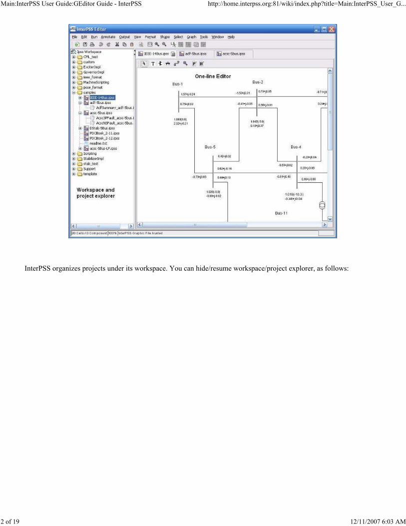
InterPSS Graphic Editor
As shown in the following diagram, the editor has two main areas: 1) Workspace/Project Explorer; and 2) One-line
graphic editor. You can work on multiple projects simultaneously. InterPSS uses a separate Java runtime thread to run
simulation cases, which means you can work on another case while waiting for the completion of a long running
analysis/simulation process, such as a transient stability simulation.
Main:InterPSS User Guide:GEditor Guide - InterPSS http://home.interpss.org:81/wiki/index.php?title=Main:InterPSS_User_G...
2 of 19 12/11/2007 6:03 AM
InterPSS organizes projects under its workspace. You can hide/resume workspace/project explorer, as follows:

Main:InterPSS User Guide:GEditor Guide - InterPSS http://home.interpss.org:81/wiki/index.php?title=Main:InterPSS_User_G...
3 of 19 12/11/2007 6:03 AM
The One-line diagram can be exported as PDF, SVG and other formats.
InterPSS Workspace
InterPSS uses computer file system and an internal database to persist its documents. These documents are organized
under the workspace concept. Currently InterPSS supports two workspaces: 1) Ipss/User Workspace; and 2) Sample
Workspace.

Main:InterPSS User Guide:GEditor Guide - InterPSS http://home.interpss.org:81/wiki/index.php?title=Main:InterPSS_User_G...
4 of 19 12/11/2007 6:03 AM
Ipss Workspace : For user projects. We recommend you put all your actual projects in this workspace. When you
perform a new InterPSS release installation, you have the option to keep this workspace untouched.
Sample Workspace : For InterPSS samples. This workspace will be constantly modified/updated by the InterPSS
development team with new samples to showcase InterPSS feature. We should only put your temporary data, for
example testing cases, in the workspace.
You can make switch between these two workspace by click the Select Workspace/* Workspace menu item freely
without need to exit InterPSS.
Under a workspace, projects are organized into project folders. Project related documents, such as reports, scripts, are put
under the parent project. As a user, you do not need to worry about how documents are internally organized and stored.
We do not recommend to make any change to the document file structure.
Create InterPSS Project
To create a new InterPSS project, first create a new project folder, for example, MyFolder. You can also add a new
project under an existing project folder.

Main:InterPSS User Guide:GEditor Guide - InterPSS http://home.interpss.org:81/wiki/index.php?title=Main:InterPSS_User_G...
5 of 19 12/11/2007 6:03 AM
To create a new InterPSS project into, for example, MyFolder, right click the project folder, and select Add InterPSS
Graphic File, as follows:
Enter project name : MyProject and click OK. At this time you can also create project based on an existing project, see
more in the late section on how to import an existing project into InterPSS.
After clicking the OK button, the InterPSS project data editor dialog box will automatically popup.
Enter necessary project info and click Save to complete the new project creation process. You should see the new project
listed in your workspace.

Main:InterPSS User Guide:GEditor Guide - InterPSS http://home.interpss.org:81/wiki/index.php?title=Main:InterPSS_User_G...
6 of 19 12/11/2007 6:03 AM
Edit One-line Diagram
InterPSS currently provides basic functions for user to create a power network for Loadflow, Short circuit, transient
stability or distribution system analysis. Currently available drawing tools are listed in the following figure:
Using the graphic drawing tools, one can quickly create a power network, such as the one showing in the following
diagram:

Main:InterPSS User Guide:GEditor Guide - InterPSS http://home.interpss.org:81/wiki/index.php?title=Main:InterPSS_User_G...
7 of 19 12/11/2007 6:03 AM
The "InterPSS Graphic Editor User Tips" (http://host.interpss.org/GraphicEditorUserTips.pdf ) document, contributed by
an InterPSS user, has more detailed information regarding how to use InterPSS graphic editor.
An asterisk in the one-line diagram, as shown in the above diagram, indicates that the network under editing has been
changed (dirty). You may want to save the project before moving to other tasks.
InterPSS Network Model
The foundation of InterPSS is an object-oriented power network model proposed in "Object-oriented Programming, C++
and Power System Simulation (http://home.interpss.org:8080/webdav/pub/PSS_OOP/OOP_CPP_and_PSS.doc) " (IEEE
Trans. on Power Systems, Vol.11, No.1, Feb. 1996 pp206-216). The basic idea could be summarized by the following
sentence (quoted from the original paper):
InterPSS assumes that all simulation algorithms are based on the node admittance Y-matrix. This also means that
InterPSS could be extended to implement any Y-matrix based power system simulation algorithm.
Network Object (Network JavaAPI
"A network container for the simulation purpose should be designed as if it is a place where buses can be defined, and branches can be connected between the defined buses to form a network."

Main:InterPSS User Guide:GEditor Guide - InterPSS http://home.interpss.org:81/wiki/index.php?title=Main:InterPSS_User_G...
8 of 19 12/11/2007 6:03 AM
(http://home.interpss.org:81/api/interpss/core/com/interpss/core/net/Network.html ) )
InterPSS divides power system simulation into two main categories (Application Type): 1) Transmission System and 2)
Distribution System. Transmission System concept is more applicable to high-voltage utility system studies where
network data are expressed in per unit. Distribution system concept is more applicable to medium and low-voltage
distribution system studies where network data are expressed in nameplate values, such as Ohms, or Housepower.
For transmission system application type, a network could be further categorized into three Network types:
ACLF – For describing steady state, positive sequence power networks. It is applicable to AC Loadflow, DC
Loadflow, Voltage stability and other analysis where steady-state positive sequence power network data are
needed.
ACSC – For describing steady state power networks with positive, negative and zero sequence network data. It is
applicable to Short Circuit analysis.
TranStability – For describing dynamic power networks for transient stability simulation.
These three types of networks have an inheritance relationship, as shown in the above diagram. It is assumed that all
transmission system network data are entered based on the BaseKVA (Base Kva) and BaseFreq (Base system frequency)
defined in the InterPSS project dialog box.
Please note: after a project has been created, its application type cannot be changed. You cannot change, for example, a
transmission system to a distribution system, since their underlaying data structures are quite different. Within the same
application type, you can only change the network type downward in the inheritance hierarchy, for example, from ACLF
to ACSC network. Changing from ACSC network to ACLF network will result data loss, which is the reason why it is

Main:InterPSS User Guide:GEditor Guide - InterPSS http://home.interpss.org:81/wiki/index.php?title=Main:InterPSS_User_G...
9 of 19 12/11/2007 6:03 AM
not allowed. Please note: you can perform Loadflow analysis on an ACSC network, if Loadflow data has been entered
into the network.
Bus/Branch inside InterPSS simulation model are modeled as objects. These objects have types, such as AclfBus,
AclfBranch, applicable to different type studies, such as Loadflow. However, these objects share certain common
features, as follows:
Bus Object (Bus JavaAPI
(http://home.interpss.org:81/api/interpss/core/com/interpss/core/net/Bus.html ) )
A unique bus sequence number, starting from 0001, will be assigned by InterPSS to each bus object when it is created
and added on to the One-line diagram. This bus sequence number is used as the bus object id. A bus object also has
BusName (optional), Base Voltage, Area number, Zone number. If the In Service checkbox is unchecked, the Bus object
will not participate in the simulation.
To retrieve the bus object from it parent containing network object, we can write the following Java statement:
where, net is a Network object, "0001" is the Bus object id.
Branch Object (Branch JavaAPI
(http://home.interpss.org:81/api/interpss/core/com/interpss/core/net/Branch.html ) )
A branch object, in the InterPSS simulation model, is always connected between two buses - from-bus and to-bus. When
you draw a branch from one bus to another bus, system will automatically connect the branch object to the two buses.
After the branch creation, the connection relationship cannot be modified. InterPSS branch id takes the following format:
For example, branch id 0001->0002(1) indicates the branch connected to from-bus (0001) and to-bus(0002). Its circuit
number is 1.
To retrieve a branch object from it parent containing network object, there are three ways, as follows:
Bus bus = net.getBus("0001");
fromBusId->toBusId(Branch Circuit number)

Main:InterPSS User Guide:GEditor Guide - InterPSS http://home.interpss.org:81/wiki/index.php?title=Main:InterPSS_User_G...
10 of 19 12/11/2007 6:03 AM
where, net is the parent Network object, "0001" is the Branch from bus object id, "0002" is the Branch to bus object id
and '1' branch circuit number.
A unique branch sequence number, starting from 0001, will be assigned by InterPSS to a branch object when it is created
and added on to the One-line diagram. A branch object also has BranchName (optional), Area number and Zone number.
If the In Service checkbox is unchecked, the Branch will be treated as an open branch in the simulation.
Please note:
InterPSS power system object model allows multiple parallel branches be defined between two buses. However, the
current One-line diagram can only allow you to draw one branch between two buses. The limitation will be
removed in the near future.
InterPSS has no limit on number of buses and branches. Memory necessary to store simulation information is
dynamic allocated during the simulation process. Also, it will only allocate memory for the exact network size. For
example, if you have a 5-bus system with 4 branches, InterPSS will only allocate memory for 5 Bus objects and for
4 Branch objects.
Run Analysis
After creating a project and entering data, you can run analysis. Depending on the type of network created, analysis menu
items will be enabled for you to perform appropriate analysis.
Assume you selected run Loadflow Analysis, you will be presented with the following dialog box:
Branch branch = net.getBranch("0001", "0002"); // use this approach when there is no parallel branch between two buses Branch branch = net.getBranch("0001", "0002", "1"); // "1" is the branch circuit number Branch branch = net.getBranch("0001->0002(1)"); // retrieve branch by branch id
An in-depth discussion of InterPSS power system simulation model can be found at InterPSS Simulation Framework Please follow the API link to read InterPSS Java API document, where you can find InterPSS programming details, which will help you to understand InterPSS from programming perspective.

Main:InterPSS User Guide:GEditor Guide - InterPSS http://home.interpss.org:81/wiki/index.php?title=Main:InterPSS_User_G...
11 of 19 12/11/2007 6:03 AM
Select run options and enter necessary data, then click the Run button to run Loadflow analysis. A Loadflow summary
will be presented after successfully completing the run.
If the run process is rather long, such as a transient stability simulation, the progress bar will display the percentage of
simulation completed.

Main:InterPSS User Guide:GEditor Guide - InterPSS http://home.interpss.org:81/wiki/index.php?title=Main:InterPSS_User_G...
12 of 19 12/11/2007 6:03 AM
In some unusual cases, the simulation thread is continuously running. You can click the green button to stop.
Custom Run Scripting
InterPSS allows you to run its simulation engine in your own way by providing your own custom run scripts.
Please see How to Script Custom Analysis Run for details.
Analysis/Simulation Result
InterPSS analysis/simulation results could be output in different format, including One-line diagram annotation, curve
plotting and InterPSS report.
Result Annotation
InterPSS currently supports annotate Loadflow and Short Circuit results onto the One-line diagram after a simulation run.

Main:InterPSS User Guide:GEditor Guide - InterPSS http://home.interpss.org:81/wiki/index.php?title=Main:InterPSS_User_G...
13 of 19 12/11/2007 6:03 AM
The following is sample of Loadflow result annotation.
You can use mouse to adjust annotation text position on the One-line diagram. InterPSS will remember the location
change. You can also select the clear annotation menu item to clear the annotation text on the diagram.
InterPSS in the future will allow user to have more control over the annotation content and style.
Plot Transient Stability Simulation Result

Main:InterPSS User Guide:GEditor Guide - InterPSS http://home.interpss.org:81/wiki/index.php?title=Main:InterPSS_User_G...
14 of 19 12/11/2007 6:03 AM
After completing a transient stability simulation, right-click a bus, you can have choice to plot any state variable
associated with the bus.
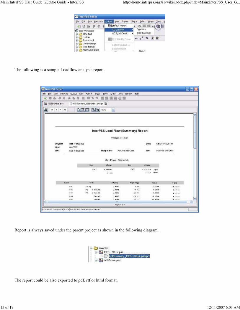
Generate Report
After an analysis run, appropriate reports could be generated.
Main:InterPSS User Guide:GEditor Guide - InterPSS http://home.interpss.org:81/wiki/index.php?title=Main:InterPSS_User_G...
15 of 19 12/11/2007 6:03 AM
The following is a sample Loadflow analysis report.
Report is always saved under the parent project as shown in the following diagram.
The report could be also exported to pdf, rtf or html format.

Main:InterPSS User Guide:GEditor Guide - InterPSS http://home.interpss.org:81/wiki/index.php?title=Main:InterPSS_User_G...
16 of 19 12/11/2007 6:03 AM
InterPSS report is template driven. You can create your own report template and plug into InterPSS to create your own
custom report. Please see How to Customize InterPSS Report for details.
Import Existing Project
Import InterPSS Project
When you create a new InterPSS project, you can optionally import an existing InterPSS project. InterPSS will make a
copy of the existing InterPSS project file *.ipss and import the copy into the new project.
Import Custom Data File
To import a custom data file, such a PSS/E raw file, right-click a project folder, the select Add/Add Custom Data File.
Currently, InterPSS supports the following custom file formats.

Main:InterPSS User Guide:GEditor Guide - InterPSS http://home.interpss.org:81/wiki/index.php?title=Main:InterPSS_User_G...
17 of 19 12/11/2007 6:03 AM
The following is an example to import a date file in IEEE Common Format into InterPSS.
Getting Help
You can access InterPSS help information under the Help menu. For example, by clicking the User Guide -> English
User Guide, InterPSS will launch your default browser and load this user guide into the browser, as shown in the
following figure.
InterPSS uses custom data file adapters to import data in a particular formal into InterPSS. You can find more information on this subject by reading the InterPSS Custom Data File Adapter Source Code (http://interpss.googlecode.com/svn/trunk/ipss.plugin/src/org/interpss/custom/exchange/ file adapter and plugin to InterPSS to import your data into InterPSS. The InterPSS Development Guide Develop Custom Data File Adapter could walk you through steps to implement such a adapter.

Main:InterPSS User Guide:GEditor Guide - InterPSS http://home.interpss.org:81/wiki/index.php?title=Main:InterPSS_User_G...
18 of 19 12/11/2007 6:03 AM
You can also get to InterPSS Support site by using the menu items under the Support menu.
Debug InterPSS
Sometime your simulation results may be obviously wrong. Chances are that your input data may not be entered
correctly. While InterPSS tries to check input data before running an analysis, it is impossible to catch all possible
mistakes. At this point, you can send your case to the InterPSS Support (mailto:[email protected]) or you can debug
yourself.
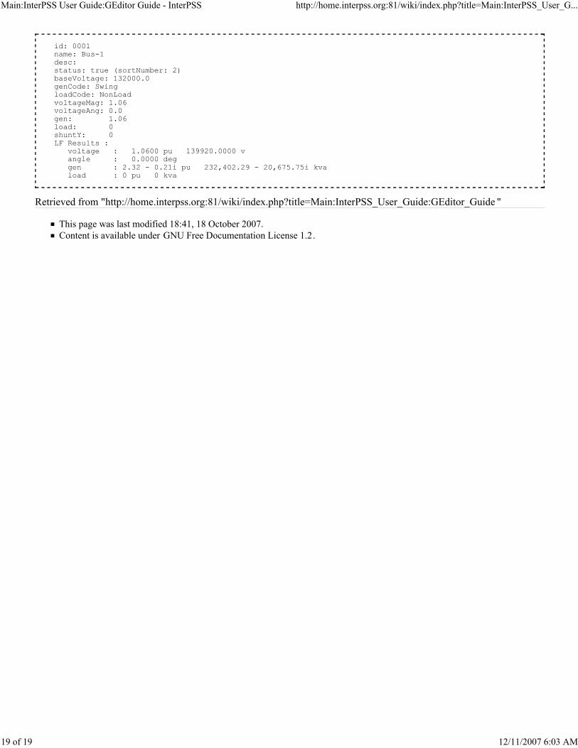
By clicking the Tools/Debug/SimuContextInfo, you can list the states of all objects of the current project in memory.
You may need to consult InterPSS Core API (http://home.interpss.org:81/api/interpss/core/index.html ) to interpret the
information. For example, the following is AclfBus object info:
Main:InterPSS User Guide:GEditor Guide - InterPSS http://home.interpss.org:81/wiki/index.php?title=Main:InterPSS_User_G...
19 of 19 12/11/2007 6:03 AM
Retrieved from "http://home.interpss.org:81/wiki/index.php?title=Main:InterPSS_User_Guide:GEditor_Guide "
This page was last modified 18:41, 18 October 2007.
Content is available under GNU Free Documentation License 1.2.
id: 0001 name: Bus-1 desc: status: true (sortNumber: 2) baseVoltage: 132000.0 genCode: Swing loadCode: NonLoad voltageMag: 1.06 voltageAng: 0.0 gen: 1.06 load: 0 shuntY: 0 LF Results : voltage : 1.0600 pu 139920.0000 v angle : 0.0000 deg gen : 2.32 - 0.21i pu 232,402.29 - 20,675.75i kva load : 0 pu 0 kva

Main:InterPSS User Guide:Loadflow Guide - InterPSS http://home.interpss.org:81/wiki/index.php?title=Main:InterPSS_User_G...
1 of 17 12/11/2007 6:04 AM
Links
InterPSS User Guide
InterPSS Project Overview
InterPSS Installation and Administration Guide
InterPSS Graphic Editor User Guide
InterPSS Loadflow User Guide
InterPSS Short Circuit User Guide
InterPSS Transient Stability User Guide
InterPSS Distribution System User Guide
InterPSS Grid Computing Solution
InterPSS Power Market Solution
Main:InterPSS User Guide:Loadflow Guide
From InterPSS
InterPSS Loadflow User Guide
Load flow is one of the most commonly use power system analyses. It is also the foundation for other types of analysis
and simulation. InterPSS loadflow algorithm can be summarized as follows:
The mismatch is computed based on bus Y-matrix and bus voltage. Currently, InterPSS loadflow implementation
includes Newton Raphson (NR) method, Fast-Decoupled (PQ) method and Guess Siedel (GS) method. It also features
Functional Load, PV Bus Limit control, PQ Bus Limit control, Remote Q adjustment, Transformer tap adjustment, and
Phase-shifting angle adjustment.
For a set of specified bus voltage (magnitude and angle) and/or bus generation (Pg, Qg) at generator buses and specified load (Pl,Ql) at load buses, find a set of bus voltage by iterative computation steps, such that the power mismatch between specified bus quantities and calculated bus quantities is within a user specified convergence tolerance.

Main:InterPSS User Guide:Loadflow Guide - InterPSS http://home.interpss.org:81/wiki/index.php?title=Main:InterPSS_User_G...
2 of 17 12/11/2007 6:04 AM
Contents
1 Create Loadflow Project
1.1 Project/Network Data (AclfNetwork JavaAPI)
1.2 Bus Data (AclfBus JavaAPI)
1.3 Branch Data (AclfBranch JavaAPI)
2 Run Loadflow Analysis
3 Loadflow Summary Display
4 Loadflow Result Annotation
5 Loadflow Report
6 Loadflow Lab
6.1 Step-by-step Run
6.2 Applying Adjustment/Control
7 Advanced Loadflow Adjustment/Control
7.1 Functional Load (FunctionLoad JavaAPI)
7.2 PV Bus Limit Adjustment (PVBusLimit JavaAPI)
7.3 PQ Bus Limit Control (PQBusLimit JavaAPI)
7.4 Remote Q Adjustment (RemoteQBus JavaAPI)
7.5 Transformer Tap Adjustment (TapControl JavaAPI)
7.6 Phase-Shift Transformer Adjustment (PSXfrPControl JavaAPI)
7.7 Area Interchange Power Control (AreaInterchangeController JavaAPI)
Create Loadflow Project
If you are new to the InterPSS graphic One-line editor, please read the InterPSS Graphic Editor User Guide to get familar
with the basic steps to create an InterPSS project.
Project/Network Data (AclfNetwork JavaAPI
(http://home.interpss.org:81/api/interpss/core/com/interpss/core/aclf/AclfNetwork.html ) )
To define a Loadflow project, select Transmission application type and ACFL network type.
Main:InterPSS User Guide:Loadflow Guide - InterPSS http://home.interpss.org:81/wiki/index.php?title=Main:InterPSS_User_G...
3 of 17 12/11/2007 6:04 AM
Description:Description of the project.BaseKVA:Base KVA for the Per Unit system for the project.
BaseFreq:Base Frequency in Hz for the project.Include adjustments/Controls:Include advanced adjustment and control in the analysis.
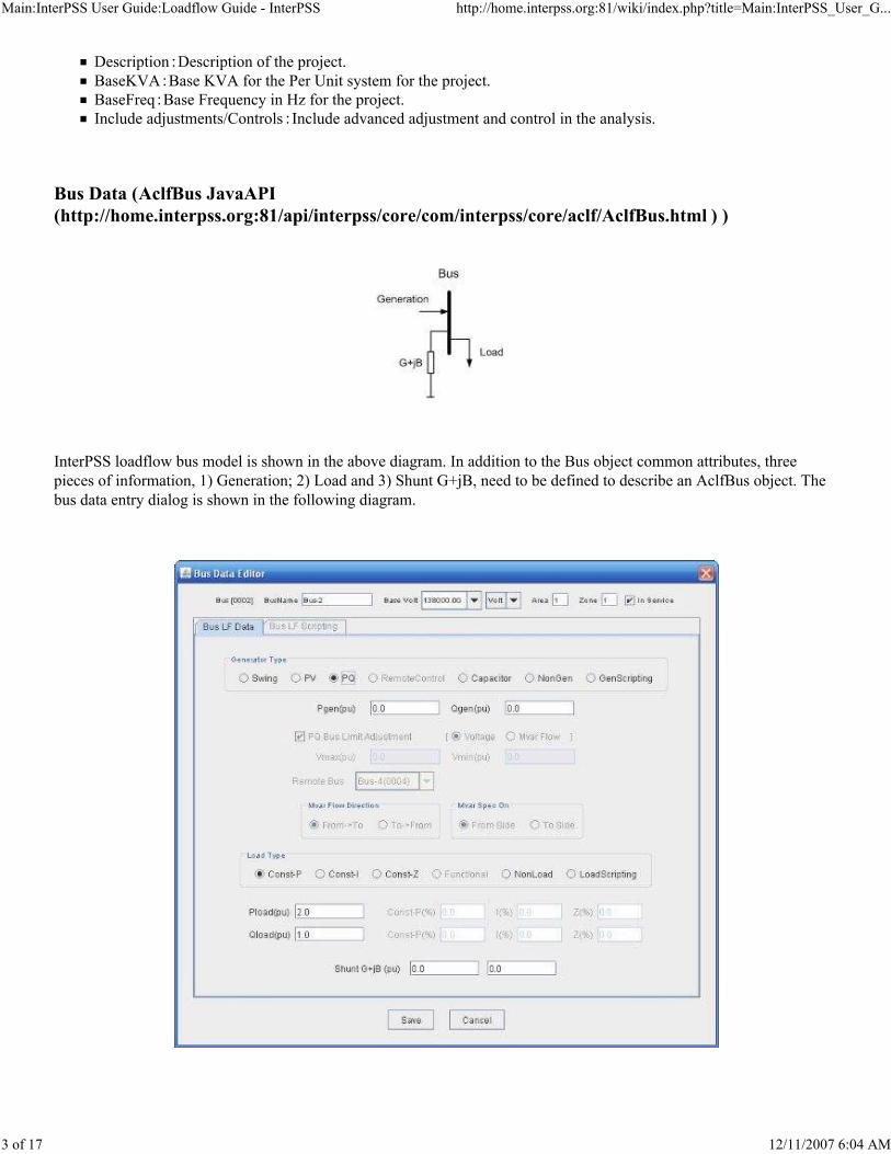
Bus Data (AclfBus JavaAPI
(http://home.interpss.org:81/api/interpss/core/com/interpss/core/aclf/AclfBus.html ) )
InterPSS loadflow bus model is shown in the above diagram. In addition to the Bus object common attributes, three
pieces of information, 1) Generation; 2) Load and 3) Shunt G+jB, need to be defined to describe an AclfBus object. The
bus data entry dialog is shown in the following diagram.

Main:InterPSS User Guide:Loadflow Guide - InterPSS http://home.interpss.org:81/wiki/index.php?title=Main:InterPSS_User_G...
4 of 17 12/11/2007 6:04 AM
Swing - Swing/Slack generation bus
Vspec(pu):Bus voltage magnitude
Angle(deg):Bus voltage anglePV - PV generation bus
Pgen(pu):Generator active powerVspec(pu):Bus voltage magnitude
PQ - PQ generation bus
Pgen(pu):Generator active powerQgen(pu):Generator reactive power
Capacitor - Capacitor bus
Qcap(pu):Rated capacitor reactive power. The reactive power is treated as an impedance in the Loadflow
calculation.
Non-Gen : None generator
GenScripting : Bus custom model scripting. See How to Script InterPSS Bus/Branch Object for details.
Const-P:Constant power loadConst-I:Constant current loadConst-Z:Constant impedance load
NonLoad:none load busLoadScripting : Bus custom model scripting. See How to Script InterPSS Bus/Branch Object for details.
Pload(pu):Bus load active powerQload(pu):Bus load reactive power
Shunt G+jB(pu):Bus shunt admittance;
The other disabled fields on the Bus data dialog box are for advanced Loadflow features. They will be enabled when the
Include adjustments/Controls choice in the project data panel is selected.
Branch Data (AclfBranch JavaAPI
(http://home.interpss.org:81/api/interpss/core/com/interpss/core/aclf/AclfBranch.html ) )
Line Branch Model
Transformer Branch Model

Main:InterPSS User Guide:Loadflow Guide - InterPSS http://home.interpss.org:81/wiki/index.php?title=Main:InterPSS_User_G...
5 of 17 12/11/2007 6:04 AM
Phase Shifting Transformer Branch Model
InterPSS loadflow branch models are shown in the above diagrams. Please note: InterPSS simulation model also supports
a phase-shift angle at the to-bus side also. For more details, see Phase-shift Transformer Java API
(http://home.interpss.org:81/api/interpss/core/com/interpss/core/aclf/PSXfrAdapter.html )
To define a Line branch, select Branch Type - Line
R(pu):Line resistanceX(pu):Line reactance1/2B(pu):Half line charging admittance
MvaRating1:Branch Mva rating for violation check
MvaRating2:Branch Mva rating for violation check
MvaRating3:Branch Mva rating for violation check
To define a Transformer branch, select Branch Type - XFormer. The following additional fields need to be defined:
From TurnRatio(pu):From bus side transformer turn ratio
To TurnRatio(pu):To bus side transformer turn ratio
To define a Phase-shifting Transformer branch, select Branch Type - PhaseShift-Xfr. The following additional fields
need to be defined:
Shift Angle(deg):From bus side phase-shifting angle. From-side bus voltage is shifted by the angle value.

Main:InterPSS User Guide:Loadflow Guide - InterPSS http://home.interpss.org:81/wiki/index.php?title=Main:InterPSS_User_G...
6 of 17 12/11/2007 6:04 AM
BranchScripting - See How to Script InterPSS Bus/Branch Object for details.
Run Loadflow Analysis
When your project has loadflow information, no matter it is Transmission system or Distribution system, ACLF, ACSC
or TranStability network type, the Loadflow Analysis menu item will allow you to perform a loadflow analysis run.
Casename:Run case name.
Description:Description for the caseNR: Newton-Raphson Method
PQ: Fast Decoupled Method
GS: Gauss-Seidel Method
Error tolerance:Error tolerance for loadflow convergence checkMax iteration:Maximum iterations for the run.
Initialize Bus Voltage:Initialize bus voltage before running the case. InterPSS holds loadflow results in memory.
Therefore, a loadflow run could continue from a previous run or start from flesh by initializing the bus voltage.
Show Loadflow Summary:If checked, the loadflow summary information will be displayed after a Loadflow run.

Main:InterPSS User Guide:Loadflow Guide - InterPSS http://home.interpss.org:81/wiki/index.php?title=Main:InterPSS_User_G...
7 of 17 12/11/2007 6:04 AM
You can find more detailed information about InterPSS Loadflow algorithm by examining the InterPSS Loadflow
Algorithm API (http://home.interpss.org:81/api/interpss/core/com/interpss/core/algorithm/LoadflowAlgorithm.html ) .
Loadflow Summary Display
If Show Loadflow Summary option is selected when running a loadflow analysis, the summary will be display, as shown
in the following figure.
By clicking the Bus Style option, the summary can be displayed in the IEEE Bus Style Format, as follows:

Main:InterPSS User Guide:Loadflow Guide - InterPSS http://home.interpss.org:81/wiki/index.php?title=Main:InterPSS_User_G...
8 of 17 12/11/2007 6:04 AM
You can click the SaveAs button to save the result to a text file.
Loadflow Result Annotation
Loadflow results will be annotated on the One-line diagram after a loadflow run.
Loadflow Report

Main:InterPSS User Guide:Loadflow Guide - InterPSS http://home.interpss.org:81/wiki/index.php?title=Main:InterPSS_User_G...
9 of 17 12/11/2007 6:04 AM
Loadflow report can be generated after a loadflow run.
InterPSS report is template driven. You can create your own report template and plug into InterPSS to create your own
custom report. Please see How to Customize InterPSS Report for details.
Loadflow Lab
In most cases, you can get a converged loadflow solution by applying the NR, PQ or GS method. However, there may be
situations where the available methods cannot produce a converged loadflow solution, because of data entering errors or
ill-conditioned operation conditions. In such situation, you may want to find out the reason by "looking" into the
loadflow calculation process to diagnosis the problem.

Main:InterPSS User Guide:Loadflow Guide - InterPSS http://home.interpss.org:81/wiki/index.php?title=Main:InterPSS_User_G...
10 of 17 12/11/2007 6:04 AM
Loadflow is a non-linear problem. There is no math equation/method to exactly tell you what is the problem, at least we
have not found such equation/method yet. What InterPSS provides is a new concept - Loadflow Lab, which allows you to
run loadflow step-by-step, using different method at your choice, and applying loadflow adjustment/control at any time
you want. The design goal of InterPSS Loadflow Lab is to provide an environment for you to tune your network to get a
converge loadflow solution, as if you were sitting in a power system laboratory and adjusting control buttons to turn a
power system to a desired operating condition.
Adjustment, such as the Remote Q Adjustment, applies certain adjustment of, for example, bus generator Q, to maintain
voltage at a specified bus. The adjustment amount is calculated by InterPSS using sensitivity analysis. Sensitivity
analysis is a linearization prediction, trying to predict the non-linear system behaviour using sensitivity factor(s).
InterPSS allows you to control the adjustment amount by specifying a change multiplying factor.
Step-by-step Run
By clicking the "NR>" button, a NR step will be applied. You can watch the Power Mismatch change after the click.
Normally, the mismatch will decrease. In case, the mismatch increases, click Details to find out the bus(s) with large
mismatch to diagnosis the problem.

Main:InterPSS User Guide:Loadflow Guide - InterPSS http://home.interpss.org:81/wiki/index.php?title=Main:InterPSS_User_G...
11 of 17 12/11/2007 6:04 AM
NR> : Run a Newton-Raphson method step
PQ-P> : Run a Fast-Decoupled method P calculation step
PQ-Q> : Run a Fast-Decoupled method Q calculation step
GS> : Run a Gauss-Seidel method step
Reset : Reset the network to its initial condition (voltage = 1.0)
Applying Adjustment/Control
When you have active adjustment/control, you will see enabled buttons, which allows you to apply all
adjustment/control(s) in a category or an individual adjustment/control. During the calculation process, an
adjustment/control could be turned off. For example, a PV Bus Limit control will be turned off when a violation found
and the bus is turned to a PQ Bus.
The status window will display internal messages indicating actions taken by InterPSS simulation engine. For example,
in the following case, PV Bus has been turned to PQ Bus because of limit violation.
Advanced Loadflow Adjustment/Control
When the "Include adjustment/Controls" option in the project data dialog is selected, InterPSS will allow you to define
some advanced adjustment/control in your loadflow study.

Main:InterPSS User Guide:Loadflow Guide - InterPSS http://home.interpss.org:81/wiki/index.php?title=Main:InterPSS_User_G...
12 of 17 12/11/2007 6:04 AM
The following is a summary of this advanced feature. More detailed information can be found at AC Loadflow Analysis
Reference Manual
(http://home.interpss.org:81/wiki/index.php?title=Main_:_InterPSS_Reference_:_Aclf#Advanced_Loadflow_Adjustment.2FControl
.
Functional Load (FunctionLoad JavaAPI
(http://home.interpss.org:81/api/interpss/core/com/interpss/core/aclfadj/FunctionLoad.html ) )

Main:InterPSS User Guide:Loadflow Guide - InterPSS http://home.interpss.org:81/wiki/index.php?title=Main:InterPSS_User_G...
13 of 17 12/11/2007 6:04 AM
Functional load allows you to model a bus voltage dependent non-linear load
PV Bus Limit Adjustment (PVBusLimit JavaAPI
(http://home.interpss.org:81/api/interpss/core/com/interpss/core/aclfadj/PVBusLimit.html ) )
PV Bus Limit Adjustment allows you to define Qmax and Qmin for a PV Bus. If during the loadflow calculation process,
the Q required to support the PV Bus voltage (Vspec) exceeds the limit, the bus will be changed to a PQ Bus with bus Q
Pload = Pload(0) * [ Const-P-factor + Const-I-factor * Voltage + Const-Z-factor * Voltage^2 ] Qload = Qload(0) * [ Const-P-factor + Const-I-factor * Voltage + Const-Z-factor * Voltage^2 ]
Main:InterPSS User Guide:Loadflow Guide - InterPSS http://home.interpss.org:81/wiki/index.php?title=Main:InterPSS_User_G...
14 of 17 12/11/2007 6:04 AM
= Qmax or Qmin.
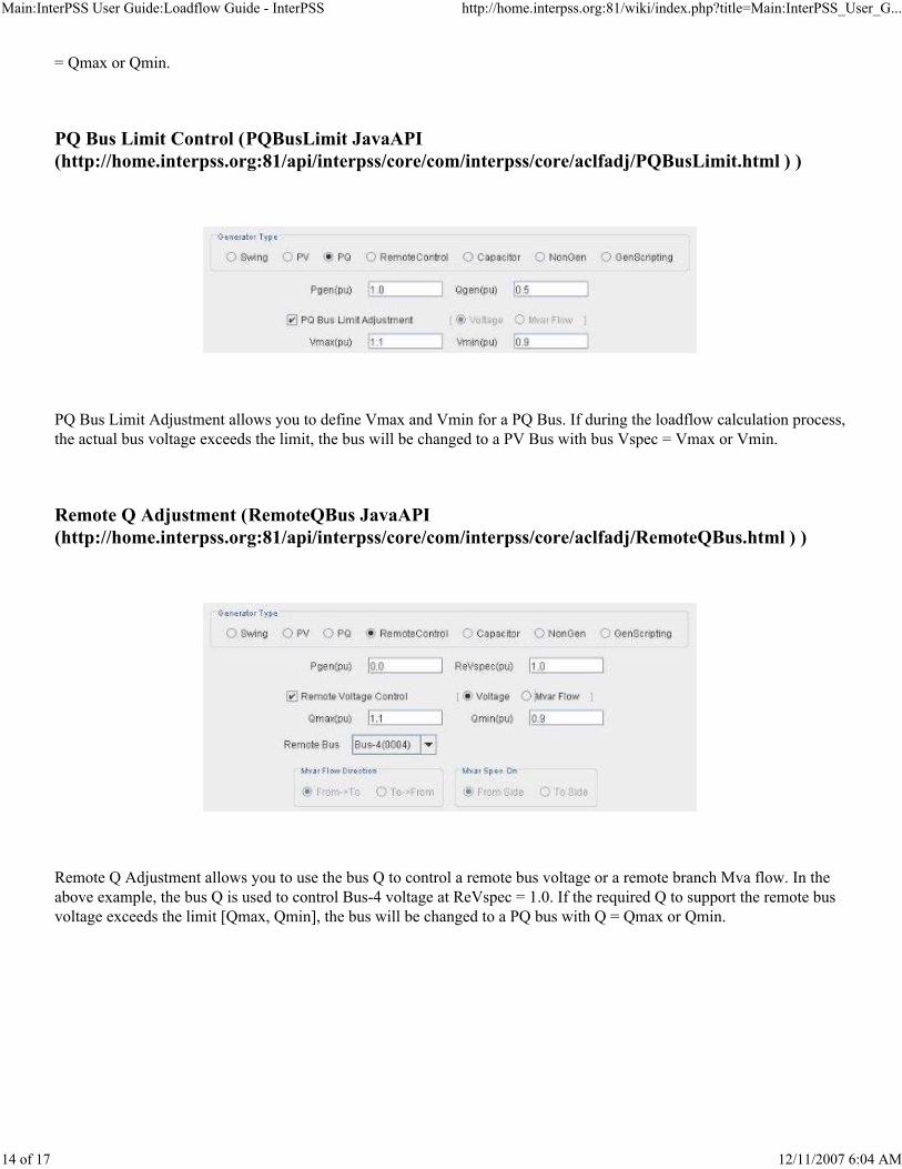
PQ Bus Limit Control (PQBusLimit JavaAPI
(http://home.interpss.org:81/api/interpss/core/com/interpss/core/aclfadj/PQBusLimit.html ) )
PQ Bus Limit Adjustment allows you to define Vmax and Vmin for a PQ Bus. If during the loadflow calculation process,
the actual bus voltage exceeds the limit, the bus will be changed to a PV Bus with bus Vspec = Vmax or Vmin.
Remote Q Adjustment (RemoteQBus JavaAPI
(http://home.interpss.org:81/api/interpss/core/com/interpss/core/aclfadj/RemoteQBus.html ) )
Remote Q Adjustment allows you to use the bus Q to control a remote bus voltage or a remote branch Mva flow. In the
above example, the bus Q is used to control Bus-4 voltage at ReVspec = 1.0. If the required Q to support the remote bus
voltage exceeds the limit [Qmax, Qmin], the bus will be changed to a PQ bus with Q = Qmax or Qmin.

Main:InterPSS User Guide:Loadflow Guide - InterPSS http://home.interpss.org:81/wiki/index.php?title=Main:InterPSS_User_G...
15 of 17 12/11/2007 6:04 AM
You can also use the bus Q to control reactive Mar flow on a remote branch. For example, in the above diagram, the bus
Q is used to control reactive power flow on branch Bus2->Bus4. The Mar flow direction is From->To and Mar is
measured at the to-bus side.
Transformer Tap Adjustment (TapControl JavaAPI
(http://home.interpss.org:81/api/interpss/core/com/interpss/core/aclfadj/TapControl.html ) )
You can use transformer tap to control a bus voltage. The bus could be the terminal bus of the transformer or any remote

Main:InterPSS User Guide:Loadflow Guide - InterPSS http://home.interpss.org:81/wiki/index.php?title=Main:InterPSS_User_G...
16 of 17 12/11/2007 6:04 AM
bus in the network. You need to specify the bus to be voltage-controlled is on the transformer from-bus side or to-bus
side, and the control tap is on the from-side or to-side. Also, limit [max/min turn ratio] and change step length need to be
specified. If the Step = 0.0, it is assumed that the transformer tap could be adjusted continuously.
You can also use transformer tap to control reactive Mar flow on the transformer branch.
Phase-Shift Transformer Adjustment (PSXfrPControl JavaAPI
(http://home.interpss.org:81/api/interpss/core/com/interpss/core/aclfadj/PSXfrPControl.html ) )
You can use phase-shift angle to control power flow on the phase-shift transformer. You need to specify power control
side (From Side or To Side) and power flow direction (From->To or To-From). Angle control is within the limit

Main:InterPSS User Guide:Loadflow Guide - InterPSS http://home.interpss.org:81/wiki/index.php?title=Main:InterPSS_User_G...
17 of 17 12/11/2007 6:04 AM
[AngleMax, AngleMin].
Area Interchange Power Control (AreaInterchangeController JavaAPI
(http://home.interpss.org:81/api/interpss/core/com/interpss/core/aclfadj/AreaInterchangeController.html
)
(Todo ...)
Retrieved from "http://home.interpss.org:81/wiki/index.php?title=Main:InterPSS_User_Guide:Loadflow_Guide "
This page was last modified 03:22, 22 September 2007.
Content is available under GNU Free Documentation License 1.2.

Main:InterPSS User Guide:ShortCircuit Guide - InterPSS http://home.interpss.org:81/wiki/index.php?title=Main:InterPSS_User_G...
1 of 9 12/11/2007 6:05 AM
Links
InterPSS User Guide
InterPSS Project Overview
InterPSS Installation and Administration Guide
InterPSS Graphic Editor User Guide
InterPSS Loadflow User Guide
InterPSS Short Circuit User Guide
InterPSS Transient Stability User Guide
InterPSS Distribution System User Guide
InterPSS Grid Computing Solution
InterPSS Power Market Solution
Main:InterPSS User Guide:ShortCircuit Guide
From InterPSS
InterPSS Short Circuit User Guide
InterPSS short circuit implementation includes 3-Phase, Line to Ground, Line to Line and Line-Line-Ground faults.
The fault can be defined at a bus or on a branch. A distance (percent relative to the from bus of a branch) is used to
define the exact location of a branch fault. Unit bus voltage with a multiplying factor or actual bus voltage, calculated by
running Loadflow analysis, could be used as the initial voltage for the short circuit calculation.
Contents
1 Create Short Circuit Project
1.1 Project Data (AcscNetwork JavaAPI)
1.2 Bus Data (AcscBus JavaAPI)
1.3 Branch Data (AcscBranch JavaAPI)
1.3.1 Line Branch
1.3.2 Transformer Branch
1.3.3 Phase-Shift Transformer Branch
2 Run Short Circuit Calculation
3 Short Circuit Output
4 SC Result Annotation
5 Short Circuit Analysis Report
Create Short Circuit Project
If you are new to the InterPSS graphic One-line editor, please read the InterPSS Graphic Editor User Guide to get familar
with the basic steps to create an InterPSS project.
Project Data (AcscNetwork JavaAPI
(http://home.interpss.org:81/api/interpss/core/com/interpss/core/acsc/AcscNetwork.html ) )
Main:InterPSS User Guide:ShortCircuit Guide - InterPSS http://home.interpss.org:81/wiki/index.php?title=Main:InterPSS_User_G...
2 of 9 12/11/2007 6:05 AM
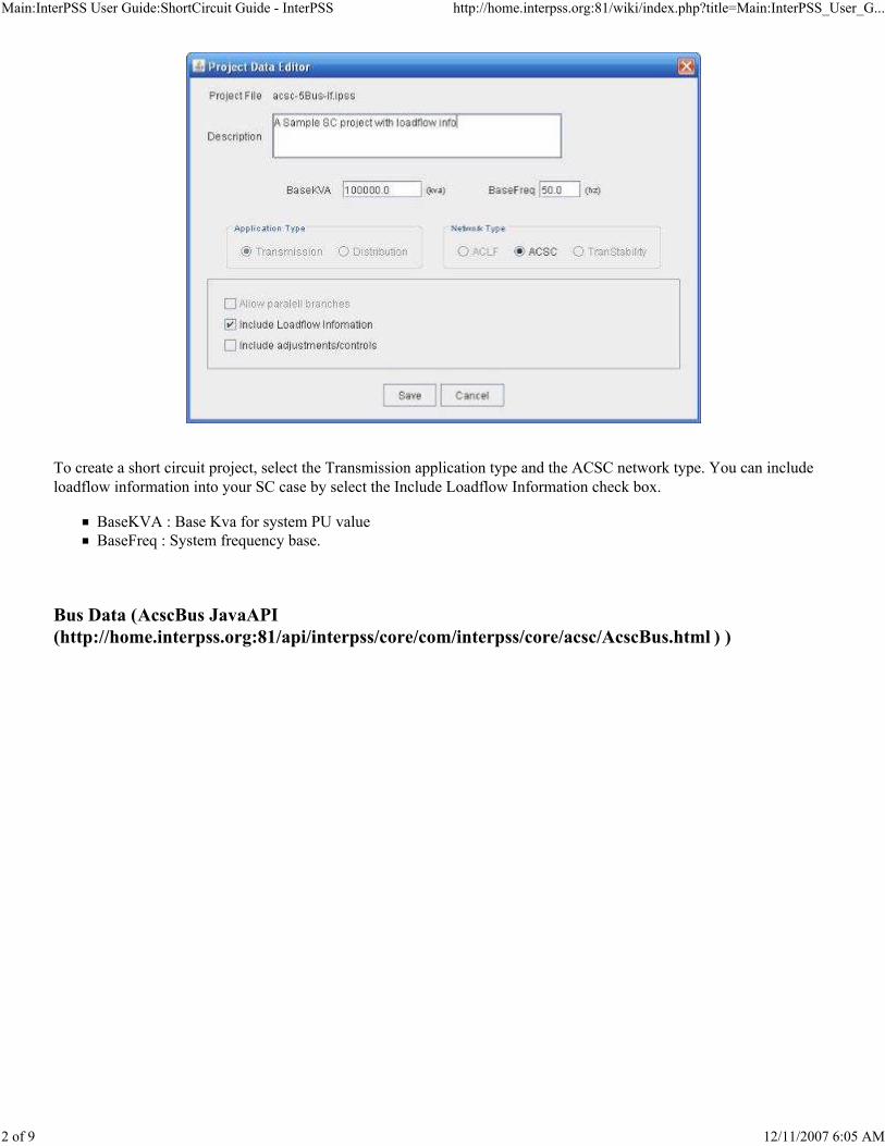
To create a short circuit project, select the Transmission application type and the ACSC network type. You can include
loadflow information into your SC case by select the Include Loadflow Information check box.
BaseKVA : Base Kva for system PU value
BaseFreq : System frequency base.
Bus Data (AcscBus JavaAPI
(http://home.interpss.org:81/api/interpss/core/com/interpss/core/acsc/AcscBus.html ) )

Main:InterPSS User Guide:ShortCircuit Guide - InterPSS http://home.interpss.org:81/wiki/index.php?title=Main:InterPSS_User_G...
3 of 9 12/11/2007 6:05 AM
Contribute Bus Type
R(1)/R(2)/R(0)(pu):Internal bus resistance (1/2/0 sequence)X(1)/X(2)/X(0)(pu):Internal bus reactance (1/2/0 sequence)SolidGrounded:Solid grounded busZ-Grounded:Grounded through an impedance Z (GroundR + jGroundX)
UnGrounded:Not groundedNonContribute Bus Type - Not input data needed.
If Loadflow information included in the project, the Loadflow tap would be enabled to allow you to enter loadflow data
for the bus. Scripting - Allow you to write custom Java code to define a Bus for short circuit analysis, see How to Script
InterPSS Bus/Branch Object for details.
Branch Data (AcscBranch JavaAPI
(http://home.interpss.org:81/api/interpss/core/com/interpss/core/acsc/AcscBranch.html ) )
Line Branch

Main:InterPSS User Guide:ShortCircuit Guide - InterPSS http://home.interpss.org:81/wiki/index.php?title=Main:InterPSS_User_G...
4 of 9 12/11/2007 6:05 AM
R1/R0(pu):Line resistance (1/0 sequence). InterPSS assume R(2) = R(1) for line branch.
X1/X0(pu):Line reactance (1/0 sequence). InterPSS assume X(2) = X(1) for line branch.
1/2B1/B0(pu):Half Line admittance (1/0 sequence). InterPSS assumes B(2) = B(1) for line branch.
Transformer Branch

Main:InterPSS User Guide:ShortCircuit Guide - InterPSS http://home.interpss.org:81/wiki/index.php?title=Main:InterPSS_User_G...
5 of 9 12/11/2007 6:05 AM
In additional to R and X, the following extra date needs to be defined for a transformer branch:
From/To TurnRatio(pu):From-side and to-side transformer turn ratio.
FromSide/ToSide Grounding:Allow you to define From-Side and To-Side transformer winding connection.
Delta Connection:△-connection
Wye Connection:Y-connection. For Y-connection, grounding type and optional grounding Z need to bedefined.
Phase-Shift Transformer Branch
Phase-shift transformer needs the same input data as transformer. In addition, a phase-shift angle (at From-side) needs to
be defined. For positive sequence From-side voltage angle will be shifted by the angle value. For negative sequence, the
voltage will be shifted by the angle value. For zero sequence, there is no angle shifting.
The Scripting branch type - Allow you to custom Java code to define a Branch for short circuit analysis, see How to
Script InterPSS Bus/Branch Object for details.

Main:InterPSS User Guide:ShortCircuit Guide - InterPSS http://home.interpss.org:81/wiki/index.php?title=Main:InterPSS_User_G...
6 of 9 12/11/2007 6:05 AM
Run Short Circuit Calculation
After completing data entry of a short circuit project, you can click the SC Analysis menu item to run short circuit
analysis.
For bus fault, select a bus and Bus Fault type
3P:Three phase to ground faultL-G:Single phase to ground faultL-L:Line to line faultLL-G:Line to line to ground faultL-G(r+jx):Line to ground fault impedance, applicable to 3P, L-G and LL-G
L-L(r+jx):Fault impedance between lines, applicable to L-L
Loadflow Prefault Voltage:Use loadflow voltage as prefault voltageFixed Prefault Voltage:Fixed prefault voltage (1.0 pu). You can use the MFactor(%) to increase/decrease fault
current contribution

Main:InterPSS User Guide:ShortCircuit Guide - InterPSS http://home.interpss.org:81/wiki/index.php?title=Main:InterPSS_User_G...
7 of 9 12/11/2007 6:05 AM
MFactor(%): A multiplying factor can be defined increase/decrease fault current contribution
Please note: You only need to define positive sequence data for 3P fault calculation. For L-G, L-L, or LL-G, you need to
enter negative and zero sequence data.
For branch fault, select a branch and Branch Fault type. In addition to data defined in the bus fault section,
Fault Distance :Define fault distance in % from the From-Bus.
Short Circuit Output

Main:InterPSS User Guide:ShortCircuit Guide - InterPSS http://home.interpss.org:81/wiki/index.php?title=Main:InterPSS_User_G...
8 of 9 12/11/2007 6:05 AM
After a successful SC analysis run, analysis results will be displayed.
Main:InterPSS User Guide:ShortCircuit Guide - InterPSS http://home.interpss.org:81/wiki/index.php?title=Main:InterPSS_User_G...
9 of 9 12/11/2007 6:05 AM
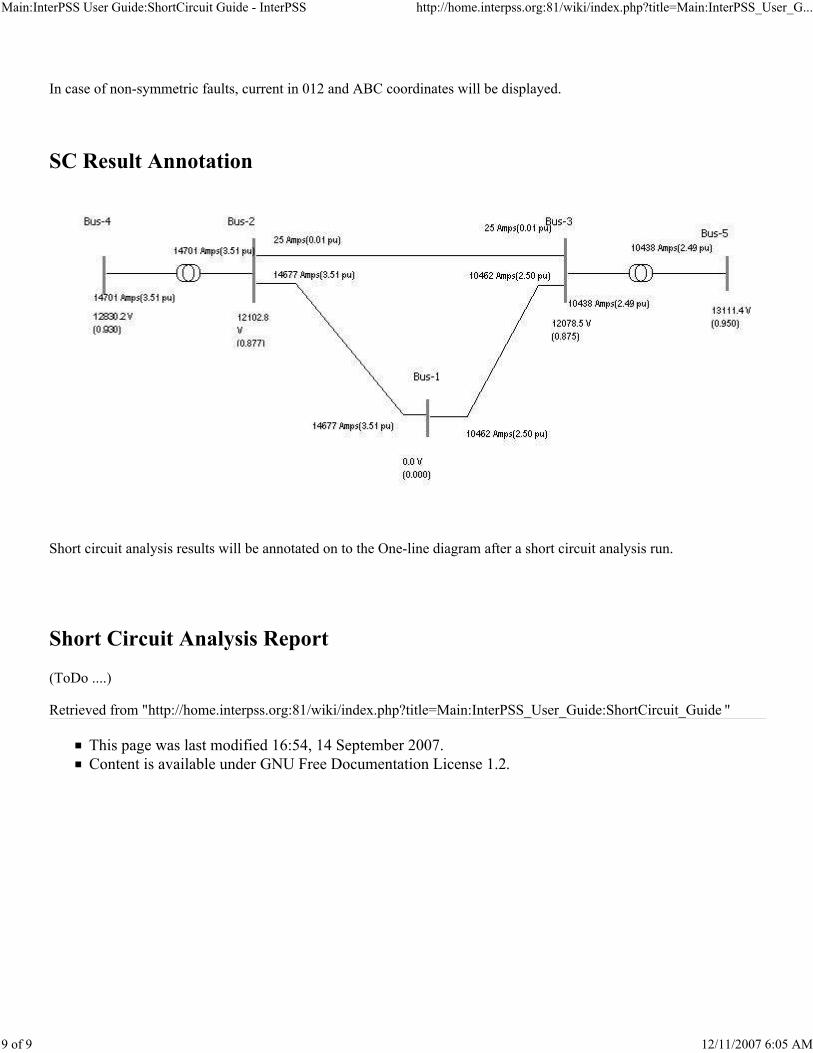
In case of non-symmetric faults, current in 012 and ABC coordinates will be displayed.
SC Result Annotation
Short circuit analysis results will be annotated on to the One-line diagram after a short circuit analysis run.
Short Circuit Analysis Report
(ToDo ....)
Retrieved from "http://home.interpss.org:81/wiki/index.php?title=Main:InterPSS_User_Guide:ShortCircuit_Guide "
This page was last modified 16:54, 14 September 2007.
Content is available under GNU Free Documentation License 1.2.
Main:InterPSS User Guide: Transient Stability Guide - InterPSS http://home.interpss.org:81/wiki/index.php?title=Main:InterPSS_User_G...
1 of 23 12/11/2007 6:07 AM
Links
InterPSS User Guide
InterPSS Project Overview
InterPSS Installation and Administration Guide
InterPSS Graphic Editor User Guide
InterPSS Loadflow User Guide
InterPSS Short Circuit User Guide
InterPSS Transient Stability User Guide
InterPSS Distribution System User Guide
InterPSS Grid Computing Solution
InterPSS Power Market Solution
Main:InterPSS User Guide: Transient Stability Guide
From InterPSS
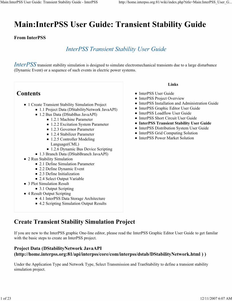
InterPSS Transient Stability User Guide
InterPSS transient stability simulation is designed to simulate electromechanical transients due to a large disturbance(Dynamic Event) or a sequence of such events in electric power systems.
Contents
1 Create Transient Stability Simulation Project
1.1 Project Data (DStabilityNetwork JavaAPI)
1.2 Bus Data (DStabBus JavaAPI)
1.2.1 Machine Parameter
1.2.2 Excitation System Parameter
1.2.3 Governor Parameter
1.2.4 Stabilizer Parameter
1.2.5 Controller Modeling
Language(CML)
1.2.6 Dynamic Bus Device Scripting
1.3 Branch Data (DStabBranch JavaAPI)
2 Run Stability Simulation
2.1 Define Simulation Parameter
2.2 Define Dynamic Event
2.3 Define Initialization
2.4 Select Output Variable
3 Plot Simulation Result
3.1 Output Scripting
4 Result Output Scripting
4.1 InterPSS Data Storage Architecture
4.2 Scripting Simulation Output Results
Create Transient Stability Simulation Project
If you are new to the InterPSS graphic One-line editor, please read the InterPSS Graphic Editor User Guide to get familar
with the basic steps to create an InterPSS project.
Project Data (DStabilityNetwork JavaAPI
(http://home.interpss.org:81/api/interpss/core/com/interpss/dstab/DStabilityNetwork.html ) )
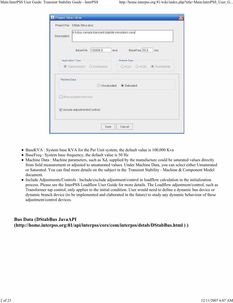
Under the Application Type and Network Type, Select Transmission and TranStability to define a transient stability
simulation project.
Main:InterPSS User Guide: Transient Stability Guide - InterPSS http://home.interpss.org:81/wiki/index.php?title=Main:InterPSS_User_G...
2 of 23 12/11/2007 6:07 AM
BaseKVA : System base KVA for the Per Unit system, the default value is 100,000 Kva
BaseFreq : System base frequency, the default value is 50 Hz
Machine Data : Machine parameters, such as Xd, supplied by the manufacture could be saturated values directly
from field measurement or adjusted to unsaturated values. Under Machine Data, you can select either Unsaturated
or Saturated. You can find more details on the subject in the Transient Stability - Machine & Component Model
document.
Include Adjustments/Controls : Include/exclude adjustment/control in loadflow calculation in the initialization
process. Please see the InterPSS Loadflow User Guide for more details. The Loadflow adjustment/control, such as
Transformer tap control, only applies to the initial condition. User would need to define a dynamic bus device or
dynamic branch device (to be implemented and elaborated in the future) to study any dynamic behaviour of these
adjustment/control devices.
Bus Data (DStabBus JavaAPI
(http://home.interpss.org:81/api/interpss/core/com/interpss/dstab/DStabBus.html ) )

Main:InterPSS User Guide: Transient Stability Guide - InterPSS http://home.interpss.org:81/wiki/index.php?title=Main:InterPSS_User_G...
3 of 23 12/11/2007 6:07 AM
First you need to enter Bus loadflow data for establishing a steady-state as the initial condition for transient stability
simulation. To add a machine dynamic model, you need to select Generator Type = Swing, PQ, PV or RemoteControl. If
you would like to define a custom dynamic model for the bus, select the Dynamic Bus Device Scripting check box (see
more discussion on this subject beblow).
Machine Parameter

Main:InterPSS User Guide: Transient Stability Guide - InterPSS http://home.interpss.org:81/wiki/index.php?title=Main:InterPSS_User_G...
4 of 23 12/11/2007 6:07 AM
After a bus has been defined and Generator Type selected (i.e. Swing, PV, PQ or RemoteControl), you need to determine
the machine model and define machine parameters for Transient Stability Simulation. You can find more details about
InterPSS machine models at InterPSS Reference manual in Transient Stability - Machine & Component Model. To add
machine controllers (Excitation system, governor system, PSS), select the Has Excitation Controller and/or Has Governor
Controller check box; the PSS is enabled by selecting Has Stabilizer in the Exciter Info tab.
Excitation System Parameter

Main:InterPSS User Guide: Transient Stability Guide - InterPSS http://home.interpss.org:81/wiki/index.php?title=Main:InterPSS_User_G...
5 of 23 12/11/2007 6:07 AM
Various types of excitation system models are included in the InterPSS. To define an excitation system, select an
excitation system model in the Type drop down list and enter the necessary parameters. For more detailed information on
InterPSS excitation system implementation, please see InterPSS Reference Manual Transient Stability - Excitation
System. A user can also select the CML Scripting Exciter to define a custom excitation system using InterPSS Controller
Modeling Language (CML) (http://docs.google.com/View?docid=dz384d8_18ckbtn4) . Check the Has Stabilizer box if
you want to add a Power System Stabilizer (PSS).
Governor Parameter
Main:InterPSS User Guide: Transient Stability Guide - InterPSS http://home.interpss.org:81/wiki/index.php?title=Main:InterPSS_User_G...
6 of 23 12/11/2007 6:07 AM
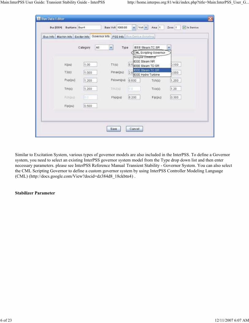
Similar to Excitation System, various types of governor models are also included in the InterPSS. To define a Governor
system, you need to select an existing InterPSS governor system model from the Type drop down list and then enter
necessary parameters. please see InterPSS Reference Manual Transient Stability - Governor System. You can also select
the CML Scripting Governor to define a custom governor system by using InterPSS Controller Modeling Language
(CML) (http://docs.google.com/View?docid=dz384d8_18ckbtn4) .
Stabilizer Parameter
Main:InterPSS User Guide: Transient Stability Guide - InterPSS http://home.interpss.org:81/wiki/index.php?title=Main:InterPSS_User_G...
7 of 23 12/11/2007 6:07 AM
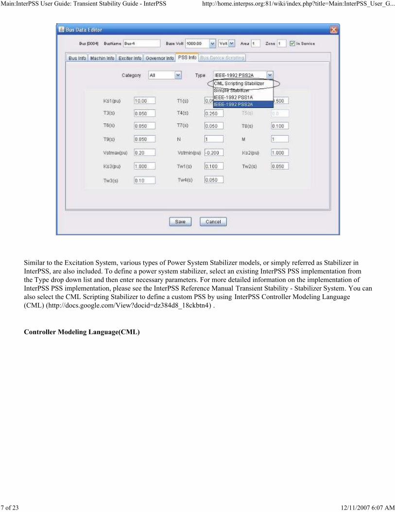
Similar to the Excitation System, various types of Power System Stabilizer models, or simply referred as Stabilizer in
InterPSS, are also included. To define a power system stabilizer, select an existing InterPSS PSS implementation from
the Type drop down list and then enter necessary parameters. For more detailed information on the implementation of
InterPSS PSS implementation, please see the InterPSS Reference Manual Transient Stability - Stabilizer System. You can
also select the CML Scripting Stabilizer to define a custom PSS by using InterPSS Controller Modeling Language
(CML) (http://docs.google.com/View?docid=dz384d8_18ckbtn4) .
Controller Modeling Language(CML)

Main:InterPSS User Guide: Transient Stability Guide - InterPSS http://home.interpss.org:81/wiki/index.php?title=Main:InterPSS_User_G...
8 of 23 12/11/2007 6:07 AM
When you select CML controller type, for example CML Scripting Exciter, you will be presented with an editor dialog
box with some sample code. You can define your own custom controller model by writing CML scripts. After completing
the editing, click the Save button to save your scripts. At this time, InterPSS will compile your scripts. If there is any
error, you will be presented with error messages, as shown in the following diagram.

Main:InterPSS User Guide: Transient Stability Guide - InterPSS http://home.interpss.org:81/wiki/index.php?title=Main:InterPSS_User_G...
9 of 23 12/11/2007 6:07 AM
InterPSS Controller Modeling Language is designed to simplify controller modeling for transient stability simulation.
One can write CML scripts to define a custom controller, including Exciter, Governor and Stabilizer. You can find more
info about CML at the following links:
InterPSS Controller Modeling Language (CML) (http://docs.google.com/View?docid=dz384d8_18ckbtn4)
CML Tutorial (http://docs.google.com/Doc?id=dd7m5rrq_77c84vq6)
CML Controller Implementation Example Static Exciter
(http://docs.google.com/Doc?docid=dd7m5rrq_151dt52b2&hl=en_US)
Dynamic Bus Device Scripting

Main:InterPSS User Guide: Transient Stability Guide - InterPSS http://home.interpss.org:81/wiki/index.php?title=Main:InterPSS_User_G...
10 of 23 12/11/2007 6:07 AM
If the standard InterPSS machine and controller models do not meet your simulation requirement, you can create a
custom bus simulation mode by using Dynamic Bus Device scripting. In this approach, you can define a dynamic source
or load, where source/load injection current into the network is a function of bus voltage and time
The function could be a set of differential and/or static equations. Dynamic Bus Device gives you a generic way to script
such a function. It could be used to model dynamic load including motors, SVC, FACTS or complex generation station
dynamics. For more details, see InterPSS Extension Guide - How to Script Dynamic Bus Device .
Branch Data (DStabBranch JavaAPI
(http://home.interpss.org:81/api/interpss/core/com/interpss/dstab/DStabBranch.html ) )
Branch data required for transient stability simulation is the same as the Short Circuit analysis.
Branch data is prepared the same way as preparing branch data for Loadflow analysis and Short Circuit analysis.
I = f(V, t)

Main:InterPSS User Guide: Transient Stability Guide - InterPSS http://home.interpss.org:81/wiki/index.php?title=Main:InterPSS_User_G...
11 of 23 12/11/2007 6:07 AM
Run Stability Simulation
After completing data entry of a transient stability simulation project, you can run simulation by select the Run/Transient
Stability menu item or the Run TS button. The simulation progress bar will show the progress of a simulation run with a
percentage Run DStab (14%).
Define Simulation Parameter

Main:InterPSS User Guide: Transient Stability Guide - InterPSS http://home.interpss.org:81/wiki/index.php?title=Main:InterPSS_User_G...
12 of 23 12/11/2007 6:07 AM
Simulation Method : Solution method for dynamic differential equation. Currently, only Modified Euler method is
available. More choices will be available in the future.
Disable Dynamic Events : Transient stability simulation always starts from a steady-state condition. At t = 0.0,
InterPSS goes through an initialization process. It is possible that a steady-state condition cannot be established
because of entry error or incorrectly operating condition specification. By select this option, InterPSS will run the
simulation by disabling all event. Normally you should see response curve of all state variable as straight lines.
This function is designed to allow you to investigate situations where initial steady-state condition might be
specified incorrectly.
Total Time(sec) : Total simulation time in sec.
Simu Step(sec) : Simulation time step. The step applies to all dynamic devices in the system. We recommend a
simulation time step of 1/5 of the smallest time constant in the system.
Ref Machine : InterPSS allows to you to output machine angle relative or absolute value. When you choose
relative value, you need to select a reference machine. InterPSS will recommend the machine with the largest
inertia as the reference machine.
Absolute Machine Angle : Option for absolute or relative angle
Net Eqn Iterations (No Event) : InterPSS uses iterative method to solve the network equation because of generator
injection current is a non-linear function of generator bus voltage. You can specify a number for the iteration when

Main:InterPSS User Guide: Transient Stability Guide - InterPSS http://home.interpss.org:81/wiki/index.php?title=Main:InterPSS_User_G...
13 of 23 12/11/2007 6:07 AM
there is no dynamic event at the simulation step.
Net Eqn Iterations (With Event) : You can specify a number for the iteration when there is a dynamic event(s) at
the simulation step. Normally you should give a large number than the No Event number, since with dynamic
event, more iterations are needed to achieve the same accuracy.
Output state/variable Filter : Option for you to select a sub-set of state/variable to be output. See below for more
details.
Output Result Scripting : Option for you to performance Output Result Scripting. See below for more details.
Static Load Model : You can model static load either as an impedance or a constant power source.
SwitchVolt(pu) : When using constant power load model, the load will be switched to constant impedance
load when the bus voltage becomes lower than a switch voltage threshhold, SwitchVolt(pu). It will be
switched back to constant power load model when the voltage becomes higher than the threshhold plus the
Dead Zone to avoid constant switching.
DeadZone(pu) : Dead zone for load simulation model switching
Controller SetPoint Change : Some time you might want make a step change to the set point or reference point of a
controller to verify if parameters of the controller have been entered correctly. When you select the Disable
Dynamic Events checkbox, the Controller SetPoint Change area will be enabled to allow you to define a controller
set point change event.
Machine : Select a machine where you want to make set point change
Controller : List of all controllers on the selected machine
SetPoint Value Change : Set point/reference point change value
Absulte or Delta : Specify if the change is absolute or delta - a change to the steady-state value, which is
calculated during the initialization process.
Define Dynamic Event

Main:InterPSS User Guide: Transient Stability Guide - InterPSS http://home.interpss.org:81/wiki/index.php?title=Main:InterPSS_User_G...
14 of 23 12/11/2007 6:07 AM
Dynamic Event List : Dynamic event list. You can have multiple dynamic events defined with the limitation that
you cannot have two simultaneous un-symmetric faults presented in the system at the same time.
Dynamic Event Type : Currently four types of dynamic events are implemented. For details see the Transient
Stability - Dynamic Events reference document.
Start Time(sec): Event start time
Duration(sec) : Event duration, if not a permanent event
Permanent : For permanent event, it will last the total during of the simulation duration
Dynamic Event Details : different type of events have different input screen for event data. For example, for Bus
Fault Event, enter the following data:
Fault Bus : select fault bus
3P:Three phase to ground faultL-G:Single phase to ground faultL-L:Line to line faultLL-G:Line to line and ground faultL-G(r+jx):Line to ground fault impedance, applicable to 3P, L-G and LL-GL-L(r+jx):Fault impedance between lines, applicable to L-L
AddEvent : Add a new dynamic event

Main:InterPSS User Guide: Transient Stability Guide - InterPSS http://home.interpss.org:81/wiki/index.php?title=Main:InterPSS_User_G...
15 of 23 12/11/2007 6:07 AM
SaveEvent : Save the current dynamic event
DeleteEvent : Delete the current dynamic event
For details on all types of Dynamic Event, see the Transient Stability - Dynamic Events reference document.
Define Initialization
InterPSS uses loadflow module to establish a steady-state condition for transient stability simulation. This panel allows
you to define initialization related parameters, which are the same as InterPSS loadflow analysis. See InterPSS Loadflow
User Guide for details.
Select Output Variable

Main:InterPSS User Guide: Transient Stability Guide - InterPSS http://home.interpss.org:81/wiki/index.php?title=Main:InterPSS_User_G...
16 of 23 12/11/2007 6:07 AM
InterPSS by default outputs all simulation states and variable to its internal database for simulation result display/output
purpose. This however will sometime slow down the simulation, since it takes time to write the result to the database,
especially for a large size system. When you select the Output state/variable Filter option on the Simulation panel, you
have the choice to select a set of states and/or variables to be included in the output list. In this way, you can speed up the
simulation process by saving less data into the database. When you select a machine, the output includes all machine
states and its controller states, including Excitation system, Governor, PSS.
In the above case, machine states of machine on Bus 0004 and bus variables at Bus 0001 will be output to the database,
and available to display after the simulation.
Plot Simulation Result

Main:InterPSS User Guide: Transient Stability Guide - InterPSS http://home.interpss.org:81/wiki/index.php?title=Main:InterPSS_User_G...
17 of 23 12/11/2007 6:07 AM
After completing a simulation, right-click a bus, you can have choice to plot any state variable associated with the bus.
You can also select Output->Plot Stability Curve to launch the Simulation Plotting Dialog.

Main:InterPSS User Guide: Transient Stability Guide - InterPSS http://home.interpss.org:81/wiki/index.php?title=Main:InterPSS_User_G...
18 of 23 12/11/2007 6:07 AM
The "P" button allows you to plot a selected state/variable. The "S" allows you to produce scripted output. See the
following section for details.
Output Scripting
You can write scripts to output a set of variables in certain format. You can click the Scripting tab and write your scripts.
Then click the S button to run your scripts.

Main:InterPSS User Guide: Transient Stability Guide - InterPSS http://home.interpss.org:81/wiki/index.php?title=Main:InterPSS_User_G...
19 of 23 12/11/2007 6:07 AM
The following are sample code for scripting the output,
public class OutDStabResult2TextDialog extends ScriptToolAdapter { public void outDStabResult2TextDialog( IOutputTextDialog textDialog, // out text dialog List<String> nameList, // variable name list List<Hashtable<String, String>> valueList // var value list ) { // clear the text area textDialog.clearTextArea(); /* do not modify anything above this line */ // create a comma delimited names (Time, Machine Angle ... String nameLine = ""; int cnt = 0; for ( String str : nameList) { nameLine += str; if ( cnt++ < nameList.size()-1) nameLine += ", "; } textDialog.appendText(nameLine + "\n"); // create comma delimited value lines for ( Hashtable<String, String> table : valueList) { String valueLine = ""; for ( int j = 0; j < nameList.size(); j++) { String name = nameList.get(j); valueLine += table.get(name); if ( j < nameList.size()-1) valueLine += ", "; } textDialog.appendText(valueLine + "\n"); } /* do not modify anything below this line */ // show the text dialog box textDialog.showDialog(); } }

Main:InterPSS User Guide: Transient Stability Guide - InterPSS http://home.interpss.org:81/wiki/index.php?title=Main:InterPSS_User_G...
20 of 23 12/11/2007 6:07 AM
Then you can save the output to a file by clicking the SaveAs button.
Result Output Scripting
Transient stability simulation results are time domain points. They are normally plotted as plots. InterPSS currently
provides a plot routine which allows you to plot machine states, bus variables and dynamic bus device states. Although
the plot routine provides a quite convenient way to display the results, you may want to do customization or use some
existing tools, such as Microsoft Excel, to do the plotting. You can use InterPSS scripting to export the data points to a
CSV file and then use any tool to customize the plotting.
InterPSS Data Storage Architecture

Main:InterPSS User Guide: Transient Stability Guide - InterPSS http://home.interpss.org:81/wiki/index.php?title=Main:InterPSS_User_G...
21 of 23 12/11/2007 6:07 AM
InterPSS simulation engine sends simulation result out as messages. It does not know who listens and processes
the message. InterPSS has two output message categories: Simulation Step Message and Plot Step Message.
Simulation Step Messages are sent out at each simulation step, while Plot Step Messages are sent out at plotting
steps, which may be different than the simulation steps. InterPSS adjusts the plot step such that the total plotting
points are approximate 500 points.
User can define a filter to filter out the messages. For example, you may be only interested in machines in certain
area/zone or belong to certain owner.
You can plugin output message handler(s) to process the message. Currently, the default result output message
handler is a database result handler, which listens to the messages and store them into InterPSS internal database.
After the simulation, one can use the Database access module to access the stored results and use the InterPSS Plot
Routine to plot simulation curves. The plot routine also is a plugin. One can replace it with a custom
implementation.
Scripting Simulation Output Results
When you run a Transient Stability simulation case, you can check the Output Results Scripting option to write custom
scripts to customize the simulation result output to a file in CVS format.
Main:InterPSS User Guide: Transient Stability Guide - InterPSS http://home.interpss.org:81/wiki/index.php?title=Main:InterPSS_User_G...
22 of 23 12/11/2007 6:07 AM
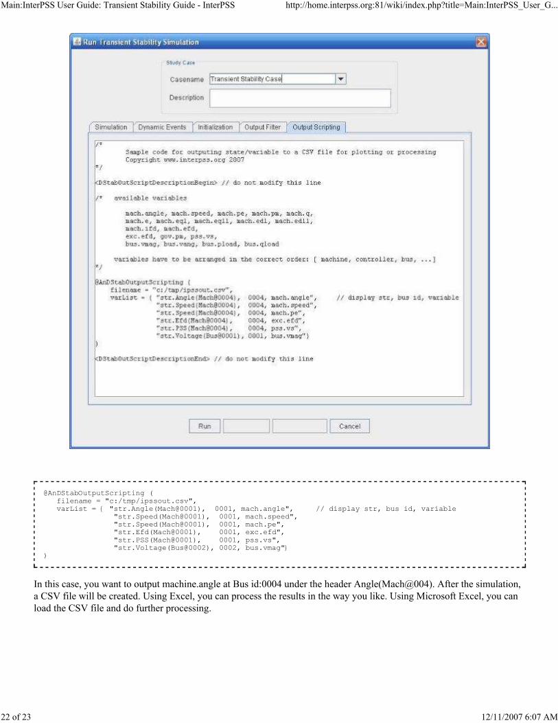
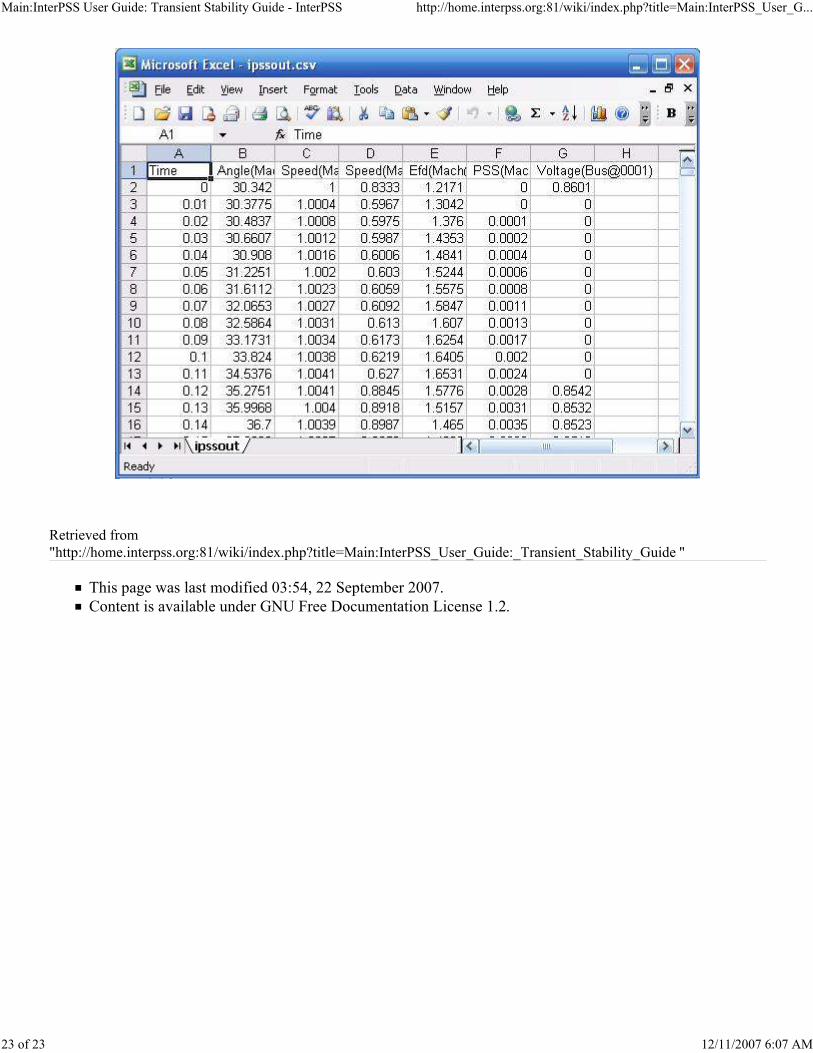
In this case, you want to output machine.angle at Bus id:0004 under the header Angle(Mach@004). After the simulation,
a CSV file will be created. Using Excel, you can process the results in the way you like. Using Microsoft Excel, you can
load the CSV file and do further processing.
@AnDStabOutputScripting ( filename = "c:/tmp/ipssout.csv", varList = { "str.Angle(Mach@0001), 0001, mach.angle", // display str, bus id, variable "str.Speed(Mach@0001), 0001, mach.speed", "str.Speed(Mach@0001), 0001, mach.pe", "str.Efd(Mach@0001), 0001, exc.efd", "str.PSS(Mach@0001), 0001, pss.vs", "str.Voltage(Bus@0002), 0002, bus.vmag"} )
Main:InterPSS User Guide: Transient Stability Guide - InterPSS http://home.interpss.org:81/wiki/index.php?title=Main:InterPSS_User_G...
23 of 23 12/11/2007 6:07 AM
Retrieved from
"http://home.interpss.org:81/wiki/index.php?title=Main:InterPSS_User_Guide:_Transient_Stability_Guide "
This page was last modified 03:54, 22 September 2007.
Content is available under GNU Free Documentation License 1.2.
Main:InterPSS User Guide: Distribution System - InterPSS http://home.interpss.org:81/wiki/index.php?title=Main:InterPSS_User_G...
1 of 22 12/11/2007 6:09 AM
Links
InterPSS User Guide
InterPSS Project Overview
InterPSS Installation and Administration Guide
InterPSS Graphic Editor User Guide
InterPSS Loadflow User Guide
InterPSS Short Circuit User Guide
InterPSS Transient Stability User Guide
InterPSS Distribution System User Guide
InterPSS Grid Computing Solution
InterPSS Power Market Solution
Main:InterPSS User Guide: Distribution System
From InterPSS
InterPSS Distribution System User Guide
InterPSS divides power system simulation into two main categories: 1) Transmission system analysis and 2)
Distribution system analysis. InterPSS distribution system analysis module is design for medium and low voltage power
distribution system analysis. In the distribution system analysis, power system equipments, such as generator and motor,
are described using nameplate values, such as Ohms, or HousePower. InterPSS distribution system analysis shares the
same underlying power system simulation framework and core simulation engine with InterPSS transmission system
analysis.
Contents
1 Introduction
1.1 Distribution System Representation
1.2 Loadflow Analysis
1.3 Short Circuit (SC) Calculation
1.4 SC Standard and Multi-Point SC Calculation
1.5 Voltage Profile Analysis
2 Create Distribution System Project
2.1 Project Data (DistNetwork JavaAPI)
2.1.1 ANSI Standard
2.2 Bus Data (DistBus JavaAPI)
2.2.1 Utility Bus
2.2.2 Generator Bus
2.2.3 SynMotor Bus
2.2.4 IndMotor Bus
2.2.5 MixedLoad Bus
2.2.6 NonContribute Bus
2.3 Branch Data (DistBranch JavaAPI)
2.3.1 Feeder Branch
2.3.2 Breaker Branch
2.3.3 Transformer Branch
3 Run Distribution System Analysis
3.1 Run Loadflow Analysis
3.1.1 Load Profile Analysis
3.2 Run Short Circuit Analysis
3.2.1 Run ANSI Multi-Point SC
4 Loadflow and SC Report
4.1 Loadflow Report
4.2 SC Report
5 Sample Distribution System Project

Main:InterPSS User Guide: Distribution System - InterPSS http://home.interpss.org:81/wiki/index.php?title=Main:InterPSS_User_G...
2 of 22 12/11/2007 6:09 AM
Introduction
In InterPSS distribution system analysis, power system equipments, such as generator and motor, are described using
nameplate values, such as Ohms, or HousePower. It is design for medium and low voltage power distribution system
analysis.
Distribution System Representation
Currently InterPSS distribution system analysis can by used to model the following bus equipments:
Utility Bus - For representing interface to utility company. Normally, there is only one such interface in a
distribution system. InterPSS, however, allows you to have multiple such interfaces defined in your project. In such
a case, you have to make sure that the Utility bus voltage angles are specified correctly.
Generator Bus - For representing generators for distribution system loadflow and short circuit analysis.
Synchronous Motor Bus - For representing synchronous motor for distribution system loadflow and short circuit
analysis
Induction Motor Bus - For representing induction motor for distribution system loadflow and short circuit analysis
Mixed Load Bus - For representing mixed static KVA load and motor load for distribution system loadflow and
short circuit analysis
NonContribute - For representing a non-contributing bus
Currently InterPSS distribution system analysis could be used to model the following branch devices:
Feeder Branch - For representing feeder, including cable for distribution system loadflow and short circuit analysis
Transformer Branch - For representing 2-winding transformer for distribution system loadflow and short circuit
analysis
Breaker Branch - For representing circuit breaker for distribution system loadflow and short circuit analysis
Loadflow Analysis
After you build an InterPSS distribution system project, you have defined enough information for loadflow analysis. By
running loadflow analysis, you can find bus voltage, voltage dip, branch KW/Kvar flow and branch current flow.
Short Circuit (SC) Calculation
After you build an InterPSS distribution system project, you have defined enough information for short circuit
calculation. By running Short Circuit calculation, you can calculate short circuit current, when there is a bus fault or a
branch fault. You can select any fault location and apply 3-Phase, Line-Ground, Line-Line or Line-Line-Ground fault.
SC Standard and Multi-Point SC Calculation
One of the main purposes of short circuit calculation is for equipment selection and protective device coordination.
Normally one would calculate short circuit current value at the following three points:
Momentary Peak Value at half-cycle for validating equipment withstand
Interrupting Value at 3-5 cycle to make sure the breaker will operate correctly
Steady-state value, 20-cycle and beyond to make that concerned equipment will not be overheated or for fuse
selection.
Different countries and different manufactures have different standards. However, you always need to perform multiple
short circuit calculations. You can then use the calculation results to find out X/R ratio and to determine the DC
component for protective device coordination. InterPSS allows you to perform up to 5 point short circuit calculation.
Future version will allow advanced user to plugin their own standard.

Main:InterPSS User Guide: Distribution System - InterPSS http://home.interpss.org:81/wiki/index.php?title=Main:InterPSS_User_G...
3 of 22 12/11/2007 6:09 AM
Voltage Profile Analysis
Load and generation, in distribution systems, change with time. You may want to define load profile, a set of load points,
and/or generation profile, to study how bus voltage varies with load change. You can also define service profiles for
transformers to switch on/off to study the effect of such switching on system loss to optimize reactive power flow.
Create Distribution System Project
If you are new to the InterPSS graphic One-line editor, please read the InterPSS Graphic Editor User Guide to get familar
with the basic steps to create an InterPSS project.
Project Data (DistNetwork JavaAPI
(http://home.interpss.org:81/api/interpss/core/com/interpss/dist/DistNetwork.html ) )
To define a Distribution system project, select Distribution application type. The Network Type is always ACSC, which
means you can perform Loadflow and Short Circuit analysis.
Description:Description for the project.BaseKVA:Base Kva for the Per Unit system for the project.
BaseFreq:Base Frequency in Hz for the project.Load Schedule Analysis : Allows to define a set of load schedule points for voltage profile analysis.
Load Points : number of load schedule points
Period Length : load period length
SC Standard : Currently InterPSS support Generic and ANSI
ANSI Standard
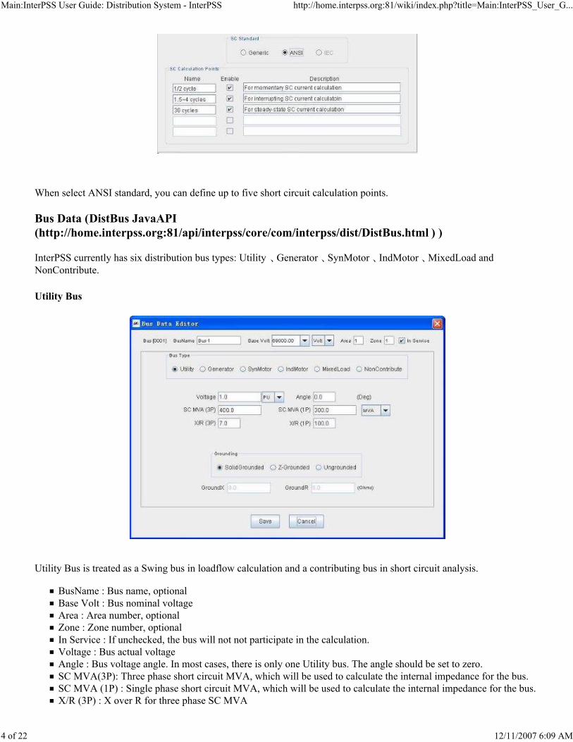
Main:InterPSS User Guide: Distribution System - InterPSS http://home.interpss.org:81/wiki/index.php?title=Main:InterPSS_User_G...
4 of 22 12/11/2007 6:09 AM
When select ANSI standard, you can define up to five short circuit calculation points.
Bus Data (DistBus JavaAPI
(http://home.interpss.org:81/api/interpss/core/com/interpss/dist/DistBus.html ) )
InterPSS currently has six distribution bus types: Utility 、Generator 、SynMotor 、IndMotor 、MixedLoad and
NonContribute.
Utility Bus
Utility Bus is treated as a Swing bus in loadflow calculation and a contributing bus in short circuit analysis.
BusName : Bus name, optional
Base Volt : Bus nominal voltage
Area : Area number, optional
Zone : Zone number, optional
In Service : If unchecked, the bus will not not participate in the calculation.
Voltage : Bus actual voltage
Angle : Bus voltage angle. In most cases, there is only one Utility bus. The angle should be set to zero.
SC MVA(3P): Three phase short circuit MVA, which will be used to calculate the internal impedance for the bus.
SC MVA (1P) : Single phase short circuit MVA, which will be used to calculate the internal impedance for the bus.
X/R (3P) : X over R for three phase SC MVA

Main:InterPSS User Guide: Distribution System - InterPSS http://home.interpss.org:81/wiki/index.php?title=Main:InterPSS_User_G...
5 of 22 12/11/2007 6:09 AM
X/R (1P) : X over R for sinle phase SC MVA
Grounding : For short circuit analysis
SolidGrounded:Solid grounded busZ-Grounded:Grounded through an impedance Z (GroundR + jGroundX)
UnGrounded:Not grounded
The following equations are used to calculate the internal impedance for the Utility Bus:
Generator Bus
Rated KW : Generator equipment rating
Rated V : Generator equipment rated voltage, which may be different than the bus Base/Norminal voltage
PFactor : Generator power factor

Main:InterPSS User Guide: Distribution System - InterPSS http://home.interpss.org:81/wiki/index.php?title=Main:InterPSS_User_G...
6 of 22 12/11/2007 6:09 AM
Loading(%):Generator loading factor, used to calculate the actual generation output = RateKW*Loading/100.
Include Load Schedule : Define generator loading schedule, if the Load Schedule Analysis option has been selected
in the project data panel. You can define a set of P, Q factors to describe a generator P/Q profile.
Short Circuit Impudence : Generator short circuit impedance. In case of ANSI standard, you need to enter Z for
multiple points, as shown in the following diagram.
ZUnit : Generator impedance unit on generator equipment rating and rated voltage base
Grounding : Data entry aame as the Utility Bus
SynMotor Bus
Synchronous Motor bus. Input data is the same as the Induction Motor bus.
IndMotor Bus
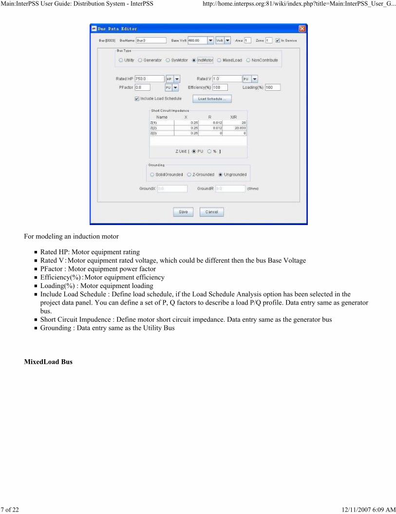
Main:InterPSS User Guide: Distribution System - InterPSS http://home.interpss.org:81/wiki/index.php?title=Main:InterPSS_User_G...
7 of 22 12/11/2007 6:09 AM
For modeling an induction motor
Rated HP: Motor equipment rating
Rated V:Motor equipment rated voltage, which could be different then the bus Base Voltage
PFactor : Motor equipment power factor
Efficiency(%):Motor equipment efficiency
Loading(%) : Motor equipment loading
Include Load Schedule : Define load schedule, if the Load Schedule Analysis option has been selected in the
project data panel. You can define a set of P, Q factors to describe a load P/Q profile. Data entry same as generator
bus.
Short Circuit Impudence : Define motor short circuit impedance. Data entry same as the generator bus
Grounding : Data entry same as the Utility Bus
MixedLoad Bus

Main:InterPSS User Guide: Distribution System - InterPSS http://home.interpss.org:81/wiki/index.php?title=Main:InterPSS_User_G...
8 of 22 12/11/2007 6:09 AM
For representing mixed static load and motor bus
Total KVA : Total bus load rating
Rated V : Bus rated voltage, which could be different then the bus Base Voltage
PFactor:Bus load power factorMotor(%):Motor load percent. It should be always less than 100%. The other part (100%-Motor%) is treated a
static load.
Include Load Schedule Define load schedule, if the Load Schedule Analysis option has been selected in the project
data panel. You can define a set of P, Q factors to describe a load P/Q profile. Data entry same as the generator bus.
Short Circuit Impudence : Define motor short circuit impedance. Data entry same as the generator bus.
Grounding : Data as same as the Utility Bus
NonContribute Bus
NonContribute Bus has no contribution to loadflow analysis and short circuit calculation.
Branch Data (DistBranch JavaAPI
(http://home.interpss.org:81/api/interpss/core/com/interpss/dist/DistBranch.html ) )
Feeder Branch
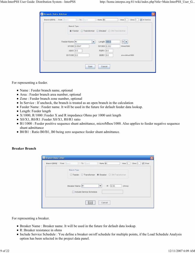
Main:InterPSS User Guide: Distribution System - InterPSS http://home.interpss.org:81/wiki/index.php?title=Main:InterPSS_User_G...
9 of 22 12/11/2007 6:09 AM
For representing a feeder.
Name : Feeder branch name, optional
Area : Feeder branch area number, optional
Zone : Feeder branch zone number, optional
In Service : If uncheck, the branch is treated as an open branch in the calculation
Feeder Name : Feeder name. It will be used in the future for default feeder data lookup.
Length: Feeder length
X/1000, R/1000:Feeder X and R impedance Ohms per 1000 unit length
X0/X1, R0/R1:Feeder X0/X1, R0/R1 ratioB1/1000 : Feeder positive sequence shunt admittance, microMhos/1000. Also applies to feeder negative sequence
shunt admittance
B0/B1 : Ratio B0/B1, B0 being zero sequence feeder shunt admittance.
Breaker Branch
For representing a breaker.
Breaker Name : Breaker name. It will be used in the future for default data lookup.
R:Breaker resistance in ohms
Include Service Schedule : You define a breaker on/off schedule for multiple points, if the Load Schedule Analysis
option has been selected in the project data panel.

Main:InterPSS User Guide: Distribution System - InterPSS http://home.interpss.org:81/wiki/index.php?title=Main:InterPSS_User_G...
10 of 22 12/11/2007 6:09 AM
Transformer Branch
For modeling a transformer branch
Xformer Name: Transformer name, It will be used in the future for default data lookup.
Rating : Transformer KVA rating
Primary/Second Rated V:Primary and secondary rated voltage.
X, R, X/R : Transformer X, R, on the transformer rating and rated voltage base
X0/X1, R0/R1 : Ratio for calculating zero sequence X and R
Primary/Secondary TurnRatio : Transformer primary and secondary turn ratio
Include Service Schedule : You can define a transformer on/off schedule for multiple points, if the Load Schedule
Analysis option is selected in the project data panel.
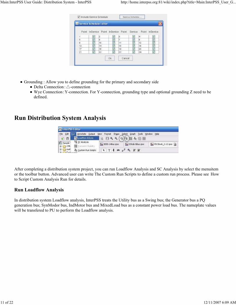
Main:InterPSS User Guide: Distribution System - InterPSS http://home.interpss.org:81/wiki/index.php?title=Main:InterPSS_User_G...
11 of 22 12/11/2007 6:09 AM
Grounding : Allow you to define grounding for the primary and secondary side
Delta Connection:△-connection
Wye Connection:Y-connection. For Y-connection, grounding type and optional grounding Z need to bedefined.
Run Distribution System Analysis
After completing a distribution system project, you can run Loadflow Analysis and SC Analysis by select the menuitem
or the toolbar button. Advanced user can write The Custom Run Scripts to define a custom run process. Please see How
to Script Custom Analysis Run for details.
Run Loadflow Analysis
In distribution system Loadflow analysis, InterPSS treats the Utility bus as a Swing bus; the Generator bus a PQ
generation bus; SynModor bus, IndMotor bus and MixedLoad bus as a constant power load bus. The nameplate values
will be transfered to PU to perform the Loadflow analysis.

Main:InterPSS User Guide: Distribution System - InterPSS http://home.interpss.org:81/wiki/index.php?title=Main:InterPSS_User_G...
12 of 22 12/11/2007 6:09 AM
Select a Loadflow method and enter necessary info, then click Run to run Loadflow analysis. If the Show Loadflow
Summary check box is selected, you will be presented with the Loadflow result summary, as shown in the following
diagram.

Main:InterPSS User Guide: Distribution System - InterPSS http://home.interpss.org:81/wiki/index.php?title=Main:InterPSS_User_G...
13 of 22 12/11/2007 6:09 AM
Select the Bus Style to change the Loadflow output in the IEEE BusStyle format. By click the SaveAs button, you can
save the Loadflow results into a file. Click Close button to close the result disply box. Then the Loadflow results are
annotated onto the One-line diagram, as shown in the following diagram:
Load Profile Analysis

Main:InterPSS User Guide: Distribution System - InterPSS http://home.interpss.org:81/wiki/index.php?title=Main:InterPSS_User_G...
14 of 22 12/11/2007 6:09 AM
When the Load Schedule Analysis option is selected in the project data panel, you can specify multiple Load points at
load buses and/or generation points at generator buses. When you run Loadflod analysis, InterPSS will run multiple
Loadflow for all the points. The following is a sample output of a Load Profile analysis output.
After a Load Profile Analysis run, by clicking a load bus, you can plot its P, Q and voltage profile.

Main:InterPSS User Guide: Distribution System - InterPSS http://home.interpss.org:81/wiki/index.php?title=Main:InterPSS_User_G...
15 of 22 12/11/2007 6:09 AM
Run Short Circuit Analysis
In distribution system SC analysis, InterPSS treats the Utility bus, the Generator bus, the SynModor bus, and the
IndMotor bus as contributing source. Motor load part of the MixedLoad bus is also treated as contributing source. The
nameplate values will be transfered to PU to perform the SC analysis. When you run SC analysis, you will be presented
with the following dialog box:
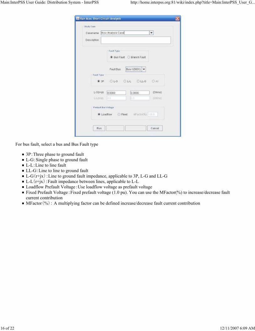
Main:InterPSS User Guide: Distribution System - InterPSS http://home.interpss.org:81/wiki/index.php?title=Main:InterPSS_User_G...
16 of 22 12/11/2007 6:09 AM
For bus fault, select a bus and Bus Fault type
3P:Three phase to ground faultL-G:Single phase to ground faultL-L:Line to line faultLL-G:Line to line to ground faultL-G(r+jx):Line to ground fault impedance, applicable to 3P, L-G and LL-G
L-L(r+jx):Fault impedance between lines, applicable to L-L
Loadflow Prefault Voltage:Use loadflow voltage as prefault voltageFixed Prefault Voltage:Fixed prefault voltage (1.0 pu). You can use the MFactor(%) to increase/decrease fault
current contribution
MFactor(%): A multiplying factor can be defined increase/decrease fault current contribution

Main:InterPSS User Guide: Distribution System - InterPSS http://home.interpss.org:81/wiki/index.php?title=Main:InterPSS_User_G...
17 of 22 12/11/2007 6:09 AM
For branch fault, select a branch and Branch Fault type. In addition to data defined in the bus fault section,
Fault Distance :Define fault distance in % from the From-Bus.
Select the Run button to run SC calculation. After the run, you will be presented with the following result summary
screen:

Main:InterPSS User Guide: Distribution System - InterPSS http://home.interpss.org:81/wiki/index.php?title=Main:InterPSS_User_G...
18 of 22 12/11/2007 6:09 AM
SC results also will be annotated on to the One-line diagram after a SC calculation run.

Main:InterPSS User Guide: Distribution System - InterPSS http://home.interpss.org:81/wiki/index.php?title=Main:InterPSS_User_G...
19 of 22 12/11/2007 6:09 AM
Run ANSI Multi-Point SC
When the ANSI standard is selected in the project data panel, you can define up to five SC points. Different
generator/motor SC impedance could be specified for different SC points to perform multiple-point SC calculation. The
following is a sample output of a Multi-Point SC run.
Loadflow and SC Report
After a successful Loadflow or SC run, you can create Loadflow and SC reports, by selecting the menuitems under the
Output menu or the "R" button.
Loadflow Report
Currently, you can create Loadflow analysis report in two formats: 1) Summary format and 2) the IEEE Bus Style format.
Last reports are saved under the parent project, as shown in the following diagram.

Main:InterPSS User Guide: Distribution System - InterPSS http://home.interpss.org:81/wiki/index.php?title=Main:InterPSS_User_G...
20 of 22 12/11/2007 6:09 AM
A Sample Loadflow Summary Report
A Sample Loadflow IEEE Bus Style Report
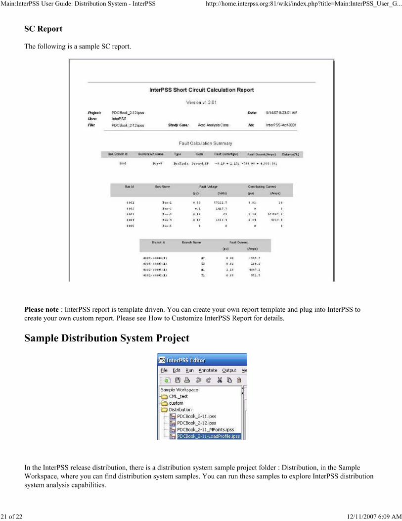
Main:InterPSS User Guide: Distribution System - InterPSS http://home.interpss.org:81/wiki/index.php?title=Main:InterPSS_User_G...
21 of 22 12/11/2007 6:09 AM
SC Report
The following is a sample SC report.
Please note : InterPSS report is template driven. You can create your own report template and plug into InterPSS to
create your own custom report. Please see How to Customize InterPSS Report for details.
Sample Distribution System Project
In the InterPSS release distribution, there is a distribution system sample project folder : Distribution, in the Sample
Workspace, where you can find distribution system samples. You can run these samples to explore InterPSS distribution
system analysis capabilities.

Main:InterPSS User Guide: Distribution System - InterPSS http://home.interpss.org:81/wiki/index.php?title=Main:InterPSS_User_G...
22 of 22 12/11/2007 6:09 AM
PDCBook_2-11.ipss - Sample from Book "Electric Power System Protection and Coordination" by Michael
Anthony, Figure 2.11, page 73
PDCBook_2-12.ipss - Sample from Book "Electric Power System Protection and Coordination" by Michael
Anthony, Figure 2.12, page 75
PDCBook_2-11_MPoints.ipss - Same as PDCBook_2-11, with three SC points
PDCBook_2-11_LoadProfile.ipss - Same as PDCBook_2-11, with 24 load points.
Retrieved from "http://home.interpss.org:81/wiki/index.php?title=Main:InterPSS_User_Guide:_Distribution_System "
This page was last modified 20:39, 14 September 2007.
Content is available under GNU Free Documentation License 1.2.

Main:InterPSS User Guide: Grid Computing Solution - InterPSS http://home.interpss.org:81/wiki/index.php?title=Main:InterPSS_User_G...
1 of 9 12/11/2007 6:09 AM
Links
InterPSS User Guide
InterPSS Project Overview
InterPSS Installation and Administration Guide
InterPSS Graphic Editor User Guide
InterPSS Loadflow User Guide
InterPSS Short Circuit User Guide
InterPSS Transient Stability User Guide
InterPSS Distribution System User Guide
InterPSS Grid Computing Solution
InterPSS Power Market Solution
Main:InterPSS User Guide: Grid Computing Solution
From InterPSS
InterPSS Grid Computing Solution
The goal of InterPSS grid computing solution is to provide a foundation for creating computational grids to perform
computationally-intensive power system simulation using conventional, inexpensive computers in a local area network
(LAN) with minimum administration overhead. We will provide implementation for solving typical power system
simulation problems, such as performing multiple transient stability simulations in parallel on a set of computers. Also,
InterPSS could serve as a foundation for more advanced and/or specific implementations by any interested third party.
Contents
1 Introduction
2 Background Information
2.1 Grid Computing Concept
2.2 Split/Aggregate (Map/Reduce)
2.3 Gridgain
2.4 Terminology
2.5 Computation Job Creation
3 Setup InterPSS Grid Computing Environment
3.1 Install InterPSS
3.2 Configure InterPSS Grid Computing solution
4 Run InterPSS Grid Loadflow
4.1 Start Grid Node
4.2 Start GEditor
4.3 Run Grid Loadflow
4.4 Loadflow Reuslts
5 Run InterPSS Grid Transient Stability Simulation
6 Future Direction
6.1 Source Code
Introduction
Until recently, mainstream understanding of computer simulation is running a computer simulation program, such as a
Loadflow, Transient Stability or Voltage Stability program, or a combination of such programs on a computer. Recent
advance on network technology and software development concept/tools has made it possible to perform "cloud"
computing, where a set of connected computers, forming a computational grid, could be used to solve certain category of
Latest News - The InterPSS development team is currently working on a parallel transient stability simulation approach using InterPSS Grid Computing solution. In a nutshell, one can freely distributes a or a set of transient stability simulation cases to any computation grid node in an InterPSS gird computing environment to perform transient stability simulaiton. The technology will be soon available, as always, as an open-source solution.

Main:InterPSS User Guide: Grid Computing Solution - InterPSS http://home.interpss.org:81/wiki/index.php?title=Main:InterPSS_User_G...
2 of 9 12/11/2007 6:09 AM
computationally intensive problems. "It is no longer enough to program one machine well, to tackle tomorrow's
challenges, we need to be able to program thousands of machines to manage massive amounts of data in the blink of an
eye," by a senior Google software engineer.
InterPSS, from the beginning, has distributed grid computing in mind. InterPSS is completely implemented in Java - a
network ready language. In a nutshell,
InterPSS core simulation engine, implemented in Java current with a size about 1M, could be automatically
distributed over the network and installed/deployed to any gird node without human intervention with minimum
administration overhead.
InterPSS object model, a full object-oriented power system simulation model, could be serialized to an XML
document and distributed over the network to any grid node. Then the XML document could be de-serialized at the
remote grid mode into the original object model and becomes ready for power system simulation.
InterPSS has an open architecture, which allows any interesting party to implement their own grid computing
algorithm on top of InterPSS grid computing foundation to offer customized solution.
Background Information
Grid Computing Concept
Grid computing was started to share unused CUP power over the Internet. However, the concept has been expanded
recently to include high performance distributed parallel computing using a set of connected computers. If we look up
Grid in Wikipedia there's no simple answer, it starts... "Grid computing is a phrase in distributed computing which can
have several meanings". it goes on to describe a number of meanings. While something like SETI@home is technically a
grid implementation, it's not the issue InterPSS grid computing solution is trying to address. Our goal is to create a
software system to perform complex power system simulation in the distributed parallel way. Our targeted environment
is a network of servers in one or a few local subnets with high speed network connection (100Md/s or 1Gb/s). Our
targeted applications include real-time transient stability simulation and power system operation optimization.
Split/Aggregate (Map/Reduce)
The trademark of computational grids is ability to split process into a set of sub-processes, execute them in parallel, and
aggregate sub-results into the one final result. Please note that split can and often does occur recursively. Split and
aggregate (a.k.a Map/Reduce) design allows to parallelize the process of task execution gaining performance and/or
scalability. For example, with simple and inexpensive 10-nodes grid you can achieve "an order of magnitude"
performance increase for your applications, assuming your application is computation intensive and could be split into
independent sub-processes. For more in depth discussion of this concept, please refer to a Google article : MapReduce:
Simplified Data Processing on Large Clusters (http://labs.google.com/papers/mapreduce.html)
Gridgain (http://www.gridgain.com)
GridGain is an open-source computational grid platform. Its goal is to improve general performance of processing
intensive applications by splitting and parallelizing the workload. In many cases GridGain is used to achieve better
overall throughput, better scalability or availability of services. To get a high-level view of the approach, we recommend
watch the 15-min Gridgain introduction screen cast (http://www.gridgain.com/screencast/screencast.html)
InterPSS grid computing solution currently is based on Gridgain. However, the relationship between InterPSS and
Gridgain is loosely coupled, which allows us to relative easily move InterPSS grid computing solution to other grid
computational grid platform in the future, if there is such a need.
Terminology

Main:InterPSS User Guide: Grid Computing Solution - InterPSS http://home.interpss.org:81/wiki/index.php?title=Main:InterPSS_User_G...
3 of 9 12/11/2007 6:09 AM
InterPSS Gird Node - A Gridgain agent instance, running on a physical computer, where compiled InterPSS
simulation code could be deployed from the Master node remotely and automatically through the network to
perform certain simulation job. One or more grid node(s) could be hosted on a physical computer.
InterPSS Master Node - A computer with InterPSS installation. You can also have multiple master nodes in your
computing grid. Also, you can run one or more grid node(s) on a master node.
InterPSS Grid - At least one master node and one or more grid node(s) form an InterPSS computating grid.
InterPSS Grid Job - A unit of simulation work, which could be distributed to any grid node to run independently.
InterPSS Grid Task – Representing a simulation problem, which could be broken into a set of grid jobs and
distributed to grid node(s). A typical grid task consists of many grid jobs. Grid task is responsible to split itself into
grid jobs, distribute them to grid nodes, and aggregate simulation sub-results from grid nodes. Also, grid task
should be implemented in such a way that the compiled implementation code (Java bytecode) could be remotely
deployed to any grid node.
Computation Job Creation
To perform a complex power system simulation, such as evaluating power system transient stability or optimizing system
operation, including unit commitment, for the next day, there is always a need to perform a serious of relatively
independent computation jobs and then consolidate the results of the individual runs to reach a conclusion or decision
(Split/Reduce). Currently InterPSS grid computing solution supports the following two ways to create content of grid
jobs as shown in the following diagram:
Master Node Job Creation - Units of computation work are created by the Master node and distributed to grid
nodes.
Distributed Job Creation - Copies of the MultiStudyCase object are sent to distributed grid nodes to create
computation jobs.
MultiStudyCase (JavaAPI
(http://home.interpss.org:81/api/interpss/core/com/interpss/core/ms_case/MultiStudyCase.html ) ) is a generic InterPSS
concept for multiple study case implementation.
Setup InterPSS Grid Computing Environment
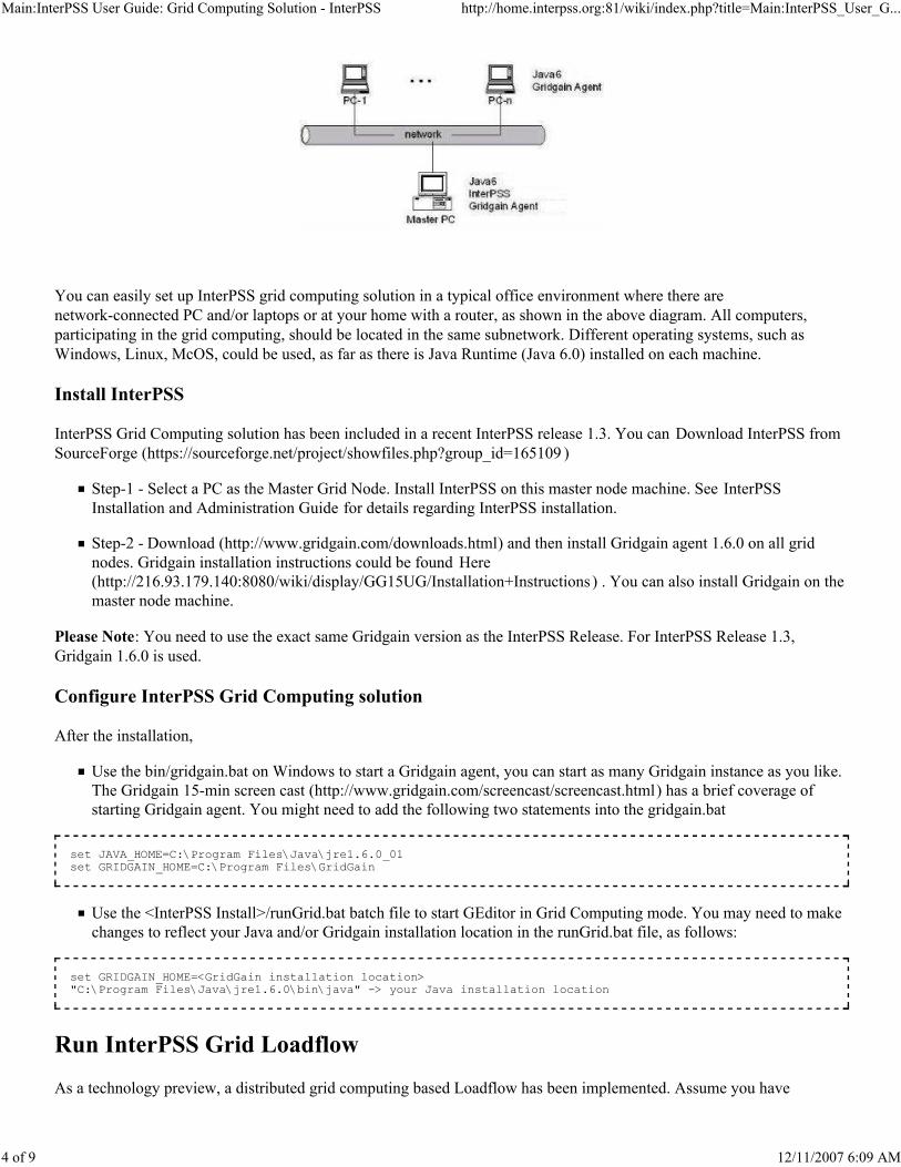
Main:InterPSS User Guide: Grid Computing Solution - InterPSS http://home.interpss.org:81/wiki/index.php?title=Main:InterPSS_User_G...
4 of 9 12/11/2007 6:09 AM
You can easily set up InterPSS grid computing solution in a typical office environment where there are
network-connected PC and/or laptops or at your home with a router, as shown in the above diagram. All computers,
participating in the grid computing, should be located in the same subnetwork. Different operating systems, such as
Windows, Linux, McOS, could be used, as far as there is Java Runtime (Java 6.0) installed on each machine.
Install InterPSS
InterPSS Grid Computing solution has been included in a recent InterPSS release 1.3. You can Download InterPSS from
SourceForge (https://sourceforge.net/project/showfiles.php?group_id=165109 )
Step-1 - Select a PC as the Master Grid Node. Install InterPSS on this master node machine. See InterPSS
Installation and Administration Guide for details regarding InterPSS installation.
Step-2 - Download (http://www.gridgain.com/downloads.html) and then install Gridgain agent 1.6.0 on all grid
nodes. Gridgain installation instructions could be found Here
(http://216.93.179.140:8080/wiki/display/GG15UG/Installation+Instructions ) . You can also install Gridgain on the
master node machine.
Please Note: You need to use the exact same Gridgain version as the InterPSS Release. For InterPSS Release 1.3,
Gridgain 1.6.0 is used.
Configure InterPSS Grid Computing solution
After the installation,
Use the bin/gridgain.bat on Windows to start a Gridgain agent, you can start as many Gridgain instance as you like.
The Gridgain 15-min screen cast (http://www.gridgain.com/screencast/screencast.html) has a brief coverage of
starting Gridgain agent. You might need to add the following two statements into the gridgain.bat
Use the <InterPSS Install>/runGrid.bat batch file to start GEditor in Grid Computing mode. You may need to make
changes to reflect your Java and/or Gridgain installation location in the runGrid.bat file, as follows:
Run InterPSS Grid Loadflow
As a technology preview, a distributed grid computing based Loadflow has been implemented. Assume you have
set JAVA_HOME=C:\Program Files\Java\jre1.6.0_01 set GRIDGAIN_HOME=C:\Program Files\GridGain
set GRIDGAIN_HOME=<GridGain installation location> "C:\Program Files\Java\jre1.6.0\bin\java" -> your Java installation location
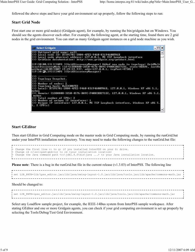
Main:InterPSS User Guide: Grid Computing Solution - InterPSS http://home.interpss.org:81/wiki/index.php?title=Main:InterPSS_User_G...
5 of 9 12/11/2007 6:09 AM
followed the above steps and have your grid environment set up properly, follow the following steps to run:
Start Grid Node
First start one or more grid node(s) (Gridgain agent), for example, by running the bin/gridgain.bat on Windows. You
should see the agents discover each other. For example, the following agent, at the starting time, found there are 2 grid
nodes in the grid environment. You can start as many Gridgain agent instances on a grid node machine as you wish.
Start GEditor
Then start GEditor in Grid Computing mode on the master node in Grid Computing mode, by running the runGrid.bat
under your InterPSS installation root directory. You may need to make the following changes to the runGrid.bat file:
Please note: There is a bug in the runGrid.bat file in the current release (v1.3.03) of InterPSS. The following line
Should be changed to:
Select any Loadflow sample project, for example, the IEEE-14Bus system from InterPSS sample workspace. After
stating GEditor and one or more Gridgain agents, you can check if your grid computing environment is set up properly by
selecting the Tools/Debug/Test Grid Environment.
- Change the first line c: to g: if you installed InterPSS on your G: drive.- Change cd c:\eclipse\geditor to cd <your installation location> - Change the Java command path <c:\jdk1.6.0\bin\java ...> to your Java installation location.
set LIB_PATH=lib/ipss_editor.jar;lib/java/swing-layout-1.0.jar;lib/java/tools.jar;lib/apache/commons-math.jar
set LIB_PATH=ipss_editor.jar;lib/java/swing-layout-1.0.jar;lib/java/tools.jar;lib/apache/commons-math.jar
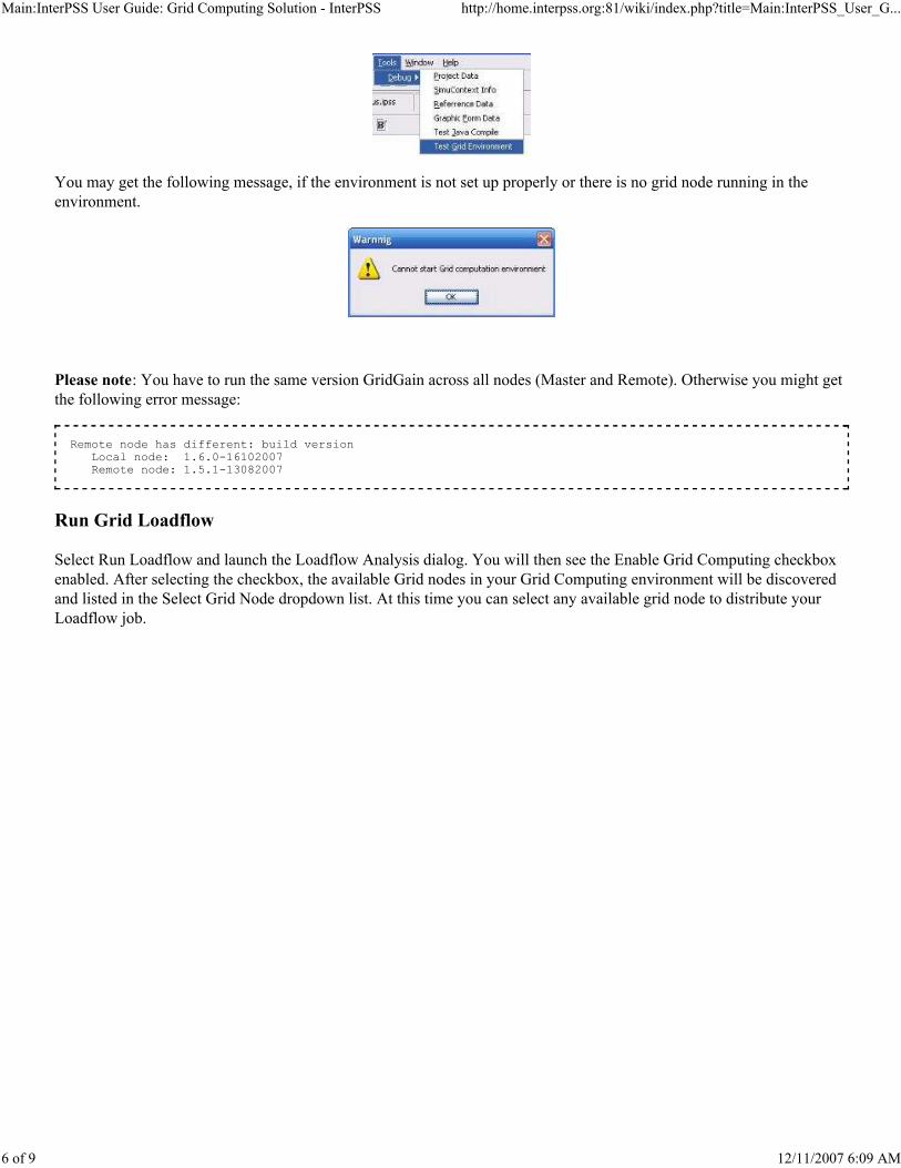
Main:InterPSS User Guide: Grid Computing Solution - InterPSS http://home.interpss.org:81/wiki/index.php?title=Main:InterPSS_User_G...
6 of 9 12/11/2007 6:09 AM
You may get the following message, if the environment is not set up properly or there is no grid node running in the
environment.
Please note: You have to run the same version GridGain across all nodes (Master and Remote). Otherwise you might get
the following error message:
Run Grid Loadflow
Select Run Loadflow and launch the Loadflow Analysis dialog. You will then see the Enable Grid Computing checkbox
enabled. After selecting the checkbox, the available Grid nodes in your Grid Computing environment will be discovered
and listed in the Select Grid Node dropdown list. At this time you can select any available grid node to distribute your
Loadflow job.
Remote node has different: build version Local node: 1.6.0-16102007 Remote node: 1.5.1-13082007

Main:InterPSS User Guide: Grid Computing Solution - InterPSS http://home.interpss.org:81/wiki/index.php?title=Main:InterPSS_User_G...
7 of 9 12/11/2007 6:09 AM
Click the Run button to run InterPSS grid computing. If you are running the grid job on a particular grid node the first
time, after starting the environment, it may take a while to get Loadflow calculation results back. The reason is that the
compiled InterPSS grid task code (Java bytecode) has to be deployed through the network to the grid node. Click the
Refresh button to discover new grid node(s) and refresh the available grid node list.
Please note:
The Enable Grid Computing checkbox is only enabled if your grid environment is set properly and there is at least
one grid node running.
During the installation process, InterPSS is only required to be installed on the master node, not on the other grid
node. When a grid job is distributed to a grid node the first time, the Grid Computing environment discovers that no
code for running the grid job is available on the grid node. It will perform an automatic deployment of InterPSS
grid computing code to the grid node. Then after the first time, if you run another grid job on the grid node again,
the response time will be very fast, since there is no need to do the deployment. No noticeable difference from
running grid job on local machine should be noticed, unless your network is very slow or busy.
InterPSS core engine library could also be installed on all grid nodes and loaded into memory when starting the grid
node. In this way, there won’t be any delay of the response event at the first time, since there is no need to remotely
deploy InterPSS grid code. This way, however, will increase InterPSS grid computing solution administration
overhead.
Loadflow Reuslts

Main:InterPSS User Guide: Grid Computing Solution - InterPSS http://home.interpss.org:81/wiki/index.php?title=Main:InterPSS_User_G...
8 of 9 12/11/2007 6:09 AM
The Loadflow result indicates that the computation was performed at the “Remote Logical Node – 1”. Also, you will see
Loadflow logging information printed out in the remote Gridgain agent output console, as follows:
Run InterPSS Grid Transient Stability Simulation
(Todo ...)
Future Direction
One might ask what is the point to perform a Loadflow calculation on a remote grid node, since running the calculation at
a local machine is much more efficient. InterPSS loadflow calculation consists of multiple power network solution steps

Main:InterPSS User Guide: Grid Computing Solution - InterPSS http://home.interpss.org:81/wiki/index.php?title=Main:InterPSS_User_G...
9 of 9 12/11/2007 6:09 AM
using the sparse technique. This relative simple implementation demonstrated that InterPSS can distribute power network
solution to any remote grid node in a quite easy and efficient way. Power network solution using the sparse technique is
the foundation of all most all power system simulation.
Gartner Group (http://www.gartner.com/it/products/research/research_services.jsp ) thinks that future of computing will
be Computing "fabrics". The fabric based computing environment of the future will treat memory, processors and I/O
cards as components in a pool, combining and recombining them into particular arrangements to suit certain application’s
needs. That is, a large server can be created by combining, for example, 32 processors and a number of memory modules
from the pool, operating together over the fabric to appear to an operating system as a single fixed server. InterPSS Grid
Computing solution is targeted for such computing environments.
This is our first step in attempting to "Gridify" power system simulation. We intend to further develop the technology to
solve more realistic power system simulation problems, such as real-time transient stability assessment. We welcome
interested user to participate in our pursuing of “cloud” computing for power system simulation .
Source Code
(http://interpss.googlecode.com/svn/trunk/ipss.plugin/src/org/interpss/core/grid/gridgain/ )
InterPSS Grid Computing solution implementation source code can be found following the Source Code
(http://interpss.googlecode.com/svn/trunk/ipss.plugin/src/org/interpss/core/grid/gridgain/ ) link. To check out InterPSS
code, please read How to Checkout InterPSS Code .
Retrieved from
"http://home.interpss.org:81/wiki/index.php?title=Main:InterPSS_User_Guide:_Grid_Computing_Solution "
This page was last modified 18:27, 11 December 2007.
Content is available under GNU Free Documentation License 1.2.