interpreting logic float paths in p6
TRANSCRIPT

INTERPRETING LOGIC PATHS IN MULTI-CALENDAR
PROJECT SCHEDULES
Examining Multiple Float Path Calculation in Oracle Primavera P6
Prepared For:
AACE 2020 Annual Meeting
Prepared By:
Thomas M. Boyle, PE, PMP, PSP
(Boyle Project Consulting, PLLC)
and
Patrick M. Kelly, PE PSP
(Ankura Consulting Group, LLC)
25 Mar’20
4236 Chandworth Rd.
Charlotte, NC 28210
Phone: 704-916-6765
Boyle Project Consulting, PLLC
Project Management and Construction Support Services
Interpreting Logic Paths in Multi-Calendar Project Schedules 25 Mar’20
Boyle Project Consulting, PLLC – Charlotte, NC USA i
TABLE OF CONTENTS
1.0 INTRODUCTION .................................................................................................................. 1
2.0 LOGIC PATHS AND DRIVING RELATIONSHIPS ........................................................ 3
3.0 TOTAL FLOAT COMPLICATIONS AND THE LONGEST PATH .............................. 4
4.0 ENHANCED PDM: LOGIC-BASED CODING OF SCHEDULE ACTIVITIES ........... 7
5.0 EPDM IN P6: “CALCULATE MULTIPLE FLOAT PATHS” (MFP) ............................ 8
6.0 MULTIPLE FLOAT PATH CALCULATION ................................................................... 9
7.0 MFP CALCULATION OPTIONS ..................................................................................... 12
8.0 SUMMARY OF MFP EXAMPLES AND INTERPRETATIONS .................................. 15
9.0 OVERALL CONCLUSIONS .............................................................................................. 18
10.0 REFERENCES ................................................................................................................. 20
11.0 APPENDIX – DETAILS OF MFP EXAMPLES AND INTERPRETATIONS ......... 21
Interpreting Logic Paths in Multi-Calendar Project Schedules 25 Mar’20
Boyle Project Consulting, PLLC – Charlotte, NC USA 1
1.0 INTRODUCTION
Logical sequencing of work is at the heart of successful planning and scheduling of projects. In capital-intensive
industries, project schedules for all but the simplest investment projects are developed using logic-sequencing
techniques commonly referred to as the critical path method (CPM).1 Within a traditionally-constructed CPM
schedule, certain activities can be labeled critical because any delay among them leads directly to a delay of the
project completion. The sequence of these activities is the critical path (CP). The critical path and its activities are
traditionally characterized by the following attributes:
1. Any delay of a CP activity leads to project delay (i.e. critical);
2. CP activities have total float=0;
3. CP has the greatest sum of durations (i.e. longest path);
4. CP determines the early project completion date (i.e. driving path to project completion);
5. Day-for-day transmission of delay (from CP activity to project completion).
Of these five attributes, the second (TF=0) has been the easiest to confirm by computation, so zero total float is
often used interchangeably with critical. In such cases, the other four attributes of the critical path are typically
presumed. Unlike critical-path activities, non-critical activities can be delayed by some finite amount (their total
float, or TF) without affecting the project completion. Those activities with only small values of total float are
labeled near-critical since only a small slip in the activity could be allowed before further slip would delay the
project completion. The logical sequences of these activities are near-critical paths.
For managers of complex projects, the schedule is a logic-driven model of the execution plan – a tool for
coordinating resources, avoiding conflicts, analyzing risks, and forecasting potential outcomes. In these projects,
the definition, analysis, and communication of critical- and near-critical paths is a basic contributor to project
success. In the absence of various complications – i.e. for the traditionally-constructed CPM schedule – critical and
near-critical paths can be illustrated using a bar chart that is organized by total float and sorted by date. Thus, in
Figure 1, the critical path is comprised of those activities with total float = 0.00d: i.e. the start and finish milestones
and the activities A, B, C, E, J, K between them.
1 The precedence diagramming method (PDM) – a revised and expanded form of CPM that is generally implemented in modern
scheduling software – is also commonly referred to as CPM.

Interpreting Logic Paths in Multi-Calendar Project Schedules 25 Mar’20
Boyle Project Consulting, PLLC – Charlotte, NC USA 2
Figure 1: K/N SEP. Classic Float Paths: Single-Calendar, Unconstrained, Org by TF (Crit~TF≤0)
The first near-critical path is comprised of activities D, G, and H, with total float = 3 days (d). It is common to
collectively refer to this sequence of activities as the 3-day float path. Similarly, there is a 4-day float path and a
6-day float path. In fact, float path is formally defined as:
a theoretical sequence of activities that share the same float and thus act as a unit when considering project
completion. The concept of float paths allows for summarization and simplification of work packages by
allowing management or other stakeholders to visualize larger work packages than those used at the base
work level. [1, p.54]2
Even when it appears valid for determination of the critical and near-critical paths, total float and its corresponding
float paths do not provide adequate information for management of complex project schedules. In particular, they
do not support the differentiation of parallel/concurrent logic paths, even when they are critical or near-critical.
Moreover, they are not useful for management of activity sequences that, though far from the critical path for the
final project delivery, may be particularly risky or costly in terms of the coordination required. For these purposes,
it has always been necessary to analyze and communicate driving schedule logic. [2, p. 507]
The multiple float path (MFP) calculation option provides methods for analyzing driving schedule logic in Oracle
Primavera P6 (P6)3. Figure 1 was modeled after the simple example project of authors Kelly and Nelson, who
previously explored aspects of MFP calculation in single-calendar project schedules. [3, p. 18] The present study
was carried out to clarify the basis of MFP analysis and to identify areas of concern when interpreting MFP results
2 The phrase “and thus act as a unit” presumes that two independent activity sequences can never share the same total float
value, which may be unrealistic for large projects. 3 Oracle® and Primavera® are registered trademarks of Oracle Corporation and/or its affiliates. Other names may be
trademarks of their respective owners. Unless noted otherwise, the graphic and tabular calculations attributed to P6 have been
generated using Primavera P6 Professional 18 Release 18.8.10 (Build 23448), with retained logic specified.
Interpreting Logic Paths in Multi-Calendar Project Schedules 25 Mar’20
Boyle Project Consulting, PLLC – Charlotte, NC USA 3
in projects with multiple calendars.
2.0 LOGIC PATHS AND DRIVING RELATIONSHIPS
In project scheduling, a network (logic) path is “any continuous series of connected activities in a project network
diagram.” [1, p.80] Since any two selected activities within a schedule network may define the two ends of several
distinct logic paths, the number of such paths can become exponentially greater than the number of activities in the
project. Most mathematically-derived paths are trivial segments of longer paths, but some are important – like the
critical path, near-critical paths, and float paths mentioned earlier. In particular, each of these important paths are
governed by driving logic relationships from the first activity to the last activity in the path.
A driving relationship is “A relationship between two activities in which the start or completion of the predecessor
activity determines the early dates for the successor activity with multiple predecessors. See also: Free Float.” [1,
p.45] Alternately, “A driving relationship is one that controls the start or finish of a successor activity.”[4, p.297]
For practical purposes, a driving relationship is a predecessor relationship that prevents a successor activity’s early
start or early finish from being scheduled any sooner than it is. Since only early dates are relevant, it is possible to
identify driving logic during the forward pass of the CPM analysis – as was done in P3.4 [5, p. 31] It is also possible
to identify driving relationships by evaluating the time intervals between the early dates of the related tasks, with
zero-valued time intervals indicating driving relationships. These time intervals were originally described as “link
lags” by Fondahl for FS relationships (~1962) and were subsequently established as “link gaps” by Ponce de Leon
for other relationship types. [6, pp.4-5] In 2002, author Ron Winter introduced an alternate name, “slack”, for the
same intervals that he computed using add-in software for P3. [7, p. 6]
In P6, these intervals are called relationship free float (RFF or Rel. FF), and P6 uses them to identify driving
relationships. Specifically, Oracle’s documentation defines driving relationships using the general rule: "Rel. FF
= Difference between internal dates and Driving flag is 'Y' if Free Float is 0, 'N' if it is not.” [8, p. 1]. (The “Free
Float” here must refer to the relationship, not the activity, so it is the same as Rel. FF, i.e. RFF.)
In the absence of any calendar reference to the contrary, the user would be expected to conclude that the RFF being
referred to is the same-named parameter found in the relationship tables for each activity, but this is not correct. As
shown in Figure 2 – where the weekend interval between the two activities contains no working time on the
successor’s (5-day) calendar and two days of working time on the predecessor’s (7-day) calendar – P6 computes
RFF according to the predecessor calendar.
4 Primavera Project PlannerTM (“P3”) was P6’s precursor in the market, though the latter was developed independently.
Primavera® is a registered trademark of Oracle Corporation and/or its affiliates. Other names may be trademarks of their
respective owners.

Interpreting Logic Paths in Multi-Calendar Project Schedules 25 Mar’20
Boyle Project Consulting, PLLC – Charlotte, NC USA 4
Figure 2: Relationship FF Computed w/ Predecessor Calendar (Successor table shown)
In fact, the definition of a driving relationship demands that there is no working time in the successor’s calendar
between the (early) scheduled predecessor and successor conditions (i.e. the “difference between internal dates”
above.) In P6, this parameter is called relationship successor free float (RSFF). Thus, in P6, the driving flag of a
relationship directly correlates to RSFF=0, not RFF=0. The correlation is easily seen by examining predecessors
and successors with different calendars as displayed in Figure 3. Unfortunately, it is easy to be misled by the
existing Oracle documentation.
Figure 3: P6 Relationship Floats and Driving Flags5
Every incomplete activity in a properly constructed project schedule possesses its own driving logic path(s). Each
such driving path begins with the data date (or with the constrained start of a driving path predecessor), and it
extends to the activity’s early finish date. The path for the last activity in the project represents a special case – the
driving path(s) to project completion.
Finally, it is worth re-stating that driving logic can be defined – both by general convention and within the P6
application – solely by the forward pass and accompanying early dates. Total float and other consequences of the
backward pass are not necessary for its definition. This is especially important when the meaning of total float is
complicated by other factors.
3.0 TOTAL FLOAT COMPLICATIONS AND THE LONGEST PATH
In most modern project schedules, the identification of critical and near-critical paths using total float can be
5 This figure presents data taken from the shop work example presented later in the paper.

Interpreting Logic Paths in Multi-Calendar Project Schedules 25 Mar’20
Boyle Project Consulting, PLLC – Charlotte, NC USA 5
confused by certain complicating factors (multiple calendars, late constraints, reported progress, etc.), which are
well documented [9, pp. 3-7]. In Figure 4 for example, Activities B and D of the example schedule are re-assigned
from a 5-day calendar to a 7-day calendar.
Figure 4: K/N SEP. Two-Calendars, Unconstrained, Org by TF (Crit~TF≤0)
Among other consequences, Activity B and its predecessors gain 1 day of total float – they could be allowed to slip
1 day with no impact on the Completion date. Moreover, the critical float path defined by TF=0 does not extend
over the full duration of the project.
Next, Figure 5 demonstrates what happens when a late finish constraint is applied to Activity F, introducing negative
float. A continuous path of critical activities now seems to exist, but it is no longer correlated to a single value of
total float. In addition, the negative float on Activity F suggests a high degree of criticality, though it could still be
substantially delayed without affecting the Completion date.
As shown, the complications introduced by these modern scheduling features lead to unresolvable conflicts among
the traditional attributes of the critical path definition from the original CPM theory, which were listed earlier.

Interpreting Logic Paths in Multi-Calendar Project Schedules 25 Mar’20
Boyle Project Consulting, PLLC – Charlotte, NC USA 6
Figure 5: K/N SEP. Two-Calendars, Constraint (Act f), Org by TF (Crit~TF≤0)
P6’s Longest Path (LP) method aims to bypass these conflicts by preserving only the fourth (NOT the third) of the
five listed CP attributes, namely:
4. CP determines the early project completion date (i.e. driving path to project completion).6
The LP method traces driving logic during the backward pass, flagging all activities on the driving path to project
completion as critical, regardless of their total float values. [10, p. 1] As shown in Figure 6, the method is effective
in identifying the activities that determine the early completion date of the project, overcoming the complications
of multiple calendars and late constraints. Unfortunately, its reliance on the binary driving flag means that nearness
to the critical/Longest/driving path is not quantified. It therefore fails to identify near-critical paths.
Moreover, the Longest Path often includes activities that possess positive total float. Since these activities could
be allowed to slip without delaying the project, they can give rise to substantial disputes when contract terms (or
legal precedent) presume a different definition of criticality. Finally, the LP method is similar to the traditional
total float-based methods in being unable to differentiate between parallel/concurrent critical paths or to readily
identify driving logic paths that are not critical.
6 Consistent with recommended practice, this paper uses “Longest Path” (with initial capitalization) when referring to the
specific Primavera software feature – and the path identified by this feature – and uses “longest path” (lower case) when
referring to the classical theory. [9, p3]
Finish On or Before 12May’03

Interpreting Logic Paths in Multi-Calendar Project Schedules 25 Mar’20
Boyle Project Consulting, PLLC – Charlotte, NC USA 7
Figure 6: K/N SEP. Two-Calendars, Constraint (Act f), Org by LP (Crit~LP)
4.0 ENHANCED PDM: LOGIC-BASED CODING OF SCHEDULE ACTIVITIES
Beginning in the late 1990s, engineering firm Black & Veatch developed its Enhanced PDM (EPDM) algorithm
for post-processing of P3 schedules, later working together with Primavera Systems to implement the new algorithm
in P6. Author Scott Herold’s foundational paper introduced several new relationship parameters into the CPM
calculation [11, p. 5]:
• relationship early start (RES)
• relationship early finish (REF)
• relationship late start (RLS)
• relationship late finish (RLF)
• relationship total float (RTF).
The stated objective of Herold’s paper was to illustrate the organization of CPM schedules into “as-scheduled
critical float paths.” This was needed to overcome the shortcomings of both the traditional (TF-based) float paths
and the Primavera Longest Path algorithm in complex projects with parallel/concurrent logic paths, multiple
calendars, and other complications.
In contrast to the LP approach, EPDM seemed intended to restore the preeminence of total float as the basis of
criticality in multi-calendar projects. At the same time, the methodology could clearly differentiate paths of driving
logic (i.e. activity sequences) using relationship metrics that compensated for the effects of multiple calendars on
total float. Thus, multiple independent driving logic paths with the same total float value – whether a result of
parallel/concurrent logic or of multiple late date constraints – could be easily differentiated. Conversely, a single
driving logic path with multiple values of total float (due to calendar switching) could be easily consolidated.
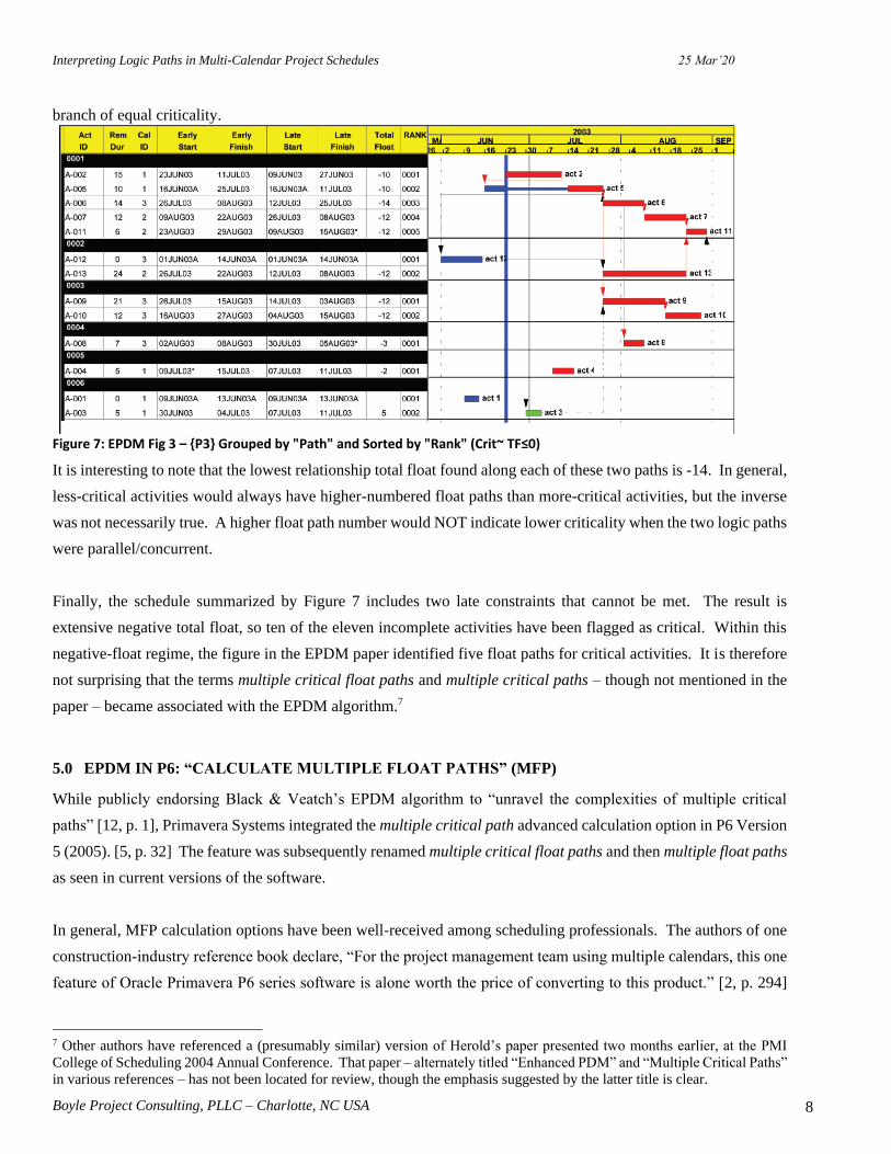
The EPDM output that Herold proposed is summarized in Figure 7, where float path 0001 includes five activities
with three different values of total float (due to calendar switching), and float path 2 constitutes a parallel logic
Interpreting Logic Paths in Multi-Calendar Project Schedules 25 Mar’20
Boyle Project Consulting, PLLC – Charlotte, NC USA 8
branch of equal criticality.
Figure 7: EPDM Fig 3 – {P3} Grouped by "Path" and Sorted by "Rank" (Crit~ TF≤0)
It is interesting to note that the lowest relationship total float found along each of these two paths is -14. In general,
less-critical activities would always have higher-numbered float paths than more-critical activities, but the inverse
was not necessarily true. A higher float path number would NOT indicate lower criticality when the two logic paths
were parallel/concurrent.
Finally, the schedule summarized by Figure 7 includes two late constraints that cannot be met. The result is
extensive negative total float, so ten of the eleven incomplete activities have been flagged as critical. Within this
negative-float regime, the figure in the EPDM paper identified five float paths for critical activities. It is therefore
not surprising that the terms multiple critical float paths and multiple critical paths – though not mentioned in the
paper – became associated with the EPDM algorithm.7
5.0 EPDM IN P6: “CALCULATE MULTIPLE FLOAT PATHS” (MFP)
While publicly endorsing Black & Veatch’s EPDM algorithm to “unravel the complexities of multiple critical
paths” [12, p. 1], Primavera Systems integrated the multiple critical path advanced calculation option in P6 Version
5 (2005). [5, p. 32] The feature was subsequently renamed multiple critical float paths and then multiple float paths
as seen in current versions of the software.
In general, MFP calculation options have been well-received among scheduling professionals. The authors of one
construction-industry reference book declare, “For the project management team using multiple calendars, this one
feature of Oracle Primavera P6 series software is alone worth the price of converting to this product.” [2, p. 294]
7 Other authors have referenced a (presumably similar) version of Herold’s paper presented two months earlier, at the PMI
College of Scheduling 2004 Annual Conference. That paper – alternately titled “Enhanced PDM” and “Multiple Critical Paths”
in various references – has not been located for review, though the emphasis suggested by the latter title is clear.

Interpreting Logic Paths in Multi-Calendar Project Schedules 25 Mar’20
Boyle Project Consulting, PLLC – Charlotte, NC USA 9
A key recommended practice of AACE International also lists MFP analysis (using both of its earlier names) as one
of three potential methods for identifying near-critical paths in project schedules. In particular:
Calculating multiple paths using the “free float” setting will result in a primary critical path that is
identical to the critical path displayed when critical activities are defined as the longest path. All
subsequent float paths will be increasingly distant float paths from the longest path. The amount of
difference between float paths (or measure of near‐criticality) is not presented but may be inferred using
total float. [9, p. 10]
In the most recent study, authors Kelly and Nelson performed a detailed review and analysis of MFP applications
in single-calendar projects, demonstrating the consequences of the various user options and examining the
calculations in detail. [3, pages 14-22] The analysis was supported by extensive reference to detailed support
documentation and help files from Oracle. In general, the authors made the following key observations:
• In large, real-world projects, it is common to identify multiple, parallel branches of the Longest Path,
which MFP analysis (either Total-Float or Free-Float option) differentiates into sequentially-numbered
float paths. Existing Oracle documentation – and a casual reading of other authoritative documents that
are based on it – suggest that only the first of these paths is truly (“the most”) critical and that all the rest
are incrementally less critical than the first. This is often incorrect; the float path numbering in such cases
may be considered essentially arbitrary with respect to the potential impact on project completion.
• When the total float option is used, float path assignments are affected by late date constraints. As a
result, some LP activities may be relegated to high-numbered paths, and some non-LP activities may be
found on low-numbered paths. Thus, the total float option does not define a single critical path for a
project with late date constraints.
• Activities with as-late-as-possible (ALAP) constraints routinely appear as driving predecessors in P6.
Consequently, ALAP-constrained activities can be over-represented in the lower numbered (i.e. more
critical) float paths, displacing other activities to higher-numbered paths. (Applying filters to hide
ALAP-constrained activities in float path layouts is a common, if imperfect, response to this issue.)
• The Oracle-documented tie-breaking rules for path tracing and path numbering in Free-Float analyses
could be verified in a standard example project.
The authors concluded that MFP analysis is a useful tool for analyzing and understanding the logic of the schedule,
but the repeated Oracle references to a single “most-critical” path and multiple “sub-critical” paths are incorrect.
Such references permeate the documents and have been repeated by other respected authors. [3, 22] The authors
further concluded, “(T)he longest path remains the correct definition of critical path, and total float values in a
network without finish constraints remains the best way to gauge an activity’s proximity to the critical path. While
the float path values do provide useful information about the CPM network to analysts and schedulers alike, those
values do not represent a ranked order of criticality.”
6.0 MULTIPLE FLOAT PATH CALCULATION
The mathematical algorithm for calculating multiple critical paths is proprietary, and Oracle resources – including
online help files and other technical documents available to users – provide minimal and sometimes contradictory
information. Nevertheless, the following key points of understanding are evident from the available information,

Interpreting Logic Paths in Multi-Calendar Project Schedules 25 Mar’20
Boyle Project Consulting, PLLC – Charlotte, NC USA 10
complemented by detailed evaluation of calculation results.
MFP Terms
P6’s MFP calculation treats logic relationships similarly to activities, but with their durations equal to the specified
lags, and with all finish-to-start links. Consequently, early and late dates for each relationship can be calculated
during the forward and backward passes. For relationships without lags, P6 uses the predecessor activity’s calendar
to compute early dates (RES, REF) during the forward pass, and it uses the successor’s calendar to compute late
dates (RLS, RLF) during the backward pass.8 The calculations also incorporate the effects of the lag calendar (from
P6’s calculation options) when non-zero lags are introduced. With the relationship early and late dates established
during the network calculations, float values can be computed.
As noted during the earlier discussion of driving logic, the interpretation of relationship float values is substantially
affected by the calendar used in the float computations. P6 therefore computes relationship floats using both
predecessor and successor calendars. In addition to early and late dates, each relationship possesses the following
float values:
• relationship total float (RTF) = RLS - RES [using the predecessor’s calendar]9
• relationship successor total float (RSTF) = RLF - REF [using the successor’s calendar]10
• relationship free float (RFF) = (successor activity ES/EF) - REF [using predecessor’s calendar]
• relationship successor free float (RSFF) = (successor activity ES/EF) - REF [using successor’s calendar]
As implied by their common preface, all of these terms are properties of specific relationships, NOT of the two
associated schedule activities. In general, activities can be associated with multiple relationships – and thus,
multiple values of relationship floats. Consequently, a reference to an activity having or possessing a particular
relationship float value is ambiguous.11
Since relationship float values are closely related to driving logic in project schedules, P6 uses them to identify and
trace the driving logic float paths in the MFP calculation. The key difference between their usage is that the free
floats (RFF and RSFF) are associated with driving logic to early dates only, while the total floats (RTF and RSTF)
reflect less-conventional bi-directional driving logic; i.e. to both early and late dates, as spelled out by Herold in the
8 Oracle defines RES, REF, RLS, and RLF with reference to “the relationship calendar” – a term that is not otherwise defined.
[13, p. 3] In practice, the dates for zero-lag relationships behave as described here. For positive-lag relationships, then only
REF and RLS are constrained by the “relationship lag calendar” schedule option. 9 Oracle defines relationship total float as, “The Total Float on the relationship. Calculated as Relationship Late Start –
Relationship Early Start on the successor’s calendar....” [13, p. 3] The last part appears incorrect. As easily inferred from
Figure 2, RTF is computed using the predecessor’s calendar, not the successor’s. 10 Oracle documentation states, “The relationship successor Total Float is the total float of the potential successor activity if
that specific relationship was the driving relationship, using the successor’s calendar...” [13, pp. 3-4] – though how this would
be calculated for non-driving relationships is not clear. Harold’s paper derived and used a similar term, “resulting successor
TF” (RSTF), for the same purpose. Essentially, Harold’s RSTF = RLF - REF [using the successor’s calendar]. 11 E.g. “…the module determines which predecessor activity has the most critical Relationship Total Float on the backward
pass.” [13, p. 2]

Interpreting Logic Paths in Multi-Calendar Project Schedules 25 Mar’20
Boyle Project Consulting, PLLC – Charlotte, NC USA 11
EPDM paper. [11, pp. 5-6] Adapting Herold’s description to P6 terminology, a relationship is bi-directionally
driving when:
• RTF = TF(predecessor activity) (Backward driving, i.e. predecessor’s late dates are driven by the relationship),
AND
• RSTF = TF(successor activity) (Forward driving, i.e. successor’s early dates are driven by the relationship. As
noted earlier, such relationships also have RSFF=0).
The actual application of the terms in identifying and tracing multiple float paths in P6 depends on the options
selected by the user.
Float Path Numbering
The primary artifact of the MFP calculation is the assignment of individual activities (and some relationships) to
specific numbered float paths. Each float path is calculated in two steps. First, the float path is initiated by a starting
(or seed) relationship. Then the rest of the float path is defined by tracing driving logic backward (and sometimes
forward) from the seed relationship, assigning the traced activities and relationships to the numbered float path.
The trace ends (in a given direction) when the activity being examined has no driving relationships with any
unassigned activities.
P6 calculates these numbered float paths sequentially and without overlap, such that the calculation of float path 2
cannot commence until float path 1 has been completely defined. Unlike recursive logic tracing algorithms used in
other tools, MFP does not explicitly address the logic junctions between paths. When an activity with multiple
driving relationships is encountered during a float path trace, only one of the relationships is included in the trace.
The others are relegated to compete for seeding subsequent float paths. This approach makes MFP computations
very efficient. It also leads to ambiguous float path definitions under certain (typically multi-calendar) conditions,
to be discussed later in this paper.
Float Path Order
A secondary artifact of the MFP calculation is the unique sequence-numbering of the individual activities in each
float path. P6 calls this sequence numbering the float path order of the activity. For each path, the single activity
with no unassigned driving predecessors is the first activity in the logical sequence; it has a float path order of 1.
The single activity with no unassigned successors is the last activity in the logical sequence; it has the highest float
path order, which equals the total number of activities in the path. Float path orders for the intervening activities
are assigned accordingly. Since P6 reserves float path order to the sequence of tasks within a particular float path,
any use of the same or similar term in reference to the sequential numbering of float paths would be ambiguous.12
12 E.g. “When Using the Total Float Option: There are new key fields used to determine multiple float path order….” [13,
pp. 2-3] Although the language of this document is vague, this section’s two references to “float path order” appear to address
path seeding (i.e. float path sequential values), not tracing.

Interpreting Logic Paths in Multi-Calendar Project Schedules 25 Mar’20
Boyle Project Consulting, PLLC – Charlotte, NC USA 12
Display of MFP Results
The following display techniques – typically saved as a single layout in P6 – are generally useful for interpretation
and communication of MFP results in multi-calendar project schedules:
• Within a Gantt chart top view, activities are grouped by project and then by float path. Then within each
float path the activities are sorted by float path order.
• With the activity details shown on the bottom pane, the columns of the predecessor and successor tables
are customized to include all of the multiple float path fields. (The float fields are most useful.) Right-
justification facilitates condensing the columns while still distinguishing the necessary information.
• Often for production reports, a filter is applied to display only activities with float paths assigned or with
float paths below a specified value. (For clarity, no such filters are applied here.)
7.0 MFP CALCULATION OPTIONS
As shown in Figure 8, multiple float paths may be calculated using total float or free float options, and a key ending
activity may be specified (or omitted) for each option. These combinations lead to four basic calculation methods.
(Only the first of these – total float with no ending activity – was demonstrated in the EPDM paper.)
Figure 8: MFP Options Dialog
Number of Paths to Calculate
The four calculation methods may each be truncated by specifying a limit on the number of paths to calculate. This
number has no impact on the seeding or tracing of individual float paths at or below the limit. Activities that would
normally be assigned to float paths above the limit simply have no float path assigned.
Since float path assignments can be ambiguous, any entry here increases the risk that important float paths may be
missed or overlooked. Unless the schedule is so large that truncating the analysis is necessary to provide reasonable
computation time (a situation never encountered by the authors), it is better to leave this option blank, and use
appropriate filtering to de-clutter the output.
Interpreting Logic Paths in Multi-Calendar Project Schedules 25 Mar’20
Boyle Project Consulting, PLLC – Charlotte, NC USA 13
Ending Activity
When an ending with activity is specified, then the entire MFP analysis including float path assignment is restricted
to activities and relationships that are path-predecessors of the specified activity. (These can be flagged during the
backward pass). This option can be useful for validating the logical consistency of the schedule. E.g., specifying
one of the project’s key completion milestones as the ending activity (with no limit on the number of paths) quickly
identifies those activities with no float path that:
• Have no successors at all; or
• Have successors but have been logically disconnected from the completion plan for the milestone.
The fact that any of these activities could be allowed to slip indefinitely without delaying the key completion
milestone often indicates inadequate logic. Further interpretation of the ending activity depends on whether the
total float or free float option is selected.
Total Float Option
Choose this option to identify critical paths based on the total float of activity relationships…. [14, p.1]
The total float option reflects P6’s implementation of the Enhanced PDM algorithm outlined in Herold’s paper. It
is characterized by the following key attributes:
• Total float is accepted as the sole indicator of an activity or relationship’s logical importance, or
criticality.
• Any driving logic path whose activities have different values of total float due to calendar switching is
consolidated into a single float path.
• Parallel logic paths – with or without calendar-switching effects – are segregated into separate float paths.
• Float path 1 is seeded by the logic relationship with the lowest relationship total float in the project. (As a
pre-qualifier, this relationship must be a path-predecessor of the specified ending activity, and some other
tie-breakers apply.)
• Each successive float path is seeded by a pre-qualified relationship with the lowest relationship total float.
(Some tie-breakers apply.)
• Once seeded, each float path is defined by tracing bi-directionally driving logic backward AND forward
from the seed relationship.
• When grouped and sorted as suggested earlier, total float values generally increase as float path numbers
increase. Logical connections between float paths do not follow a predictable pattern, however,
especially in the presence of multiple calendars and intersecting logic.
• The primary impact of specifying an ending activity is the exclusion of activities and relationships that are
not path predecessors of the specified activity. Float path 1 (and adjacent concurrent float paths) may
reliably reflect the driving path to the specified activity only when that activity controls the late dates of
all its predecessors (i.e. there are no intersecting logic paths or late constraints.)
Overall, the total float option seems most useful for two very different use cases:
• Prioritizing competing workflows in extremely complex schedules involving multiple calendars,
intersecting logic paths, and multiple constrained milestones of equal value. Such projects are relatively
rare.

Interpreting Logic Paths in Multi-Calendar Project Schedules 25 Mar’20
Boyle Project Consulting, PLLC – Charlotte, NC USA 14
• Defining near-critical paths in complex schedules with multiple calendars and intersecting logic paths, but
with only a single constrained completion milestone. Such schedules are common in simple construction
projects. In P6, the critical path of such projects is typically defined by Longest Path.
Free Float Option
Choose this option to define critical float paths based on longest path…. [14, p.1]
Like P6’s Longest Path criterion for criticality, the free float option defines float paths by backward-tracing through
driving relationships. It is characterized by the following key attributes:
• Relationship free float and relationship successor free float are accepted as the primary indicators of an
activity or relationship’s logical importance, or criticality. Total float is generally ignored.
• As for the previous option, any driving logic path is consolidated into a single float path regardless of
total float values.
• As for the previous option, parallel driving logic paths are segregated into separate float paths.
• If an ending activity is specified, then float path 1 is seeded by the specified activity. If no ending activity
is specified, then float path 1 is seeded by the open-ended activity with the lowest free float.13
• Each successive float path is seeded by a pre-qualified relationship with the lowest relationship free float
(RFF).14 (Some tie-breakers apply.)
• Once seeded, each float path is defined by tracing traditional driving (i.e. early-dates) logic backward
from the seed relationship. Such driving logic is defined by relationship successor free float (RSFF=0).15
• When grouped and sorted as suggested earlier, each float path typically appears as a branch extending
backward from one of the paths above it.
• As a result of the differing criteria for seeding (RFF) versus tracing (RSFF) driving logic paths, the
parallel branches of driving paths in projects with multiple atypical calendars can be separated and
relegated to much higher-numbered float paths than expected.
• The primary impact of specifying an ending activity is the explicit definition of the end-point of the
driving and near-driving logic paths being traced. Then float path 1 (and concurrent float paths) reliably
reflect the driving path to the specified activity under most practical conditions.
Overall, the free float option can provide clear, well-supported results in most cases, and it seems to be preferred
by most users. Its use seems particularly valid for the following cases:
• Identifying the driving and near-driving logic paths to a primary ending-with activity – e.g. a Substantial
Completion milestone – that defines the project’s performance period but is not the final activity in the
schedule.
• Identifying the driving and near-driving logic paths to intermediate project milestones or other important
activities.
• Together with Longest Path, identifying the distinct, parallel logic branches that drive the project’s
completion date.
13 Or more correctly – in both cases – an imaginary successor relationship following the activity. 14 In the absence of an ending-with activity, then the imaginary successor relationship following each open-ended activity
competes to seed the successive float paths. 15 A different procedure is described in the documentation: “1. Free Float is calculated on the activity 2. Next it will look at the
predecessor activities to see if FF and RSFF match 3. Once it finds a predecessor where the RSFF and FF are different the first
path ends there 4. Once that path is determined it looks at the next activity with the least FF and starts again.” [13, p. 3] This
is unreliable, as P6 behavior in the shop test example below does not match.
Interpreting Logic Paths in Multi-Calendar Project Schedules 25 Mar’20
Boyle Project Consulting, PLLC – Charlotte, NC USA 15
• Together with Longest Path, identifying critical and near-critical paths (to a key completion milestone) in
complex schedules with multiple calendars, intersecting logic paths, AND multiple late constraints.
Unlike the previous option, the nearness to the critical path is not readily defined by total float. Manual
reference to the relationship free floats of selected relationships is necessary.
8.0 SUMMARY OF MFP EXAMPLES AND INTERPRETATIONS
EPDM Example, From Herold
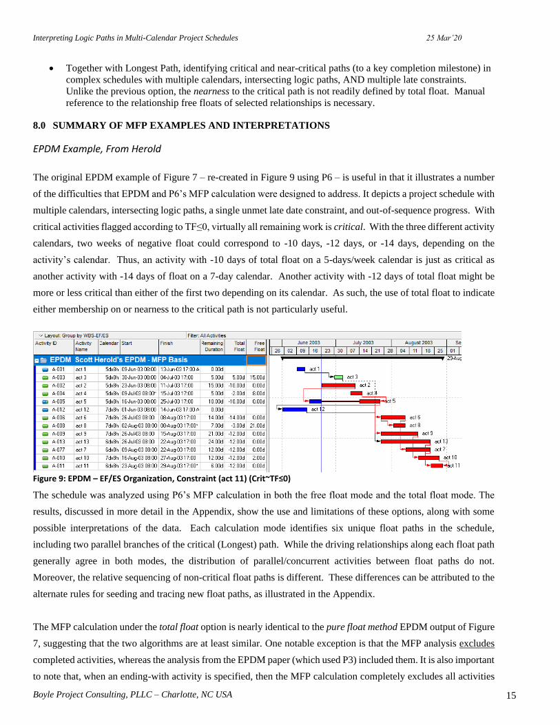
The original EPDM example of Figure 7 – re-created in Figure 9 using P6 – is useful in that it illustrates a number
of the difficulties that EPDM and P6’s MFP calculation were designed to address. It depicts a project schedule with
multiple calendars, intersecting logic paths, a single unmet late date constraint, and out-of-sequence progress. With
critical activities flagged according to TF≤0, virtually all remaining work is critical. With the three different activity
calendars, two weeks of negative float could correspond to -10 days, -12 days, or -14 days, depending on the
activity’s calendar. Thus, an activity with -10 days of total float on a 5-days/week calendar is just as critical as
another activity with -14 days of float on a 7-day calendar. Another activity with -12 days of total float might be
more or less critical than either of the first two depending on its calendar. As such, the use of total float to indicate
either membership on or nearness to the critical path is not particularly useful.
Figure 9: EPDM – EF/ES Organization, Constraint (act 11) (Crit~TF≤0)
The schedule was analyzed using P6’s MFP calculation in both the free float mode and the total float mode. The
results, discussed in more detail in the Appendix, show the use and limitations of these options, along with some
possible interpretations of the data. Each calculation mode identifies six unique float paths in the schedule,
including two parallel branches of the critical (Longest) path. While the driving relationships along each float path
generally agree in both modes, the distribution of parallel/concurrent activities between float paths do not.
Moreover, the relative sequencing of non-critical float paths is different. These differences can be attributed to the
alternate rules for seeding and tracing new float paths, as illustrated in the Appendix.
The MFP calculation under the total float option is nearly identical to the pure float method EPDM output of Figure
7, suggesting that the two algorithms are at least similar. One notable exception is that the MFP analysis excludes
completed activities, whereas the analysis from the EPDM paper (which used P3) included them. It is also important
to note that, when an ending-with activity is specified, then the MFP calculation completely excludes all activities

Interpreting Logic Paths in Multi-Calendar Project Schedules 25 Mar’20
Boyle Project Consulting, PLLC – Charlotte, NC USA 16
and relationships that cannot be traced backward from that activity. If, as is the case with this example, the total
float values of activities and relationships are controlled by a constraint that is not applied to the ending-with
activity, it is difficult to discern a relationship between the total float values and the driving relationships. The result
demonstrates why the total float option with an ending activity is rarely useful and can be misleading.
This example demonstrates that both calculation modes can be useful for clarifying critical and near-critical logic
paths in a schedule that is complicated by multiple calendars, negative float, and out-of-sequence progress. In some
cases, total float may be controlled by a small number of rigidly enforced late date constraints, and violation of any
single constraint is equally unacceptable to the project team. In these cases, MFP analysis using the total float
option and NO ending-with activity may be most useful for prioritizing the remaining work. With or without an
ending activity, however, the total float option is not useful for defining the driving/controlling logic for activities
away from the critical path. In contrast, the free float option is generally preferred for defining the driving logic to
a specific ending activity, especially one that is far from critical.
Finally, it is confirmed that the suggestion of a single most critical path followed by a number of sub-critical paths
is not supported in general, even in the project example that seems to have originated this particular terminology.
For both calculation options, it is important to remember that the detailed seeding and tracing of float paths are
governed primarily by relationship floats, NOT activity floats. As a result, inspection of activity total float and free
float fields in a typical MFP output plot may sometimes be misleading. Reference to the detailed relationship
parameters, though tedious, is absolutely necessary to determine whether one float path is in fact more critical than
the next.
Unaligned Calendars – Shop Work
Although it provides a good demonstration of the MFP calculation in a project with simple and well-aligned
calendars, the EPDM example does not reflect the full gamut of calendar variations observed in modern project
schedules. In particular, the consequences of calendar switching among the 5-day, 6-day, and 7-day calendars used
in the EPDM example are manifested almost exclusively in total float (rather than free float) values. Other calendar
types in construction include 24-hour/curing; weather/rain (both distributed and lumped); day/night shift; calendars
with annual/seasonal shutdowns for social or environmental restrictions; and calendars with specific black-out times
for external events. In other industries, resource-driven activities are used to incorporate the planned holidays and
vacations times of individual resources; and calendars for rare, periodic work periods like board meetings are used
to accurately model the potential schedule impact of missing such approval windows. Such calendars are often not
well-aligned with the typical work-week calendar, and there is a greater chance of non-intuitive float-switching
along driving logic paths. Consequently, the depiction of parallel/concurrent driving logic paths can be confused.
Figure 10 presents the complexities of such unaligned calendars, using a simple Shop Work example. The core

Interpreting Logic Paths in Multi-Calendar Project Schedules 25 Mar’20
Boyle Project Consulting, PLLC – Charlotte, NC USA 17
work of this project involves three parallel machining operations followed by a simple assembly operation. All
relationships are finish-to-start, and there are no lags, constraints, open-ended activities, or reported progress.
Figure 10: Shop Work – EF/ES Organization, No Constraint (Crit~LP)
The primary complication is that the eleven activities employ five different calendars. The final assembly and sign
off of the finished product are performed by resources working a normal 5-day work week, but the planning,
machining, and cleanup activities are all performed according to calendars whose available working hours –
especially spanning the weekend – are substantially more or less than the standard. For example, all four machining
activities finish at various times over the weekend; they are all included on the Longest Path because each of them
is a driving predecessor of the subsequent assembly activity. The assembly planning activity is not on the Longest
Path, but one day of delay – according to its own calendar – could delay the project for a week. The figure
demonstrates no clear correlation between activity float values and membership on the Longest Path. A simple
construction example demonstrating similar issues might involve mixed concrete and asphalt construction spanning
a winter paving shutdown period – perhaps with monthly meetings of a change-review board added into the mix.
As detailed in the Appendix, six or seven float paths were identified from this schedule using the free float and total
float modes, respectively. The majority of the float paths were comprised of only a single activity each. Most
importantly, in both modes non-critical activities have displaced several parallel branches of the critical (Longest)
Path to higher-numbered float paths. Consistent with prior conclusions, the float paths are not correlated with
activity float values, so reference to relationship floats is needed to characterize the basis for and relative criticality
of each float path.
The Appendix shows the detailed tracing of each of the float paths and demonstrates how the various tie breakers
are applied to assign float path numbers based on, for example, the Activity ID’s sorted alphanumerically. For the
total float option in particular, the resulting float path assignments are confused and fragmented. The detailed
analysis also confirms the previously-noted limitations on the use of an ending-with activity with the total float
option; it is rarely useful and can be misleading.
This example demonstrates that P6’s proprietary algorithms for seeding and tracing float paths are more nuanced
than might be suggested by the initial (EPDM) paper or by the user documentation. In particular, the rules for
preferring or pre-qualifying specific activities and relationships prior to tie-breaker testing – when parallel driving

Interpreting Logic Paths in Multi-Calendar Project Schedules 25 Mar’20
Boyle Project Consulting, PLLC – Charlotte, NC USA 18
logic is most likely – remain unclear.
More importantly, the example demonstrates the fragmentation and dispersal of the Longest Path – with some
parallel branches relegated to float paths much higher than expected – when multiple calendars are not perfectly
aligned. The fragmentation is the result of conflicts between the criteria for driving path tracing (which depend
partly or wholly on successor calendars) and the criteria for path seeding (which depend primarily on predecessor
calendars). This phenomenon exists with both total float and free float options, and it provides the primary argument
against specifying any limit on the number of float paths to be analyzed. Unfortunately, the observation of such
fragmentation – whether on the Longest Path, the float-defined critical path, or on the driving path to some other
ending activity – means that the entire float path sequence resulting from the MFP analysis may be essentially
unreliable.
The shop work example is not representative of typical construction or fabrication projects, and it was developed
explicitly to explore the behavior of P6’s MFP analysis in schedules with multiple, unaligned calendars. While
some limits to the validity of MFP analysis are evident, these appear to exist primarily in edge-case conditions like
those of the example.
9.0 OVERALL CONCLUSIONS
The interpretation of driving schedule logic in modern project schedules, including the associated critical- and near-
critical paths, is often complicated by multiple calendars and other factors. P6’s multiple float path analysis option
was developed to provide the needed clarity when these conditions are present.
The primary value of MFP analysis is in providing an intuitive graphical arrangement of schedule logic, revealing
driving and near driving paths that are otherwise obscured, namely:
• Separate and distinct float paths that share the same value of total float;
• Single float paths with multiple values of total float.
These are of primary importance to forward-looking managers of complex projects.
The free float option is useful for general-purpose identification and tracing of driving and near-driving logic paths
to a specified project completion activity, to specified intermediate project milestones, or to any other important
activities in the schedule. Like P6’s Longest Path, it evaluates early dates only, ignoring late constraints and total
float. This option is more likely to provide understandable results when an ending activity is specified.
The total float option is primarily useful – especially together with Longest Path – for defining critical and near-
critical paths in unconstrained projects with multiple calendars. It is also useful for prioritizing workflows in overly-
constrained project schedules with multiple calendars. In either case, no ending activity should be specified.
Interpreting Logic Paths in Multi-Calendar Project Schedules 25 Mar’20
Boyle Project Consulting, PLLC – Charlotte, NC USA 19
Although the bi-directional driving logic calculations of this option are nominally more restrictive than the
conventional driving logic calculations of the free float option, the observed results appear no more valid (nor less
arbitrary) in the examples studied. Because its results can be confusing or misleading under many conditions, the
total float option is less preferred for general-purpose use.
Our observations have confirmed the main conclusion of the earlier study. Namely, float path number alone is not
a reliable indicator of the criticality of any particular activity or path. Although some overall patterns can be
observed, conclusions of relative criticality require detailed and nuanced review of the underlying relationship data.
For multi-calendar projects in particular, parallel branches of driving logic paths can become fragmented and widely
separated. Under such conditions, members of the Longest Path (i.e. driving activities to project completion) can
be displaced to much higher float paths by non-Longest Path activities with different calendars. When such
displacements are observed, then the overall validity of the analysis should be questioned.16
As an accessory feature, MFP analysis also provides the most expedient method to filter schedule activities based
on a common path-successor. Such filters are necessary to confirm the vertical and horizontal integration of
complex schedules. For example, if an activity is included within a particular branch of the work breakdown
structure (WBS) but is excluded from the float paths leading to the corresponding WBS completion milestone, then
the activity is likely missing some important successor logic.
Finally, our study revealed instances where the existing Oracle documentation may require revision. Most
importantly, Oracle documentation repeatedly refers to float path 1 as the most critical path and to all higher-
numbered float paths as sub-critical paths. Clearly this fails to account for the parallel logic branches that are
common in project schedules – and which were even present in the foundational EPDM paper that introduced the
method. In other places, “most critical” seems to have been substituted for more precise language (e.g. “lowest
relationship total float equaling the predecessor activity total float”) in a number of user-facing documents. While
such simplifications may be useful for introducing elementary concepts, they do not foster understanding of the
underlying methods.
In addition, we have identified a number of cases (generally in footnotes) where the core documentation of the MFP
analysis is either imprecise, is directly at odds with known good practice, or is not supported by the observed
behavior of the software. Even though the underlying methods are proprietary, it seems reasonable to expect some
improvement in the consistency of the documents.
16 Displacement of Longest Path activities to higher-numbered float paths can also be the result when the activities are wrongly
included on the Longest Path due to malformed level-of-effort activities. (MFP analysis correctly excludes such activities from
the driving path to project completion.)

Interpreting Logic Paths in Multi-Calendar Project Schedules 25 Mar’20
Boyle Project Consulting, PLLC – Charlotte, NC USA 20
10.0 REFERENCES
1 AACE International, “Cost Engineering Terminology,” Recommended Practice 10S90, AACE
International, Morgantown, WV, USA (2019).
2 O’Brien, James J., and Plotnick, Fredric L., CPM in Construction Management, Eighth Edition,
McGraw Hill Professional, New York, NY, USA, 2015.
3 Kelly Patrick M., and Nelson Roger, “Primavera’s Float Path Calculation: Review and Analysis of
Applications,” Cost Engineering, January/February 2019, AACE International, Morgantown, WV,
USA, 2019.
4 Carson, Christopher, Oakander, Peter, and Relyea, Craig (eds), CPM Scheduling for Construction –
Best Practices and Guidelines, Project Management Institute, Newtown Square, PA, USA, 2014.
5 Winter, Ron, “The Inner Workings of Oracle/Primavera P6TM,” PS-2063, 2015 AACE International
Transactions, AACE International, Morgantown, WV, USA, 2015.
6 Ponce de Leon, Gui, “GPM® and forensic total float,” Paper presented at PMI Global Congress
2010 – North America, Washington, DC
Project Management Institute, Newtown Square, PA, USA, 2010.
7 Winter, Ron, “Longest Path Value (to the Rescue),” 2004 Primavera Annual Conference
Proceedings, Primavera Systems, Inc., Bala Cynwyd, PA, USA, 2004.
8 Oracle Corporation, “Business Rule Utilized By P6 to Define Driving and Non-driving
Relationships,” Doc ID 2147003.1, support.oracle.com.[Online] Published March 28, 2019. [Cited:
September 1, 2019.], Oracle, Redwood Shores, CA, USA, 2019.
9 AACE International, “Identifying the Critical Path,” Recommended Practice 49R-06, AACE
International, Morgantown, WV, USA, 2010.
10 Oracle Corporation, “How is the Longest Path Determined in Project Management,” Doc ID
894149.1, support.oracle.com.[Online] Published February 13, 2019. [Cited: September 3, 2019],
Oracle, Redwood Shores, CA, USA, 2019.
11 Herold, Scott C., “’Enhanced’ PDM - Concepts and Benefits,” PS.09, 2004 AACE International
Transactions, AACE International, Morgantown, WV, USA, 2004.
12 Primavera Systems, Inc., “Primavera Customers Honored with Constructech Vision Awards (Press
Release),” [Online] https://www.businesswire.com/news/home/20061003005217/en/Primavera-
Customers-Honored-Constructech-Vision-Awards [Cited September 4, 2019], BusinessWire, New
York, NY, USA, 2006.
13 Oracle Corporation, “Multiple Float Paths Explained Including How to Use Multiple Float Paths in
P6,” Doc ID 904945.1, support.oracle.com.[Online] Published July 1, 2019. [Cited: August 23,
2019], Oracle, Redwood Shores, CA, USA, 2019.
14 Oracle Corporation, “Advanced tab – Schedule Options dialog box,” Oracle Primavera P6
Professional Help Version 18. [Online] November 30, 2018. [Cited 11 Sept 2019], Oracle,
Redwood Shores, CA, USA, 2018.
Interpreting Logic Paths in Multi-Calendar Project Schedules 25 Mar’20
Boyle Project Consulting, PLLC – Charlotte, NC USA 21
11.0 APPENDIX – DETAILS OF MFP EXAMPLES AND INTERPRETATIONS

Interpreting Logic Paths in Multi-Calendar Project Schedules - APPENDIX 25 Mar’20
Boyle Project Consulting, PLLC – Charlotte, NC USA i
DETAILS OF MFP EXAMPLES AND INTERPRETATIONS
Appendix Table of Contents
INTRODUCTION .............................................................................................................................. 1
EPDM EXAMPLE, FROM HEROLD ............................................................................................... 1
EPDM EXAMPLE – FREE FLOAT OPTION ................................................................................ 1
EPDM EXAMPLE – TOTAL FLOAT OPTION .............................................................................. 4
EPDM EXAMPLE – ENDING-WITH ACTIVITY ........................................................................... 5
EPDM EXAMPLE - CONCLUSIONS ........................................................................................... 7
UNALIGNED CALENDARS – SHOP WORK ................................................................................. 8
SHOP WORK – FREE FLOAT OPTION ........................................................................................ 9
SHOP WORK – TOTAL FLOAT OPTION .................................................................................... 10
SHOP WORK – ENDING-WITH ACTIVITY ................................................................................. 12
SHOP WORK EXAMPLE - CONCLUSIONS ................................................................................. 14
Interpreting Logic Paths in Multi-Calendar Project Schedules - APPENDIX 25 Mar’20
Boyle Project Consulting, PLLC – Charlotte, NC USA 1
INTRODUCTION
As a supplement to the primary report, this document provides detailed descriptions, observations, and potential
interpretations of multiple float path (MFP) calculations in two simplified project schedule examples.
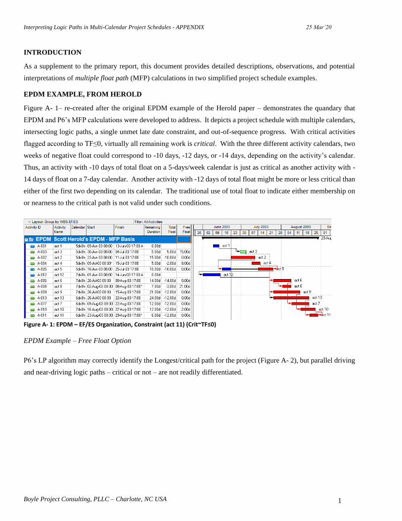
EPDM EXAMPLE, FROM HEROLD
Figure A- 1– re-created after the original EPDM example of the Herold paper – demonstrates the quandary that
EPDM and P6’s MFP calculations were developed to address. It depicts a project schedule with multiple calendars,
intersecting logic paths, a single unmet late date constraint, and out-of-sequence progress. With critical activities
flagged according to TF≤0, virtually all remaining work is critical. With the three different activity calendars, two
weeks of negative float could correspond to -10 days, -12 days, or -14 days, depending on the activity’s calendar.
Thus, an activity with -10 days of total float on a 5-days/week calendar is just as critical as another activity with -
14 days of float on a 7-day calendar. Another activity with -12 days of total float might be more or less critical than
either of the first two depending on its calendar. The traditional use of total float to indicate either membership on
or nearness to the critical path is not valid under such conditions.
Figure A- 1: EPDM – EF/ES Organization, Constraint (act 11) (Crit~TF≤0)
EPDM Example – Free Float Option
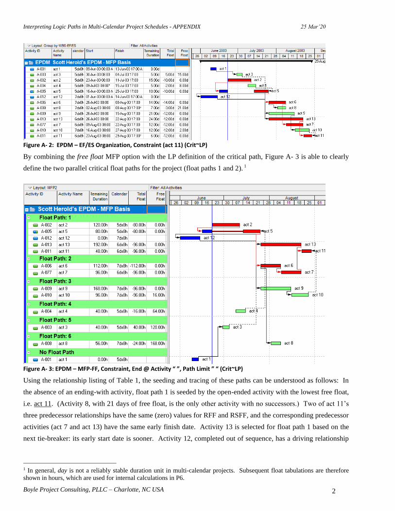
P6’s LP algorithm may correctly identify the Longest/critical path for the project (Figure A- 2), but parallel driving
and near-driving logic paths – critical or not – are not readily differentiated.
Interpreting Logic Paths in Multi-Calendar Project Schedules - APPENDIX 25 Mar’20
Boyle Project Consulting, PLLC – Charlotte, NC USA 2
Figure A- 2: EPDM – EF/ES Organization, Constraint (act 11) (Crit~LP)
By combining the free float MFP option with the LP definition of the critical path, Figure A- 3 is able to clearly
define the two parallel critical float paths for the project (float paths 1 and 2). 1
Figure A- 3: EPDM – MFP-FF, Constraint, End @ Activity “ ”, Path Limit ” “ (Crit~LP)
Using the relationship listing of Table 1, the seeding and tracing of these paths can be understood as follows: In
the absence of an ending-with activity, float path 1 is seeded by the open-ended activity with the lowest free float,
i.e. act 11. (Activity 8, with 21 days of free float, is the only other activity with no successors.) Two of act 11’s
three predecessor relationships have the same (zero) values for RFF and RSFF, and the corresponding predecessor
activities (act 7 and act 13) have the same early finish date. Activity 13 is selected for float path 1 based on the
next tie-breaker: its early start date is sooner. Activity 12, completed out of sequence, has a driving relationship
1 In general, day is not a reliably stable duration unit in multi-calendar projects. Subsequent float tabulations are therefore
shown in hours, which are used for internal calculations in P6.
Interpreting Logic Paths in Multi-Calendar Project Schedules - APPENDIX 25 Mar’20
Boyle Project Consulting, PLLC – Charlotte, NC USA 3
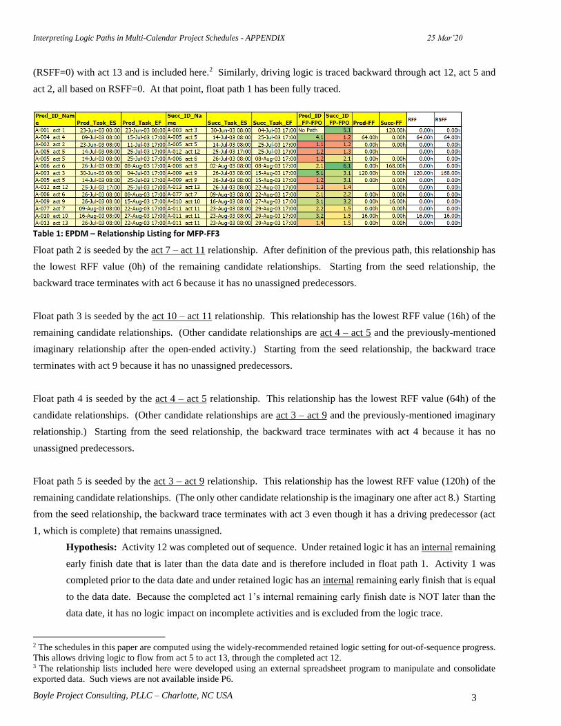
(RSFF=0) with act 13 and is included here.2 Similarly, driving logic is traced backward through act 12, act 5 and
act 2, all based on RSFF=0. At that point, float path 1 has been fully traced.
Table 1: EPDM – Relationship Listing for MFP-FF3
Float path 2 is seeded by the act 7 – act 11 relationship. After definition of the previous path, this relationship has
the lowest RFF value (0h) of the remaining candidate relationships. Starting from the seed relationship, the
backward trace terminates with act 6 because it has no unassigned predecessors.
Float path 3 is seeded by the act 10 – act 11 relationship. This relationship has the lowest RFF value (16h) of the
remaining candidate relationships. (Other candidate relationships are act 4 – act 5 and the previously-mentioned
imaginary relationship after the open-ended activity.) Starting from the seed relationship, the backward trace
terminates with act 9 because it has no unassigned predecessors.
Float path 4 is seeded by the act 4 – act 5 relationship. This relationship has the lowest RFF value (64h) of the
candidate relationships. (Other candidate relationships are act 3 – act 9 and the previously-mentioned imaginary
relationship.) Starting from the seed relationship, the backward trace terminates with act 4 because it has no
unassigned predecessors.
Float path 5 is seeded by the act 3 – act 9 relationship. This relationship has the lowest RFF value (120h) of the
remaining candidate relationships. (The only other candidate relationship is the imaginary one after act 8.) Starting
from the seed relationship, the backward trace terminates with act 3 even though it has a driving predecessor (act
1, which is complete) that remains unassigned.
Hypothesis: Activity 12 was completed out of sequence. Under retained logic it has an internal remaining
early finish date that is later than the data date and is therefore included in float path 1. Activity 1 was
completed prior to the data date and under retained logic has an internal remaining early finish that is equal
to the data date. Because the completed act 1’s internal remaining early finish date is NOT later than the
data date, it has no logic impact on incomplete activities and is excluded from the logic trace.
2 The schedules in this paper are computed using the widely-recommended retained logic setting for out-of-sequence progress.
This allows driving logic to flow from act 5 to act 13, through the completed act 12. 3 The relationship lists included here were developed using an external spreadsheet program to manipulate and consolidate
exported data. Such views are not available inside P6.

Interpreting Logic Paths in Multi-Calendar Project Schedules - APPENDIX 25 Mar’20
Boyle Project Consulting, PLLC – Charlotte, NC USA 4
Finally, float path 6 is seeded by the imaginary relationship following the open-ended act 8 and inheriting its free
float value of 168h. The backward trace then concludes with act 8 since it has no unassigned predecessors.
EPDM Example – Total Float Option
Figure A- 4 illustrates the result of MFP analysis using the total float option with no other restrictions. The output
is nearly identical to the pure float method EPDM output of Figure 7 in the main paper, implying that the two
algorithms are essentially similar. The key exception is that MFP analysis excludes completed activities like the
out-of-sequence activity A-012; the analysis from the EPDM paper (in P3) included them.
Figure A- 4: EPDM – MFP-TF, Constraint (act 11), End @ Activity “ ”, Path Limit ” “ (Crit~TF≤0)
Like the free float option and the earlier EPDM analysis, the total float MFP analysis identifies six different float
paths for this project. The float path definitions using the total float option are more or less the same as those of
the free float option shown in Figure A- 3, with three key exceptions:
• Activity 13 and its parallel sequence – act 6 - act 7 – trade places between float paths 1 and 2.
• Activity 12 – completed out of sequence and previously slotted between act 5 and act 13 according to
retained logic – is now excluded.
• Activity 8 is promoted from float path 6 to float path 4.
Float path 1 depicts a most critical float path that is ultimately defined by the single lowest-float (-14d) relationship
along with its contiguous chain of bi-directional driving and driven activities. These activities all have the
equivalent of two weeks of negative total float – measured according to three different calendars. Float path 2
depicts a parallel path of equivalent calendar-adjusted float, though the equal criticality of the two paths is not

Interpreting Logic Paths in Multi-Calendar Project Schedules - APPENDIX 25 Mar’20
Boyle Project Consulting, PLLC – Charlotte, NC USA 5
readily apparent. Using the relationship listing of Table 2, the seeding and tracing of these paths can be understood
as follows:
Float path 1 is seeded by the act 6 – act 7 relationship. This relationship has the lowest RTF value (-112h) of all
candidate relationships, and its predecessor finishes later than that of the other relationship with the same RTF, act
12 – act 13. Driving logic is traced backward from this seed through act 6, act 5, and act 2 – based on [RTF =
TF(predecessor activity)]. With no predecessors, act 2 terminates the backward trace. Driving logic is traced forward –
based on [RSTF = TF(successor activity)] – from the seed through act 7 and act 11, which has no successors. At that point,
float path 1 has been fully traced.
Float path 2 is seeded by the act 12 – act 13 relationship, which is the remaining one with lowest RTF (-112h).
There is no backward trace because the predecessor, having been completed out of sequence, has no TF value and
is excluded. The forward trace terminates with act 13 because it has no unassigned successors.
Float path 3 is seeded by the act 10 – act 11 relationship, which has the latest-finishing predecessor of the two
remaining relationships with the lowest RTF (-96h). The backward trace takes in act 10 and act 9, stopping there
because act 9’s driving predecessor (act 5) is already assigned. There is no forward trace because the successor of
the seed relationship (act 11) is already assigned.
The remaining three float paths in Figure A- 4 can be described similarly.
Table 2: EPDM – Relationship Listing for MFP-TF
EPDM Example – Ending-With Activity
Without an ending-with activity, these MFP solutions are largely controlled by the last activity in the schedule (act
11), which is also the only activity with a late date constraint. If act 11 were specified as the ending-with activity
for the analysis, the only difference in the results would be the omission of act 8 (the sole activity that is NOT a
path predecessor of act 11) from the defined float paths.
In perhaps a better illustration of the calculation option, Figure A- 5 depicts the result of repeating the total float

Interpreting Logic Paths in Multi-Calendar Project Schedules - APPENDIX 25 Mar’20
Boyle Project Consulting, PLLC – Charlotte, NC USA 6
analysis after selecting act 8 as the ending-with activity. The primary impact of this selection is the pre-filtering of
the activities (and relationships) to be analyzed, such that only act 8 and its path predecessors (activities 2, 4, 5, and
6), along with their intervening relationships, are included. The subsequent processes for seeding and tracing logic
paths are unchanged, being based on RTF and RSTF. The result is the set of all path predecessors of act 8, arranged
into float paths according to relationship total float. (The total float of -112h shown for act 6 is not relevant for the
analysis; the lowest RTF value for seeding float path 1 is in fact -80h, as shown in Table 3.) Because total float of
the activities and relationships is controlled by another constraint – NOT act 8 – these float paths have nothing to
do with the driving logic for act 8. This result demonstrates why the total float option with an ending activity is
rarely useful and can be misleading.
Figure A- 5: EPDM – MFP-TF, Constraint (act 11), End @ Activity “act 8”, Path Limit ” “ (Crit~TF≤0)
Table 3: EPDM – Relationship Listing for MFP-TF, Ending with Act 8
As shown in Figure A- 6, performing the free float MFP analysis ending with act 8 clearly illustrates the driving
and near-driving logic paths to the ending activity. Moreover, the first row of Table 4 demonstrates that act 4 is
64h (8 days) away from driving act 5 and (through it) act 8. It should come as no surprise that since act 8 itself is
not on the longest path, substantial portions of the longest path have no float path assigned.

Interpreting Logic Paths in Multi-Calendar Project Schedules - APPENDIX 25 Mar’20
Boyle Project Consulting, PLLC – Charlotte, NC USA 7
Figure A- 6: EPDM – MFP-FF, Constraint, End @ Activity “act 8”, Path Limit ” “ (Crit~LP)
Table 4: EPDM – Relationship Listing for MFP-FF, Ending with Act 8
EPDM Example - Conclusions
Both flavors of P6’s MFP calculation can be useful for clarifying critical and near-critical logic paths in a schedule
that is complicated by multiple calendars, negative float, and out-of-sequence progress. In some cases, total float
may be controlled by a small number of rigidly enforced late date constraints, and violation of any single constraint
is equally unacceptable to the project team. In these cases, MFP analysis using the total float option and NO ending-
with activity may be most useful for prioritizing the remaining work. With or without an ending activity, however,
the total float option is not useful for defining the driving/controlling logic for activities away from the critical path.
On the other hand, the free float option is generally preferred for defining the driving logic to a specific ending
activity, especially one that is far from critical.
Finally, it is confirmed that the suggestion of a single most critical path followed by a number of sub-critical paths
is not supported in general, even in the project example that seems to have originated this particular terminology.
For both calculation options, it is important to remember that the detailed seeding and tracing of float paths are
governed primarily by relationship floats, NOT activity floats. As a result, inspection of activity total float and free
float fields in a typical MFP output plot may sometimes be misleading. Reference to the detailed relationship
parameters, though tedious, is absolutely necessary to determine whether one float path is in fact more critical than
the next.

Interpreting Logic Paths in Multi-Calendar Project Schedules - APPENDIX 25 Mar’20
Boyle Project Consulting, PLLC – Charlotte, NC USA 8
UNALIGNED CALENDARS – SHOP WORK
Although it provides a good demonstration of the MFP calculation in a project with simple and well-aligned
calendars, the EPDM example does not reflect the full gamut of calendar variations observed in modern project
schedules. In particular, the consequences of calendar switching among the 5-day, 6-day, and 7-day calendars used
in the EPDM example are manifested almost exclusively in total float (rather than free float) values. Other calendar
types in construction include 24-hour/curing; weather/rain (both distributed and lumped); day/night shift; calendars
with annual/seasonal shutdowns for social or environmental restrictions; and calendars with specific black-out times
for external events. In other industries, resource-driven activities are used to incorporate the planned holidays and
vacations times of individual resources; and calendars for rare, periodic work periods like board meetings are used
to accurately model the potential schedule impact of missing such approval windows. Such calendars are often not
well-aligned with the typical work-week calendar, and there is a greater chance of non-intuitive float-switching
along driving logic paths. Consequently, the depiction of parallel/concurrent driving logic paths can be confused.
Figure A- 7 presents the complexities of such unaligned calendars in a simple shop work example. The core work
of this project involves three parallel machining operations followed by a simple assembly operation. All
relationships are finish-to-start, and there are no lags, constraints, open-ended activities, or reported progress. The
primary complication is that the eleven activities employ five different calendars. The final assembly and sign off
of the finished product are performed by resources working a normal 5-day work week, but the planning, machining,
and cleanup activities are all performed according to calendars whose available working hours – especially spanning
the weekend – are substantially more or less than the standard. For example, all four machining activities finish at
various times over the weekend; they are all included on the Longest Path because each of them is a driving
predecessor of the subsequent assembly activity. The assembly planning activity is not on the Longest Path, but
one day of delay – according to its own calendar – could delay the project for a week. The figure demonstrates no
clear correlation between activity float values and membership on the longest path. A simple construction example
demonstrating similar issues might involve mixed concrete and asphalt construction spanning a winter paving
shutdown period – perhaps with monthly meetings of a change-review board added into the mix.
Figure A- 7: Shop Work – EF/ES Organization, No Constraint (Crit~LP)

Interpreting Logic Paths in Multi-Calendar Project Schedules - APPENDIX 25 Mar’20
Boyle Project Consulting, PLLC – Charlotte, NC USA 9
Shop Work – Free Float Option
The complexity of seeding and tracing float paths in such projects is illustrated at the right side of Table 5, where
seven key relationships demonstrate conflicting free float values. As shown in Figure A- 8, free float MFP analysis
of the schedule leads to the identification of six different float paths, with four paths comprising only a single
activity each. Most importantly, non-critical activities in float paths 2 and 4 have displaced several parallel branches
of the Longest Path to higher-numbered float paths. Consistent with prior conclusions, the float paths are not
correlated with activity float values, so reference to relationship floats is needed to characterize the basis for and
relative criticality of each float path.
Table 5: Shop Work – Relationship Listing for MFP-FF
Figure A- 8: Shop Work – MFP-FF, No Constraint, End @ Activity “ ”, Path Limit ” “ (Crit~LP)
Using the relationship listing of Table 5, the seeding and tracing of these paths can be understood as follows: In
the absence of an ending-with activity, float path 1 is seeded by the open-ended activity with the lowest free float,
i.e. A1090 Finish Project. Only one of the four predecessor relationships to A1090 Finish Project is driving
(RSFF=0), so it (A1080 Assembly) is selected for this path. Three of A1080 Assembly’s four predecessor
relationships are driving (RSFF=0). The A1030 Machining 2 relationship is selected for this path because its

Interpreting Logic Paths in Multi-Calendar Project Schedules - APPENDIX 25 Mar’20
Boyle Project Consulting, PLLC – Charlotte, NC USA 10
predecessor activity has the earlier start of the two predecessor activities that are driving AND finish at the same
time.
The relationship for seeding float path 2 is selected from among those relationships that a) have successors that are
already assigned (i.e. in float path 1), and b) have predecessors that have not yet been assigned after calculating
float path 1. These are listed in Table 6. With the lowest RFF value, the A1070 Assembly Plan – A1080 Assembly
relationship is selected for seeding float path 2. Obviously, this selection bypasses the two driving (and Longest
Path) relationships with RSFF=0 in the table, which are relegated to higher-numbered paths. The float path 2 trace
begins and ends with A1070 Assembly Plan since this activity has no predecessors.
Table 6: MFP-FF – Candidates for Seeding Float Path 2. (A1070 Assembly Plan selected)
With RFF values of 22h, 24h, and 24h respectively, the A1010 Machining 1 – A1080 Assembly, A1040 Cleanup 2
– A1090 Finish Project, and A1100 Cleanup 3 – A1090 Finish Project relationships are selected to seed float paths
3, 4, and 5. (The two cleanup-predecessor relationships have identical RFF values, and their predecessors both
begin and end at the same time. Ultimately, the choice of one over the other is here based on the Activity IDs.)
Shop Work – Total Float Option
As shown in Figure A- 9, total float MFP analysis of the schedule leads to the identification of seven different float
paths, with five paths comprising only a single activity each. Consistent with prior conclusions, the float paths are
not correlated with activity float values, so reference to relationship floats is needed to characterize the basis for
and relative criticality of each float path. As for the previous example, the seeding and tracing of the float paths
can be understood using the relationship listing of Table 7, as follows:

Interpreting Logic Paths in Multi-Calendar Project Schedules - APPENDIX 25 Mar’20
Boyle Project Consulting, PLLC – Charlotte, NC USA 11
Figure A- 9: Shop Work – MFP-TF, No Constraint, End @ Activity “ ”, Path Limit ” “ (Crit~TF≤0)
Table 7: Shop Work – Relationship Listing for MFP-TF
Float path 1 is seeded by the Assembly – Finish Project relationship. This relationship has the lowest RTF value
(-0h) of all candidate relationships, and its predecessor finishes later than that of the other relationship with the
same RTF, Assembly Plan – Assembly. Backward-driving logic is traced from this seed through Assembly,
Machining 1, and Start Project. With no predecessors, Start Project terminates the backward trace. Forward-driving
logic is traced from this seed, starting and ending with Finish Project since it has no successors. At this point, float
path 1 has been fully traced.
To illustrate, Table 8 details the four predecessor relationships of the Assembly activity. Activity A1070 Assembly
Plan clearly has the lowest RTF value, but it loses out to A1010 Machining 1 in the float path assignment. Oddly,
close examination reveals that A1070 Assembly Plan was omitted NOT because it was driving in only one direction,
nor because it had a higher value of RSTF. Rather, it was omitted pre-emptively because the predecessor activity
itself had no predecessors. If the missing link from A1000 Start Project to A1070 Assembly Plan is restored, then
float path 1 is changed to include A1070 Assembly Plan instead of A1010 Machining 1. Thus, while RTF seems
to be of clear importance, it is enforced only after other conditions are met.

Interpreting Logic Paths in Multi-Calendar Project Schedules - APPENDIX 25 Mar’20
Boyle Project Consulting, PLLC – Charlotte, NC USA 12
Table 8: MFP-TF – Total Float-based Tracing of Bi-Directional Driving Logic at Assembly Predecessors. (Machining 1 selected.)
Float path 2 is seeded by the Assembly Plan – Assembly relationship, the candidate relationship with lowest RTF
(0h). The backward trace starts and ends with the Assembly Plan activity since it has no predecessors.
Float path 3 is seeded by the Start Project – Machining 2 relationship, which was selected after the following tie-
breakers:
• Activity total float
• Activity free float
• Early Finish (latest date)
• Activity ID
Specifically, the following observations are noted:
• Start Project – Machining 2 is one of three candidate relationships with the lowest RTF (16h). (The
others are from Start Project to Machining 3a and Machining 3b.)
• The three successor activities of the three candidate relationships all have the same total float (33h).
• Machining 2 and Machining 3b both have the same Early Finish (21-Nov-15 20:00).
• Machining 2 has the alphabetically higher-ranked Activity ID (A1030 vs A1060).
There is no backward trace from this seed relationship because its predecessor is already assigned. The forward
trace starts and ends with Machining 2. Its only bi-directional driving successor relationship is to an activity that is
already assigned (Assembly). Its other successor relationship (to Cleanup 2) is NOT driving because RTF ≠
TF(predecessor activity).
Float paths 4, 5, 6, and 7 can be explained similarly.
Shop Work – Ending-With Activity
As for the EPDM example, the impact of the ending-with activity selection is best illustrated by specifying an
activity other than the Finish Project milestone. Figure A- 10 and Table 9 depict the result of repeating the total
float analysis after selecting A1100 Cleanup 3 as the ending-with activity. As before, the primary impact of this
selection is the pre-filtering of the activities (and relationships) to be analyzed, such that only A1100 Cleanup 3 and
its path predecessors are included. The subsequent processes for seeding and tracing logic paths are unchanged,
being based on RTF and RSTF. The result is the set of all path predecessors of A1100 Cleanup 3, arranged into
float paths according to relationship total float. The selected end activity has no impact on the relationship total
floats of its predecessors. Moreover, the only bi-directional driving relationship is between the two Machining (3a
and 3b) activities, and the float paths are fragmented. Once again, this result demonstrates why the total float option
with an ending activity is rarely useful and can be misleading.

Interpreting Logic Paths in Multi-Calendar Project Schedules - APPENDIX 25 Mar’20
Boyle Project Consulting, PLLC – Charlotte, NC USA 13
Figure A- 10: Shop Work – MFP-TF, No Constraint, End @ Activity “A1100 Cleanup 3”, Path Limit ” “ (Crit~TF≤0)
Table 9: Shop Work – Relationship Listing for MFP-TF, Ending with A1100 Cleanup 3
As shown in Figure A- 11 and Table 10, performing the free float MFP analysis ending with A1100 Cleanup 3
clearly illustrates that all of its path predecessors are members of the driving logic path to the ending activity. As
in the previous example, it is no surprise that, with the ending activity not on the longest path, substantial portions
of the longest path are excluded from the results.
Figure A- 11: Shop Work – MFP-FF, No Constraint, End @ Activity “A1100 Cleanup 3”, Path Limit ” “ (Crit~LP)
Table 10: Shop Work – Relationship Listing for MFP-FF, Ending with A1100 Cleanup 3

Interpreting Logic Paths in Multi-Calendar Project Schedules - APPENDIX 25 Mar’20
Boyle Project Consulting, PLLC – Charlotte, NC USA 14
Shop Work Example - Conclusions
This example demonstrates that P6’s proprietary algorithms for seeding and tracing float paths are more nuanced
than might be suggested by the initial (EPDM) paper or by the user documentation. In particular, the rules for
preferring or pre-qualifying specific activities and relationships prior to tie-breaker testing – when parallel driving
logic is most likely – remain unclear.
More importantly, the example demonstrates the fragmentation and dispersal of the Longest Path – with some
parallel branches relegated to float paths much higher than expected – when multiple calendars are not perfectly
aligned. This phenomenon exists with both total float and free float options, and it provides the primary argument
against specifying any limit on the number of float paths to be analyzed. Unfortunately, the observation of such
fragmentation, whether on the Longest Path or on the driving path to some other ending activity, means that the
entire float path sequence resulting from the MFP analysis may be essentially unreliable.
The shop work example is not representative of typical construction or fabrication projects, and it was developed
explicitly to explore the behavior of P6’s MFP analysis in schedules with multiple, unaligned calendars. While
some limits to the validity of the analysis are evident, these appear to exist primarily in edge-case conditions like
those of the example.