interoperability through a model driven approach and ...vienna.omilab.org/repo/files/omi4fof/yves...
TRANSCRIPT
Interoperability through a model driven approachand application to Product Service Systems:
MDSEA Architecture
Yves DUCQProfessor
President of PGSO of IVlab
1
Workshop OMiLAB4FoF
www.u-bordeaux.fr
June 27th 2016
Plan de la presentation MSEE Project - FoF-ICT-2011.7.3: Virtual Factories and enterprises Problem statement: Servitization principles and extendedproduct How to ensure interoperability MDSEA architecture BSM TIM TSM
The SLM TOOLBOX and application case study Conclusions
2

MSEE Project
3
Project No: 284860
Project Full Name: Manufacturing Service Ecosystem
Duration: 36 months
Start date: October 1st 2011
Partnership: 19 partners, 9 countries
Strategic Objective: FP7 FoF‐ICT‐2011.7.3
Virtual Factories and Enterprises
Total Eligible Cost: 15. 200.000 EURO
EC Contribution: 9.870.000 EURO
MSEE Project
4
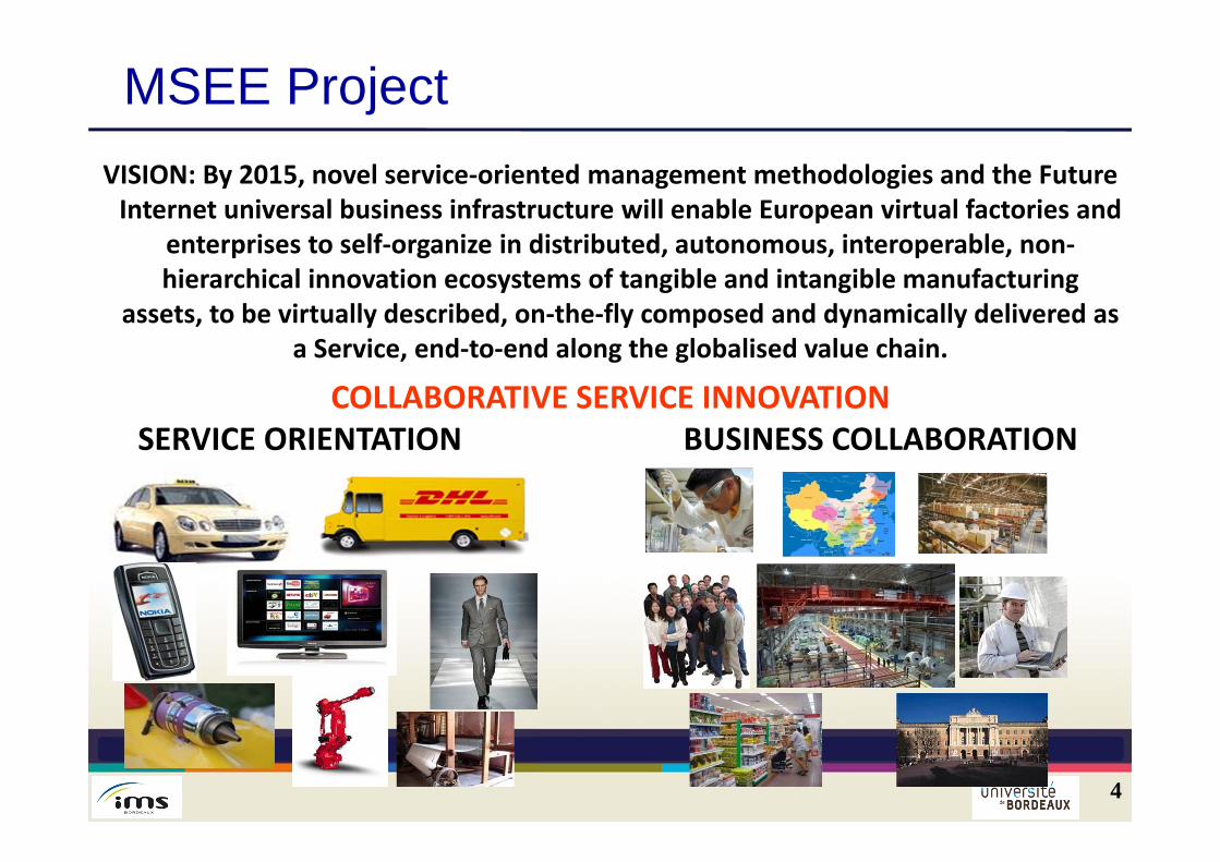
VISION: By 2015, novel service‐oriented management methodologies and the Future Internet universal business infrastructure will enable European virtual factories and
enterprises to self‐organize in distributed, autonomous, interoperable, non‐hierarchical innovation ecosystems of tangible and intangible manufacturing
assets, to be virtually described, on‐the‐fly composed and dynamically delivered as a Service, end‐to‐end along the globalised value chain.
SERVICE ORIENTATION BUSINESS COLLABORATIONCOLLABORATIVE SERVICE INNOVATION
MSEE Project
5
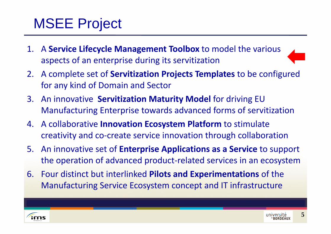
1. A Service Lifecycle Management Toolbox to model the various aspects of an enterprise during its servitization
2. A complete set of Servitization Projects Templates to be configured for any kind of Domain and Sector
3. An innovative Servitization Maturity Model for driving EU Manufacturing Enterprise towards advanced forms of servitization
4. A collaborative Innovation Ecosystem Platform to stimulate creativity and co‐create service innovation through collaboration
5. An innovative set of Enterprise Applications as a Service to support the operation of advanced product‐related services in an ecosystem
6. Four distinct but interlinked Pilots and Experimentations of the Manufacturing Service Ecosystem concept and IT infrastructure
Problem statement: servitisation European manufacturing enterprise willprogressively migrate from traditional product-centricbusiness to product-based service-oriented virtualenterprise and ecosystems The economy developed around the service relatedto concrete product is called PSS (Product ServiceSystem) or ServitisationA lot of definitions and characterisation have beendone for a service but few research works have beencarried out concerning the service system
6
Problem statement: servitisationIBM has characterised what is “service science”: agrowing multi-disciplinary research and academiceffort that integrates aspects of established fields likecomputer science, operations research, engineering,management sciences, business strategy, social andcognitive sciences, and legal sciences In the computer science domain, Service OrientedArchitectures (SOA), have revolutionized informationsystems, by providing software engineers withpowerful methodologies and tools for decomposingcomplex systems into autonomous components
7
Problem statement: servitisation
The servitization of manufacturing companies covers different levels of service provision and consequently different stages can be followed to evolve.In servitization, the product is considered as the coreelement of the service to deliver to customers andsubsequently we follow a manufacturing approach takinginto account the market pressure that oblige to create newmodels in order to meet the servitization challenge An appropriate concept to link products, product relatedservices and the needs of the users is the “ExtendedProduct”
8
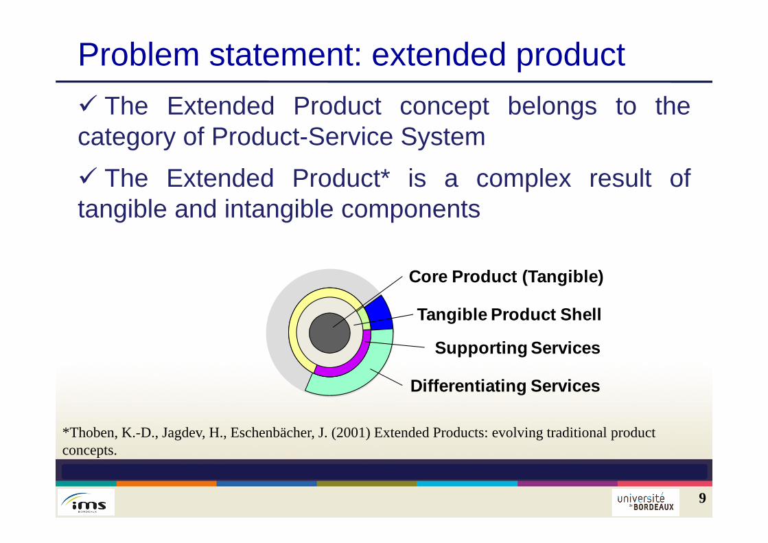
Problem statement: extended product The Extended Product concept belongs to thecategory of Product-Service System The Extended Product* is a complex result oftangible and intangible components
9
Supporting Services
Tangible Product Shell
Core Product (Tangible)
Differentiating Services
*Thoben, K.-D., Jagdev, H., Eschenbächer, J. (2001) Extended Products: evolving traditional product concepts.
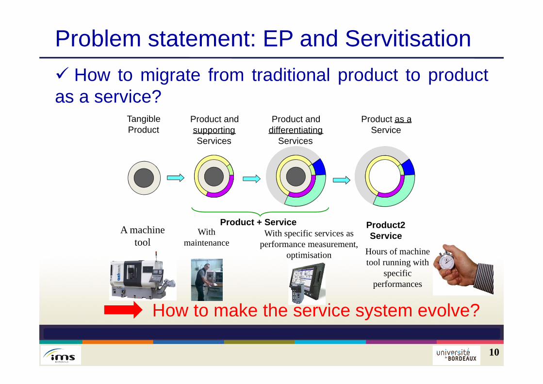
Problem statement: EP and Servitisation How to migrate from traditional product to productas a service?
10
A machine tool
Withmaintenance
With specific services as performance measurement,
optimisation Hours of machine tool running with
specificperformances
How to make the service system evolve?
TangibleProduct
Product + Service Product2Service
Product and supportingServices
Product and differentiating
Services
Product as aService
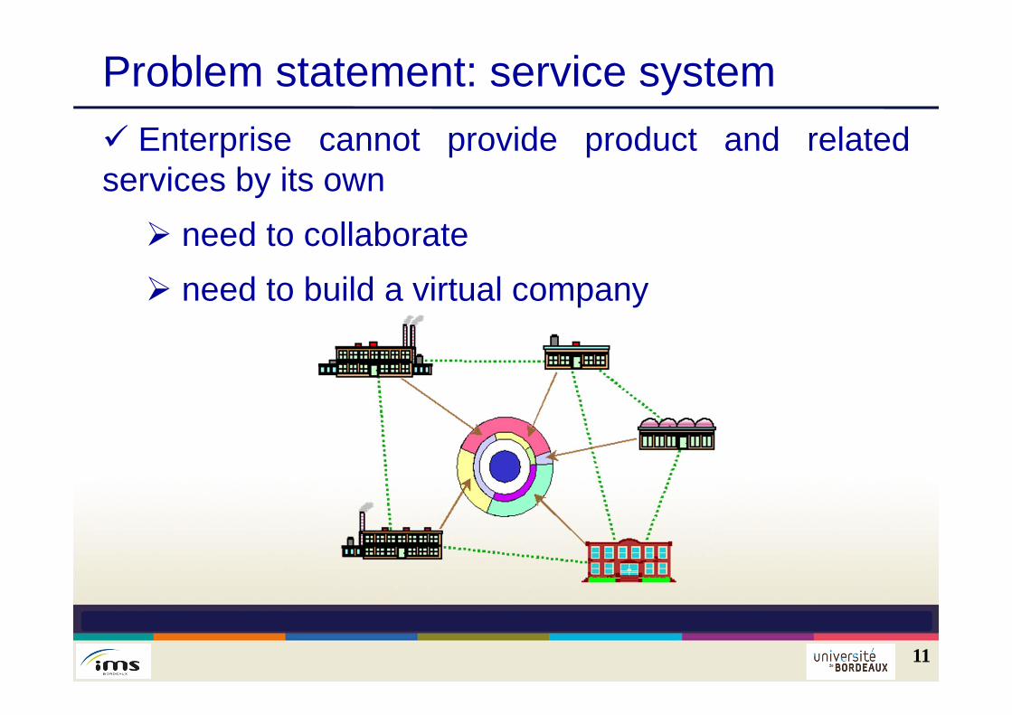
Problem statement: service system Enterprise cannot provide product and relatedservices by its own need to collaborate need to build a virtual company
11
Problem statement: service system But: the virtual enterprise can/should/must bedifferent according to the different phases of theservice life cycle Need to define the service life cycle phases Need to have a manufacturing and serviceecosystem need to ensure the interoperability betweenVME’s
12
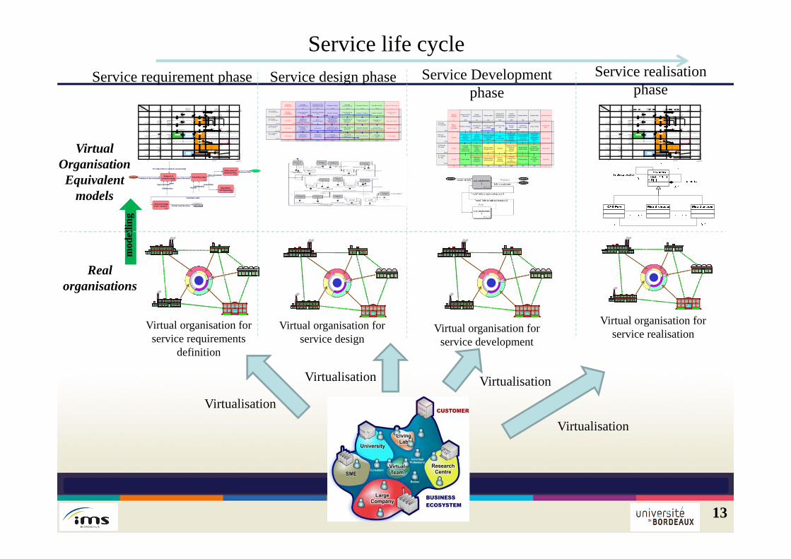
13
Service design phase Service Development phase
Service realisationphase
Service life cycle
Virtualisation
Virtualisation
Virtualisation
Virtual organisation for service design
Virtual organisation for service development
Virtual organisation for service realisation
Real organisations
VirtualOrganisationEquivalent
models
Managenon-compliance
(NC)
Manufacturingstrategy Delivery Strategy Quality strategy
Managingresources: Real
allocation
ManagementReview
manage inventoryand carriers
Manage resources:Projectedallocation
Manage finishedproduct inventory
Manufacturingequipmentinvestment.Training.
Customerrelationship quality
Planning Delivery Daily reportCustomer
Weekly reportCustomer
Quarterly reportCustomer
Activity interimreport
Market - Available
Technologies
Short-termplanning
(scheduling)
Managenon-compliance
(NC)
Short-termintervention(emergency)
Industrial strategicplan
Industrialequipmentinvestment.
Industrial Training
Manufacturingmethod . Validate
documents
WorkloadCustomer / SC
relationship quality.Release orders
MPS Annual Budget
Content QMSDeadline for
implementation.Management
Review
Quality strategyIndustrializationstrategy
IISC2EI SC2 SC2 SC3 SC3 SC3
Internal Information
II
Manageindustrialization
SC2
Externalinformation
EI
30-OP
H = 6 moisP = 1 semaine
20-TA
H = 1 anP = 3 mois
10-ST
H = 5 ansP = 6 mois
Manage overallcoordination andsynchronization
SC2
Manage Quality
SC2
40-OP
H = 2 semainesP = 1 jour
Manage Quality
SC3
Manage deliveries
SC3
ManageManufacturing
SC3
H=5 yearsP= 6 months
H=1 yearP= 3 months
H=6 monthsP= 1 week
H= 2 weeksP= 1 day
mod
ellin
g
Daily reportCustomer
Weekly reportCustomer
Quarterly reportCustomer
Activity interimreport
Market - Available
Technologies
Managingresources short
term Real allocation
Planning DeliveryManage
non-compliance(NC)
Short-termintervention(emergency)
Order TrackingShort-term
planning(scheduling)
Downstreamlogistics strategy
Workload
MPS Annual Budget
Industrial strategicplan
Manage inventoryReviving suppliers
Acceptingcommand
Revision of theprovisional plan
Choose answ er callfor tenders.
Negotiate offersOrder book
Forecast sales plan
Industrialequipmentinvestment.
Industrial Training
Manufacturingmethod . Validate
documents
Manage resourcesthrough term
Projectedallocation
Ordering suppliesManage the stock
Manage finishedproduct inventory
Customerrelationship quality.
Release orders
Volume of finishedproduct inventory
Frameworkcontract carriers
Manufacturingequipmentinvestment.
Training.Recruitment
Selecting suppliersControl critical
supplies
Content QMSDeadline for
implementation.Management
Review
Quality strategyUpstream logisticsstrategy
Resourcesstrategy
IndustrializationstrategyBusiness Strategy
IIMMRMIMCREI MS MD GQMCS
Internal Information
II
Manage manufacturing
(resources)
MMR
Manageindustrialization
MI
Manage customerrelationship
MCR
Externalinformation
EI
30-OP
H = 6 moisP = 1 semaine
20-TA
H = 1 anP = 3 mois
10-ST
H = 5 ansP = 6 mois
Manage supplies
MS
Manage deliveries
MD
Manage Quality
GQ
40-OP
H = 2 semainesP = 1 jour
Manage overallcoordination andsynchronization
MCS
H=5 yearsP= 6 months
H=1 yearP= 3 months
H=6 monthsP= 1 week
H= 2 weeksP= 1 day
INFORM. EXTERNES
H = 5 ans P = 1 an
H = 21 mois P = 6 mois
H = 12 m P = 3 m
H = 6 mois P = 2 sem.
INFOS INTERNES
H = 2 s à 1m P = 1 j à 1 s
H = 2,5 mois P = 1 jour
GERER LA CONCEPTION
GERER LES PRODUITS PLANIFIER
GERER LES RESSOURCES GERER LA
MAINTENANCEAPPROSACHATS Hum.Techn.
H = 2 jours P = 1 jour
T.R.
PLAN STRATEGIQUE
P.L.T.
BUDGET
P.M.T.
P.C.T.
CALCUL BESOINS
NETS
ACHATS
PROGRAMME ACHATS
PREVISIONS BUDGET
-MARCHES-
PREVOIR MARCHES
PLAN LT PRODUITS
FINIS
ESTIMER LES
BESOINS
CONCEPTION MACRO -GAMMES - NOMENC. PAR GTF
Prévisions commerciales
par GTF
Spécif. client
(maquette)
CONCEPTION . GAMME
. NOMENC . SPECIF.
PAR PRODUIT
Commandes comm.
- fermes - anticipées
Autorisations
PREVISIONS ESSAIS
Sorties stocks
Lancement
fabrication
Affect. prévision.
Prévisons maintenance
Plan annuel invest.
Plan inv. stratég.
Stratégie ressourc. humaines
Plan maintenance
préventive
Suivi réalisation O.E.
Suivi présences
màj stocks MP / PI
P.E.A.
Affect. perso.
Adaptation emploi
maind'œuvre
P.E.A.
Customer
Bivolino
Problem of the customer
To collect info to create N. service (obj)
demo
Idea of Services
PartnerKW Bivolino
Infos on solution
proposition
Product and Services
KW Bivolino
Business Plan
mpl.Phase
Customer order
input customer
Analysis ofcustomer needs
ACNFeasibility study
FS
Negotiation and Agreement
NA
Technical designof the "solution"
TDS
Elaboration ofBusiness Plan
Proc
INFORM. EXTERNES
H = 5 ans P = 1 an
H = 21 mois P = 6 mois
H = 12 m P = 3 m
H = 6 mois P = 2 sem.
INFOS INTERNES
H = 2 s à 1m P = 1 j à 1 s
H = 2,5 mois P = 1 jour
GERER LA CONCEPTION
GERER LES PRODUITS PLANIFIER
GERER LES RESSOURCES GERER LA
MAINTENANCEAPPROSACHATS Hum.Techn.
H = 2 jours P = 1 jour
T.R.
PLAN STRATEGIQUE
P.L.T.
BUDGET
P.M.T.
P.C.T.
CALCUL BESOINS
NETS
ACHATS
PROGRAMME ACHATS
PREVISIONS BUDGET
-MARCHES-
PREVOIR MARCHES
PLAN LT PRODUITS
FINIS
ESTIMER LES
BESOINS
CONCEPTION MACRO -GAMMES - NOMENC. PAR GTF
Prévisions commerciales
par GTF
Spécif. client
(maquette)
CONCEPTION . GAMME
. NOMENC . SPECIF.
PAR PRODUIT
Commandes comm.
- fermes - anticipées
Autorisations
PREVISIONS ESSAIS
Sorties stocks
Lancement
fabrication
Affect. prévision.
Prévisons maintenance
Plan annuel invest.
Plan inv. stratég.
Stratégie ressourc. humaines
Plan maintenance
préventive
Suivi réalisation O.E.
Suivi présences
màj stocks MP / PI
P.E.A.
Affect. perso.
Adaptation emploi
maind'œuvre
P.E.A.
Service requirement phase
Virtual organisation for service requirements
definition
Virtualisation
14
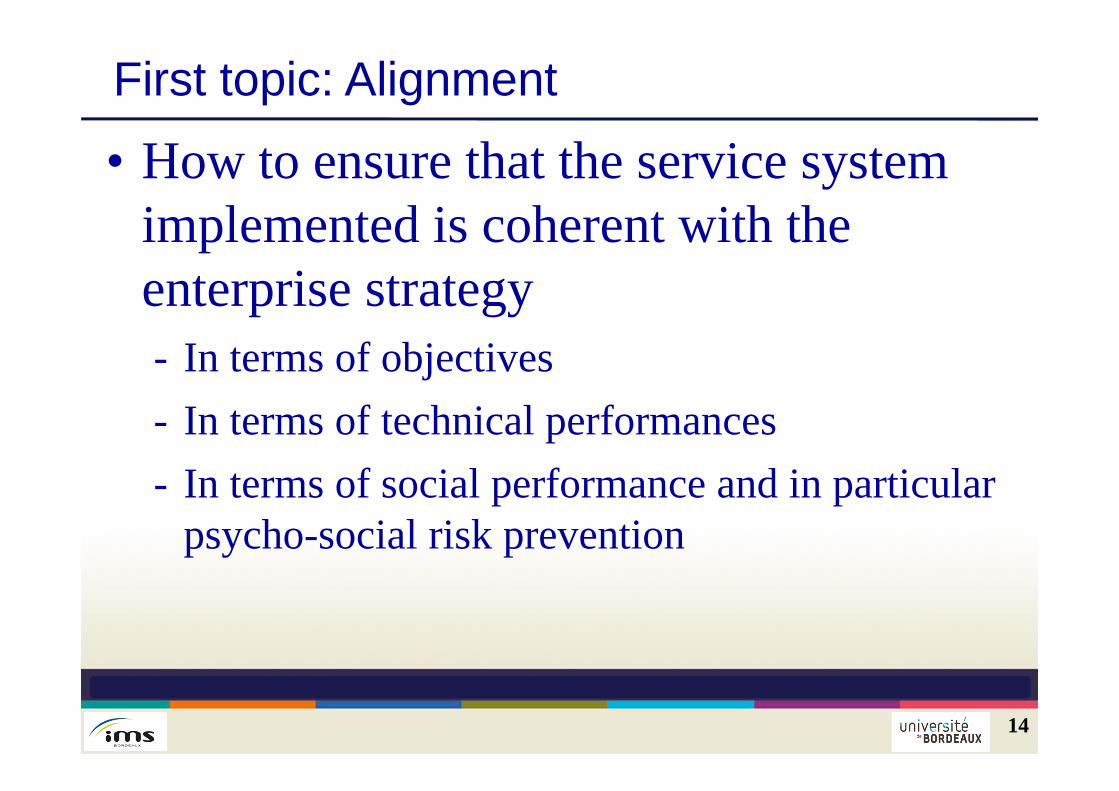
First topic: Alignment
• How to ensure that the service system implemented is coherent with the enterprise strategy- In terms of objectives- In terms of technical performances- In terms of social performance and in particular
psycho-social risk prevention
15
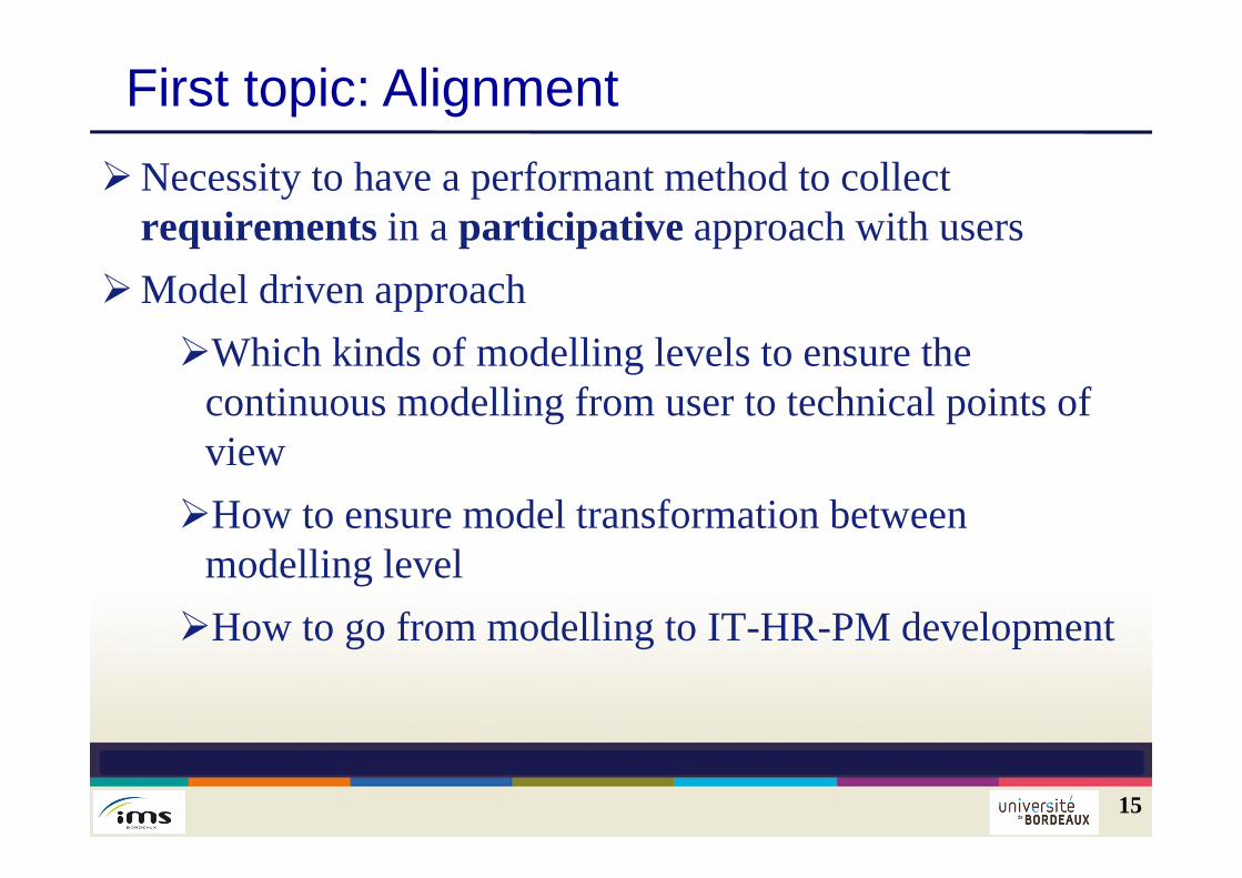
First topic: AlignmentNecessity to have a performant method to collect
requirements in a participative approach with usersModel driven approach
Which kinds of modelling levels to ensure the continuous modelling from user to technical points of viewHow to ensure model transformation between
modelling levelHow to go from modelling to IT-HR-PM development
16
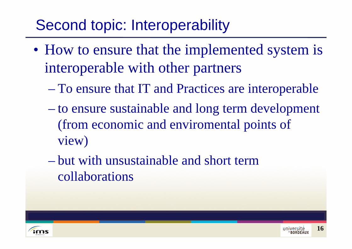
Second topic: Interoperability• How to ensure that the implemented system is
interoperable with other partners– To ensure that IT and Practices are interoperable– to ensure sustainable and long term development
(from economic and enviromental points of view)
– but with unsustainable and short termcollaborations
17
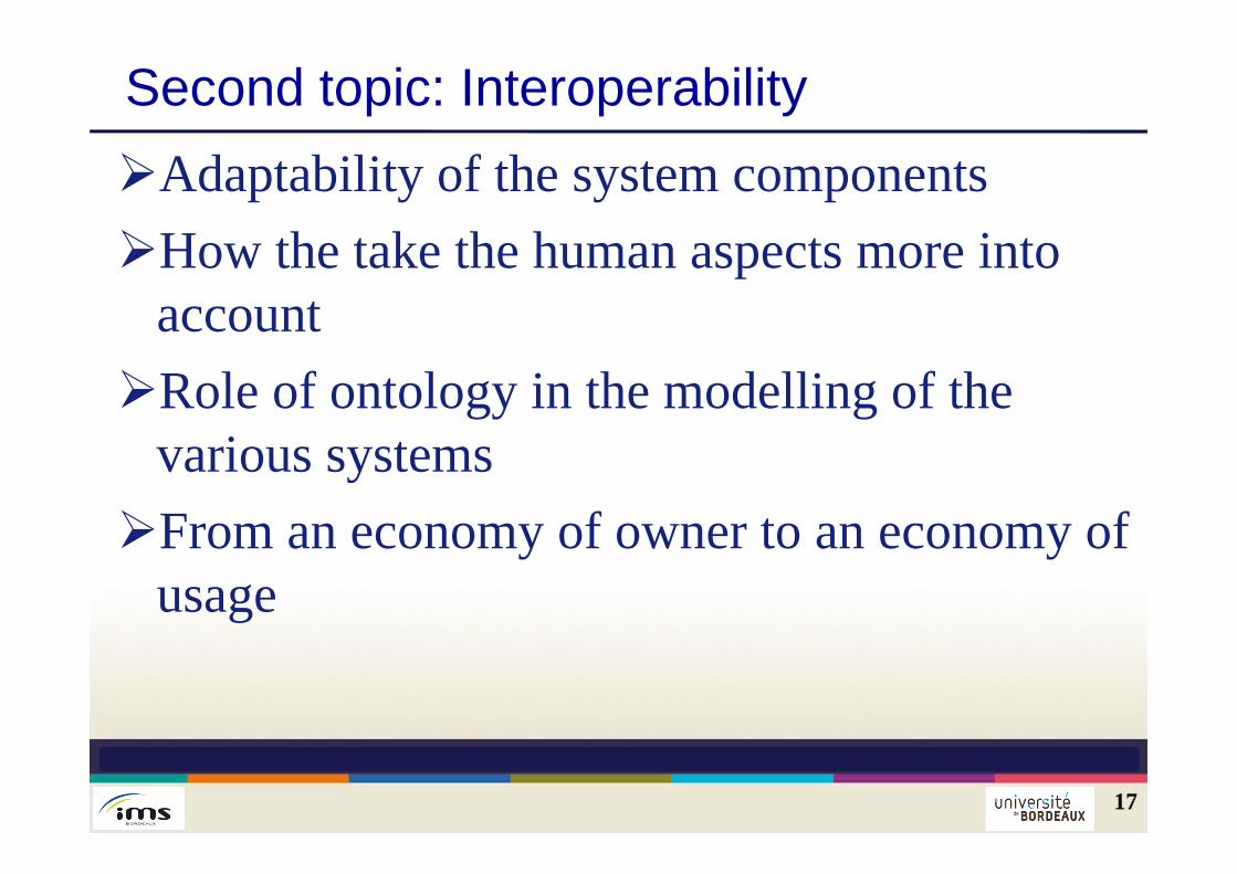
Second topic: InteroperabilityAdaptability of the system componentsHow the take the human aspects more into
accountRole of ontology in the modelling of the
various systemsFrom an economy of owner to an economy of
usage
How to ensure interoperability: Service system modelling
Need to understand why and how the virtualenterprises will be organised Need to be sure that the organisation andcomponents of the virtual enterprise will be coherentwith the objectives of the VE need to use enterprise modelling but not todevelop a new language need to have a progressive approach in themodelling from the business definition to thedetailed implementation
18
Why a Model Driven Approach To start from the users points of view (businesslevel) To separate and share the preoccupations fromusers to technique To have a set of coherent modelling levels which
are based on system theory Finally to facilitate the alignment between the
business view and the technical development At each level, to validate more and more detailed
specifications until the implementation
19
Background in Model Driven Approach
20
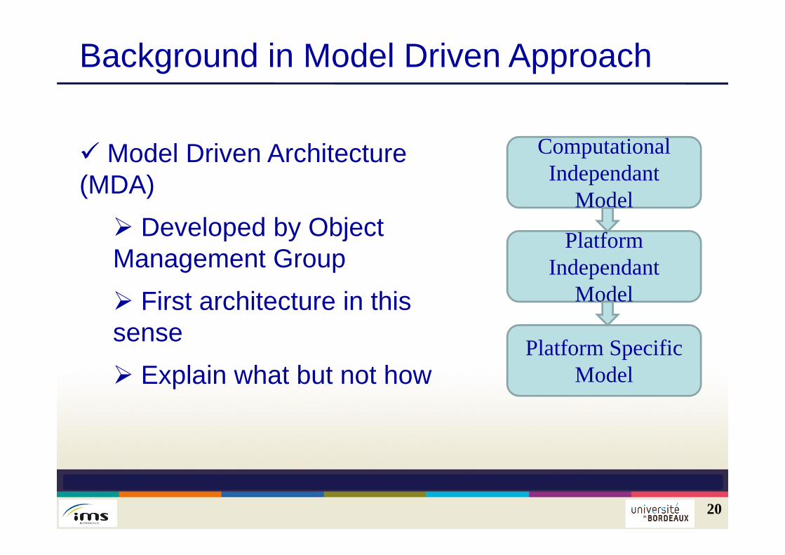
Model Driven Architecture (MDA) Developed by Object Management Group First architecture in this sense Explain what but not how
ComputationalIndependant
Model
Platform Independant
Model
Platform SpecificModel
21
Background in Model Driven Approach
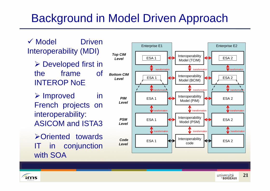
Model DrivenInteroperability (MDI)
Developed first inthe frame ofINTEROP NoE
Improved inFrench projects oninteroperability:ASICOM and ISTA3
Oriented towardsIT in conjunctionwith SOA
Enterprise E2Enterprise E1
ESA 1 ESA 2InteroperabilityModel (PIM)
PIM Level
PSM Level
ESA 1 ESA 2InteroperabilityModel (PSM)
CodeLevel
ESA 1 ESA 2Interoperabilitycode
InteroperabilityModel (BCIM)
Bottom CIMLevel
transformation
transformation
transformation
transformation
transformation
transformation
ESA 1 ESA 2InteroperabilityModel (TCIM)
Top CIMLevel
transformation
transformation
transformation
ESA 1 ESA 2
transformation
transformationtransformation
MDSEA
22
The proposed Model Driven Service EngineeringArchitecture is elaborated based:
On MDA and MDI
On several modelling levels
MDSEA must be adapted to services systems: toimplement in VME IT, Organisation and Physical means
MDSEA must define which kinds of modelling languageswill be used
MDSEA must define the transformation mechanisms
23
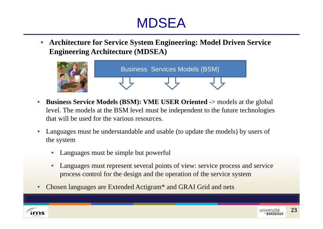
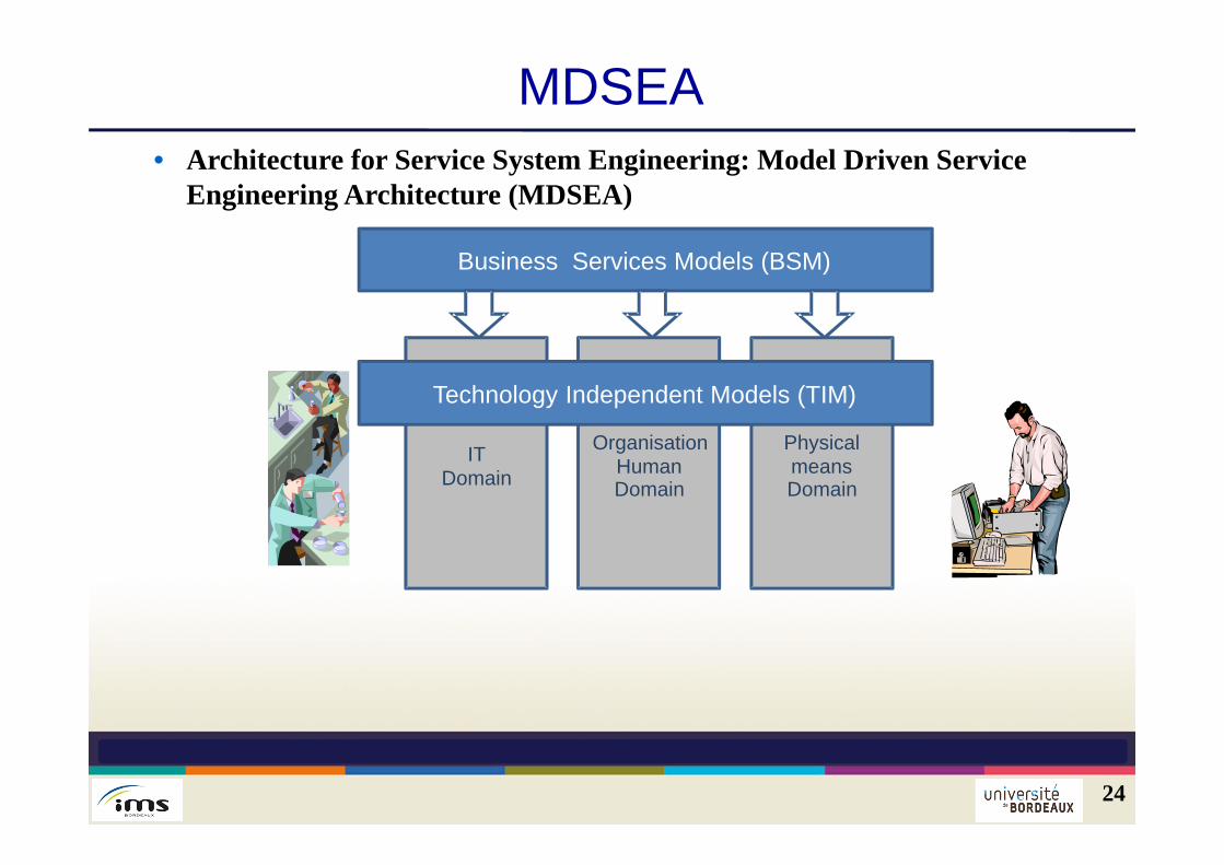
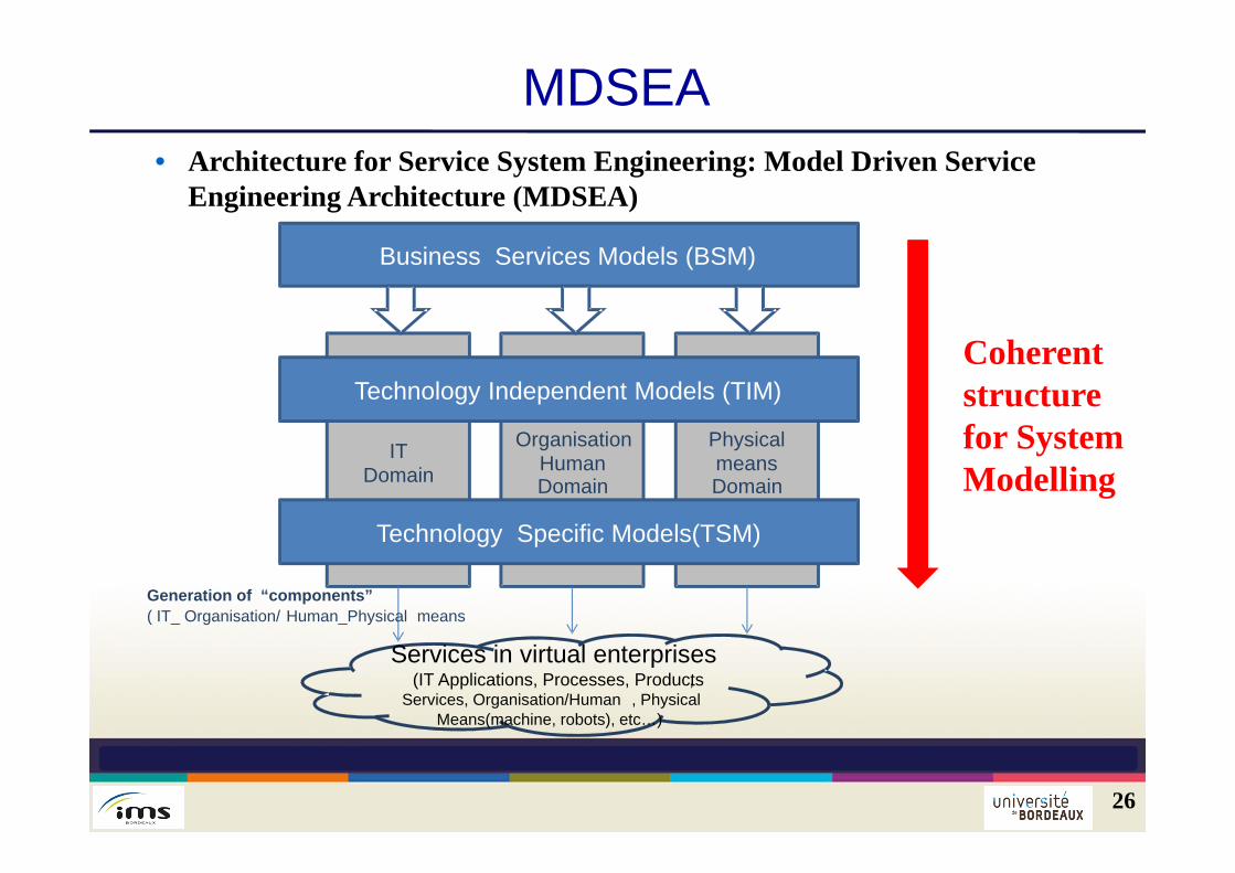
MDSEA• Architecture for Service System Engineering: Model Driven Service
Engineering Architecture (MDSEA)
Business Services Models (BSM)
• Business Service Models (BSM): VME USER Oriented -> models at the global level. The models at the BSM level must be independent to the future technologies that will be used for the various resources.
• Languages must be understandable and usable (to update the models) by users of the system
• Languages must be simple but powerful
• Languages must represent several points of view: service process and service process control for the design and the operation of the service system
• Chosen languages are Extended Actigram* and GRAI Grid and nets
24
MDSEA• Architecture for Service System Engineering: Model Driven Service
Engineering Architecture (MDSEA)
Business Services Models (BSM)
OrganisationHumanDomain
Physical meansDomain
IT Domain
Technology Independent Models (TIM)
25
MDSEA
• Technology Independent Models (TIM): First technical level : The models at the TIM level must provide sufficient details to allow developing or buying software applications, components, recruiting human operators / managers or establishing internal training plans, buying and realizing machine devices, for supporting and delivering services in interaction with customers.
• Chosen languages are BPMN 2.0 and UML class diagrams
26
MDSEA• Architecture for Service System Engineering: Model Driven Service
Engineering Architecture (MDSEA)
Coherent structure for System Modelling
OrganisationHumanDomain
Physical meansDomain
IT Domain
Technology Independent Models (TIM)
Business Services Models (BSM)
Technology Specific Models(TSM)
Services in virtual enterprises(IT Applications, Processes, Products,
Services, Organisation/Human , Physical Means(machine, robots), etc…)
Generation of “components”( IT_ Organisation/ Human_Physical means
Business Service Modelling level Business Service is the first level of modelling Global description of the virtual enterprise Independent to the future technologies of resources Can be decomposed into 2 sub levels top BSM: global bottom BSM: domain concerns by theservitisation
27
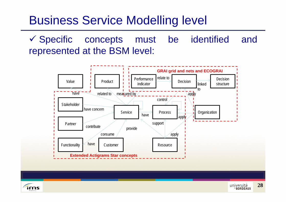
Business Service Modelling level Specific concepts must be identified andrepresented at the BSM level:
28
ResourceFunctionality
Stakeholder
DecisionPerformanceindicatorProductValue
provide
measured byrelated tohavecontrol
relate to
have concern
apply
Customer
consume
Partner contribute
have Organization
Decisionstructurelinked
to
applyService Process
have
apply
Extended Actigrams Star concepts
GRAI grid and nets and ECOGRAI
support
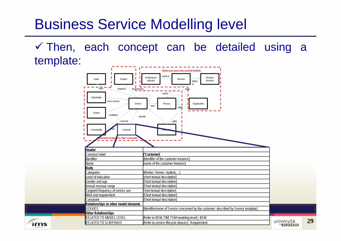
Business Service Modelling level Then, each concept can be detailed using atemplate:
29
ResourceFunctionality
Stakeholder
DecisionPerformanceindicatorProductValue
provide
measured byrelated tohave
control
relate to
have concern
apply
Customer
consume
Partnercontribute
haveOrganization
Decisionstructurelinked
to
applyService Process
have
apply
Extended Actigrams Star concepts
GRAI grid and nets and ECOGRAI
HeaderConstruct label [‘Customer]Identifier [Identifier of the customer instance]Name [name of the customer instance]BodyCategories [Worker, farmer, student,…]Level of education [short textual description]Gender and age [Short textual description]Annual revenue range [Short textual description]Targeted frequency of service use Short textual description]Wish and requirement [Short textual description]Constraint [Short textual description]Relationships to other model elementsSERVICE [Identifier/name of Service concerned by the customer: described by Service template]Other RelationshipsRELATED TO MODEL LEVEL [Refer to BSM, TIM, TSM modeling level] : BSMRELATED TO SLM PHASE [Refer to service lifecycle phases] : Requirement
30
MDSEA
Managenon-compliance
(NC)
Manufacturingstrategy Delivery Strategy Quality strategy
Managingresources: Real
allocation
ManagementReview
manage inventoryand carriers
Manage resources:Projectedallocation
Manage finishedproduct inventory
Manufacturingequipmentinvestment.Training.
Customerrelationship quality
Planning Delivery Daily reportCustomer
Weekly reportCustomer
Quarterly reportCustomer
Activity interimreport
Market - Available
Technologies
Short-termplanning
(scheduling)
Managenon-compliance
(NC)
Short-termintervention(emergency)
Industrial strategicplan
Industrialequipmentinvestment.
Industrial Training
Manufacturingmethod . Validate
documents
WorkloadCustomer / SC
relationship quality.Release orders
MPS Annual Budget
Content QMSDeadline for
implementation.Management
Review
Quality strategyIndustrializationstrategy
IISC2EI SC2 SC2 SC3 SC3 SC3
Internal Information
II
Manageindustrialization
SC2
Externalinformation
EI
30-OP
H = 6 moisP = 1 semaine
20-TA
H = 1 anP = 3 mois
10-ST
H = 5 ansP = 6 mois
Manage overallcoordination andsynchronization
SC2
Manage Quality
SC2
40-OP
H = 2 semainesP = 1 jour
Manage Quality
SC3
Manage deliveries
SC3
ManageManufacturing
SC3
H=5 yearsP= 6 months
H=1 yearP= 3 months
H=6 monthsP= 1 week
H= 2 weeksP= 1 day
Customer
Bivolino
Problem of the customer
To collect info to create N. service (obj)
demo
Idea of Services
PartnerKW Bivolino
Infos on solution
proposition
Product and Services
KW Bivolino
Business Plan
mpl.Phase
Customer order
input customer
Analysis ofcustomer needs
ACNFeasibility study
FS
Negotiation and Agreement
NA
Technical designof the "solution"
TDS
Elaboration ofBusiness Plan
Proc
INFORM.
EXTERNES
H = 5 ans
P = 1 an
H = 21 mois
P = 6 mois
H = 12 m
P = 3 m
H = 6 mois
P = 2 sem.
INFOS
INTERNES
H = 2 s à 1m
P = 1 j à 1 s
H = 2,5 mois
P = 1 jour
GERER LA
CONCEPTION
GERER LES
PRODUITS PLANIFIER
GERER LES
RESSOURCES GERER LA
MAINTENANCE
APPROSACHATS Hum.Techn.
H = 2 jours
P = 1 jour
T.R.
PLAN
STRATEGIQUE
P.L.T.
BUDGET
P.M.T.
P.C.T.
CALCUL
BESOINS
NETS
ACHATS
PROGRAMME
ACHATS
PREVISIONS
BUDGET
-MARCHES-
PREVOIR
MARCHES
PLAN LT
PRODUITS
FINIS
ESTIMER
LES
BESOINS
CONCEPTION
MACRO
-GAMMES
- NOMENC.
PAR GTF
Prévisions
commerciales
par GTF
Spécif.
client
(maquette)
CONCEPTION
. GAMME
. NOMENC
. SPECIF.
PAR PRODUIT
Commandes
comm.
- fermes
- anticipées
Autorisations
PREVISIONS
ESSAIS
Sorties
stocks
Lancement
fabrication
Affect.
prévision.
Prévisons
maintenance
Plan
annuel
invest.
Plan inv.
stratég.
Stratégie
ressourc.
humaines
Plan
maintenance
préventive
Suivi
réalisation O.E.
Suivi
présences
màj stocks
MP / PI
P.E.A.
Affect.
perso.
Adaptation
emploi
maind'œuvre
P.E.A.
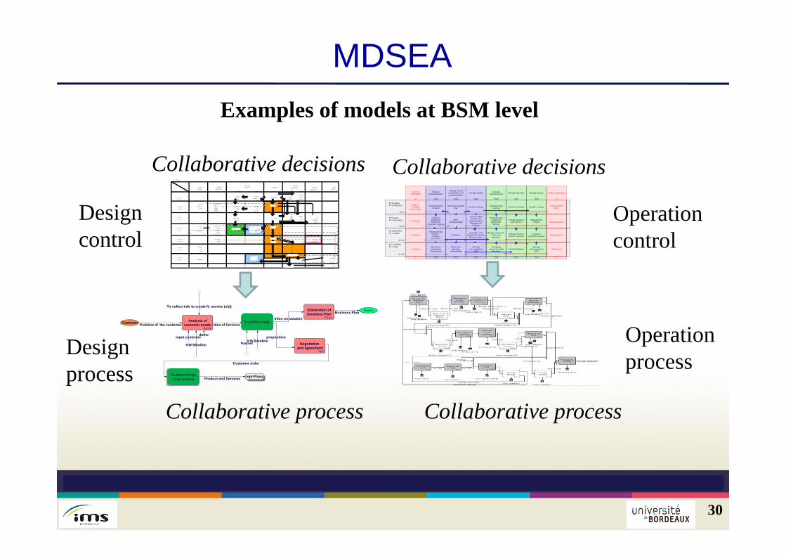
Design process
Design control
Operationprocess
Operationcontrol
Feasibility study
Technical design of the solution
Collaborative decisions Collaborative decisions
Collaborative process Collaborative process
Examples of models at BSM level
Technology Independent Modelling level Second level of abstraction in the representation ofthe service system Gives detailed specifications of the structure andfunctionalities of the service system but not proposetechnological details the resources specifications are described for IT organisation/human physical means
31
Technology Independent Modelling level The functionalities are derived from BSM models Complementary data can be useful to collect the functionalities can be classified by importancein order to serve the selection of resources at thelower level the functionalities are also covering theinteroperability problems to be connected to othercompanies of the virtual enterprise or to othercompanies of the ecosystem
32
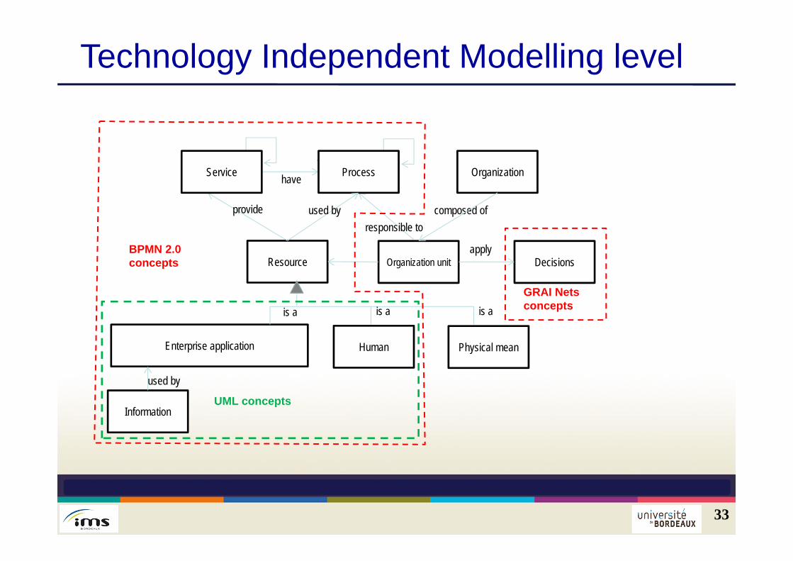
Technology Independent Modelling level
33
Resource
provide composed of
have Organization
is a
Enterprise application Physical meanHuman
Information
used by
is a is a
Organization unit
responsible to
Service Process
BPMN 2.0 concepts
used by
Decisionsapply
UML concepts
GRAI Nets concepts
Technology Specific Modelling level Details how the system will use each resource To choose how to buy or to develop and IT
solution To choose a human resources and to define
him/her role and place in the organisation To select a specific machine and to describe its
performance
34
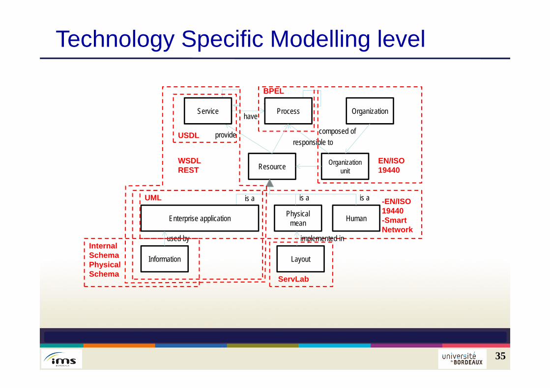
Technology Specific Modelling level
35
Resource
provide composed of
have Organization
is a
Physical mean HumanEnterprise application
Information
used by
is a is a
Organization unit
responsible to
Service Process
-EN/ISO19440-SmartNetwork
EN/ISO19440
UML
BPEL
InternalSchemaPhysical Schema
WSDLREST
Layout
implemented in
USDL
ServLab
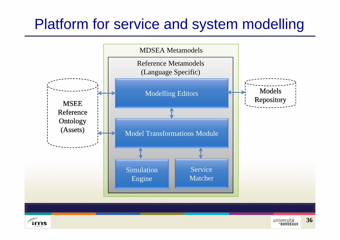
Platform for service and system modelling
36
MDSEA Metamodels
Reference Metamodels(Language Specific)
Modelling Editors
Model Transformations Module
MSEE Reference Ontology (Assets)
MSEE Reference Ontology (Assets)
Simulation Engine
Models Repository
Models Repository
Service Matcher
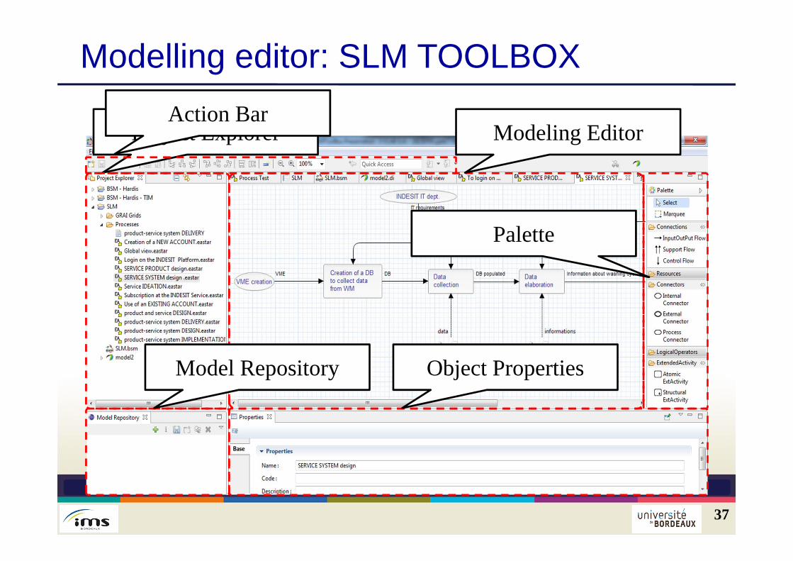
Modelling editor: SLM TOOLBOX
37
Project ExplorerAction Bar
Modeling Editor
Model Repository Object Properties
Palette
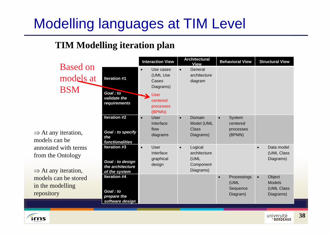
Modelling languages at TIM Level
38
TIM Modelling iteration planInteraction View Architectural
View Behavioral View Structural View
Iteration #1
Goal : to validate the requirements
Use cases (UML Use Cases Diagrams)
User centered processes (BPMN)
General architecture diagram
Iteration #2
Goal : to specify the functionalities
User Interface flow diagrams
Domain Model (UML Class Diagrams)
System centered processes (BPMN)
Iteration #3
Goal : to design the architecture of the system
User Interface graphical design
Logical architecture (UML Component Diagrams)
Data model (UML Class Diagrams)
Iteration #4
Goal : to prepare the software design
Processings (UML Sequence Diagram)
Object Models (UML Class Diagrams)
Based on models atBSM
At any iteration, models can be annotated with terms from the Ontology
At any iteration, models can be stored in the modellingrepository
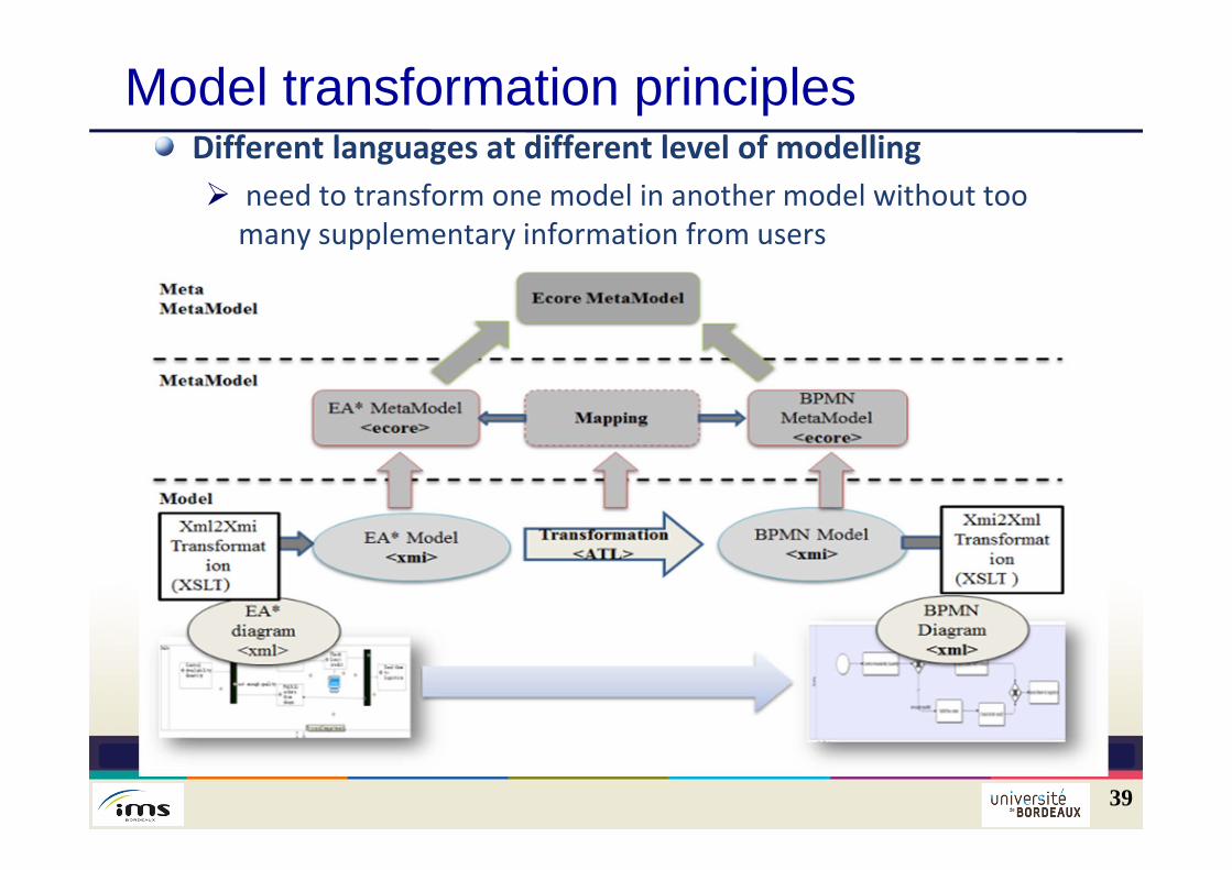
Model transformation principles
39
Different languages at different level of modelling need to transform one model in another model without too
many supplementary information from users
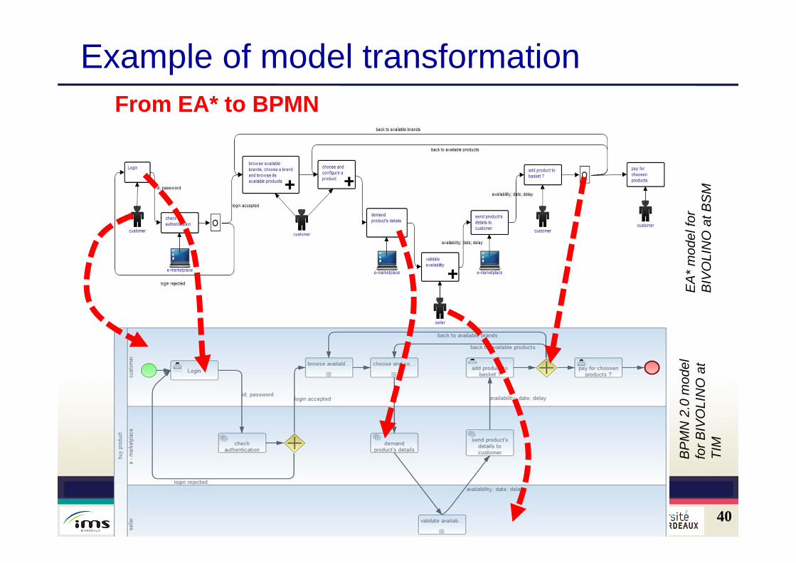
Example of model transformation
40
From EA* to BPMN
EA
* m
odel
for
BIV
OLI
NO
atB
SM
BP
MN
2.0
mod
el
for B
IVO
LIN
O a
tTI
M
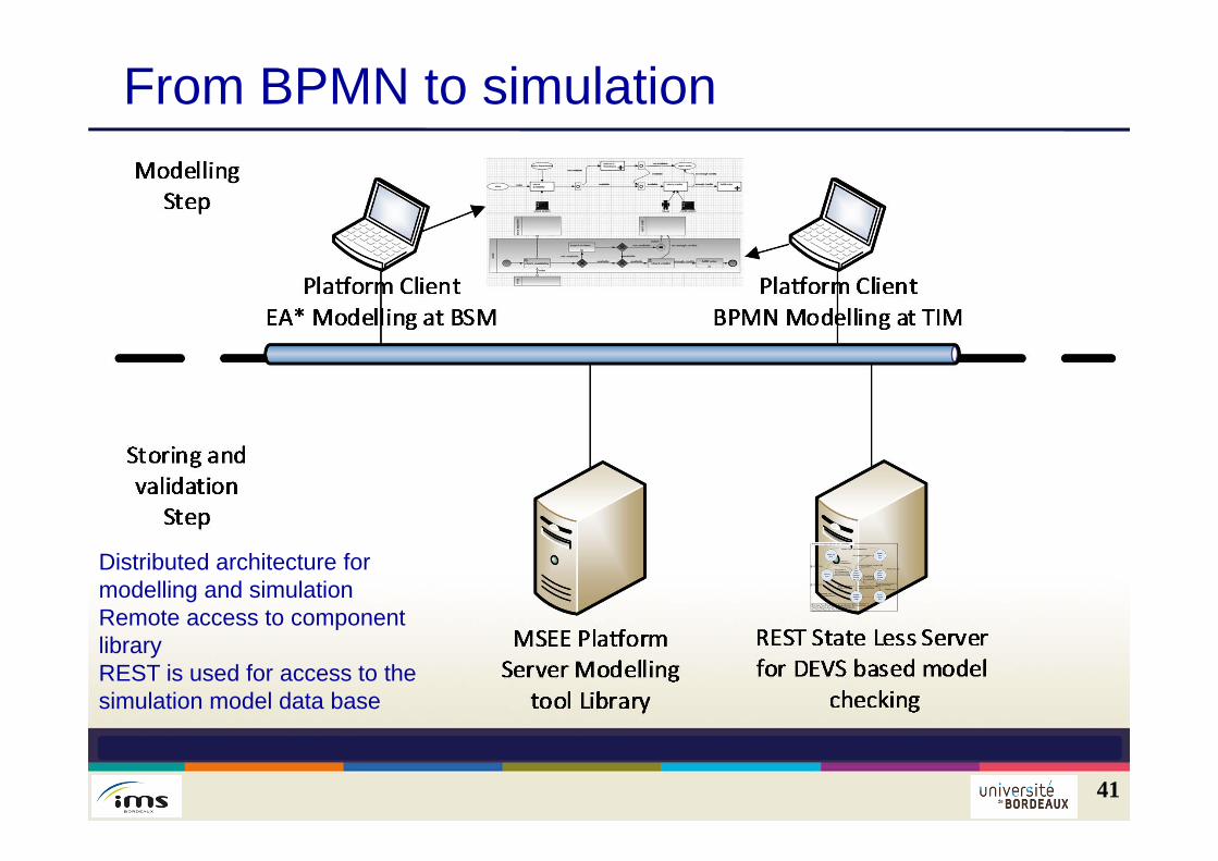
From BPMN to simulation
41
Distributed architecture for modelling and simulationRemote access to component libraryREST is used for access to the simulation model data base
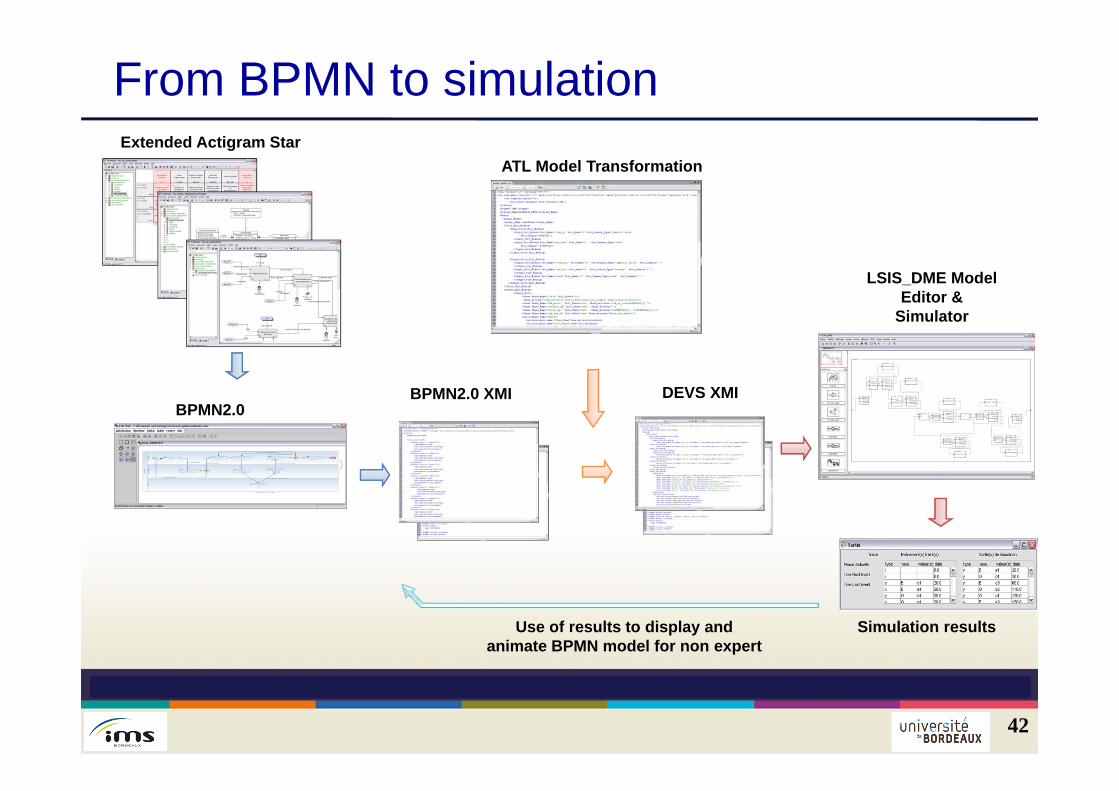
From BPMN to simulation
42
BPMN2.0 XMI
LSIS_DME Model Editor &
Simulator
DEVS
Simulation results
ATL Model Transformation
Use of results to display and animate BPMN model for non expert
DEVS XMIBPMN2.0
Extended Actigram Star
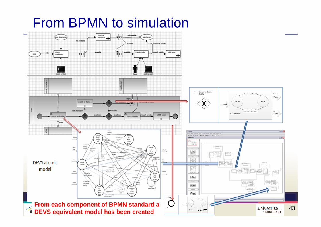
From BPMN to simulation
43
Exclusive Gateway
(XOR)
T : Durée de vie
T= ∞
Token
T = 0
£ :arrivée de l’entité
¥ : évaluer la condition Envoie vers la sortie
Token
Token
Out 0
Out 1
End
From each component of BPMN standard a DEVS equivalent model has been created
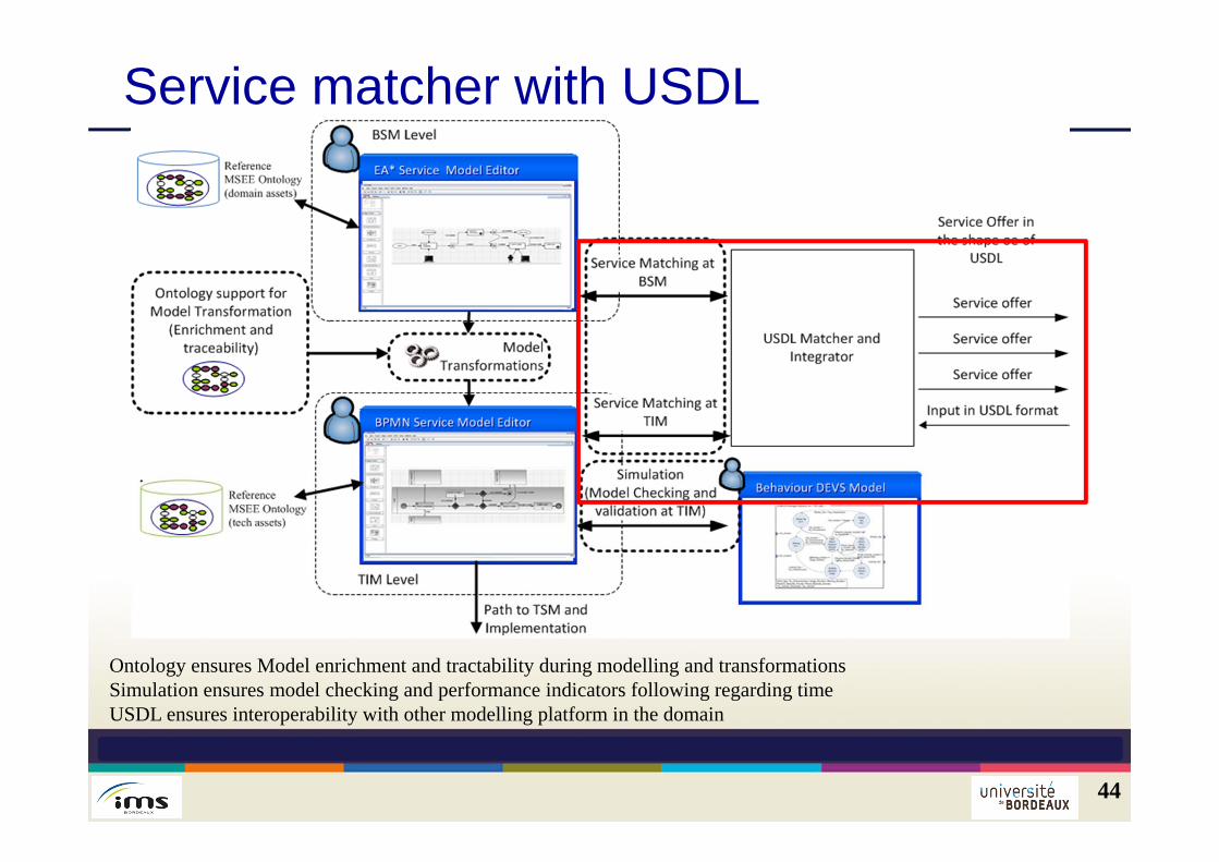
Service matcher with USDL
44
Ontology ensures Model enrichment and tractability during modelling and transformationsSimulation ensures model checking and performance indicators following regarding time USDL ensures interoperability with other modelling platform in the domain
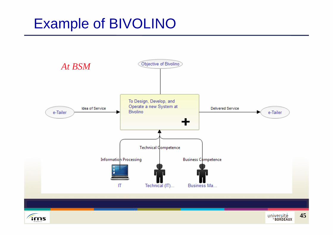
Example of BIVOLINO
45
At BSM
Example of BIVOLINO
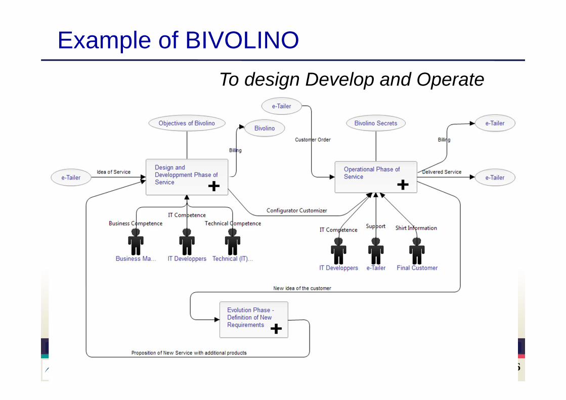
46
To design Develop and Operate
Example of BIVOLINO
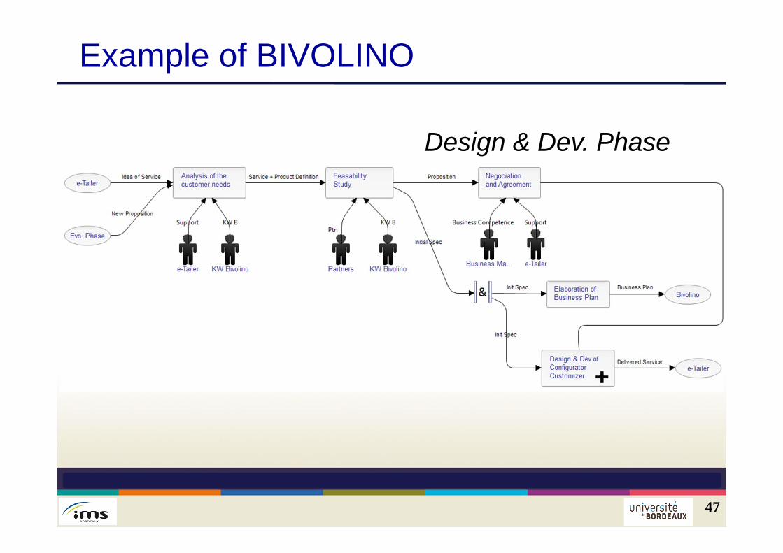
47
Design & Dev. Phase
Example of BIVOLINO
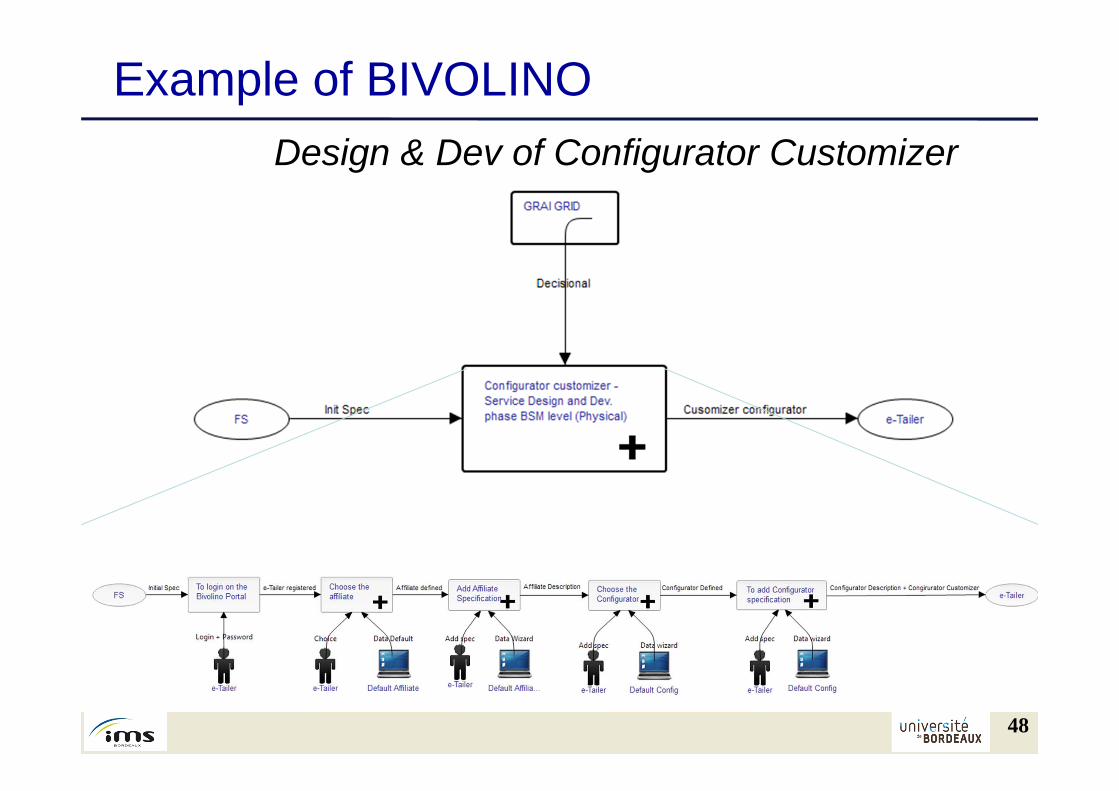
48
Design & Dev of Configurator Customizer
Example of BIVOLINO
49
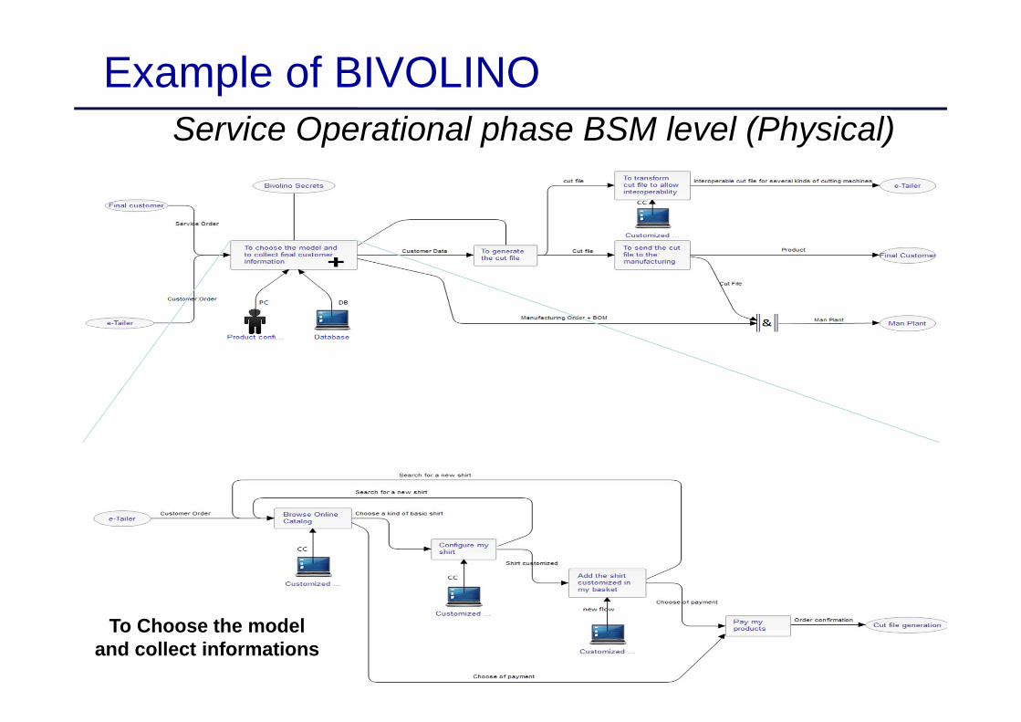
Service Operational phase BSM level (Physical)
To Choose the model and collect informations
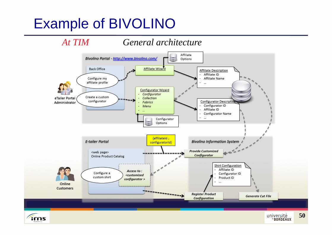
Example of BIVOLINO
50
At TIM General architecture
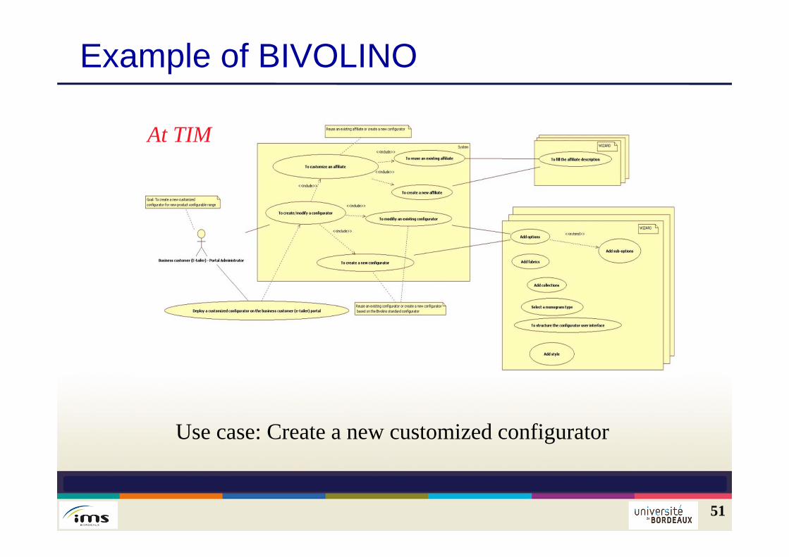
51
Use case: Create a new customized configurator
Example of BIVOLINO
At TIM
Example of BIVOLINO
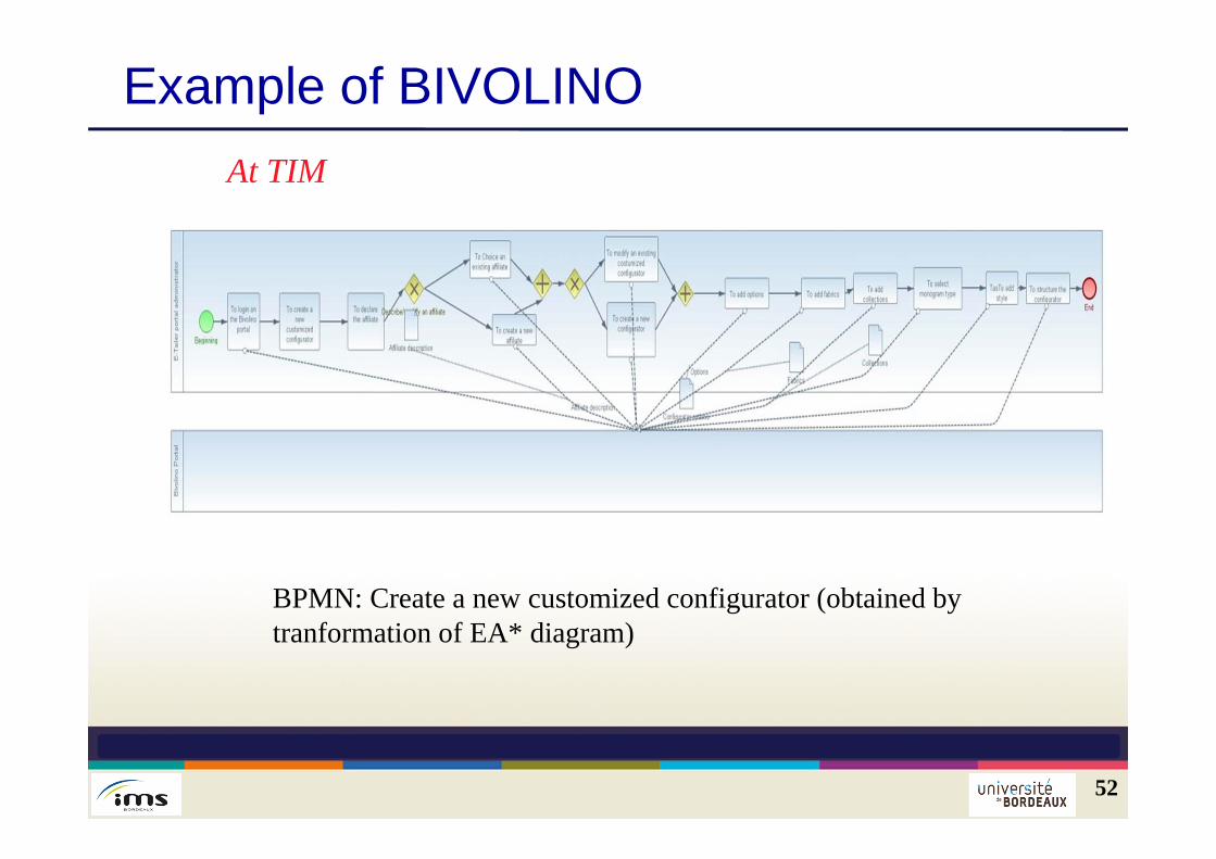
52
BPMN: Create a new customized configurator (obtained by tranformation of EA* diagram)
At TIM
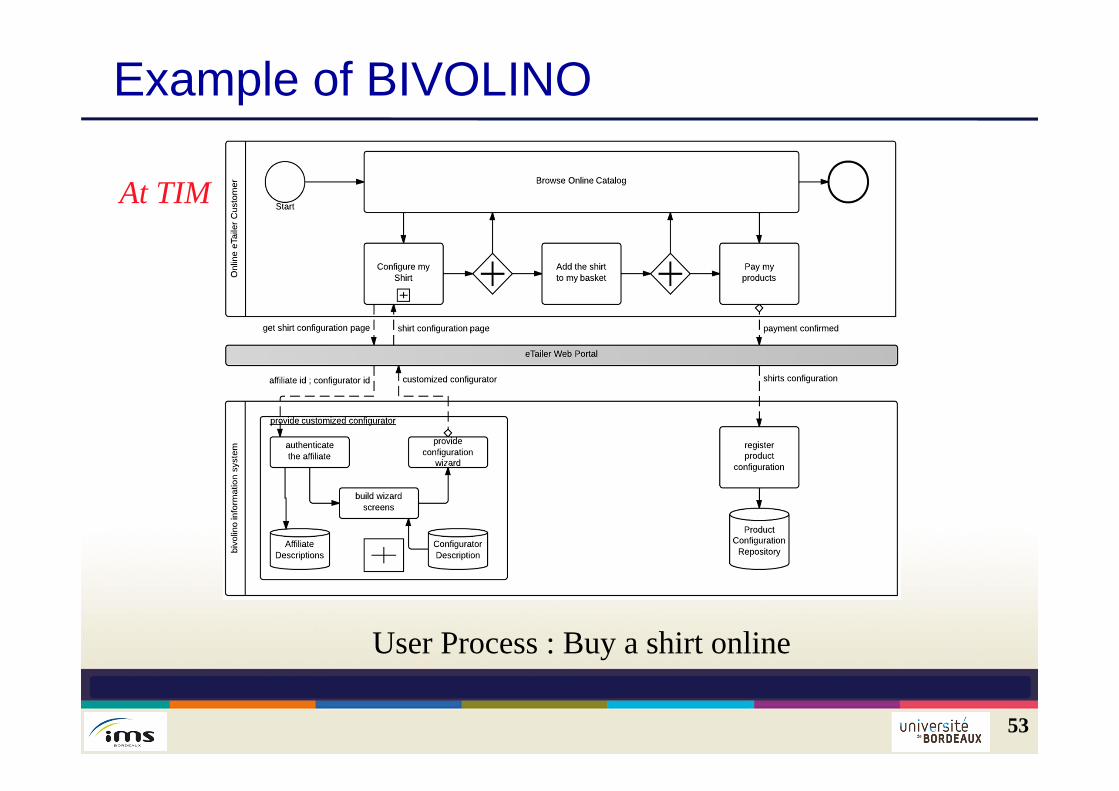
Example of BIVOLINO
53
User Process : Buy a shirt online
At TIM
First results for BIVOLINO
54
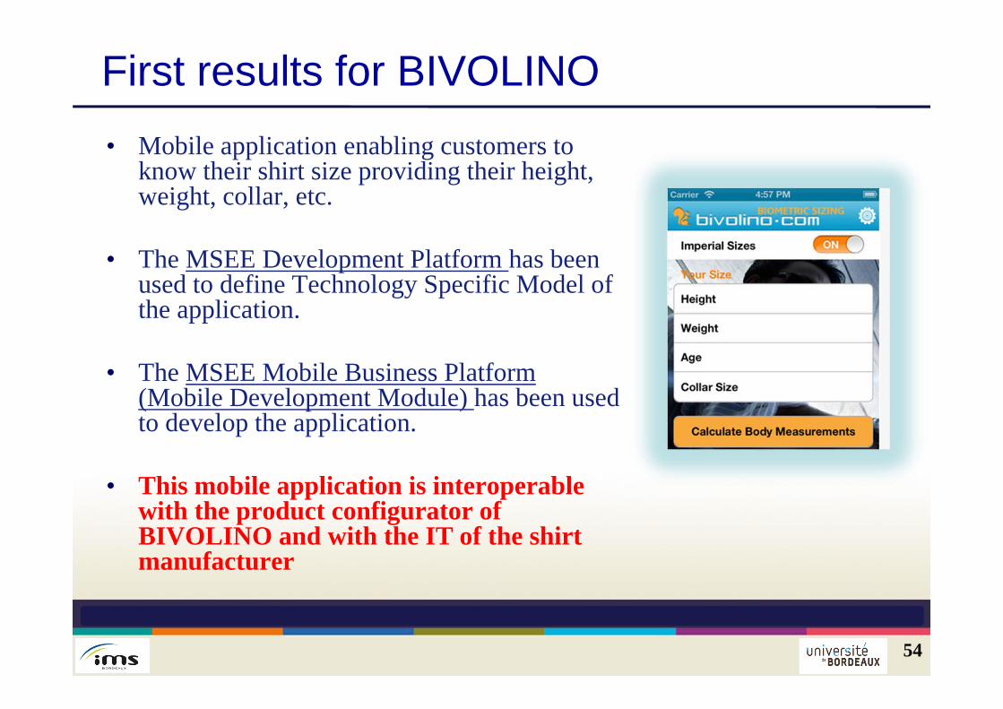
• Mobile application enabling customers to know their shirt size providing their height, weight, collar, etc.
• The MSEE Development Platform has been used to define Technology Specific Model of the application.
• The MSEE Mobile Business Platform (Mobile Development Module) has been used to develop the application.
• This mobile application is interoperable with the product configurator of BIVOLINO and with the IT of the shirt manufacturer
Conclusions
The use of enterprise modelling is crucial to understand therunning of a VE and to ensure that the implementation iscoherent with its strategic objectives and enables theinteroperability of practices and IT The representation must be done at several levels of detailin a coherent architecture in order to ensure the coherence ofthe modelling languages Need to apply the MDSEA principles and related languagesto validate and modify them Acknowledgement to
55