internet-draft tom herbert · internet-draft tom herbert intended status: informational facebook...
TRANSCRIPT

INTERNET-DRAFT Tom HerbertIntended Status: Informational FacebookExpires: April 30, 2017 October 27, 2016
Identifier-locator addressing for IPv6 draft-herbert-nvo3-ila-03
Abstract
This specification describes identifier-locator addressing (ILA) for IPv6. Identifier-locator addressing differentiates between location and identity of a network node. Part of an address expresses the immutable identity of the node, and another part indicates the location of the node which can be dynamic. Identifier-locator addressing can be used to efficiently implement overlay networks for network virtualization as well as solutions for use cases in mobility.
Status of this Memo
This Internet-Draft is submitted to IETF in full conformance with the provisions of BCP 78 and BCP 79.
Internet-Drafts are working documents of the Internet Engineering Task Force (IETF), its areas, and its working groups. Note that other groups may also distribute working documents as Internet-Drafts.
Internet-Drafts are draft documents valid for a maximum of six months and may be updated, replaced, or obsoleted by other documents at any time. It is inappropriate to use Internet-Drafts as reference material or to cite them other than as "work in progress."
The list of current Internet-Drafts can be accessed at http://www.ietf.org/1id-abstracts.html
The list of Internet-Draft Shadow Directories can be accessed at http://www.ietf.org/shadow.html
Copyright and License Notice
Copyright (c) 2016 IETF Trust and the persons identified as the document authors. All rights reserved.
This document is subject to BCP 78 and the IETF Trust’s Legal
Herbert Expires April 30, 2017 [Page 1]

INTERNET DRAFT draft-herbert-nvo3-ila-03 October 27, 2016
Provisions Relating to IETF Documents (http://trustee.ietf.org/license-info) in effect on the date of publication of this document. Please review these documents carefully, as they describe your rights and restrictions with respect to this document. Code Components extracted from this document must include Simplified BSD License text as described in Section 4.e of the Trust Legal Provisions and are provided without warranty as described in the Simplified BSD License.
Table of Contents
1 Introduction . . . . . . . . . . . . . . . . . . . . . . . . . . 4 1.1 Terminology . . . . . . . . . . . . . . . . . . . . . . . . 4 2 Architectural overview . . . . . . . . . . . . . . . . . . . . . 6 2.1 Addressing . . . . . . . . . . . . . . . . . . . . . . . . . 6 2.2 Network topology . . . . . . . . . . . . . . . . . . . . . . 6 2.3 Translations and mappings . . . . . . . . . . . . . . . . . 7 2.4 ILA routing . . . . . . . . . . . . . . . . . . . . . . . . 8 3 Address formats . . . . . . . . . . . . . . . . . . . . . . . . 9 3.1 ILA address format . . . . . . . . . . . . . . . . . . . . . 9 3.2 Locators . . . . . . . . . . . . . . . . . . . . . . . . . . 9 3.3 Identifiers . . . . . . . . . . . . . . . . . . . . . . . . 9 3.3.1 Checksum neutral-mapping format . . . . . . . . . . . . 10 3.3.2 Identifier types . . . . . . . . . . . . . . . . . . . . 10 3.3.2.1 Interface identifiers . . . . . . . . . . . . . . . 10 3.3.2.2 Locally unique identifiers . . . . . . . . . . . . . 11 3.3.2.3 Virtual networking identifiers for IPv4 . . . . . . 11 3.3.2.4 Virtual networking identifiers for IPv6 unicast . . 12 3.3.2.5 Virtual networking identifiers for IPv6 multicast . 13 3.4 Standard identifier representation addresses . . . . . . . . 14 3.4.1 SIR for locally unique identifiers . . . . . . . . . . . 15 3.4.2 SIR for virtual addresses . . . . . . . . . . . . . . . 15 3.4.3 SIR domains . . . . . . . . . . . . . . . . . . . . . . 16 4 Operation . . . . . . . . . . . . . . . . . . . . . . . . . . . 16 4.1 Identifier to locator mapping . . . . . . . . . . . . . . . 16 4.2 Address translations . . . . . . . . . . . . . . . . . . . . 16 4.2.1 SIR to ILA address translation . . . . . . . . . . . . . 16 4.2.2 ILA to SIR address translation . . . . . . . . . . . . . 17 4.3 Virtual networking operation . . . . . . . . . . . . . . . . 17 4.3.1 Crossing virtual networks . . . . . . . . . . . . . . . 18 4.3.2 IPv4/IPv6 protocol translation . . . . . . . . . . . . . 18 4.4 Transport layer checksums . . . . . . . . . . . . . . . . . 18 4.4.1 Checksum-neutral mapping . . . . . . . . . . . . . . . . 19 4.4.2 Sending an unmodified checksum . . . . . . . . . . . . . 20 4.5 Address selection . . . . . . . . . . . . . . . . . . . . . 20 4.6 Duplicate identifier detection . . . . . . . . . . . . . . . 20
Herbert Expires April 30, 2017 [Page 2]

INTERNET DRAFT draft-herbert-nvo3-ila-03 October 27, 2016
4.7 ICMP error handling . . . . . . . . . . . . . . . . . . . . 21 4.7.1 Handling ICMP errors by ILA capable hosts . . . . . . . 21 4.7.2 Handling ICMP errors by non-ILA capable hosts . . . . . 21 4.8 Multicast . . . . . . . . . . . . . . . . . . . . . . . . . 22 5 Motivation for ILA . . . . . . . . . . . . . . . . . . . . . . . 22 5.1 Use cases . . . . . . . . . . . . . . . . . . . . . . . . . 22 5.1.1 Multi-tenant virtualization . . . . . . . . . . . . . . 22 5.1.2 Datacenter virtualization . . . . . . . . . . . . . . . 23 5.1.3 Device mobility . . . . . . . . . . . . . . . . . . . . 23 5.2 Alternative methods . . . . . . . . . . . . . . . . . . . . 24 5.2.1 ILNP . . . . . . . . . . . . . . . . . . . . . . . . . . 24 5.2.2 Flow label as virtual network identifier . . . . . . . . 24 5.2.3 Extension headers . . . . . . . . . . . . . . . . . . . 25 5.2.4 Encapsulation techniques . . . . . . . . . . . . . . . . 25 6 IANA Considerations . . . . . . . . . . . . . . . . . . . . . . 26 7 References . . . . . . . . . . . . . . . . . . . . . . . . . . 26 7.1 Normative References . . . . . . . . . . . . . . . . . . . 26 7.2 Informative References . . . . . . . . . . . . . . . . . . 26 8 Acknowledgments . . . . . . . . . . . . . . . . . . . . . . . . 27 Appendix A: Communication scenarios . . . . . . . . . . . . . . . 28 A.1 Terminology for scenario descriptions . . . . . . . . . . . 28 A.2 Identifier objects . . . . . . . . . . . . . . . . . . . . . 29 A.3 Reference network for scenarios . . . . . . . . . . . . . . 29 A.4 Scenario 1: Object to task . . . . . . . . . . . . . . . . . 30 A.5 Scenario 2: Object to Internet . . . . . . . . . . . . . . . 30 A.6 Scenario 3: Internet to object . . . . . . . . . . . . . . . 30 A.7 Scenario 4: Tenant system to service . . . . . . . . . . . . 31 A.8 Scenario 5: Object to tenant system . . . . . . . . . . . . 31 A.9 Scenario 6: Tenant system to Internet . . . . . . . . . . . 32 A.10 Scenario 7: Internet to tenant system . . . . . . . . . . . 32 A.11 Scenario 8: IPv4 tenant system to object . . . . . . . . . 32 A.12 Tenant to tenant system in the same virtual network . . . . 33 A.12.1 Scenario 9: TS to TS in the same VN using IPV6 . . . . 33 A.12.2 Scenario 10: TS to TS in same VN using IPv4 . . . . . . 33 A.13 Tenant system to tenant system in different virtual networks . . . . . . . . . . . . . . . . . . . . . . . . . 33 A.13.1 Scenario 11: TS to TS in different VNs using IPV6 . . . 33 A.13.2 Scenario 12: TS to TS in different VNs using IPv4 . . . 34 A.13.3 Scenario 13: IPv4 TS to IPv6 TS in different VNs . . . 34 Appendix B: unique identifier generation . . . . . . . . . . . . . 35 B.1 Globally unique identifiers method . . . . . . . . . . . . . 35 B.2 Universally Unique Identifiers method . . . . . . . . . . . 35 Appendix C: Datacenter task virtualization . . . . . . . . . . . . 36 C.1 Address per task . . . . . . . . . . . . . . . . . . . . . . 36 C.2 Job scheduling . . . . . . . . . . . . . . . . . . . . . . . 36 C.3 Task migration . . . . . . . . . . . . . . . . . . . . . . . 37 C.3.1 Address migration . . . . . . . . . . . . . . . . . . . 37 C.3.2 Connection migration . . . . . . . . . . . . . . . . . . 38
Herbert Expires April 30, 2017 [Page 3]

INTERNET DRAFT draft-herbert-nvo3-ila-03 October 27, 2016
1 Introduction
This specification describes the address formats, protocol operation, and communication scenarios of identifier-locator addressing (ILA). In identifier-locator addressing, an IPv6 address is split into a locator and an identifier component. The locator indicates the topological location in the network for a node, and the identifier indicates the node’s identity which refers to the logical or virtual node in communications. Locators are routable within a network, but identifiers typically are not. An application addresses a peer destination by identifier. Identifiers are mapped to locators for transit in the network. The on-the-wire address is composed of a locator and an identifier: the locator is sufficient to route the packet to a physical host, and the identifier allows the receiving host to translate and forward the packet to the addressed application.
With identifier-locator addressing network virtualization and addressing for mobility can be implemented in an IPv6 network without any additional encapsulation headers. Packets sent with identifier- locator addresses look like plain unencapsulated packets (e.g. TCP/IP packets). This method is transparent to the network, so protocol specific mechanisms in network hardware work seamlessly. These mechanisms include hash calculation for ECMP, NIC large segment offload, checksum offload, etc.
Many of the concepts for ILA are adapted from Identifier-Locator Network Protocol (ILNP) ([RFC6740], [RFC6741]) which defines a protocol and operations model for identifier-locator addressing in IPv6.
Section 5 provides a motivation for ILA and comparison of ILA with alternative methods that achieve similar functionality.
1.1 Terminology
ILA Identifier-locator addressing.
ILA router A network node that performs ILA translation and forwarding of translated packets.
ILA host An end host that is capable of performing ILA translations on transmit or receive.
ILA node A network node capable of performing ILA translations. This can be an ILA router or ILA host.
Locator A network prefix that routes to a physical host.
Herbert Expires April 30, 2017 [Page 4]
INTERNET DRAFT draft-herbert-nvo3-ila-03 October 27, 2016
Locators provide the topological location of an addressed node. In ILA locators are a sixty-four bit prefixes.
Identifier A number that identifies an addressable node in the network independent of its location. ILA identifiers are sixty-four bit values.
ILA address An IPv6 address composed of a locator (upper sixty-four bits) and an identifier (low order sixty-four bits).
SIR Standard identifier representation.
SIR prefix A sixty-four bit network prefix used to identify a SIR address.
SIR address An IPv6 address composed of a SIR prefix (upper sixty- four bits) and an identifier (lower sixty-four bits). SIR addresses are visible to applications and provide a means to address nodes independent of their location.
SIR domain A unique identifier namespace defined by a SIR prefix. Each SIR prefix defines a SIR domain.
ILA translation The process of translating the upper sixty-four bits of an IPv6 address. Translations may be from a SIR prefix to a locator or a locator to a SIR prefix.
Virtual address An IPv6 or IPv4 address that resides in the address space of a virtual network. Such addresses may be translated to SIR addresses as an external representation of the address outside of the virtual network, or they may be translated to ILA addresses for transit over an underlay network.
Topological address An address that refers to a non-virtual node in a network topology. These address physical hosts in a network.
Herbert Expires April 30, 2017 [Page 5]

INTERNET DRAFT draft-herbert-nvo3-ila-03 October 27, 2016
2 Architectural overview
Identifier-locator addressing allows a data plane method to implement network virtualization without encapsulation and its related overheads. The service ILA provides is effectively layer 3 over layer 3 network virtualization (IPv4 or IPv6 over IPv6).
2.1 Addressing
ILA performs translations on IPv6 address. There are two types of addresses introduced for ILA: ILA addresses and SIR addresses.
ILA addresses are IPv6 addresses that are composed of a locator (upper sixty-four bits) and an identifier (low order sixty-four bits). The identifier serves as the logical addresses of a node, and the locator indicates the location of the node on the network.
A SIR address (standard identifier representation) is an IPv6 address that contains an identifier and an application visible SIR prefix. SIR addresses are visible to the application and can be used as connection endpoints. When a packet is sent to a SIR address, an ILA router or host overwrites the SIR prefix with a locator corresponding to the identifier. When a peer ILA node receives the packet, the locator is overwritten with the original SIR prefix before delivery to the application. In this manner applications only see SIR addresses, they do not have visibility into ILA addresses.
ILA translations can transform addresses from one type to another. In network virtualization virtual addresses can be translated into ILA and SIR addresses, and conversely ILA and SIR addresses can be translated to virtual addresses.
2.2 Network topology
ILA nodes are nodes in the network that perform ILA translations. An ILA router is a node that performs ILA address translation and packet forwarding to implement overlay network functionality. ILA routers perform translations on packets sent by end nodes for transport across an underlay network. Packets received by ILA routers on the underlay network have their addresses reversed translated for reception at an end node. An ILA host is an end node that implements ILA functionality for transmitting or receiving packets.
ILA nodes are responsible for transit of packets over an underlay network. On ingress to an ILA node (host or router) the virtual or SIR address of a destination is translated to an ILA address. At the a peer ILA node, the reverse translation is performed before handing packets to an application.
Herbert Expires April 30, 2017 [Page 6]

INTERNET DRAFT draft-herbert-nvo3-ila-03 October 27, 2016
The figure below provides an example topology using ILA. ILA translations performed in one direction between Host A and Host B are denoted. Host A sends a packet with a destination SIR address (step (1)). An ILA router in the path translates the SIR address to an ILA address with a locator set to Host B, referring to the location of the node indicated by the identifier in the SIR address. The packet is forwarded over the network and delivered to a peer ILA node (step 2). The peer ILA node, in this case another ILA router, translates the destination address back to a SIR address and forwards to the final destination (step 3).
+--------+ +--------+ | Host A +-+ +--->| Host B | | | | (2) ILA (’) | | +--------+ | ...addressed.... ( ) +--------+ V +---+--+ . packet . +---+--+ (_) (1) SIR | | ILA |----->-------->---->| ILA | | (3) SIR addressed +->|router| . . |router|->-+ addressed packet +---+--+ . IPv6 . +---+--+ packet / . Network . / . . +--+-++--------+ +--------+ / . . |ILA || Host | | Host +--+ . .- -|host|| | | | . . +--+-++--------+ +--------+ ................
2.3 Translations and mappings
Address translation is the mechanism employed by ILA. Logical or virtual addresses are translated to topological IPv6 addresses for transport to the proper destination. Translation occurs in the upper sixty-four bits of an address, the low order sixty-four bits contains an identifier that is immutable and is not used to route a packet.
Each ILA node maintains a mapping table. This table maps identifiers to locators. The mappings are dynamic as nodes with identifiers can be created, destroyed, or migrated between physical hosts. Mappings are propagated amongst ILA routers or hosts in a network using mapping propagation protocols (mapping propagation protocols will be described in other specifications).
Identifiers are not statically bound to a host on the network, and in fact their binding (or location) may change. This is the basis for network virtualization and address migration. An identifier is mapped to a locator at any given time, and a set of identifier to locator mappings is propagated throughout a network to allow communications. The mappings are kept synchronized so that if an identifier migrates to a new physical host, its identifier to locator mapping is updated.
Herbert Expires April 30, 2017 [Page 7]

INTERNET DRAFT draft-herbert-nvo3-ila-03 October 27, 2016
2.4 ILA routing
ILA is intended to be sufficiently lightweight so that all the hosts in a network could potentially send and receive ILA addressed packets. In order to scale this model and allow for hosts that do not participate in ILA, a routing topology may be applied. A simple routing topology is illustrated below.
+---------+--+ (1) Default SIR route |ILA router | (2) Translated dest. +->->->->->->->->->| |->->->->->+ | +------------+ | | V +--------++-----+ +-----++--------+ | || | | || | | Host || ILA | | ILA || Host | | ||host |->->->->->->->->->->->->->->| host|| | +--------++-----+ (5) Direct route +-----++--------+ . . . . (3) Resolve (4) Resolve . . Request +--------------+ Reply . ..................>| | . | ILA resolver | ........................| | +--------------+
An ILA router can be addressed by an "anycast" SIR prefix so that it receives packets sent on the network with SIR addresses. When an ILA router receives a SIR addressed packet (step (1) in the diagram) it will perform the ILA translation and send the ILA addressed packet to the destination ILA node (step (2)).
If a sending host is ILA capable the triangular routing can be eliminated by performing an ILA resolution protocol. This entails the host sending an ILA resolve request that specifies the SIR address to resolve (step (3) in the figure). An ILA resolver can respond to a resolver request with the identifier to locator mapping (step (4)). Subsequently, the ILA host can perform ILA translation and send directly to the destination specified in the locator (step (5) in the figure). The ILA resolution protocol will be specified in a companion document.
In this model an ILA host maintains a cache of identifier mappings for identifiers that it is currently communicating with. ILA routers are expected to maintain a complete list of identifier to locator mappings within the SIR domains that they service.
Herbert Expires April 30, 2017 [Page 8]

INTERNET DRAFT draft-herbert-nvo3-ila-03 October 27, 2016
3 Address formats
3.1 ILA address format
An ILA address is composed of a locator and an identifier where each occupies sixty-four bits (similar to the encoding in ILNP [RFC6741]).
| 64 bits | 64 bits | +--------------------------------+-------------------------------+ | Locator | Identifier | +----------------------------------------------------------------+
3.2 Locators
Locators are routable network address prefixes that create topological addresses for physical hosts within the network. They may be assigned from a global address block [RFC3587], or be based on unique local IPv6 unicast addresses as described in [RFC4193].
The format of an ILA address with a global unicast locator is:
|<--------------- Locator --------------->| |3 bits| N bits | M bits | 61-N-M | 64 bits | +------+-------------+---------+---------------------------------+ | 001 | Global prefix | Subnet | Host | Identifier | +------+---------------+---------+--------+----------------------+
The format of an ILA address with a unique local IPv6 unicast locator is:
|<--------------- Locator --------->| | 7 bits |1| 40 bits | 16 bits | 64 bits | +--------+-+------------+-----------+----------------------------+ | FC00 |L| Global ID | Host | Identifier | +--------+-+------------+-----------+----------------------------+
3.3 Identifiers
The format of an ILA identifier is:
0 1 2 3 0 1 2 3 4 5 6 7 8 9 0 1 2 3 4 5 6 7 8 9 0 1 2 3 4 5 6 7 8 9 0 1 +-+-+-+-+-+-+-+-+-+-+-+-+-+-+-+-+-+-+-+-+-+-+-+-+-+-+-+-+-+-+-+-+ | Type|C| Identifier | +-+-+-+-+ | | | +-+-+-+-+-+-+-+-+-+-+-+-+-+-+-+-+-+-+-+-+-+-+-+-+-+-+-+-+-+-+-+-+
Herbert Expires April 30, 2017 [Page 9]

INTERNET DRAFT draft-herbert-nvo3-ila-03 October 27, 2016
Fields are:
o Type: Type of the identifier (see section 3.3.2).
o C: The C-bit. This indicates that checksum-neutral mapping applied (see section 3.3.1).
o Identifier: Identifier value.
3.3.1 Checksum neutral-mapping format
If the C-bit is set the low order sixteen bits of an identifier contain the adjustment for checksum-neutral mapping (see section 4.4.1 for description of checksum-neutral mapping). The format of an identifier with checksum neutral mapping is:
0 1 2 3 0 1 2 3 4 5 6 7 8 9 0 1 2 3 4 5 6 7 8 9 0 1 2 3 4 5 6 7 8 9 0 1 +-+-+-+-+-+-+-+-+-+-+-+-+-+-+-+-+-+-+-+-+-+-+-+-+-+-+-+-+-+-+-+-+ | Type|1| Identifier | +-+-+-+-+ +-+-+-+-+-+-+-+-+-+-+-+-+-+-+-+-+ | | Checksum-neutral adjustment | +-+-+-+-+-+-+-+-+-+-+-+-+-+-+-+-+-+-+-+-+-+-+-+-+-+-+-+-+-+-+-+-+
3.3.2 Identifier types
Identifier types allow standard encodings for common uses of identifiers. Defined identifier types are:
0: interface identifier
1: locally unique identifier
2: virtual networking identifier for IPv4 address
3: virtual networking identifier for IPv6 unicast address
4: virtual networking identifier for IPv6 multicast address
5-7: Reserved
3.3.2.1 Interface identifiers
The interface identifier type indicates a plain local scope interface identifier. When this type is used the address is a normal IPv6 address without identifier-locator semantics. The purpose of this type is to allow normal IPv6 addresses to be defined within the same networking prefix as ILA addresses. Type bits and C-bit MUST be zero.
Herbert Expires April 30, 2017 [Page 10]

INTERNET DRAFT draft-herbert-nvo3-ila-03 October 27, 2016
The format of an ILA interface identifier address is:
| 64 bits |3 bits|1| 60 bits | +----------------------------+------+---------------------------+ | Prefix | 0x0 |0| IID | +---------------------------------------------------------------+
3.3.2.2 Locally unique identifiers
Locally unique identifiers (LUI) can be created for various addressable objects within a network. These identifiers are in a flat sixty bit space and must be unique within a SIR domain (unique within a site for instance). To simplify administration, hierarchical allocation of locally unique identifiers may be performed. The format of an ILA address with locally unique identifiers is:
| 64 bits |3 bits|1| 60 bits | +----------------------------+------+---------------------------+ | Locator | 0x1 |C| Locally unique ident. | +---------------------------------------------------------------+
The figure below illustrates the translation from SIR address to an ILA address as would be performed when a node sends to a SIR address. Note the low order 16 bites of the identifier may be modified as the checksum-neutral adjustment. The reverse translation of ILA address to SIR address is symmetric.
+----------------------------+------+---------------------------+ | SIR prefix | 0x1 |0| Identifier | +---------------------------------------------------------------+ | | | SIR prefix to locator C-bit if needed | V V V +----------------------------+------+---------------------------+ | Locator | 0x1 |C| Identifier | +---------------------------------------------------------------+
3.3.2.3 Virtual networking identifiers for IPv4
This type defines a format for encoding an IPv4 virtual address and virtual network identifier within an identifier. The format of an ILA address for IPv4 virtual networking is:
| 64 bits |3 bits|1| 28 bits | 32 bits | +----------------------------+------+-----------+----------------+ | Locator | 0x2 |C| VNID | VADDR | +----------------------------------------------------------------+
Herbert Expires April 30, 2017 [Page 11]
INTERNET DRAFT draft-herbert-nvo3-ila-03 October 27, 2016
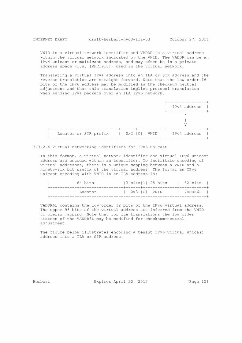
VNID is a virtual network identifier and VADDR is a virtual address within the virtual network indicated by the VNID. The VADDR can be an IPv4 unicast or multicast address, and may often be in a private address space (i.e. [RFC1918]) used in the virtual network.
Translating a virtual IPv4 address into an ILA or SIR address and the reverse translation are straight forward. Note that the low order 16 bits of the IPv6 address may be modified as the checksum-neutral adjustment and that this translation implies protocol translation when sending IPv4 packets over an ILA IPv6 network.
+----------------+ | IPv4 address | +----------------+ ^ | V +----------------------------+------+-----------+----------------+ | Locator or SIR prefix | 0x2 |C| VNID | IPv4 address | +----------------------------------------------------------------+
3.3.2.4 Virtual networking identifiers for IPv6 unicast
In this format, a virtual network identifier and virtual IPv6 unicast address are encoded within an identifier. To facilitate encoding of virtual addresses, there is a unique mapping between a VNID and a ninety-six bit prefix of the virtual address. The format an IPv6 unicast encoding with VNID in an ILA address is:
| 64 bits |3 bits|1| 28 bits | 32 bits | +------------------------------+------+--------------+-----------+ | Locator | 0x3 |C| VNID | VADDR6L | +----------------------------------------------------------------+
VADDR6L contains the low order 32 bits of the IPv6 virtual address. The upper 96 bits of the virtual address are inferred from the VNID to prefix mapping. Note that for ILA translations the low order sixteen of the VADDR6L may be modified for checksum-neutral adjustment.
The figure below illustrates encoding a tenant IPv6 virtual unicast address into a ILA or SIR address.
Herbert Expires April 30, 2017 [Page 12]

INTERNET DRAFT draft-herbert-nvo3-ila-03 October 27, 2016
+----------------------------------------------+-----------------+ | Tenant prefix | VADDR6L | +-----------------------+-------------------------------+--------+ | | +-prefix to VNID-+ | | | v v +---------------------------+------+-----------+-----------------+ | Locator or SIR prefix | 0x3 |C| VNID | VADDR6L | +----------------------------------------------------------------+
This encoding is reversible, given an ILA address, the virtual address visible to the tenant can be deduced:
+---------------------------+------+-----------+-----------------+ | Locator or SIR prefix | 0x3 |C| VNID | VADDR6L | +----------------------------------------+-----------------------+ | | +-VNID to prefix-+ | | | v v +----------------------------------------------+-----------------+ | Tenant prefix | VADDR6L | +----------------------------------------------------------------+
3.3.2.5 Virtual networking identifiers for IPv6 multicast
In this format, a virtual network identifier and virtual IPv6 multicast address are encoded within an identifier.
/* IPv6 multicast address with VNID encoding in an ILA address */ | 64 bits |3 bits|1|28 bits |4 bits| 28 bits | +--------------------------+------+------------------------------+ | Locator | 0x4 |C| VNID |Scope | MADDR6L | +----------------------------------------------------------------+
This format encodes an IPv6 multicast address in an identifier. The scope indicates multicast address scope as defined in [RFC7346]. MADDR6L is the low order 28 bits of the multicast address. The full multicast address is thus:
ff0<Scope>::<MADDRL6 high 12 bits>:<MADDRL6 low 16 bits>
And so can encode multicast addresses of the form:
ff0X::0 to ff0X::0fff:ffff
The figure below illustrates encoding a tenant IPv6 virtual multicast
Herbert Expires April 30, 2017 [Page 13]

INTERNET DRAFT draft-herbert-nvo3-ila-03 October 27, 2016
address in an ILA or SIR address. Note that low order sixteen bits of MADDR6L may be modified to be the checksum-neutral adjustment.
| 12 bits | 4 bits| 84 bits | 28 bits | +---------+-------+-----------------------------------+----------+ | 0xfff | Scope | 0’s | MADDR6L | +-------------+---------------------------------------------+----+ | | +------------------------------------+ | | | v v +--------------------------+------+------------------------------+ | Locator or SIR prefix | 0x4 |C| VNID |Scope | MADDR6L | +----------------------------------------------------------------+
This translation is reversible:
+--------------------------+------+------------------------------+ | Locator or SIR prefix | 0x4 |C| VNID |Scope | MADDR6L | +----------------------------------------------------------------+ | | +------------------------------------+ | | | V V +---------+-------+-----------------------------------+----------+ | 0xfff | Scope | 0’s | MADDR6L | +-------------+---------------------------------------------+----+
3.4 Standard identifier representation addresses
An identifier identifies objects or nodes in a network. For instance, an identifier may refer to a specific host, virtual machine, or tenant system. When a host initiates a connection or sends a packet, it uses the identifier to indicate the peer endpoint of the communication. The endpoints of an established connection context also referenced by identifiers. It is only when the packet is actually being sent over a network that the locator for the identifier needs to be resolved.
In order to maintain compatibility with existing networking stacks and applications, identifiers are encoded in IPv6 addresses using a standard identifier representation (SIR) address. A SIR address is a combination of a prefix which occupies what would be the locator portion of an ILA address, and the identifier in its usual location. The format of a SIR address is:
Herbert Expires April 30, 2017 [Page 14]

INTERNET DRAFT draft-herbert-nvo3-ila-03 October 27, 2016
| 64 bits |3 bits|1| 60 bits | +--------------------------------+-------------------------------+ | SIR prefix | Type |0| Identifier | +----------------------------------------------------------------+
The C-bit (checksum-neutral mapping) MUST be zero for a SIR address. Type may be any identifier type except zero (interface identifiers)
A SIR prefix may be site-local, or globally routable. A globally routable SIR prefix facilitates connectivity between hosts on the Internet and ILA nodes. A gateway between a site’s network and the Internet can translate between SIR prefix and locator for an identifier. A network may have multiple SIR prefixes where each prefix defines a unique identifier space.
Locators MUST only be associated with one SIR prefix. This ensures that if a translation from a SIR address to an ILA address is performed when sending a packet, the reverse translation at the receiver yields the same SIR address that was seen at the transmitter. This also ensures that a reverse checksum-neutral mapping can be performed at a receiver to restore the addresses that were included in a pseudo header for setting a transport checksum.
A standard identifier representation address can be used as the externally visible address for a node. This can used throughout the network, returned in DNS AAAA records [RFC3363], used in logging, etc. An application can use a SIR address without knowledge that it encodes an identifier.
3.4.1 SIR for locally unique identifiers
The SIR address for a locally unique identifier has format:
| 64 bits |3 bits|1| 60 bits | +--------------------------------+-------------------------------+ | SIR prefix | 0x1 |0|Locally unique ident. | +----------------------------------------------------------------+
3.4.2 SIR for virtual addresses
A virtual address can be encoded using the standard identifier representation. For example, the SIR address for an IPv6 virtual address may be:
| 64 bits |3 bits|1| 28 bits | 32 bits | +--------------------------------+------+------------+-----------+ | SIR prefix | 0x3 |0| VNID | VADDRL6 | +----------------------------------------------------------------+
Herbert Expires April 30, 2017 [Page 15]
INTERNET DRAFT draft-herbert-nvo3-ila-03 October 27, 2016
Note that this allows three representations of the same address in he network: as a virtual address, a SIR address, and an ILA address.
3.4.3 SIR domains
Each SIR prefix defines a SIR domain. A SIR domain is a unique name space for identifiers within a domain. The full identity of a node is thus determined by an identifier and SIR domain (SIR prefix). Locators MUST map to only one SIR domain in order to ensure that translation from a locator to SIR prefix is unambiguous.
4 Operation
This section describes operation methods for using identifier-locator addressing.
4.1 Identifier to locator mapping
An application initiates a communication or flow using a SIR address or virtual address for a destination. In order to send a packet on the network, the destination address is translated by an ILA router or an ILA host in the path. An ILA node maintains a list of mappings from identifier to locator to perform this translation.
The mechanisms of propagating and maintaining identifier to locator mappings are outside the scope of this document.
4.2 Address translations
With ILA, address translation is performed to convert SIR addresses to ILA addresses, and ILA addresses to SIR addresses. Translation is usually done on a destination address as a form of source routing, however translation on source virtual addresses to SIR addresses can also be done to support some network virtualization scenarios (see appendix A.7 for example).
4.2.1 SIR to ILA address translation
When translating a SIR address to an ILA address the SIR prefix in the address is overridden with a locator, and checksum neutral mapping may be performed. Since this operation is potentially done for every packet the process should be very efficient (particularly the lookup and checksum processing operations).
The typical steps to transmit a packet using ILA are:
1) Host stack creates a packet with source address set to a local address (possibly a SIR address) for the local identity, and
Herbert Expires April 30, 2017 [Page 16]
INTERNET DRAFT draft-herbert-nvo3-ila-03 October 27, 2016
the destination address is set to the SIR address or virtual address for the peer. The peer address may have been discovered through DNS or other means.
2) An ILA router or host translates the packet to use the locator. If the original destination address is a SIR address then the SIR prefix is overwritten with the locator. If the original packet is a virtually addressed tenant packet then the virtual address is translated per section 3.3.2. The locator is discovered by a lookup in the locator to identifier mappings.
3) The ILA node performs checksum-neutral mapping if configured for that (section 4.4.1).
4) Packet is forwarded on the wire. The network routes the packet to the host indicated by the locator.
4.2.2 ILA to SIR address translation
When a destination node (ILA router or end host) receives an ILA addressed packet, the ILA address MUST be translated back to a SIR address (or tenant address) before upper layer processing.
The steps of receive processing are:
1) Packet is received. The destination locator is verified to match a locator assigned to the host.
2) A lookup is performed on the destination identifier to find if it addresses a local identifier. If match is found, either the locator is overwritten with SIR prefix (for locally unique identifier type) or the address is translated back to a tenant virtual address as shown in appendix A.7.
3) Perform reverse checksum-neutral mapping if C-bit is set (section 4.4.1).
4) Perform any optional policy checks; for instance that the source may send a packet to the destination address, that packet is not illegitimately crossing virtual networks, etc.
5) Forward packet to application processing.
4.3 Virtual networking operation
When using ILA with virtual networking identifiers, address translation is performed to convert tenant virtual network and virtual addresses to ILA addresses, and ILA addresses back to a
Herbert Expires April 30, 2017 [Page 17]
INTERNET DRAFT draft-herbert-nvo3-ila-03 October 27, 2016
virtual network and tenant’s virtual addresses. Translation may occur on either source address, destination address, or both (see scenarios for virtual networking in Appendix A). Address translation is performed similar to the SIR translation cases described above.
4.3.1 Crossing virtual networks
With explicit configuration, virtual network hosts may communicate directly with virtual hosts in another virtual network by using SIR addresses for virtualization in both the source and destination addresses. This might be done to allow services in one virtual network to be accessed from another (by prior agreement between tenants). See appendix A.13 for example of ILA addressing for such a scenario.
4.3.2 IPv4/IPv6 protocol translation
An IPv4 tenant may send a packet that is converted to an IPv6 packet with ILA addresses. Similarly, an IPv6 packet with ILA addresses may be converted to an IPv4 packet to be received by an IPv4-only tenant. These are IPv4/IPv6 stateless protocol translations as described in [RFC6144] and [RFC6145]. See appendix A.12 for a description of these scenarios.
4.4 Transport layer checksums
Packets undergoing ILA translation may encapsulate transport layer checksums (e.g. TCP or UDP) that include a pseudo header that is affected by the translation.
ILA provides two alternatives do deal with this:
o Perform a checksum-neutral mapping to ensure that an encapsulated transport layer checksum is kept correct on the wire.
o Send the checksum as-is, that is send the checksum value based on the pseudo header before translation.
Some intermediate devices that are not the actual end point of a transport protocol may attempt to validate transport layer checksums. In particular, many Network Interface Cards (NICs) have offload capabilities to validate transport layer checksums (including any pseudo header) and return a result of validation to the host. Typically, these devices will not drop packets with bad checksums, they just pass a result to the host. Checksum offload is a performance benefit, so if packets have incorrect checksums on the wire this benefit is lost. With this incentive, applying a checksum-
Herbert Expires April 30, 2017 [Page 18]

INTERNET DRAFT draft-herbert-nvo3-ila-03 October 27, 2016
neutral mapping is the recommended alternative. If it is known that the addresses of a packet are not included in a transport checksum, for instance a GRE packet is being encapsulated, then a source may choose not to perform checksum-neutral mapping.
4.4.1 Checksum-neutral mapping
When a change is made to one of the IP header fields in the IPv6 pseudo-header checksum (such as one of the IP addresses), the checksum field in the transport layer header may become invalid. Fortunately, an incremental change in the area covered by the Internet standard checksum [RFC1071] will result in a well-defined change to the checksum value [RFC1624]. So, a checksum change caused by modifying part of the area covered by the checksum can be corrected by making a complementary change to a different 16-bit field covered by the same checksum.
ILA can perform a checksum-neutral mapping when a SIR prefix or virtual address is translated to a locator in an IPv6 address, and performs the reverse mapping when translating a locator back to a SIR prefix or virtual address. The low order sixteen bits of the identifier contain the checksum adjustment value for ILA.
On transmission, the translation process is:
1) Compute the one’s complement difference between the SIR prefix and the locator. Fold this value to 16 bits (add-with-carry four 16-bit words of the difference).
2) Add-with-carry the bit-wise not of the 0x1000 (i.e. 0xefff) to the value from #1. This compensates the checksum for setting the C-bit.
3) Add-with-carry the value from #2 to the low order sixteen bits of the identifier.
4) Set the resultant value from #3 in the low order sixteen bits of the identifier and set the C-bit.
Note that the "adjustment" (the 16-bit value set in the identifier in set #3) is fixed for a given SIR to locator mapping, so the adjustment value can be saved in an associated data structure for a mapping to avoid computing it for each translation.
On reception of an ILA addressed packet, if the C-bit is set in an ILA address:
1) Compute the one’s complement difference between the locator in
Herbert Expires April 30, 2017 [Page 19]

INTERNET DRAFT draft-herbert-nvo3-ila-03 October 27, 2016
the address and the SIR prefix that the locator is being translated to. Fold this value to 16 bits (add-with-carry four 16-bit words of the difference).
2) Add-with-carry 0x1000 to the value from #1. This compensates the checksum for clearing the C-bit.
3) Add-with-carry the value from #2 to the low order sixteen bits of the identifier.
4) Set the resultant value from #3 in the low order sixteen bits of the identifier and clear the C-bit. This restores the original identifier sent in the packet.
4.4.2 Sending an unmodified checksum
When sending an unmodified checksum, the checksum is incorrect as viewed in the packet on the wire. At the receiver, ILA translation of the destination ILA address back to the SIR address occurs before transport layer processing. This ensures that the checksum can be verified when processing the transport layer header containing the checksum. Intermediate devices are not expected to drop packets due to a bad transport layer checksum.
4.5 Address selection
There may be multiple possibilities for creating either a source or destination address. A node may be associated with more than one identifier, and there may be multiple locators for a particular identifier. The choice of locator or identifier is implementation or configuration specific. The selection of an identifier occurs at flow creation and must be invariant for the duration of the flow. Locator selection must be done at least once per flow, and the locator associated with the destination of a flow may change during the lifetime of the flow (for instance in the case of a migrating connection it will change). ILA address selection should follow specifications in Default Address Selection for Internet Protocol Version 6 (IPv6) [RFC6724].
4.6 Duplicate identifier detection
As part of implementing the locator to identifier mapping, duplicate identifier detection should be implemented in a centralized control plane. A registry of identifiers could be maintained (possibly in association the identifier to locator mapping database). When a node creates an identifier it registers the identifier, and when the identifier is no longer in use (e.g. task completes) the identifier is unregistered. The control plane should able to detect a
Herbert Expires April 30, 2017 [Page 20]

INTERNET DRAFT draft-herbert-nvo3-ila-03 October 27, 2016
registration attempt for an existing identifier and deny the request.
4.7 ICMP error handling
A packet that contains an ILA address may cause ICMP errors within the network. In this case the ICMP data contains an IP header with an ILA address. ICMP messages are sent back to the source address in the packet. Upon receiving an ICMP error the host will process it differently depending on whether it is ILA capable.
4.7.1 Handling ICMP errors by ILA capable hosts
If a host is ILA capable it can attempt to reverse translate the ILA address in the destination of a header in the ICMP data back to a SIR address that was originally used to transmit the packet. The steps are:
1) Assume that the upper sixty-four bits of the destination address in the ICMP data is a locator. Try match these bits back to a SIR address. If the host is only in one SIR domain, then the mapping to SIR address is implicit. If the host is in multiple domains then a locator to SIR addresses table can be maintained for this lookup.
2) If the identifier is marked with checksum-neutral mapping, undo the checksum-neutral using the SIR address found in #1. The resulting identifier address is potentially the original address used to send the packet.
3) Lookup the identifier in the identifier to locator mapping table. If an entry is found compare the locator in the entry to the locator (upper sixty-four bits) of the destination address in the IP header of the ICMP data. If hese match then proceed to next step.
4) Overwrite the upper sixty-four bits of the destination address in the ICMP data with the found SIR address and overwrite the low order sixty-four bits with the found identifier (the result of undoing checksum-neutral mapping). The resulting address should be the original SIR address used in sending. The ICMP error packet can then be received by the stack for further processing.
4.7.2 Handling ICMP errors by non-ILA capable hosts
A non-ILA capable host may receive an ICMP error generated by the network that contains an ILA address in an IP header contained in the ICMP data. This would happen in the case that an ILA router performed
Herbert Expires April 30, 2017 [Page 21]

INTERNET DRAFT draft-herbert-nvo3-ila-03 October 27, 2016
translation on a packet the host sent and that packet subsequently generated an ICMP error. In this case the host receiving the error message will attempt to find the connection state corresponding to the packet in headers the ICMP data. Since the host is unaware of ILA the lookup for connection state should fail. Because the host cannot recover the original addresses it used to send the packet, it won’t be able any to derive any useful information about the original destination of the packet that it sent.
If packets for a flow are always routed through an ILA router in both directions, for example ILA routers are coincident with edge routes in a network, then ICMP errors could be intercepted by an intermediate node which could translate the destination addresses in ICMP data back to the original SIR addresses. A receiving host would then see the destination address in the packet of the ICMP data to be that it used to transmit the original packet.
4.8 Multicast
ILA is generally not intended for use with multicast. In the case of multicast, routing of packets is based on the source address. Neither the SIR address nor an ILA address is suitable for use as a source address in a multicast packet. A SIR address is unroutable and hence would make a multicast packet unroutable if used as a source address. Using an ILA address as the source address makes the multicast packet routable, but this exposes ILA address to applications which is especially problematic on a multicast receiver that doesn’t support ILA.
If all multicast receivers are known to support ILA, a local locator address may be used in the source address of the multicast packet. In this case, each receiver will translate the source address from an ILA address to a SIR address before delivering packets to an application.
5 Motivation for ILA
5.1 Use cases
5.1.1 Multi-tenant virtualization
In multi-tenant virtualization overlay networks are established for tenants to provide virtual networks. Each tenant may have one or more virtual networks and a tenant’s nodes are assigned virtual addresses within virtual networks. Identifier-locator addressing may be used as an alternative to traditional network virtualization encapsulation protocols used to create overlay networks (e.g. VXLAN [RFC7348]). Section 5.2,4 describes the advantages of using ILA in lieu of
Herbert Expires April 30, 2017 [Page 22]

INTERNET DRAFT draft-herbert-nvo3-ila-03 October 27, 2016
encapsulation protocols.
Tenant systems (e.g. VMs) run on physical hosts and may migrate to different hosts. A tenant system is identified by a virtual address and virtual networking identifier of a corresponding virtual network. ILA can encode the virtual address and a virtual networking identifier in an ILA identifier. Each identifier is mapped to a locator that indicates the current host where the tenant system resides. Nodes that send to the tenant system set the locator per the mapping. When a tenant system migrates its identifier to locator mapping is updated and communicating nodes will use the new mapping.
5.1.2 Datacenter virtualization
Datacenter virtualization virtualizes networking resources. Various objects within a datacenter can be assigned addresses and serve as logical endpoints of communication. A large address space, for example that of IPv6, allows addressing to be used beyond the traditional concepts of host based addressing. Addressed objects can include tasks, virtual IP addresses (VIPs), pieces of content, disk blocks, etc. Each object has a location which is given by the host on which an object resides. Some objects may be migratable between hosts such that their location changes over time.
Objects are identified by a unique identifier within a namespace for the datacenter (appendix B discusses methods to create unique identifiers for ILA). Each identifier is mapped to a locator that indicates the current host where the object resides. Nodes that send to an object set the locator per the mapping. When an object migrates its identifier to locator mapping is updated and communicating nodes will use the new mapping.
A datacenter object of particular interest is tasks, units of execution for for applications. The goal of virtualzing tasks is to maximize resource efficiency and job scheduling. Tasks share many properties of tenant systems, however they are finer grained objects, may have a shorter lifetimes, and are likely created in greater numbers. Appendix C provides more detail and motivation for virtualizing tasks using ILA.
5.1.3 Device mobility
ILA may be applied as a solution for mobile devices. These are devices, smart phones for instance, that physically move between different networks. The goal of mobility is to provide a seamless transition when a device moves from one network to another.
Each mobile device is identified by unique identifier within some
Herbert Expires April 30, 2017 [Page 23]

INTERNET DRAFT draft-herbert-nvo3-ila-03 October 27, 2016
provider domain. ILA encodes the identifier for the device in an ILA identifier. Each identifier is mapped to a locator that indicates the current network or point of attachment for the device. Nodes that send to the device set the locator per the mapping. When a mobile device moves between networks its identifier to locator mapping is updated and communicating nodes will use the new mapping.
5.2 Alternative methods
This section discusses the merits of alternative solution that have been proposed to provide network virtualization or mobility in IPv6.
5.2.1 ILNP
ILNP splits an address into a locator and identifier in the same manner as ILA. ILNP has characteristics, not present in ILA, that prevent it from being a practical solution:
o ILNP requires that transport layer protocol implementations must be modified to work over ILNP.
o ILNP can only be implemented in end hosts, not within the network. This essentially requires that all end hosts need to be modified to participate in mobility.
o ILNP employs IPv6 extension headers which are mostly considered non-deployable. ILA does not use these.
o Core support for ILA is in upstream Linux, to date there is no publicly available source code for ILNP.
o ILNP involves DNS to distribute mapping information, ILA assumes mapping information is not part of naming.
5.2.2 Flow label as virtual network identifier
The IPv6 flow label could conceptually be used as a 20-bit virtual network identifier in order to indicate a packet is sent on an overlay network. In this model the addresses may be virtual addresses within the specified virtual network. Presumably, the tuple of flow- label and addresses could be used by switches to forward virtually addressed packets.
This approach has some issues:
o Forwarding virtual packets to their physical location would require specialized switch support.
Herbert Expires April 30, 2017 [Page 24]
INTERNET DRAFT draft-herbert-nvo3-ila-03 October 27, 2016
o The flow label is only twenty bits, this is too small to be a discriminator in forwarding a virtual packet to a specific destination. Conceptually, the flow label might be used in a type of label switching to solve that.
o The flow label is not considered immutable in transit, intermediate devices may change it.
o The flow label is not part of the pseudo header for transport checksum calculation, so it is not covered by any transport (or other) checksums.
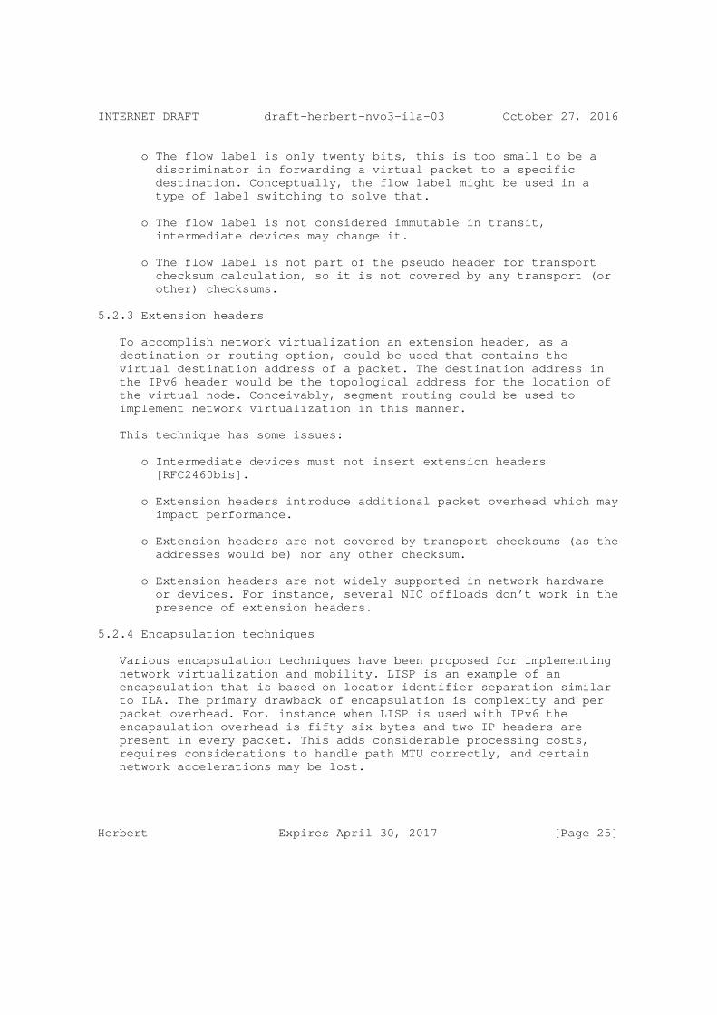
5.2.3 Extension headers
To accomplish network virtualization an extension header, as a destination or routing option, could be used that contains the virtual destination address of a packet. The destination address in the IPv6 header would be the topological address for the location of the virtual node. Conceivably, segment routing could be used to implement network virtualization in this manner.
This technique has some issues:
o Intermediate devices must not insert extension headers [RFC2460bis].
o Extension headers introduce additional packet overhead which may impact performance.
o Extension headers are not covered by transport checksums (as the addresses would be) nor any other checksum.
o Extension headers are not widely supported in network hardware or devices. For instance, several NIC offloads don’t work in the presence of extension headers.
5.2.4 Encapsulation techniques
Various encapsulation techniques have been proposed for implementing network virtualization and mobility. LISP is an example of an encapsulation that is based on locator identifier separation similar to ILA. The primary drawback of encapsulation is complexity and per packet overhead. For, instance when LISP is used with IPv6 the encapsulation overhead is fifty-six bytes and two IP headers are present in every packet. This adds considerable processing costs, requires considerations to handle path MTU correctly, and certain network accelerations may be lost.
Herbert Expires April 30, 2017 [Page 25]

INTERNET DRAFT draft-herbert-nvo3-ila-03 October 27, 2016
6 IANA Considerations
There are no IANA considerations in this specification.
7 References
7.1 Normative References
[RFC2460] Deering, S. and R. Hinden, "Internet Protocol, Version 6 (IPv6) Specification", RFC 2460, December 1998.
[RFC2460bis] Deering, S. and R. Hinden, "Internet Protocol, Version 6 (IPv6) Specification", draft-ietf-6man-rfc2460bis-03, January 2016.
[RFC4291] Hinden, R. and S. Deering, "IP Version 6 Addressing Architecture", RFC 4291, February 2006.
[RFC6296] Wasserman, M. and F. Baker, "IPv6-to-IPv6 Network Prefix Translation", RFC 6296, June 2011.
[RFC1071] Braden, R., Borman, D., Partridge, C., and W. Plummer, "Computing the Internet checksum", RFC 1071, September 1988.
[RFC1624] Rijsinghani, A., "Computation of the Internet Checksum via Incremental Update", RFC 1624, May 1994.
[RFC6724] Thaler, D., Ed., Draves, R., Matsumoto, A., and T. Chown, "Default Address Selection for Internet Protocol Version 6 (IPv6)", RFC 6724, September 2012.
7.2 Informative References
[RFC6740] RJ Atkinson and SN Bhatti, "Identifier-Locator Network Protocol (ILNP) Architectural Description", RFC 6740, November 2012.
[RFC6741] RJ Atkinson and SN Bhatti, "Identifier-Locator Network Protocol (ILNP) Engineering Considerations", RFC 6741, November 2012.
[RFC1918] Rekhter, Y., Moskowitz, B., Karrenberg, D., de Groot, G., and E. Lear, "Address Allocation for Private Internets", BCP 5, RFC 1918, February 1996.
[RFC3363] Bush, R., Durand, A., Fink, B., Gudmundsson, O., and T. Hain, "Representing Internet Protocol version 6 (IPv6)
Herbert Expires April 30, 2017 [Page 26]

INTERNET DRAFT draft-herbert-nvo3-ila-03 October 27, 2016
Addresses in the Domain Name System (DNS)", RFC 3363, August 2002.
[RFC3587] Hinden, R., Deering, S., and E. Nordmark, "IPv6 Global Unicast Address Format", RFC 3587, August 2003.
[RFC4193] Hinden, R. and B. Haberman, "Unique Local IPv6 Unicast Addresses", RFC 4193, October 2005.
[RFC6144] Baker, F., Li, X., Bao, C., and K. Yin, "Framework for IPv4/IPv6 Translation", RFC 6144, April 2011.
[NVO3ARCH] Black, D., Hudson, J., Kreeger, L., Lasserre, M., and Narten, T., "An Architecture for Overlay Networks (NVO3)", draft-ietf-nvo3-arch-03
[GUE] Herbert, T., and Yong, L., "Generic UDP Encapsulation", draft-herbert-gue-02, work in progress.
[GUESEC] Yong, L., and Herbert, T. "Generic UDP Encapsulation (GUE) for Secure Transport", draft-hy-gue-4-secure-transport- 00, work in progress
8 Acknowledgments
The author would like to thank Mark Smith, Lucy Yong, Erik Kline, Saleem Bhatti, Petr Lapukhov, Blake Matheny, Doug Porter, Pierre Pfister, and Fred Baker for their insightful comments for this draft; Roy Bryant, Lorenzo Colitti, Mahesh Bandewar, and Erik Kline for their work on defining and applying ILA.
Herbert Expires April 30, 2017 [Page 27]
INTERNET DRAFT draft-herbert-nvo3-ila-03 October 27, 2016
Appendix A: Communication scenarios
This section describes the use of identifier-locator addressing in several scenarios.
A.1 Terminology for scenario descriptions
A formal notation for identifier-locator addressing with ILNP is described in [RFC6740]. We extend this to include for network virtualization cases.
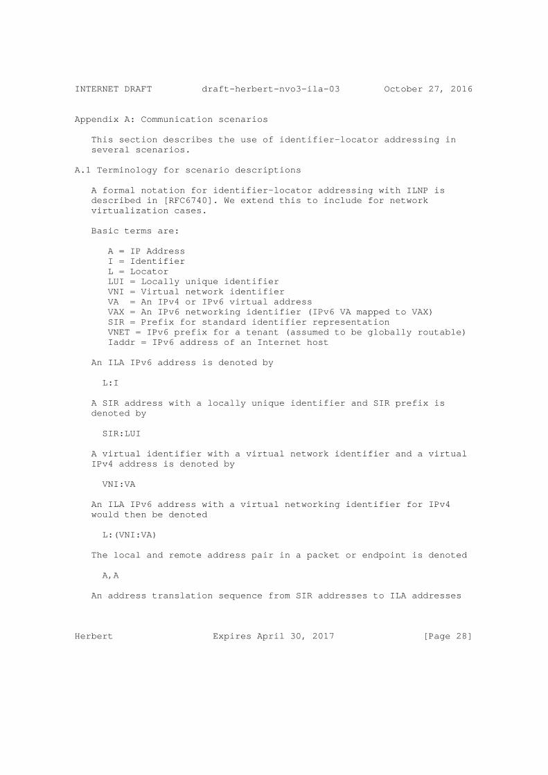
Basic terms are:
A = IP Address I = Identifier L = Locator LUI = Locally unique identifier VNI = Virtual network identifier VA = An IPv4 or IPv6 virtual address VAX = An IPv6 networking identifier (IPv6 VA mapped to VAX) SIR = Prefix for standard identifier representation VNET = IPv6 prefix for a tenant (assumed to be globally routable) Iaddr = IPv6 address of an Internet host
An ILA IPv6 address is denoted by
L:I
A SIR address with a locally unique identifier and SIR prefix is denoted by
SIR:LUI
A virtual identifier with a virtual network identifier and a virtual IPv4 address is denoted by
VNI:VA
An ILA IPv6 address with a virtual networking identifier for IPv4 would then be denoted
L:(VNI:VA)
The local and remote address pair in a packet or endpoint is denoted
A,A
An address translation sequence from SIR addresses to ILA addresses
Herbert Expires April 30, 2017 [Page 28]
INTERNET DRAFT draft-herbert-nvo3-ila-03 October 27, 2016
for transmission on the network and back to SIR addresses at a receiver has notation:
A,A -> L:I,A -> A,A
A.2 Identifier objects
Identifier-locator addressing is broad enough in scope to address many different types of networking entities. For the purposes of this section we classify these as "objects" and "tenant systems".
Objects encompass uses where nodes are address by local unique identifiers (LUI). In the scenarios below objects are denoted by OBJ.
Tenant systems are those associated with network virtualization that have virtual addresses (that is they are addressed by VNI:VA). In the scenarios below tenant systems are denoted by TS.
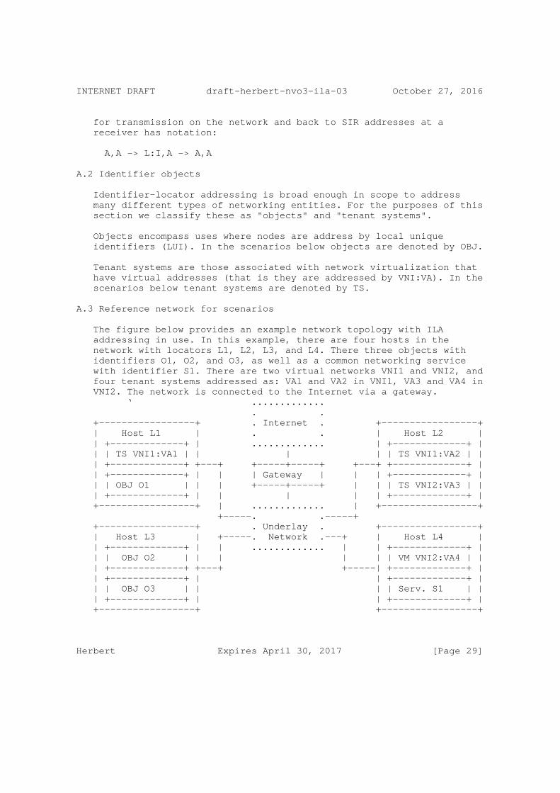
A.3 Reference network for scenarios
The figure below provides an example network topology with ILA addressing in use. In this example, there are four hosts in the network with locators L1, L2, L3, and L4. There three objects with identifiers O1, O2, and O3, as well as a common networking service with identifier S1. There are two virtual networks VNI1 and VNI2, and four tenant systems addressed as: VA1 and VA2 in VNI1, VA3 and VA4 in VNI2. The network is connected to the Internet via a gateway. ‘ ............. . . +-----------------+ . Internet . +-----------------+ | Host L1 | . . | Host L2 | | +-------------+ | ............. | +-------------+ | | | TS VNI1:VA1 | | | | | TS VNI1:VA2 | | | +-------------+ +---+ +-----+-----+ +---+ +-------------+ | | +-------------+ | | | Gateway | | | +-------------+ | | | OBJ O1 | | | +-----+-----+ | | | TS VNI2:VA3 | | | +-------------+ | | | | | +-------------+ | +-----------------+ | ............. | +-----------------+ +-----. .-----+ +-----------------+ . Underlay . +-----------------+ | Host L3 | +-----. Network .---+ | Host L4 | | +-------------+ | | ............. | | +-------------+ | | | OBJ O2 | | | | | | VM VNI2:VA4 | | | +-------------+ +---+ +-----| +-------------+ | | +-------------+ | | +-------------+ | | | OBJ O3 | | | | Serv. S1 | | | +-------------+ | | +-------------+ | +-----------------+ +-----------------+
Herbert Expires April 30, 2017 [Page 29]

INTERNET DRAFT draft-herbert-nvo3-ila-03 October 27, 2016
Several communication scenarios can be considered:
1) Object to object 2) Object to Internet 3) Internet to object 4) Tenant system to local service 5) Object to tenant system 6) Tenant system to Internet 7) Internet to tenant system 8) IPv4 tenant system to service 9) Tenant system to tenant system same virtual network using IPv6 10) Tenant system to tenant system in same virtual network using IPv4 11) Tenant system to tenant system in different virtual network using IPv6 12) Tenant system to tenant system in different virtual network using IPv4 13) IPv4 tenant system to IPv6 tenant system in different virtual networks
A.4 Scenario 1: Object to task
The transport endpoints for object to object communication are the SIR addresses for the objects. When a packet is sent on the wire, the locator is set in the destination address of the packet. On reception the destination addresses is converted back to SIR representation for processing at the transport layer.
If object O1 is communicating with object O2, the ILA translation sequence would be:
SIR:O1,SIR:O2 -> // Transport endpoints on O1 SIR:O1,L3:O2 -> // ILA used on the wire SIR:O1,SIR:O2 // Received at O2
A.5 Scenario 2: Object to Internet
Communication from an object to the Internet is accomplished through use of a SIR address (globally routable) in the source address of packets. No ILA translation is needed in this path.
If object O1 is sending to an address Iaddr on the Internet, the packet addresses would be:
SIR:O1,Iaddr
A.6 Scenario 3: Internet to object
Herbert Expires April 30, 2017 [Page 30]
INTERNET DRAFT draft-herbert-nvo3-ila-03 October 27, 2016
An Internet host transmits a packet to a task using an externally routable SIR address. The SIR prefix routes the packet to a gateway for the datacenter. The gateway translates the destination to an ILA address.
If a host on the Internet with address Iaddr sends a packet to object O3, the ILA translation sequence would be:
Iaddr,SIR:O3 -> // Transport endpoint at Iaddr Iaddr,L1:O3 -> // On the wire in datacenter Iaddr,SIR:O3 // Received at O3
A.7 Scenario 4: Tenant system to service
A tenant can communicate with a datacenter service using the SIR address of the service.
If TS VA1 is communicating with service S1, the ILA translation sequence would be:
VNET:VA1,Saddr-> // Transport endpoints in TS SIR:(VNET:VA1):Saddr-> // On the wire SIR:(VNET:VA1):Saddr // Received at S1
Where VNET is the address prefix for the tenant and Saddr is the IPv6 address of the service.
The ILA translation sequence in the reverse path, service to tenant system, would be:
Saddr,SIR:(VNET:VA1) // Transport endpoints in S1 Saddr,L1:(VNET:VA1) // On the wire Saddr,VNET:VA1 // Received at the TS
Note that from the point of view of the service task there is no material difference between a peer that is a tenant system versus one which is another task.
A.8 Scenario 5: Object to tenant system
An object can communicate with a tenant system through it’s externally visible address.
If object O2 is communicating with TS VA4, the ILA translation sequence would be:
SIR:O2,VNET:VA4 -> // Transport endpoints at T2 SIR:O2,L4:(VNI2:VAX4) -> // On the wire
Herbert Expires April 30, 2017 [Page 31]

INTERNET DRAFT draft-herbert-nvo3-ila-03 October 27, 2016
SIR:O2,VNET:VA4 // Received at TS
A.9 Scenario 6: Tenant system to Internet
Communication from a TS to the Internet assumes that the VNET for the TS is globally routable, hence no ILA translation would be needed.
If TS VA4 sends a packet to the Internet, the addresses would be:
VNET:VA4,Iaddr
A.10 Scenario 7: Internet to tenant system
An Internet host transmits a packet to a tenant system using an externally routable tenant prefix and address. The prefix routes the packet to a gateway for the datacenter. The gateway translates the destination to an ILA address.
If a host on the Internet with address Iaddr is sending to TS VA4, the ILA translation sequence would be:
Iaddr,VNET:VA4 -> // Endpoint at Iaddr Iaddr,L4:(VNI2:VAX4) -> // On the wire in datacenter Iaddr,VNET:VA4 // Received at TS
A.11 Scenario 8: IPv4 tenant system to object
A TS that is IPv4-only may communicate with an object using protocol translation. The object would be represented as an IPv4 address in the tenant’s address space, and stateless NAT64 should be usable as described in [RFC6145].
If TS VA2 communicates with object O3, the ILA translation sequence would be:
VA2,ADDR3 -> // IPv4 endpoints at TS SIR:(VNI1:VA2),L3:O3 -> // On the wire in datacenter SIR:(VNI1:VA2),SIR:O3 // Received at task
VA2 is the IPv4 address in the tenant’s virtual network, ADDR4 is an address in the tenant’s address space that maps to the network service.
The reverse path, task sending to a TS with an IPv4 address, requires a similar protocol translation.
For object O3 communicate with TS VA2, the ILA translation sequence would be:
Herbert Expires April 30, 2017 [Page 32]
INTERNET DRAFT draft-herbert-nvo3-ila-03 October 27, 2016
SIR:O3,SIR:(VNI1:VA2) -> // Endpoints at T4 SIR:O3,L2:(VNI1:VA2) -> // On the wire in datacenter ADDR4,VA2 // IPv4 endpoint at TS
A.12 Tenant to tenant system in the same virtual network
ILA may be used to allow tenants within a virtual network to communicate without the need for explicit encapsulation headers.
A.12.1 Scenario 9: TS to TS in the same VN using IPV6
If TS VA1 sends a packet to TS VA2, the ILA translation sequence would be:
VNET:VA1,VNET:VA2 -> // Endpoints at VA1 VNET:VA1,L2:(VNI1,VAX2) -> // On the wire VNET:VA1,VNET:VA2 -> // Received at VA2
A.12.2 Scenario 10: TS to TS in same VN using IPv4
For two tenant systems to communicate using IPv4 and ILA, IPv4/IPv6 protocol translation is done both on the transmit and receive.
If TS VA1 sends an IPv4 packet to TS VA2, the ILA translation sequence would be:
VA1,VA2 -> // Endpoints at VA1 SIR:(VNI1:VA1),L2:(VNI1,VA2) -> // On the wire VA1,VA2 // Received at VA2
Note that the SIR is chosen by an ILA node as an appropriate SIR prefix in the underlay network. Tenant systems do not use SIR address for this communication, they only use virtual addresses.
A.13 Tenant system to tenant system in different virtual networks
A tenant system may be allowed to communicate with another tenant system in a different virtual network. This should only be allowed with explicit policy configuration.
A.13.1 Scenario 11: TS to TS in different VNs using IPV6
For TS VA4 to communicate with TS VA1 using IPv6 the translation sequence would be:
VNET2:VA4,VNET1:VA1-> // Endpoint at VA4 VNET2:VA4,L1:(VNI1,VAX1)-> // On the wire VNET2:VA4,VNET1:VA1 // Received at VA1
Herbert Expires April 30, 2017 [Page 33]
INTERNET DRAFT draft-herbert-nvo3-ila-03 October 27, 2016
Note that this assumes that VNET1 and VNET2 are globally routable between the two virtual networks.
A.13.2 Scenario 12: TS to TS in different VNs using IPv4
To allow IPv4 tenant systems in different virtual networks to communicate with each other, an address representing the peer would be mapped into each tenant’s address space. IPv4/IPv6 protocol translation is done on transmit and receive.
For TS VA4 to communicate with TS VA1 using IPv4 the translation sequence may be:
VA4,SADDR1 -> // IPv4 endpoint at VA4 SIR:(VNI2:VA4),L1:(VNI1,VA1)-> // On the wire SADDR4,VA1 // Received at VA1
SADDR1 is the mapped address for VA1 in VA4’s address space, and SADDR4 is the mapped address for VA4 in VA1’s address space.
A.13.3 Scenario 13: IPv4 TS to IPv6 TS in different VNs
Communication may also be mixed so that an IPv4 tenant system can communicate with an IPv6 tenant system in another virtual network. IPv4/IPv6 protocol translation is done on transmit.
For TS VA4 using IPv4 to communicate with TS VA1 using IPv6 the translation sequence may be:
VA4,SADDR1 -> // IPv4 endpoint at VA4 SIR:(VNI2:VA4),L1:(VNI1,VAX1)-> // On the wire SIR:(VNI2:VA4),VNET1:VA1 // Received at VA1
SADDR1 is the mapped IPv4 address for VA1 in VA4’s address space.
In the reverse direction, TS VA1 using IPv6 would communicate with TS VA4 with the translation sequence:
VNET1:VA1,SIR:(VNI2:VA4) // Endpoint at VA1 VNET1:VA1,L4:(VNI2:VA4) // On the wire SADDR1,VA4 // Received at VA4
Herbert Expires April 30, 2017 [Page 34]

INTERNET DRAFT draft-herbert-nvo3-ila-03 October 27, 2016
Appendix B: unique identifier generation
The unique identifier type of ILA identifiers can address 2**60 objects. This appendix describes some method to perform allocation of identifiers for objects to avoid duplicated identifiers being allocated.
B.1 Globally unique identifiers method
For small to moderate sized deployments the technique for creating locally assigned global identifiers described in [RFC4193] could be used. In this technique a SHA-1 digest of the time of day in NTP format and an EUI-64 identifier of the local host is performed. N bits of the result are used as the globally unique identifier.
The probability that two or more of these IDs will collide can be approximated using the formula:
P = 1 - exp(-N**2 / 2**(L+1))
where P is the probability of collision, N is the number of identifiers, and L is the length of an identifier.
The following table shows the probability of a collision for a range of identifiers using a 60-bit length.
Identifiers Probability of Collision 1000 4.3368*10^-13 10000 4.3368*10^-11 100000 4.3368*10^-09 1000000 4.3368*10^-07
Note that locally unique identifiers may be ephemeral, for instance a task may only exist for a few seconds. This should be considered when determining the probability of identifier collision.
B.2 Universally Unique Identifiers method
For larger deployments, hierarchical allocation may be desired. The techniques in Universally Unique Identifier (UUID) URN ([RFC4122]) can be adapted for allocating unique object identifiers in sixty bits. An identifier is split into two components: a registrar prefix and sub-identifier. The registrar prefix defines an identifier block which is managed by an agent, the sub-identifier is a unique value within the registrar block.
For instance, each host in a network could be an agent so that unique identifiers for objects could be created autonomously be the host.
Herbert Expires April 30, 2017 [Page 35]

INTERNET DRAFT draft-herbert-nvo3-ila-03 October 27, 2016
The identifier might be composed of a twenty-four bit host identifier followed by a thirty-six bit timestamp. Assuming that a host can allocate up to 100 identifiers per second, this allows about 21.8 years before wrap around.
/* LUI identifier with host registrar and timestamp */ |3 bits|1| 24 bits | 36 bits | +------+-------------------+-------------------------------------+ | 0x1 |C| Host identifier | Timestamp Identifier | +----------------------------------------------------------------+
Appendix C: Datacenter task virtualization
This section describes some details to apply ILA to virtualizing tasks in a datacenter.
C.1 Address per task
Managing the port number space for services within a datacenter is a nontrivial problem. When a service task is created, it may run on arbitrary hosts. The typical scenario is that the task will be started on some machine and will be assigned a port number for its service. The port number must be chosen dynamically to not conflict with any other port numbers already assigned to tasks on the same machine (possibly even other instances of the same service). A canonical name for the service is entered into a database with the host address and assigned port. When a client wishes to connect to the service, it queries the database with the service name to get both the address of an instance as well as its port number. Note that DNS is not adequate for the service lookup since it does not provide port numbers.
With ILA, each service task can be assigned its own IPv6 address and therefore will logically be assigned the full port space for that address. This a dramatic simplification since each service can now use a publicly known port number that does not need to unique between services or instances. A client can perform a lookup on the service name to get an IP address of an instance and then connect to that address using a well known port number. In this case, DNS is sufficient for directing clients to instances of a service.
C.2 Job scheduling
In the usual datacenter model, jobs are scheduled to run as tasks on some number of machines. A distributed job scheduler provides the scheduling which may entail considerable complexity since jobs will often have a variety of resource constraints. The scheduler takes these constraints into account while trying to maximize utility of
Herbert Expires April 30, 2017 [Page 36]

INTERNET DRAFT draft-herbert-nvo3-ila-03 October 27, 2016
the datacenter in terms utilization, cost, latency, etc. Datacenter jobs do not typically run in virtual machines (VMs), but may run within containers. Containers are mechanisms that provide resource isolation between tasks running on the same host OS. These resources can include CPU, disk, memory, and networking.
A fundamental problem arises in that once a task for a job is scheduled on a machine, it often needs to run to completion. If the scheduler needs to schedule a higher priority job or change resource allocations, there may be little recourse but to kill tasks and restart them on a different machine. In killing a task, progress is lost which results in increased latency and wasted CPU cycles. Some tasks may checkpoint progress to minimize the amount of progress lost, but this is not a very transparent or general solution.
An alternative approach is to allow transparent job migration. The scheduler may migrate running jobs from one machine to another.
C.3 Task migration
Under the orchestration of the job scheduler, the steps to migrate a job may be:
1) Stop running tasks for the job. 2) Package the runtime state of the job. The runtime state is derived from the containers for the jobs. 3) Send the runtime state of the job to the new machine where the job is to run. 4) Instantiate the job’s state on the new machine. 5) Start the tasks for the job continuing from the point at which it was stopped.
This model similar to virtual machine (VM) migration except that the runtime state is typically much less data-- just task state as opposed to a full OS image. Task state may be compressed to reduce latency in migration.
C.3.1 Address migration
ILA facilitates address (specifically SIR address) migration between hosts as part of task migration or for other purposes. The steps in migrating an address might be:
1) Configure address on the target host.
2) Suspend use of the address on the old host. This includes handling established connections (see next section). A state may be established to drop packets or send ICMP destination
Herbert Expires April 30, 2017 [Page 37]

INTERNET DRAFT draft-herbert-nvo3-ila-03 October 27, 2016
unreachable when packets to the migrated address are received.
3) Update the identifier to locator mapping database. Depending on the control plane implementation this may include pushing the new mapping to hosts.
4) Communicating hosts will learn of the new mapping via a control plane either by participation in a protocol for mapping propagation or by the ILA resolution protocol.
C.3.2 Connection migration
When a task and its addresses are migrated between machines, the disposition of existing TCP connections needs to be considered.
The simplest course of action is to drop TCP connections across a migration. Since migrations should be relatively rare events, it is conceivable that TCP connections could be automatically closed in the network stack during a migration event. If the applications running are known to handle this gracefully (i.e. reopen dropped connections) then this may be viable.
For seamless migration, open connections may be migrated between hosts. Migration of these entails pausing the connection, packaging connection state and sending to target, instantiating connection state in the peer stack, and restarting the connection. From the time the connection is paused to the time it is running again in the new stack, packets received for the connection should be silently dropped. For some period of time, the old stack will need to keep a record of the migrated connection. If it receives a packet, it should either silently drop the packet or forward it to the new location.
Author’s Address
Tom Herbert Facebook 1 Hacker Way Menlo Park, CA EMail: [email protected]
Herbert Expires April 30, 2017 [Page 38]

Network Working Group F. MainoInternet-Draft V. ErmaganIntended status: Experimental Cisco SystemsExpires: May 20, 2017 A. Cabellos Technical University of Catalonia D. Saucez INRIA November 16, 2016
LISP-Security (LISP-SEC) draft-ietf-lisp-sec-12
Abstract
This memo specifies LISP-SEC, a set of security mechanisms that provides origin authentication, integrity and anti-replay protection to LISP’s EID-to-RLOC mapping data conveyed via mapping lookup process. LISP-SEC also enables verification of authorization on EID- prefix claims in Map-Reply messages.
Requirements Language
The key words "MUST", "MUST NOT", "REQUIRED", "SHALL", "SHALL NOT", "SHOULD", "SHOULD NOT", "RECOMMENDED", "MAY", and "OPTIONAL" in this document are to be interpreted as described in [RFC2119].
Status of This Memo
This Internet-Draft is submitted in full conformance with the provisions of BCP 78 and BCP 79.
Internet-Drafts are working documents of the Internet Engineering Task Force (IETF). Note that other groups may also distribute working documents as Internet-Drafts. The list of current Internet- Drafts is at http://datatracker.ietf.org/drafts/current/.
Internet-Drafts are draft documents valid for a maximum of six months and may be updated, replaced, or obsoleted by other documents at any time. It is inappropriate to use Internet-Drafts as reference material or to cite them other than as "work in progress."
This Internet-Draft will expire on May 20, 2017.
Maino, et al. Expires May 20, 2017 [Page 1]

Internet-Draft LISP-SEC November 2016
Copyright Notice
Copyright (c) 2016 IETF Trust and the persons identified as the document authors. All rights reserved.
This document is subject to BCP 78 and the IETF Trust’s Legal Provisions Relating to IETF Documents (http://trustee.ietf.org/license-info) in effect on the date of publication of this document. Please review these documents carefully, as they describe your rights and restrictions with respect to this document. Code Components extracted from this document must include Simplified BSD License text as described in Section 4.e of the Trust Legal Provisions and are provided without warranty as described in the Simplified BSD License.
Table of Contents
1. Introduction . . . . . . . . . . . . . . . . . . . . . . . . 3 2. Definition of Terms . . . . . . . . . . . . . . . . . . . . . 3 3. LISP-SEC Threat Model . . . . . . . . . . . . . . . . . . . . 4 4. Protocol Operations . . . . . . . . . . . . . . . . . . . . . 5 5. LISP-SEC Control Messages Details . . . . . . . . . . . . . . 7 5.1. Encapsulated Control Message LISP-SEC Extensions . . . . 7 5.2. Map-Reply LISP-SEC Extensions . . . . . . . . . . . . . . 9 5.3. Map-Register LISP-SEC Extentions . . . . . . . . . . . . 11 5.4. ITR Processing . . . . . . . . . . . . . . . . . . . . . 11 5.4.1. Map-Reply Record Validation . . . . . . . . . . . . . 13 5.4.2. PITR Processing . . . . . . . . . . . . . . . . . . . 14 5.5. Encrypting and Decrypting an OTK . . . . . . . . . . . . 14 5.6. Map-Resolver Processing . . . . . . . . . . . . . . . . . 15 5.7. Map-Server Processing . . . . . . . . . . . . . . . . . . 15 5.7.1. Map-Server Processing in Proxy mode . . . . . . . . . 16 5.8. ETR Processing . . . . . . . . . . . . . . . . . . . . . 16 6. Security Considerations . . . . . . . . . . . . . . . . . . . 17 6.1. Mapping System Security . . . . . . . . . . . . . . . . . 17 6.2. Random Number Generation . . . . . . . . . . . . . . . . 17 6.3. Map-Server and ETR Colocation . . . . . . . . . . . . . . 17 6.4. Deploying LISP-SEC . . . . . . . . . . . . . . . . . . . 17 7. IANA Considerations . . . . . . . . . . . . . . . . . . . . . 18 7.1. ECM AD Type Registry . . . . . . . . . . . . . . . . . . 18 7.2. Map-Reply AD Type Registry . . . . . . . . . . . . . . . 18 7.3. HMAC Functions . . . . . . . . . . . . . . . . . . . . . 19 7.4. Key Wrap Functions . . . . . . . . . . . . . . . . . . . 19 7.5. Key Derivation Functions . . . . . . . . . . . . . . . . 20 8. Acknowledgements . . . . . . . . . . . . . . . . . . . . . . 20 9. Normative References . . . . . . . . . . . . . . . . . . . . 20 Authors’ Addresses . . . . . . . . . . . . . . . . . . . . . . . 22
Maino, et al. Expires May 20, 2017 [Page 2]
Internet-Draft LISP-SEC November 2016
1. Introduction
The Locator/ID Separation Protocol [RFC6830] is a network-layer-based protocol that enables separation of IP addresses into two new numbering spaces: Endpoint Identifiers (EIDs) and Routing Locators (RLOCs). EID-to-RLOC mappings are stored in a database, the LISP Mapping System, and made available via the Map-Request/Map-Reply lookup process. If these EID-to-RLOC mappings, carried through Map- Reply messages, are transmitted without integrity protection, an adversary can manipulate them and hijack the communication, impersonate the requested EID, or mount Denial of Service or Distributed Denial of Service attacks. Also, if the Map-Reply message is transported unauthenticated, an adversarial LISP entity can overclaim an EID-prefix and maliciously redirect traffic directed to a large number of hosts. The LISP-SEC threat model, described in Section 3, is built on top of the LISP threat model defined in [RFC7835], that includes a detailed description of "overclaiming" attack.
This memo specifies LISP-SEC, a set of security mechanisms that provides origin authentication, integrity and anti-replay protection to LISP’s EID-to-RLOC mapping data conveyed via mapping lookup process. LISP-SEC also enables verification of authorization on EID- prefix claims in Map-Reply messages, ensuring that the sender of a Map-Reply that provides the location for a given EID-prefix is entitled to do so according to the EID prefix registered in the associated Map-Server. Map-Register security, including the right for a LISP entity to register an EID-prefix or to claim presence at an RLOC, is out of the scope of LISP-SEC. Additional security considerations are described in Section 6.
2. Definition of Terms
One-Time Key (OTK): An ephemeral randomly generated key that must be used for a single Map-Request/Map-Reply exchange.
ITR One-Time Key (ITR-OTK): The One-Time Key generated at the ITR.
MS One-Time Key (MS-OTK): The One-Time Key generated at the Map- Server.
Authentication Data (AD): Metadata that is included either in a LISP Encapsulated Control Message (ECM) header, as defined in Section 6.1.8 of [RFC6830], or in a Map-Reply message to support confidentiality, integrity protection, and verification of EID- prefix authorization.
Maino, et al. Expires May 20, 2017 [Page 3]
Internet-Draft LISP-SEC November 2016
OTK Authentication Data (OTK-AD): The portion of ECM Authentication Data that contains a One-Time Key.
EID Authentication Data (EID-AD): The portion of ECM and Map-Reply Authentication Data used for verification of EID-prefix authorization.
Packet Authentication Data (PKT-AD): The portion of Map-Reply Authentication Data used to protect the integrity of the Map-Reply message.
For definitions of other terms, notably Map-Request, Map-Reply, Ingress Tunnel Router (ITR), Egress Tunnel Router (ETR), Map-Server (MS), and Map-Resolver (MR) please consult the LISP specification [RFC6830].
3. LISP-SEC Threat Model
LISP-SEC addresses the control plane threats, described in [RFC7835], that target EID-to-RLOC mappings, including manipulations of Map- Request and Map-Reply messages, and malicious ETR EID prefix overclaiming. LISP-SEC makes two main assumptions: (1) the LISP mapping system is expected to deliver a Map-Request message to their intended destination ETR as identified by the EID, and (2) no man-in- the-middle (MITM) attack can be mounted within the LISP Mapping System. How the Mapping System is protected from MITM attacks depends from the particular Mapping Systems used, and is out of the scope of this memo. Furthermore, while LISP-SEC enables detection of EID prefix overclaiming attacks, it assumes that Map-Servers can verify the EID prefix authorization at time of registration.
According to the threat model described in [RFC7835] LISP-SEC assumes that any kind of attack, including MITM attacks, can be mounted in the access network, outside of the boundaries of the LISP mapping system. An on-path attacker, outside of the LISP mapping system can, for example, hijack Map-Request and Map-Reply messages, spoofing the identity of a LISP node. Another example of on-path attack, called overclaiming attack, can be mounted by a malicious Egress Tunnel Router (ETR), by overclaiming the EID-prefixes for which it is authoritative. In this way the ETR can maliciously redirect traffic directed to a large number of hosts.
Maino, et al. Expires May 20, 2017 [Page 4]

Internet-Draft LISP-SEC November 2016
4. Protocol Operations
The goal of the security mechanisms defined in [RFC6830] is to prevent unauthorized insertion of mapping data by providing origin authentication and integrity protection for the Map-Registration, and by using the nonce to detect unsolicited Map-Reply sent by off-path attackers.
LISP-SEC builds on top of the security mechanisms defined in [RFC6830] to address the threats described in Section 3 by leveraging the trust relationships existing among the LISP entities participating to the exchange of the Map-Request/Map-Reply messages. Those trust relationships are used to securely distribute a One-Time Key (OTK) that provides origin authentication, integrity and anti- replay protection to mapping data conveyed via the mapping lookup process, and that effectively prevent overclaiming attacks. The processing of security parameters during the Map-Request/Map-Reply exchange is as follows:
o The ITR-OTK is generated and stored at the ITR, and securely transported to the Map-Server.
o The Map-Server uses the ITR-OTK to compute a Keyed-Hashing for Message Authentication (HMAC) [RFC2104] that protects the integrity of the mapping data known to the Map-Server to prevent overclaiming attacks. The Map-Server also derives a new OTK, the MS-OTK, that is passed to the ETR, by applying a Key Derivation Function (KDF) to the ITR-OTK.
o The ETR uses the MS-OTK to compute an HMAC that protects the integrity of the Map-Reply sent to the ITR.
o Finally, the ITR uses the stored ITR-OTK to verify the integrity of the mapping data provided by both the Map-Server and the ETR, and to verify that no overclaiming attacks were mounted along the path between the Map-Server and the ITR.
Section 5 provides the detailed description of the LISP-SEC control messages and their processing, while the rest of this section describes the flow of protocol operations at each entity involved in the Map-Request/Map-Reply exchange:
o The ITR, upon needing to transmit a Map-Request message, generates and stores an OTK (ITR-OTK). This ITR-OTK is included into the Encapsulated Control Message (ECM) that contains the Map-Request sent to the Map-Resolver. To provide confidentiality to the ITR- OTK over the path between the ITR and its Map-Resolver, the ITR- OTK SHOULD be encrypted using a preconfigured key shared between
Maino, et al. Expires May 20, 2017 [Page 5]

Internet-Draft LISP-SEC November 2016
the ITR and the Map-Resolver, similar to the key shared between the ETR and the Map-Server in order to secure ETR registration [RFC6833].
o The Map-Resolver decapsulates the ECM message, decrypts the ITR- OTK, if needed, and forwards through the Mapping System the received Map-Request and the ITR-OTK, as part of a new ECM message. As described in Section 5.6, the LISP Mapping System delivers the ECM to the appropriate Map-Server, as identified by the EID destination address of the Map-Request.
o The Map-Server is configured with the location mappings and policy information for the ETR responsible for the EID destination address. Using this preconfigured information, the Map-Server, after the decapsulation of the ECM message, finds the longest match EID-prefix that covers the requested EID in the received Map-Request. The Map-Server adds this EID-prefix, together with an HMAC computed using the ITR-OTK, to a new Encapsulated Control Message that contains the received Map-Request.
o The Map-Server derives a new OTK, the MS-OTK, by applying a Key Derivation Function (KDF) to the ITR-OTK. This MS-OTK is included in the Encapsulated Control Message that the Map-Server uses to forward the Map-Request to the ETR. To provide MS-OTK confidentiality over the path between the Map-Server and the ETR, the MS-OTK SHOULD be encrypted using the key shared between the ETR and the Map-Server in order to secure ETR registration [RFC6833].
o If the Map-Server is acting in proxy mode, as specified in [RFC6830], the ETR is not involved in the generation of the Map- Reply. In this case the Map-Server generates the Map-Reply on behalf of the ETR as described below.
o The ETR, upon receiving the ECM encapsulated Map-Request from the Map-Server, decrypts the MS-OTK, if needed, and originates a standard Map-Reply that contains the EID-to-RLOC mapping information as specified in [RFC6830].
o The ETR computes an HMAC over this standard Map-Reply, keyed with MS-OTK to protect the integrity of the whole Map-Reply. The ETR also copies the EID-prefix authorization data that the Map-Server included in the ECM encapsulated Map-Request into the Map-Reply message. The ETR then sends this complete Map-Reply message to the requesting ITR.
o The ITR, upon receiving the Map-Reply, uses the locally stored ITR-OTK to verify the integrity of the EID-prefix authorization
Maino, et al. Expires May 20, 2017 [Page 6]

Internet-Draft LISP-SEC November 2016
data included in the Map-Reply by the Map-Server. The ITR computes the MS-OTK by applying the same KDF used by the Map- Server, and verifies the integrity of the Map-Reply. If the integrity checks fail, the Map-Reply MUST be discarded. Also, if the EID-prefixes claimed by the ETR in the Map-Reply are not equal or more specific than the EID-prefix authorization data inserted by the Map-Server, the ITR MUST discard the Map-Reply.
5. LISP-SEC Control Messages Details
LISP-SEC metadata associated with a Map-Request is transported within the Encapsulated Control Message that contains the Map-Request.
LISP-SEC metadata associated with the Map-Reply is transported within the Map-Reply itself.
5.1. Encapsulated Control Message LISP-SEC Extensions
LISP-SEC uses the ECM (Encapsulated Control Message) defined in [RFC6830] with Type set to 8, and S bit set to 1 to indicate that the LISP header includes Authentication Data (AD). The format of the LISP-SEC ECM Authentication Data is defined in the following figure. OTK-AD stands for One-Time Key Authentication Data and EID-AD stands for EID Authentication Data.
Maino, et al. Expires May 20, 2017 [Page 7]
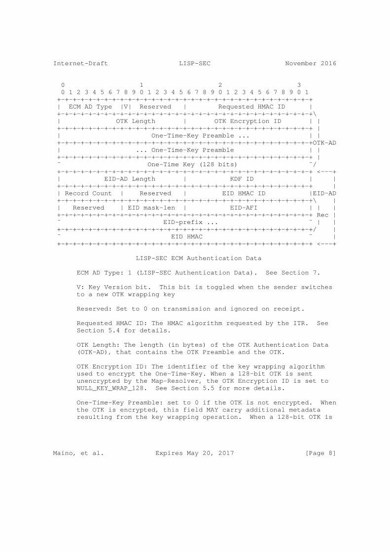
Internet-Draft LISP-SEC November 2016
0 1 2 3 0 1 2 3 4 5 6 7 8 9 0 1 2 3 4 5 6 7 8 9 0 1 2 3 4 5 6 7 8 9 0 1 +-+-+-+-+-+-+-+-+-+-+-+-+-+-+-+-+-+-+-+-+-+-+-+-+-+-+-+-+-+-+-+-+ | ECM AD Type |V| Reserved | Requested HMAC ID | +-+-+-+-+-+-+-+-+-+-+-+-+-+-+-+-+-+-+-+-+-+-+-+-+-+-+-+-+-+-+-+-+\ | OTK Length | OTK Encryption ID | | +-+-+-+-+-+-+-+-+-+-+-+-+-+-+-+-+-+-+-+-+-+-+-+-+-+-+-+-+-+-+-+-+ | | One-Time-Key Preamble ... | | +-+-+-+-+-+-+-+-+-+-+-+-+-+-+-+-+-+-+-+-+-+-+-+-+-+-+-+-+-+-+-+-+OTK-AD | ... One-Time-Key Preamble | | +-+-+-+-+-+-+-+-+-+-+-+-+-+-+-+-+-+-+-+-+-+-+-+-+-+-+-+-+-+-+-+-+ | ˜ One-Time Key (128 bits) ˜/ +-+-+-+-+-+-+-+-+-+-+-+-+-+-+-+-+-+-+-+-+-+-+-+-+-+-+-+-+-+-+-+-+ <---+ | EID-AD Length | KDF ID | | +-+-+-+-+-+-+-+-+-+-+-+-+-+-+-+-+-+-+-+-+-+-+-+-+-+-+-+-+-+-+-+-+ | | Record Count | Reserved | EID HMAC ID |EID-AD +-+-+-+-+-+-+-+-+-+-+-+-+-+-+-+-+-+-+-+-+-+-+-+-+-+-+-+-+-+-+-+-+\ | | Reserved | EID mask-len | EID-AFI | | | +-+-+-+-+-+-+-+-+-+-+-+-+-+-+-+-+-+-+-+-+-+-+-+-+-+-+-+-+-+-+-+-+ Rec | ˜ EID-prefix ... ˜ | | +-+-+-+-+-+-+-+-+-+-+-+-+-+-+-+-+-+-+-+-+-+-+-+-+-+-+-+-+-+-+-+-+/ | ˜ EID HMAC ˜ | +-+-+-+-+-+-+-+-+-+-+-+-+-+-+-+-+-+-+-+-+-+-+-+-+-+-+-+-+-+-+-+-+ <---+
LISP-SEC ECM Authentication Data
ECM AD Type: 1 (LISP-SEC Authentication Data). See Section 7.
V: Key Version bit. This bit is toggled when the sender switches to a new OTK wrapping key
Reserved: Set to 0 on transmission and ignored on receipt.
Requested HMAC ID: The HMAC algorithm requested by the ITR. See Section 5.4 for details.
OTK Length: The length (in bytes) of the OTK Authentication Data (OTK-AD), that contains the OTK Preamble and the OTK.
OTK Encryption ID: The identifier of the key wrapping algorithm used to encrypt the One-Time-Key. When a 128-bit OTK is sent unencrypted by the Map-Resolver, the OTK Encryption ID is set to NULL_KEY_WRAP_128. See Section 5.5 for more details.
One-Time-Key Preamble: set to 0 if the OTK is not encrypted. When the OTK is encrypted, this field MAY carry additional metadata resulting from the key wrapping operation. When a 128-bit OTK is
Maino, et al. Expires May 20, 2017 [Page 8]

Internet-Draft LISP-SEC November 2016
sent unencrypted by Map-Resolver, the OTK Preamble is set to 0x0000000000000000 (64 bits). See Section 5.5 for details.
One-Time-Key: the OTK encrypted (or not) as specified by OTK Encryption ID. See Section 5.5 for details.
EID-AD Length: length (in bytes) of the EID Authentication Data (EID-AD). The ITR MUST set EID-AD Length to 4 bytes, as it only fills the KDF ID field, and all the remaining fields part of the EID-AD are not present. An EID-AD MAY contain multiple EID- records. Each EID-record is 4-byte long plus the length of the AFI-encoded EID-prefix.
KDF ID: Identifier of the Key Derivation Function used to derive the MS-OTK. The ITR MAY use this field to indicate the recommended KDF algorithm, according to local policy. The Map- Server can overwrite the KDF ID if it does not support the KDF ID recommended by the ITR. See Section 5.4 for more details.
Record Count: The number of records in this Map-Request message. A record is comprised of the portion of the packet that is labeled ’Rec’ above and occurs the number of times equal to Record Count.
Reserved: Set to 0 on transmission and ignored on receipt.
EID HMAC ID: Identifier of the HMAC algorithm used to protect the integrity of the EID-AD. This field is filled by Map-Server that computed the EID-prefix HMAC. See Section 5.4 for more details.
EID mask-len: Mask length for EID-prefix.
EID-AFI: Address family of EID-prefix according to [RFC5226]
EID-prefix: The Map-Server uses this field to specify the EID- prefix that the destination ETR is authoritative for, and is the longest match for the requested EID.
EID HMAC: HMAC of the EID-AD computed and inserted by Map-Server. Before computing the HMAC operation the EID HMAC field MUST be set to 0. The HMAC covers the entire EID-AD.
5.2. Map-Reply LISP-SEC Extensions
LISP-SEC uses the Map-Reply defined in [RFC6830], with Type set to 2, and S bit set to 1 to indicate that the Map-Reply message includes Authentication Data (AD). The format of the LISP-SEC Map-Reply Authentication Data is defined in the following figure. PKT-AD is the Packet Authentication Data that covers the Map-Reply payload.
Maino, et al. Expires May 20, 2017 [Page 9]

Internet-Draft LISP-SEC November 2016
0 1 2 3 0 1 2 3 4 5 6 7 8 9 0 1 2 3 4 5 6 7 8 9 0 1 2 3 4 5 6 7 8 9 0 1 +-+-+-+-+-+-+-+-+-+-+-+-+-+-+-+-+-+-+-+-+-+-+-+-+-+-+-+-+-+-+-+-+ | MR AD Type | Reserved | +-+-+-+-+-+-+-+-+-+-+-+-+-+-+-+-+-+-+-+-+-+-+-+-+-+-+-+-+-+-+-+-+ <---+ | EID-AD Length | KDF ID | | +-+-+-+-+-+-+-+-+-+-+-+-+-+-+-+-+-+-+-+-+-+-+-+-+-+-+-+-+-+-+-+-+ | | Record Count | Reserved | EID HMAC ID |EID-AD +-+-+-+-+-+-+-+-+-+-+-+-+-+-+-+-+-+-+-+-+-+-+-+-+-+-+-+-+-+-+-+-+\ | | Reserved | EID mask-len | EID-AFI | | | +-+-+-+-+-+-+-+-+-+-+-+-+-+-+-+-+-+-+-+-+-+-+-+-+-+-+-+-+-+-+-+-+ Rec | ˜ EID-prefix ... ˜ | | +-+-+-+-+-+-+-+-+-+-+-+-+-+-+-+-+-+-+-+-+-+-+-+-+-+-+-+-+-+-+-+-+/ | ˜ EID HMAC ˜ | +-+-+-+-+-+-+-+-+-+-+-+-+-+-+-+-+-+-+-+-+-+-+-+-+-+-+-+-+-+-+-+-+ <---+ | PKT-AD Length | PKT HMAC ID |\ +-+-+-+-+-+-+-+-+-+-+-+-+-+-+-+-+-+-+-+-+-+-+-+-+-+-+-+-+-+-+-+-+ | ˜ PKT HMAC ˜PKT-AD +-+-+-+-+-+-+-+-+-+-+-+-+-+-+-+-+-+-+-+-+-+-+-+-+-+-+-+-+-+-+-+-+/
LISP-SEC Map-Reply Authentication Data
MR AD Type: 1 (LISP-SEC Authentication Data). See Section 7.
EID-AD Length: length (in bytes) of the EID-AD. An EID-AD MAY contain multiple EID-records. Each EID-record is 4-byte long plus the length of the AFI-encoded EID-prefix.
KDF ID: Identifier of the Key Derivation Function used to derive MS-OTK. See Section 5.7 for more details.
Record Count: The number of records in this Map-Reply message. A record is comprised of the portion of the packet that is labeled ’Rec’ above and occurs the number of times equal to Record Count.
Reserved: Set to 0 on transmission and ignored on receipt.
EID HMAC ID: Identifier of the HMAC algorithm used to protect the integrity of the EID-AD. See Section 5.7 for more details.
EID mask-len: Mask length for EID-prefix.
EID-AFI: Address family of EID-prefix according to [RFC5226].
EID-prefix: This field contains an EID-prefix that the destination ETR is authoritative for, and is the longest match for the requested EID.
Maino, et al. Expires May 20, 2017 [Page 10]

Internet-Draft LISP-SEC November 2016
EID HMAC: HMAC of the EID-AD, as computed by the Map-Server. Before computing the HMAC operation the EID HMAC field MUST be set to 0. The HMAC covers the entire EID-AD.
PKT-AD Length: length (in bytes) of the Packet Authentication Data (PKT-AD).
PKT HMAC ID: Identifier of the HMAC algorithm used to protect the integrity of the Map-reply.
PKT HMAC: HMAC of the whole Map-Reply packet, including the LISP- SEC Authentication Data. The scope of the authentication goes from the Map-Reply Type field to the PKT HMAC field included. Before computing the HMAC operation the PKT HMAC field MUST be set to 0. See Section 5.8 for more details.
5.3. Map-Register LISP-SEC Extentions
This memo is allocating one of the bits marked as Reserved in the Map-Register message defined in Section 6.1.6 of [RFC6830]. More precisely, the second bit after the Type field in a Map-Register message is allocated as the S bit. The S bit indicates to the Map- Server that the registering ETR is LISP-SEC enabled. An ETR that supports LISP-SEC MUST set the S bit in its Map-Register messages.
5.4. ITR Processing
Upon creating a Map-Request, the ITR generates a random ITR-OTK that is stored locally, together with the nonce generated as specified in [RFC6830].
The Map-Request MUST be encapsulated in an ECM, with the S-bit set to 1, to indicate the presence of Authentication Data. If the ITR and the Map-Resolver are configured with a shared key, the ITR-OTK confidentiality SHOULD be protected by wrapping the ITR-OTK with the algorithm specified by the OTK Encryption ID field. See Section 5.5 for further details on OTK encryption.
The Requested HMAC ID field contains the suggested HMAC algorithm to be used by the Map-Server and the ETR to protect the integrity of the ECM Authentication data and of the Map-Reply.
The KDF ID field specifies the suggested key derivation function to be used by the Map-Server to derive the MS-OTK. A KDF Value of NONE (0), MAY be used to specify that the ITR has no preferred KDF ID.
Maino, et al. Expires May 20, 2017 [Page 11]

Internet-Draft LISP-SEC November 2016
The EID-AD length is set to 4 bytes, since the Authentication Data does not contain EID-prefix Authentication Data, and the EID-AD contains only the KDF ID field.
In response to an encapsulated Map-Request that has the S-bit set, an ITR MUST receive a Map-Reply with the S-bit set, that includes an EID-AD and a PKT-AD. If the Map-Reply does not include both ADs, the ITR MUST discard it. In response to an encapsulated Map-Request with S-bit set to 0, the ITR expects a Map-Reply with S-bit set to 0, and the ITR SHOULD discard the Map-Reply if the S-bit is set.
Upon receiving a Map-Reply, the ITR must verify the integrity of both the EID-AD and the PKT-AD, and MUST discard the Map-Reply if one of the integrity checks fails.
The integrity of the EID-AD is verified using the locally stored ITR- OTK to re-compute the HMAC of the EID-AD using the algorithm specified in the EID HMAC ID field. If the EID HMAC ID field does not match the Requested HMAC ID the ITR SHOULD discard the Map-Reply and send, at the first opportunity it needs to, a new Map-Request with a different Requested HMAC ID field, according to ITR’s local policy. The scope of the HMAC operation covers the entire EID-AD, from the EID-AD Length field to the EID HMAC field, which must be set to 0 before the computation of the HMAC.
ITR MUST set the EID HMAC ID field to 0 before computing the HMAC.
To verify the integrity of the PKT-AD, first the MS-OTK is derived from the locally stored ITR-OTK using the algorithm specified in the KDF ID field. This is because the PKT-AD is generated by the ETR using the MS-OTK. If the KDF ID in the Map-Reply does not match the KDF ID requested in the Map-Request, the ITR SHOULD discard the Map- Reply and send, at the first opportunity it needs to, a new Map- Request with a different KDF ID, according to ITR’s local policy.
The derived MS-OTK is then used to re-compute the HMAC of the PKT-AD using the Algorithm specified in the PKT HMAC ID field. If the PKT HMAC ID field does not match the Requested HMAC ID the ITR SHOULD discard the Map-Reply and send, at the first opportunity it needs to, a new Map-Request with a different Requested HMAC ID according to ITR’s local policy or until all HMAC IDs supported by the ITR have been attempted.
Each individual Map-Reply EID-record is considered valid only if: (1) both EID-AD and PKT-AD are valid, and (2) the intersection of the EID-prefix in the Map-Reply EID-record with one of the EID-prefixes contained in the EID-AD is not empty. After identifying the Map- Reply record as valid, the ITR sets the EID-prefix in the Map-Reply
Maino, et al. Expires May 20, 2017 [Page 12]

Internet-Draft LISP-SEC November 2016
record to the value of the intersection set computed before, and adds the Map-Reply EID-record to its EID-to-RLOC cache, as described in [RFC6830]. An example of Map-Reply record validation is provided in Section 5.4.1.
The ITR SHOULD send SMR triggered Map-Requests over the mapping system in order to receive a secure Map-Reply. If an ITR accepts piggybacked Map-Replies, it SHOULD also send a Map-Request over the mapping system in order to verify the piggybacked Map-Reply with a secure Map-Reply.
5.4.1. Map-Reply Record Validation
The payload of a Map-Reply may contain multiple EID-records. The whole Map-Reply is signed by the ETR, with the PKT HMAC, to provide integrity protection and origin authentication to the EID-prefix records claimed by the ETR. The Authentication Data field of a Map- Reply may contain multiple EID-records in the EID-AD. The EID-AD is signed by the Map-Server, with the EID HMAC, to provide integrity protection and origin authentication to the EID-prefix records inserted by the Map-Server.
Upon receiving a Map-Reply with the S-bit set, the ITR first checks the validity of both the EID HMAC and of the PKT-AD HMAC. If either one of the HMACs is not valid, a log action MUST be taken and the Map-Reply MUST NOT be processed any further. If both HMACs are valid, the ITR proceeds with validating each individual EID-record claimed by the ETR by computing the intersection of each one of the EID-prefix contained in the payload of the Map-Reply with each one of the EID-prefixes contained in the EID-AD. An EID-record is valid only if at least one of the intersections is not the empty set.
For instance, the Map-Reply payload contains 3 mapping record EID- prefixes:
2001:db8:0102::/48
2001:db8:0103::/48
2001:db8:0200::/40
The EID-AD contains two EID-prefixes:
2001:db8:0103::/48
2001:db8:0203::/48
Maino, et al. Expires May 20, 2017 [Page 13]
Internet-Draft LISP-SEC November 2016
The EID-record with EID-prefix 2001:db8:0102::/48 is not eligible to be used by the ITR since it is not included in any of the EID-ADs signed by the Map-Server. A log action MUST be taken.
The EID-record with EID-prefix 2001:db8:0103::/48 is eligible to be used by the ITR because it matches the second EID-prefix contained in the EID-AD.
The EID-record with EID-prefix 2001:db8:0200::/40 is not eligible to be used by the ITR since it is not included in any of the EID-ADs signed by the Map-Server. A log action MUST be taken. In this last example the ETR is trying to over claim the EID-prefix 2001:db8:0200::/40, but the Map-Server authorized only 2001:db8:0203::/48, hence the EID-record is discarded.
5.4.2. PITR Processing
The processing performed by a PITR is equivalent to the processing of an ITR. However, if the PITR is directly connected to a Mapping System such as LISP+ALT [RFC6836], the PITR performs the functions of both the ITR and the Map-Resolver forwarding the Map-Request encapsulated in an ECM header that includes the Authentication Data fields as described in Section 5.6.
5.5. Encrypting and Decrypting an OTK
MS-OTK confidentiality is required in the path between the Map-Server and the ETR, the MS-OTK SHOULD be encrypted using the preconfigured key shared between the Map-Server and the ETR for the purpose of securing ETR registration [RFC6833]. Similarly, if ITR-OTK confidentiality is required in the path between the ITR and the Map- Resolver, the ITR-OTK SHOULD be encrypted with a key shared between the ITR and the Map-Resolver.
The OTK is encrypted using the algorithm specified in the OTK Encryption ID field. When the AES Key Wrap algorithm is used to encrypt a 128-bit OTK, according to [RFC3394], the AES Key Wrap Initialization Value MUST be set to 0xA6A6A6A6A6A6A6A6 (64 bits). The output of the AES Key Wrap operation is 192-bit long. The most significant 64-bit are copied in the One-Time Key Preamble field, while the 128 less significant bits are copied in the One-Time Key field of the LISP-SEC Authentication Data.
When decrypting an encrypted OTK the receiver MUST verify that the Initialization Value resulting from the AES Key Wrap decryption operation is equal to 0xA6A6A6A6A6A6A6A6. If this verification fails the receiver MUST discard the entire message.
Maino, et al. Expires May 20, 2017 [Page 14]

Internet-Draft LISP-SEC November 2016
When a 128-bit OTK is sent unencrypted the OTK Encryption ID is set to NULL_KEY_WRAP_128, and the OTK Preamble is set to 0x0000000000000000 (64 bits).
5.6. Map-Resolver Processing
Upon receiving an encapsulated Map-Request with the S-bit set, the Map-Resolver decapsulates the ECM message. The ITR-OTK, if encrypted, is decrypted as specified in Section 5.5.
Protecting the confidentiality of the ITR-OTK and, in general, the security of how the Map-Request is handed by the Map-Resolver to the Map-Server, is specific to the particular Mapping System used, and outside of the scope of this memo.
In Mapping Systems where the Map-Server is compliant with [RFC6833], the Map-Resolver originates a new ECM header with the S-bit set, that contains the unencrypted ITR-OTK, as specified in Section 5.5, and the other data derived from the ECM Authentication Data of the received encapsulated Map-Request.
The Map-Resolver then forwards to the Map-Server the received Map- Request, encapsulated in the new ECM header that includes the newly computed Authentication Data fields.
5.7. Map-Server Processing
Upon receiving an ECM encapsulated Map-Request with the S-bit set, the Map-Server process the Map-Request according to the value of the S-bit contained in the Map-Register sent by the ETR during registration.
If the S-bit contained in the Map-Register was clear the Map-Server decapsulates the ECM and generates a new ECM encapsulated Map-Request that does not contain an ECM Authentication Data, as specified in [RFC6830]. The Map-Server does not perform any further LISP-SEC processing, and the Map-Reply will not be protected.
If the S-bit contained in the Map-Register was set the Map-Server decapsulates the ECM and generates a new ECM Authentication Data. The Authentication Data includes the OTK-AD and the EID-AD, that contains EID-prefix authorization information, that are ultimately sent to the requesting ITR.
The Map-Server updates the OTK-AD by deriving a new OTK (MS-OTK) from the ITR-OTK received with the Map-Request. MS-OTK is derived applying the key derivation function specified in the KDF ID field. If the algorithm specified in the KDF ID field is not supported, the
Maino, et al. Expires May 20, 2017 [Page 15]

Internet-Draft LISP-SEC November 2016
Map-Server uses a different algorithm to derive the key and updates the KDF ID field accordingly.
The Map-Server and the ETR MUST be configured with a shared key for mapping registration according to [RFC6833]. If MS-OTK confidentiality is required, then the MS-OTK SHOULD be encrypted, by wrapping the MS-OTK with the algorithm specified by the OTK Encryption ID field as specified in Section 5.5.
The Map-Server includes in the EID-AD the longest match registered EID-prefix for the destination EID, and an HMAC of this EID-prefix. The HMAC is keyed with the ITR-OTK contained in the received ECM Authentication Data, and the HMAC algorithm is chosen according to the Requested HMAC ID field. If The Map-Server does not support this algorithm, the Map-Server uses a different algorithm and specifies it in the EID HMAC ID field. The scope of the HMAC operation covers the entire EID-AD, from the EID-AD Length field to the EID HMAC field, which must be set to 0 before the computation.
The Map-Server then forwards the updated ECM encapsulated Map- Request, that contains the OTK-AD, the EID-AD, and the received Map- Request to an authoritative ETR as specified in [RFC6830].
5.7.1. Map-Server Processing in Proxy mode
If the Map-Server is in proxy mode, it generates a Map-Reply, as specified in [RFC6830], with the S-bit set to 1. The Map-Reply includes the Authentication Data that contains the EID-AD, computed as specified in Section 5.7, as well as the PKT-AD computed as specified in Section 5.8.
5.8. ETR Processing
Upon receiving an ECM encapsulated Map-Request with the S-bit set, the ETR decapsulates the ECM message. The OTK field, if encrypted, is decrypted as specified in Section 5.5 to obtain the unencrypted MS-OTK.
The ETR then generates a Map-Reply as specified in [RFC6830] and includes the Authentication Data that contains the EID-AD, as received in the encapsulated Map-Request, as well as the PKT-AD.
The EID-AD is copied from the Authentication Data of the received encapsulated Map-Request.
The PKT-AD contains the HMAC of the whole Map-Reply packet, keyed with the MS-OTK and computed using the HMAC algorithm specified in the Requested HMAC ID field of the received encapsulated Map-Request.
Maino, et al. Expires May 20, 2017 [Page 16]
Internet-Draft LISP-SEC November 2016
If the ETR does not support the Requested HMAC ID, it uses a different algorithm and updates the PKT HMAC ID field accordingly. The scope of the HMAC operation covers the entire PKT-AD, from the Map-Reply Type field to the PKT HMAC field, which must be set to 0 before the computation.
Finally the ETR sends the Map-Reply to the requesting ITR as specified in [RFC6830].
6. Security Considerations
6.1. Mapping System Security
The LISP-SEC threat model described in Section 3, assumes that the LISP Mapping System is working properly and eventually delivers Map- Request messages to a Map-Server that is authoritative for the requested EID.
It is assumed that the Mapping System ensures the confidentiality of the OTK, and the integrity of the Map-Reply data. However, how the LISP Mapping System is secured is out of the scope of this document.
Similarly, Map-Register security, including the right for a LISP entity to register an EID-prefix or to claim presence at an RLOC, is out of the scope of LISP-SEC.
6.2. Random Number Generation
The ITR-OTK MUST be generated by a properly seeded pseudo-random (or strong random) source. See [RFC4086] for advice on generating security-sensitive random data
6.3. Map-Server and ETR Colocation
If the Map-Server and the ETR are colocated, LISP-SEC does not provide protection from overclaiming attacks mounted by the ETR. However, in this particular case, since the ETR is within the trust boundaries of the Map-Server, ETR’s overclaiming attacks are not included in the threat model.
6.4. Deploying LISP-SEC
This memo is written according to [RFC2119]. Specifically, the use of the key word SHOULD "or the adjective ’RECOMMENDED’, mean that there may exist valid reasons in particular circumstances to ignore a particular item, but the full implications must be understood and carefully weighed before choosing a different course".
Maino, et al. Expires May 20, 2017 [Page 17]

Internet-Draft LISP-SEC November 2016
Those deploying LISP-SEC according to this memo, should carefully weight how the LISP-SEC threat model applies to their particular use case or deployment. If they decide to ignore a particular recommendation, they should make sure the risk associated with the corresponding threats is well understood.
As an example, in certain closed and controlled deployments, it is possible that the threat associated with a MiTM between the xTR and the Mapping System is very low, and after carfeul consideration it may be decided to allow a NULL key wrapping algorithm while carrying the OTKs between the xTR and the Mapping System.
As an example at the other end of the spectrum, in certain other deployments, attackers may be very sophisticated, and force the deployers to enforce very strict policies in term of HMAC algorithms accepted by an ITR.
Similar considerations apply to the entire LISP-SEC threat model, and should guide the deployers and implementors whenever they encounter the key word SHOULD across this memo.
7. IANA Considerations
7.1. ECM AD Type Registry
IANA is requested to create the "ECM Authentication Data Type" registry with values 0-255, for use in the ECM LISP-SEC Extensions Section 5.1. The registry MUST be initially populated with the following values:
Name Value Defined In ------------------------------------------------- Reserved 0 This memo LISP-SEC-ECM-EXT 1 This memo
HMAC Functions
Values 2-255 are unassigned. They are to be assigned according to the "Specification Required" policy defined in [RFC5226].
7.2. Map-Reply AD Type Registry
IANA is requested to create the "Map-Reply Authentication Data Type" registry with values 0-255, for use in the Map-Reply LISP-SEC Extensions Section 5.2. The registry MUST be initially populated with the following values:
Maino, et al. Expires May 20, 2017 [Page 18]
Internet-Draft LISP-SEC November 2016
Name Value Defined In ------------------------------------------------- Reserved 0 This memo LISP-SEC-MR-EXT 1 This memo
HMAC Functions
Values 2-255 are unassigned. They are to be assigned according to the "Specification Required" policy defined in [RFC5226].
7.3. HMAC Functions
IANA is requested to create the "LISP-SEC Authentication Data HMAC ID" registry with values 0-65535 for use as Requested HMAC ID, EID HMAC ID, and PKT HMAC ID in the LISP-SEC Authentication Data:
Name Number Defined In ------------------------------------------------- NONE 0 This memo AUTH-HMAC-SHA-1-96 1 [RFC2104] AUTH-HMAC-SHA-256-128 2 [RFC6234]
HMAC Functions
Values 3-65535 are unassigned. They are to be assigned according to the "Specification Required" policy defined in [RFC5226].
AUTH-HMAC-SHA-1-96 MUST be supported, AUTH-HMAC-SHA-256-128 SHOULD be supported.
7.4. Key Wrap Functions
IANA is requested to create the "LISP-SEC Authentication Data Key Wrap ID" registry with values 0-65535 for use as OTK key wrap algorithms ID in the LISP-SEC Authentication Data:
Name Number Defined In ------------------------------------------------- Reserved 0 This memo NULL-KEY-WRAP-128 1 This memo AES-KEY-WRAP-128 2 [RFC3394]
Key Wrap Functions
Maino, et al. Expires May 20, 2017 [Page 19]

Internet-Draft LISP-SEC November 2016
Values 3-65535 are unassigned. They are to be assigned according to the "Specification Required" policy defined in [RFC5226].
NULL-KEY-WRAP-128, and AES-KEY-WRAP-128 MUST be supported.
NULL-KEY-WRAP-128 is used to carry an unencrypted 128-bit OTK, with a 64-bit preamble set to 0x0000000000000000 (64 bits).
7.5. Key Derivation Functions
IANA is requested to create the "LISP-SEC Authentication Data Key Derivation Function ID" registry with values 0-65535 for use as KDF ID in the LISP-SEC Authentication Data:
Name Number Defined In ------------------------------------------------- NONE 0 This memo HKDF-SHA1-128 1 [RFC5869]
Key Derivation Functions
Values 2-65535 are unassigned. They are to be assigned according to the "Specification Required" policy defined in [RFC5226].
HKDF-SHA1-128 MUST be supported
8. Acknowledgements
The authors would like to acknowledge Pere Monclus, Dave Meyer, Dino Farinacci, Brian Weis, David McGrew, Darrel Lewis and Landon Curt Noll for their valuable suggestions provided during the preparation of this document.
9. Normative References
[RFC2104] Krawczyk, H., Bellare, M., and R. Canetti, "HMAC: Keyed- Hashing for Message Authentication", RFC 2104, DOI 10.17487/RFC2104, February 1997, <http://www.rfc-editor.org/info/rfc2104>.
[RFC2119] Bradner, S., "Key words for use in RFCs to Indicate Requirement Levels", BCP 14, RFC 2119, DOI 10.17487/RFC2119, March 1997, <http://www.rfc-editor.org/info/rfc2119>.
Maino, et al. Expires May 20, 2017 [Page 20]
Internet-Draft LISP-SEC November 2016
[RFC3394] Schaad, J. and R. Housley, "Advanced Encryption Standard (AES) Key Wrap Algorithm", RFC 3394, DOI 10.17487/RFC3394, September 2002, <http://www.rfc-editor.org/info/rfc3394>.
[RFC4086] Eastlake 3rd, D., Schiller, J., and S. Crocker, "Randomness Requirements for Security", BCP 106, RFC 4086, DOI 10.17487/RFC4086, June 2005, <http://www.rfc-editor.org/info/rfc4086>.
[RFC5226] Narten, T. and H. Alvestrand, "Guidelines for Writing an IANA Considerations Section in RFCs", BCP 26, RFC 5226, DOI 10.17487/RFC5226, May 2008, <http://www.rfc-editor.org/info/rfc5226>.
[RFC5869] Krawczyk, H. and P. Eronen, "HMAC-based Extract-and-Expand Key Derivation Function (HKDF)", RFC 5869, DOI 10.17487/RFC5869, May 2010, <http://www.rfc-editor.org/info/rfc5869>.
[RFC6234] Eastlake 3rd, D. and T. Hansen, "US Secure Hash Algorithms (SHA and SHA-based HMAC and HKDF)", RFC 6234, DOI 10.17487/RFC6234, May 2011, <http://www.rfc-editor.org/info/rfc6234>.
[RFC6830] Farinacci, D., Fuller, V., Meyer, D., and D. Lewis, "The Locator/ID Separation Protocol (LISP)", RFC 6830, DOI 10.17487/RFC6830, January 2013, <http://www.rfc-editor.org/info/rfc6830>.
[RFC6833] Fuller, V. and D. Farinacci, "Locator/ID Separation Protocol (LISP) Map-Server Interface", RFC 6833, DOI 10.17487/RFC6833, January 2013, <http://www.rfc-editor.org/info/rfc6833>.
[RFC6836] Fuller, V., Farinacci, D., Meyer, D., and D. Lewis, "Locator/ID Separation Protocol Alternative Logical Topology (LISP+ALT)", RFC 6836, DOI 10.17487/RFC6836, January 2013, <http://www.rfc-editor.org/info/rfc6836>.
[RFC7835] Saucez, D., Iannone, L., and O. Bonaventure, "Locator/ID Separation Protocol (LISP) Threat Analysis", RFC 7835, DOI 10.17487/RFC7835, April 2016, <http://www.rfc-editor.org/info/rfc7835>.
Maino, et al. Expires May 20, 2017 [Page 21]

Internet-Draft LISP-SEC November 2016
Authors’ Addresses
Fabio Maino Cisco Systems 170 Tasman Drive San Jose, California 95134 USA
Email: [email protected]
Vina Ermagan Cisco Systems 170 Tasman Drive San Jose, California 95134 USA
Email: [email protected]
Albert Cabellos Technical University of Catalonia c/ Jordi Girona s/n Barcelona 08034 Spain
Email: [email protected]
Damien Saucez INRIA 2004 route des Lucioles - BP 93 Sophia Antipolis France
Email: [email protected]
Maino, et al. Expires May 20, 2017 [Page 22]

Network Working Group P. Pillay-Esnault, Ed.Internet-Draft HuaweiIntended status: Informational D. FarinacciExpires: March 18, 2017 lispers.net D. Meyer Brocade D. Lake Cisco Systems T. Herbert Facebook M. Menthe University of Tuebingen D. Raychaudhuri Rutgers University J. Mueller ATT September 14, 2016
Problem Statement for Mapping Systems in Identity Enabled Networks draft-padma-ideas-problem-statement-00
Abstract
This document provides a brief overview of Identity Enabled Networks (IDEAS) and discusses the need for a standardized network mapping system that is scalable, robust and flexible for future networks. This memo also identifies several key areas that should be investigated for the architecture design of these network mapping systems and their protocol interfaces.
Status of This Memo
This Internet-Draft is submitted in full conformance with the provisions of BCP 78 and BCP 79.
Internet-Drafts are working documents of the Internet Engineering Task Force (IETF). Note that other groups may also distribute working documents as Internet-Drafts. The list of current Internet- Drafts is at http://datatracker.ietf.org/drafts/current/.
Internet-Drafts are draft documents valid for a maximum of six months and may be updated, replaced, or obsoleted by other documents at any time. It is inappropriate to use Internet-Drafts as reference material or to cite them other than as "work in progress."
This Internet-Draft will expire on March 18, 2017.
Pillay-Esnault, et al. Expires March 18, 2017 [Page 1]

Internet-Draft September 2016
Copyright Notice
Copyright (c) 2016 IETF Trust and the persons identified as the document authors. All rights reserved.
This document is subject to BCP 78 and the IETF Trust’s Legal Provisions Relating to IETF Documents (http://trustee.ietf.org/license-info) in effect on the date of publication of this document. Please review these documents carefully, as they describe your rights and restrictions with respect to this document. Code Components extracted from this document must include Simplified BSD License text as described in Section 4.e of the Trust Legal Provisions and are provided without warranty as described in the Simplified BSD License.
Table of Contents
1. Introduction . . . . . . . . . . . . . . . . . . . . . . . . 3 2. Specification of Requirements . . . . . . . . . . . . . . . . 4 3. Definition of Terms . . . . . . . . . . . . . . . . . . . . . 4 4. Problem Statement for Network Mapping Systems (NMS) . . . . . 5 4.1. The Need for a Common Control Plane Infrastructure . . . 5 4.2. Flexible, Open and Efficient Mapping System Interfaces . 5 4.3. Identifier Structure and Life Span . . . . . . . . . . . 5 4.4. Confidentiality . . . . . . . . . . . . . . . . . . . . . 6 4.5. Security . . . . . . . . . . . . . . . . . . . . . . . . 6 4.6. Automatic Bootstrapping . . . . . . . . . . . . . . . . . 6 5. Impact of ID Characteristics on Mapping Systems . . . . . . . 6 5.1. Identifier Allocation . . . . . . . . . . . . . . . . . . 8 5.2. Identifier Groups, Range and Scope . . . . . . . . . . . 9 6. Network Mapping System (NMS) Requirements . . . . . . . . . . 9 6.1. Mapping Responsibility . . . . . . . . . . . . . . . . . 9 6.2. Distribution and Redundancy . . . . . . . . . . . . . . . 10 6.3. Scale and Performance . . . . . . . . . . . . . . . . . . 10 6.4. Mapping System Security . . . . . . . . . . . . . . . . . 10 6.5. Flexibility for Next Generation Apps . . . . . . . . . . 11 7. Use Cases . . . . . . . . . . . . . . . . . . . . . . . . . . 11 7.1. Mobility . . . . . . . . . . . . . . . . . . . . . . . . 11 7.1.1. Mobility within a single provider network . . . . . . 12 7.1.2. Mobility between Provider Networks . . . . . . . . . 14 7.1.3. Mobility of a Subnet . . . . . . . . . . . . . . . . 16 7.1.4. Transport Layer Mobility . . . . . . . . . . . . . . 17 7.2. Session Continuity in Heterogeneous Multi-Access Environments . . . . . . . . . . . . . . . . . . . . . . 18 7.2.1. Dynamic Mobility across Heterogeneous Access Networks 18 7.2.2. Multi-network Access Support . . . . . . . . . . . . 19 7.2.3. Late Binding Capability . . . . . . . . . . . . . . . 19 7.2.4. Disconnection-tolerant routing . . . . . . . . . . . 20
Pillay-Esnault, et al. Expires March 18, 2017 [Page 2]

Internet-Draft September 2016
7.3. Cross-Silo Communication . . . . . . . . . . . . . . . . 20 7.4. Network simplification . . . . . . . . . . . . . . . . . 21 7.5. Ease of Provisioning . . . . . . . . . . . . . . . . . . 22 8. Security Considerations . . . . . . . . . . . . . . . . . . . 23 9. IANA Considerations . . . . . . . . . . . . . . . . . . . . . 23 10. Contributors . . . . . . . . . . . . . . . . . . . . . . . . 23 11. Acknowledgments . . . . . . . . . . . . . . . . . . . . . . . 23 12. References . . . . . . . . . . . . . . . . . . . . . . . . . 23 12.1. Normative References . . . . . . . . . . . . . . . . . . 23 12.2. Informative References . . . . . . . . . . . . . . . . . 24 Authors’ Addresses . . . . . . . . . . . . . . . . . . . . . . . 24
1. Introduction
The current Internet architecture with Internet Protocol (IP) was designed for a very different environment from today’s networks. The October 2006 IAB Routing and Addressing Workshop [RFC4984] identified several future trends in Section 5 and foreseeable problems in Section 7. As predicted, the number of users using mobile devices has exploded over the years. While mobility and security were identified as concerns in the report they were not the primary focus. Fast-forward 10 years, mobility security, and hyper-connectivity with IoT have now emerged as major challenges for the network infrastructure. This document proposes to compile a concise problem statement and use cases as an input for future work.
Internet Protocols were originally designed for fixed networks. At the time, the size of the headers was a concern and the solution adopted was to overload the IP address semantic by using it to define both the identifier(ID) and location (LOC) of an entity . A side- effect of this optimization was that session continuity with TCP/IP would require retaining the same IP addresses at both endpoints across a movement. [RFC4984] suggests that a generic identifier- locator separation would be a possible solution to support billions of mobile gadgets without "bringing undue impact on global routing scalability and stability". Multiple mobility solutions have been explored and among them the identifier-based solutions such as Host Identity Protocol (HIP) [RFC7401], Location Identifier Separation Protocol (LISP) [RFC6830], Identifier Locator Network Protocol [RFC6740], and Identifier Locator Addressing[ILA]. The basic premise behind these solutions was to make changes of location transparent to the upper layers above including TCP/IP. The technique used to mask the change of location to higher layers was to decouple the identifier and location.
With the hyper-connectivity and scale expected in 2020, the static Internet architecture is an added constraint to build robust, efficient, simple, flexible and scalable solutions. The decoupling
Pillay-Esnault, et al. Expires March 18, 2017 [Page 3]

Internet-Draft September 2016
of ID and LOC will enable newer breeds of applications with integrated security and privacy without expectations to be tethered to any fixed point. While Identity Enabled Networks have often been associated with mobility, the latter is just one of the many use cases of ID Enabled networks. Section 7 of this document describes others.
2. Specification of Requirements
The key words "MUST", "MUST NOT", "REQUIRED", "SHALL", "SHALL NOT", "SHOULD", "SHOULD NOT", "RECOMMENDED", "MAY", and "OPTIONAL" in this document are to be interpreted as described in [RFC2119].
3. Definition of Terms
Entity: An entity can be a device, node or a process, which need to be identified in a network. An entity can also be a collection of entities, for example a multicast group, or an ad-hoc vehicular network that needs to be uniquely identified. An entity can have one or multiple identifiers to identify it.
Identifier (ID): An identifier is a name which can be used to identify an entity unambiguously within a scope.
Locator (LOC): A locator is a routable address in a network. It is used for reachability to an entity.
Identity Enabled Networks (IDEAS): Identity Enabled Networks are networks that support the identifier and location decoupling. The reachability to an entity is achieved by mapping its identifier(s) to a location.
Identifier-based or ID-based: A protocol or a solution is ID-based if they use an ID-LOC decoupling and a Mapping system as base architecture.
Identity-aware or ID-aware: An application is ID-aware if it makes use of the Identifier of an entity to establish communication.
Network Mapping Systems (NMS): A network mapping system is a network database that stores the ID and the associated LOC(s). It may also contain metadata specific to the ID.
Binding: The process of binding an ID to its associated LOC(s), based on a lookup/query of the NMS.
5G: Fifth Generation mobile networks.
Pillay-Esnault, et al. Expires March 18, 2017 [Page 4]

Internet-Draft September 2016
4. Problem Statement for Network Mapping Systems (NMS)
4.1. The Need for a Common Control Plane Infrastructure
Today, most locator/identifier separation solutions rely on a mapping system control plane that maps an ID to one or multiple locators. Currently, these solutions implements their own mapping system. The mapping system may leverage push-based protocols (traditional routing protocols), pull based control-planes (Domain Name Service and LISP), or Software Defined Network (SDN) controllers. The ID-based protocols can be considered to provide efficient solutions for mobility and the Internet of Things.
While many ID-enabled data plane mechanisms serve fundamentally different objectives and do not need to interoperate there is a potential benefit in providing them a common mapping interface. A common mapping system infrastructure may facilitate cross-platform synergy. Furthermore, the lack of a standardized mapping system will be an impediment for the deployment of ID-enabled solutions and a high diversity of mapping system variants will create silos that are expensive to maintain both from a CAPEX and OPEX point of view.
In addition, future ID-aware application spanning over multiple ID- based protocols will have a huge complexity at application level
4.2. Flexible, Open and Efficient Mapping System Interfaces
Newer ID-aware applications or ID-based protocols will define their own ID allocation scheme and mapping if they do not need compatibility or operability with today’s systems. Therefore, the mapping system must be flexible and extensible towards novel ID and mapping types. Furthermore, mapping resolution must be fast to support low delay requirements of future communication.
4.3. Identifier Structure and Life Span
Currently, there is no guidance or allocation scheme for public IDs. Furthermore, the ID format varies by protocol. An agreed upon ID format and scope may facilitate interoperability and simplify the implementation of some use cases. The administrative boundaries are a reflection of how the world is connected and ease of deployment should become an inherent requirement in recommendations for the allocation of IDs.
Many entities are expected to have a "life span", therefore, recycling their IDs seems a valid desire. However, the IPv6 address space is huge (2^128 ˜ 10^38) and will suffice for a long time even
Pillay-Esnault, et al. Expires March 18, 2017 [Page 5]
Internet-Draft September 2016
without recycling. Thus, at this time, the requirements for recycling of IDs is beyond the scope of this document.
4.4. Confidentiality
The access to a mapping system may reveal the location of an ID and therefore any breach is considered a security risk. In the future it would be best to use standardized methods or recommendations for secured access to mapping systems.
4.5. Security
In the current Internet architecture, each network-connected device must establish a TCP/IP connection, before a client can perform authentication. During a cyber attack vulnerability scanning tools are able to identify what network applications are present and, in many cases, develop signatures of the network-connected devices, which includes the operating system, network applications, and their release and patch levels. This information can then be used to develop strategies to attack the network-connected device. However, a mechanism that requires authentication before establishing a TCP/ IP, closes this security hole and denies attackers information.
In identity enabled networks, an initial authentication of the ID related to the network-connected device is performed before a session is established. This may block a cyber-attack before the connection is established and reduces the burden of deep packet inspection and the consequent overhead and latency.
4.6. Automatic Bootstrapping
Automatic bootstrapping is required in advanced communication because the diversity of communication will be so massive that a user cannot be expected to cope with the configuration of each and every application. 5G, IoT, and machine-to-machine (M2M) communication are just emerging examples. In the future, it is highly desirable that there should be minimal or Zero Touch Provisioning (ZTP) on new devices coming online. Automatic bootstrapping is particularly pertinent for the industrial Internet where M2M is expected to be functional with minimum human intervention. The ease of provisioning use case is described in the Section 7 of this document.
5. Impact of ID Characteristics on Mapping Systems
ID may have multiple characteristics. The table below attempts to capture some of their pros and cons.
Pillay-Esnault, et al. Expires March 18, 2017 [Page 6]

Internet-Draft September 2016
+----------------+----------------+-------------------+-------------+ | Characteristics| Pros Technical | Pros Non-technical| Cons | +----------------+----------------+-------------------+-------------+ | Large Name |Need to account | Scalable | Very large | | Space |for billions of | | space | | |devices,Scalable| | Unmanageable| +----------------+----------------+-------------------+-------------+ | Global ID |Easier to create| Requires access | Location | | |a unique mapping| to mapping | is known | | |service | services | to all | | |Uniqueness | | Lack of | | | | | privacy | | | | User identifies | Security | | | | easily with ID | Risk | | | | (e.g. phone #) | | +----------------+----------------+-------------------+-------------+ | Multiple ID |Allows multiple | Privacy, some can | Complexity | | |identities. | be ephemeral | | | |Poss. multiple | or not | | | |class of service| | | +----------------+----------------+-------------------+-------------+ | Mappable |Backward | Cost Effective. | | | Translatable |compatible with | | | | to IP |existing apps | No change of base | | | | | infrastructure | | +----------------+----------------+-------------------+-------------+ | Variable Length| Backward | Cost Effective. |Implementa- | | | compatible with| |tion cost | | | existing apps | Can work with | | | | | IPv4, ipv6 and | | | | | as non-ip | | +----------------+----------------+-------------------+-------------+ | Non-Encrypted | | Ease of use and | Security | | | | troubleshooting | Risk | +----------------+----------------+-------------------+-------------+ | Encrypted | Security | | Not Human | | | | | Readable | | | | | hard to use | +----------------+----------------+-------------------+-------------+ | Human | | Human Manageable | Security | | Readable | | Ease of use | Risk | +----------------+----------------+-------------------+-------------+ | Hierarchical | Easier to | Easy Assignment | Need ID | | | look up | | Structure ID| | | | | Lack of | | | | | Privacy, | +----------------+----------------+-------------------+-------------+ | Not | Need to ensure | Complete Freedom |May be harder|
Pillay-Esnault, et al. Expires March 18, 2017 [Page 7]

Internet-Draft September 2016
| Structured | no collision | |to manage | | | can use crypto | | look-up | | | key | | scale | +----------------+----------------+-------------------+-------------+ | Range | Easier to have | Administrative | Confident- | | or scope | hierarchy in |Domain | iality | | | mapping systems|control easier | | | | |Lawful Interception| | +----------------+----------------+-------------------+-------------+ | Geographical | Easier for | Admin Ctrl. | Privacy, | | Awareness | incremental | per AS or ISP. | Confident- | | | deployment | Policy possible | iality | | | | per admin Domain | Tracking | +----------------+----------------+-------------------+-------------+ | Provider | | | Locked in? | | Dependency | | | Migration | +----------------+----------------+-------------------+-------------+ | Structured | Distributed | Customization | Masquerading| | | systems that | services or apps | Misconfig | | | identifies | If name identifies| Maliciously | | | different types| types of objects. | Misrepresent| | | of devices | E.g. a Fridge | | | | -Mobile | is not mobile and | | | | -Home | belong to smart | | | | -Human ID | home | | | | -Ephemeral | | | | | Apps/Process | | | | | Slice | | | +----------------+----------------+-------------------+-------------+ | Context | Instantiation | Customization | Privacy | | Aware | | services or apps | Net | | | | based on ID aware | Neutrality | | | | Billing | | +----------------+----------------+-------------------+-------------+
Identifier pros and Cons
5.1. Identifier Allocation
Ideally, IDs should be unique and have an easy allocation scheme with minimal overhead for the administrators. It would be desirable to support public and private IDs for various use case requirements. A public ID may be visible to the external world or not. A private ID MUST still be unique in order to avoid issues during merges. IDs may be assigned automatically or administratively by configuration. For example, a mobile phone ID may be derived from its IMEI. Automatic ID allocation for an industrial robot coming online for the first time will be expected in industrial Internet. In contrast, other IDs
Pillay-Esnault, et al. Expires March 18, 2017 [Page 8]

Internet-Draft September 2016
may need to be assigned individually depending on the device (health monitoring).
5.2. Identifier Groups, Range and Scope
Currently, there are various types of IDs with different format and meaning across different protocols. If some entities have similar properties such as mobility scope, it may be desirable to allocate and manage them as a group, e.g., from the same "address" block" to enable aggregation. Grouping of IDs sharing the same fate as on a train or plane should also be possible. .
6. Network Mapping System (NMS) Requirements
6.1. Mapping Responsibility
The responsibility for the mapping may reside with the owner of the ID or the owner of the locator. Both approaches exist today.
In the DNS, authoritative servers belong to the owner of the DNS name space. In case of mobility, DNS names may be mapped to IP numbers of foreign networks.
In cellular communication systems, mobile phone user may roam into the area of another provider where its phone number is registered by the foreign mobile communication provider in the Visitor Location Register (VLR), i.e., the owner of the infrastructure takes care of the mapping. In case of a phone call, an entry in the Home Location Register (HLR) of the mobile communication provider refers to the foreign mobile communication provider. Given the fact that user stay most of the time within their country, roaming can be considered a rather rare event but that needs to be supported.
To facilitate scalability, mapping systems may be organized hierarchically, e.g., in terms of ID space or locator space which may reflect geography. The responsibility for the mapping may be assigned to an appropriated hierarchy level similarly to authoritative name servers in DNS.
For example, sensors networks may be part of a private space and limited scope and they would only communicate within a specialized application interface or gateway to the internet. In all these cases, it would be beneficial to have a regional allocation authority to manage them.
Pillay-Esnault, et al. Expires March 18, 2017 [Page 9]

Internet-Draft September 2016
6.2. Distribution and Redundancy
For any mapping system to be successful, it will need to be robust, distributed and provide redundancy. The mapping system design and architecture must avoid being single points of failure and MUST enforce resiliency.
6.3. Scale and Performance
A future mapping system will serve multiple applications requiring a vast number of entries. This requires high scalability and performance. Distribution, hierarchy, and aggregation may help to achieve these goals. However, fast query resolution is also an important objective to cope with the need for low latency. Therefore, the resolution mechanisms must be very efficient. Furthermore, mobility support requires that updates can be made simply, fast, and as needed. Last but not least, an ID should be able to be aggregated for scalability reasons, but the system should be flexible enough to disaggregate them if needed.
6.4. Mapping System Security
The secure mapping system must have the following requirements:
1. The components of the mapping system need to be robust against direct and indirect attacks. If any component is attacked, the rest of the system should act with integrity and scale and only the information associated with the compromised component is made unavailable.
2. The addition and removal of components of the mapping system must be performed in a secure matter so as to not violate the integrity and operation of the system and service it provides.
3. The information returned by components of the mapping system needs to be authenticated as to detect spoofing from masqueraders.
4. Information registered (by publishers) to the mapping system must be authenticated so the registering entity or the information is not spoofed.
5. The mapping system must allow request access (for subscribers) to be open and public. However, it is optional to provide confidentiality and authentication of the requesters and the information they are requesting.
Pillay-Esnault, et al. Expires March 18, 2017 [Page 10]

Internet-Draft September 2016
6. Any information provided by components of the mapping system must be cryptographically signed by the provider and verified by the consumer.
7. Message rate-limiting and other heuristics must be part of the foundational support of the mapping system to protect the system from invalid overloaded conditions.
8. The mapping system should support some form of provisioned policy. Either internal to the system or via mechanisms for users of the system to describe policy rules. Access control should not use traditional granular-based access lists since they do not scale and are hard to manage. By the use of token- or key- based authentication methods as well as deploying multiple instances of the mapping system will allow acceptable policy profiles. Machine learning techniques could automate these mechanisms.
6.5. Flexibility for Next Generation Apps
A mapping server could be a place to store metadata of interest that will facilitate deploying new capabilities such as context awareness in next generation applications and protocols. As always there are tradeoffs on the type of metadata stored and its usage. It is assumed that the metadata use is directly related to the use cases described in the document.
7. Use Cases
7.1. Mobility
This section considers some scenarios of mobility in Identity Enabled Networks. We assume that mobility should be seamless and transparent to the application and user as far as possible. In particular, TCP (transport) connections should remain functional across mobility events.
Seamless and transparent mobility in the network layer is achieved in Identity Enabled Networks by updating the mapping database to reflect changes.
From the perspective of user equipment (UE) (e.g.smartphone, automobile, airplane...) there are three common mobility scenarios:
- Mobility of nodes within a single provider network
- Mobility of nodes between provider networks
Pillay-Esnault, et al. Expires March 18, 2017 [Page 11]

Internet-Draft September 2016
- Mobility of subnet (within a provider network or between them)
7.1.1. Mobility within a single provider network
Figure 1 provides an example of the topology of a single mobile carrier network. UE.A, UE.B, and UE.C are devices connected to the mobile network and are themselves mobile. UE.A and UE.B are currently connected to base station Base1 and UE.C is currently connected to Base2. The base stations are connected to the radio access network (RAN) of the provider. The RAN is connected to the Internet via a mapping gateway (MGW). Host1 and Host2 are hosts in the Internet that are communicating with the UEs. In this example we assume that ID functionality is handled within the network and is transparent to the UEs or hosts.
+-------+ | UE.A |-----+ +-------+ | | +-------+ +-----+ +-----+ | UE.B |--|Base1|-----+ __________ +--|Host1| +-------+ +-----+ __|___ / \ | +-----+ / \ +-----+ ( )--+ ( RAN )--| MGW |-- ( Internet ) \_______/ +-----+ ( )--+ +-----+ | \__________/ | +-----+ |Base2|------+ +--|Host2| +-----+ +-----+ | +-------+ | | UE.C |-----+ +-------+
Pillay-Esnault, et al. Expires March 18, 2017 [Page 12]

Internet-Draft September 2016
+-------+ | UE.A |-----+ +-------+ | | +-------+ +-----+ +-----+ | UE.B |--|Base1|-----+ __________ +--|Host1| +-------+ +-----+ __|___ / \ | +-----+ / \ +-----+ ( )--+ ( RAN )--| MGW |-- ( Internet ) \_______/ +-----+ ( )--+ +-----+ | \__________/ | +-----+ |Base2|------+ +--|Host2| +-----+ +-----+ | +-------+ | | UE.C |-----+ +-------+
The role of the mapping gateway is to map destination addresses on ingress packets into the network to deliver packets to the destination. Mapping gateways maintain a list of identifiers to locator mappings. Hosts on the Internet only know the identifier of the mobile nodes, packets sent from the Internet are routed to a mapping gateway that is able to map the destination to a locator to facilitate delivery.
Consider that Host1 sends a packet to UE.A. The destination address of the packet is the identifier address of UE.A. The packet is sent by Host1 and is routed across the Internet to the provider’s network based on the identifier address. A mapping gateway receives the packet. The destination address of a packet (identifier) is looked up in the mapping table. The return result is the locator address for UE.A. The MGW modifies the packet so that the destination address is the locator for UE.A (either by encapsulation or address translation). The packet is then sent on the network and routed to Base1. At Base1 the destination is changed back to the identifier address and forwarded to the UE.
In the case that two UEs need to communicate the process is similar. Consider that UE.A sends a packet to UE.C. Again, UE.A only knows the identifier address of UE.C. UE.A sends a packet into the network and it is routed to a mapping gateway. The Mapping gateway maps the destination address of UE.C to its locator and forwards the packet to Base2 which translates the destination back to an identifier address.
In order to reduce latency and improve performance, a mapping cache may be implemented at or near the base stations. A mapping cache
Pillay-Esnault, et al. Expires March 18, 2017 [Page 13]

Internet-Draft September 2016
would maintain a subset of mappings in the network that are being used for communications by the attached UEs to other devices in the network. A protocol would be run between the base stations and mapping gateways to populate and invalidate entries in the cache.
Now consider that UE.B changes locations so that it is now attached to Base2 (figure 2).
+-------+ | UE.A |-----+ +-------+ | | +-----+ +-----+ |Base1|----+ __________ +--|Host1| +-----+ __|___ / \ | +-----+ | / \ +-----+ ( )--+ | ( RAN )--| MGW |-- ( Internet ) V \_______/ +-----+ ( )--+ +-------+ +-----+ | \__________/ | +-----+ | UE.B |--|Base2|-----+ +--|Host2| +-------+ +-----+ +-----+ | +-------+ | | UE.C |-----+ +-------+
The mapping gateways are updated to reflect UE.B’s new location. As updating location is not instantaneous across all the mapping gateways in the network, it is possible that a packet is routed to an old destination. For instance Base1 may receive packets for a UE.B after it has moved to Base2. A "care of address" could be set on Base1 for some period after the move. When Base1 receives a packet for UE.B it can map the destination address to reflect UE.B’s new location and forward the packet. Alternatively, a predictive algorithm can be used to forward packets ahead of the move.
7.1.2. Mobility between Provider Networks
Consider the example network topology in figure 3. In this case UE.A and UE.B are connected to one provider network and UE.C is connected to another. We assume that the UEs are respectively customers of these attached networks and that they are assigned identifiers from the pool of each carrier (their "home network"). In this configuration connectivity to the UEs is achieved as described above.
Pillay-Esnault, et al. Expires March 18, 2017 [Page 14]

Internet-Draft September 2016
+-------+ | UE.A |----+ +-------+ | ______ +-----+ | / \ +-----+ _______ +--|Host1| +-------+ +-----+ ( RAN )--| MGW |---/ \ | +-----+ | UE.B |--|Base1|----\_______/ +-----+ ( )---+ +-------+ +-----+ ______ ( Internet ) / \ +-----+ ( )---+ ( RAN )--| MGW |---\________/ | +-----+ \_______/ +-----+ +--|Host2| +-----+ | +-----+ |Base2|-------+ +-----+ | +-------+ | | UE.C |-----+ +-------+
When a UE moves between different carrier networks, the ID continues to work if the networks are able to share mapping information. Consider that UE.B moves to the other carrier network (figure 4).
+-------+ | UE.A |-----+ +-------+ | ______ +-----+ | / \ +-----+ _______ +--|Host1| +-----+ ( RAN )--| MGW |---/ \ | +-----+ |Base1|----\_______/ +-----+ ( )---+ +-----+ ______ ( Internet ) | / \ +-----+ ( )---+ | ( RAN )--| MGW |---\________/ | +-----+ V \_______/ +-----+ +--|Host2| +-------+ +-----+ | +-----+ | UE.B |--|Base2|-------+ +-------+ +-----+ | +-------+ | | UE.C |-----+ +-------+
Suppose Host1 sends a packet destined to UE.B. The identifier address for UE.B is set in the destination address of the packet. The packet is forwarded to the home network for UE.B since the identifier was assigned from that carrier’s pool. In order to handle
Pillay-Esnault, et al. Expires March 18, 2017 [Page 15]

Internet-Draft September 2016
this the packet can be mapped at the MGW to indicate the location of the current carrier network for UE.B. This can be done in at least two ways:
1. The new carrier provides the full locator (mapping to Base_station2) and the MGW sends directly to that locator
2. The packet is mapped so that it is routed to an MGW in the new network and that MGW in turn maps the packet to its final destination.
While #1 has the advantage of being more direct, it requires a higher rate of sharing mappings, for instance if UE.B moves to a new base station in the remote carrier network each change in the mapping would need to be propagated to the MGWs UE.B’s home network. In #2 movement within a remote network would be transparent to MGW in the home network.
7.1.3. Mobility of a Subnet
Figure 5 presents a topology where UE.A, UE.B, and UE.C are behind a subnet and the whole subnet may itself be mobile (for instance a WIFI network on a bus). To treat the subnet as an aggregate the subnet is reflected in the identifier address. A single mapping entry then could represent this subnet where the identifier is the prefix for the subnet and the locator reflects the location of the subnet (Base1 in this case)
+------+ | UE.A |--+ +------+ | +------+ | +-----+ +-----+ | UE.B |--+--|Base1|-----+ ________ +--|Host1| +------+ | +-----+ __|___ / \ | +-----+ +------+ | / \ +-----+ ( )--+ | UE.C |--+ ( RAN )--| MGW |-- ( Internet ) +------+ \_______/ +-----+ ( )--+ +-----+ | \________/ | +-----+ |Base2|-----+ +--|Host2| +-----+ +-----+
When the subnet moves the mappings to the identifier, the prefix for the subnet is updated in the MGWs (figure 6). Note that a UE could also move out of its subnet and attach to the network on its own, for instance a UE might switch from using Wi-Fi to using a mobile
Pillay-Esnault, et al. Expires March 18, 2017 [Page 16]

Internet-Draft September 2016
network. This will work if a specific mapping for UEs is allowed in the mapping database, and that mapping is preferred over the aggregate mapping since it has a longer identifier prefix.
| +-----+ +-----+ | |Base1|----+ ________ +--|Host1| V +-----+ __|___ / \ | +-----+ +-------+ / \ +-----+ ( )--+ | UE.A |--+ ( RAN )--| MGW |-- ( Internet ) +-------+ | \_______/ +-----+ ( )--+ +-------+ | +-----+ | \________/ | +-----+ | UE.B |--+--|Base2|-----+ +--|Host2| +-------+ | +-----+ +-----+ +-------+ | | UE.C |--+ +-------+
Similar to the case of a UE moving between carrier networks, a subnet can move between carrier networks if the networks share identifier locator mappings that include identifier prefixes.
7.1.4. Transport Layer Mobility
Identifier mobility, as described above, has the advantage that is it transparent to end hosts (UEs and hosts on the Internet). The disadvantage is that it is not supported in all networks and sharing mappings between carriers may be prohibitive or a least take a long time to be widely deployed. An alternative is to use a transport protocol that implements disassociated location, such as in QUIC and Transports over UDP (TOU).
When the location is decoupled, the transport layer endpoints no longer consider the IP addresses in identification. Instead a connection identifier is negotiated between two peers. The connection identifier is unique amongst all connections to a peer, so when a packet is presented with a connection identifier it can be used to unambiguously identify the connection and the peer regardless of what the source address is. Disassociated location works in tandem with strong encryption to prevent hijacking of connections. In this manner disassociated location allows mobility without losing connectivity.
Multi-path TCP (MPTCP) [RFC6182] is another alternative that allows TCP connections to be mobile. The downside of MPTCP is that the host
Pillay-Esnault, et al. Expires March 18, 2017 [Page 17]

Internet-Draft September 2016
needs to have insight into the underlying network topology in order to create multiple paths.
7.2. Session Continuity in Heterogeneous Multi-Access Environments
As the Internet is experiencing a transition from the fixed host- server model to one which mobile platforms are the norm, a next- generation protocol architecture, which provides integrated and efficient support for advanced host and network mobility services, becomes a necessity.
In terms of host mobility, the current mobile network architecture is unable to natively support session continuity. Intra-network mobility (mobility across a single access network) and inter-network mobility (mobility across heterogeneous access networks) are achieved through the usage of mobility anchors. These solutions generate problems like high latency, session disruptions (due to rerouting, triangular routing, unpredictable and sporadic disconnections and dynamic IP assignment) and lack of a common framework to inherently support mobility across heterogeneous access networks. In addition dynamic network formation and network mobility has limited support in the current Internet infrastructure.
Newer breeds of applications such as Augmented Reality, Virtual Reality, drone or robotic control have near real-time latency requirements below 10ms. On the other hand, multimedia streaming services (4k, 360-degree video) have real-time latency requirements in the range of ˜100ms. In addition, the very low latency (<5ms) higher bandwidth and speed expected in the 5g networks will be another challenge for solutions relying on buffering for continuity. The solutions based on mobility anchors and rerouting buffered data will not work efficiently for session continuity with very low latency requirements.
The principal requirements of the design of future networks for native support of mobility include dynamic mobility of end-hosts and networks across heterogeneous access networks, multi-network access support, late binding capability and disconnection-tolerant routing.
7.2.1. Dynamic Mobility across Heterogeneous Access Networks
As smartphones move across various mobility domains, their points of attachment to the Internet can change easily and rapidly. The need for supporting mobility arises when an individual node or a group of nodes move and reconnect to the Internet.
Frequent disconnections and IP address change on re-association to new access points interrupt the data transmission sessions.
Pillay-Esnault, et al. Expires March 18, 2017 [Page 18]
Internet-Draft September 2016
Solutions like transparent handover between base stations in cellular networks, which let users retain their static IP address, are practical only for intra-network mobility.
Furthermore, there are opportunities for a network to be formed between groups of vehicles on the highway, and these networks should be able to quickly peer along the edge with different networks encountered during mobility. As another emerging use-case consider Google’s Project Loon, which proposes to beam LTE access in developing countries from a network of aerial balloons.
Managing a global scale of unmanned and highly mobile base-stations is challenging, despite the partial solution that BGP currently provides for airline connectivity. Decoupling identity from location provides inherent support for mobility, provided the mapping system is scalable and supports fast query and lookup latencies. Optimizations such as "late binding", in which identity of in-transit packets can be bound to a locator closer to the edge of the network to account for highly mobile vehicular scenarios can be further developed based on the mapping system.
7.2.2. Multi-network Access Support
A typical mobile hand-held device can see multiple available networks at the same time. Although the majority of current business models generally restrict a user to a single cellular network provider, with the increasing popularity of "hetnet" mobile services, mobile device might be soon able to simultaneously connect to a dynamically changing set of cellular, WiFi and future 5G networks.
It is possible to consider a variety of service objectives for this scenario, ranging from "most economical" to "highest throughput interface" to "all interfaces".
End-to-end solutions to support multi-path connectivity do exist, but supporting network-wide multi-homing has a very broad architectural implication. This implication stems from having more fine-grained control over network resources, complete information regarding routing path quality and load conditions and more adaptive response to congestion/loss. Since these networks will in general be in different Internet domains, autonomous systems need to support independent paths of connectivity for a single end-to-end flow.
7.2.3. Late Binding Capability
Late binding refers to rebinding of identifiers to addresses after a packet enters the network. This capability makes it possible for routers in the network to redirect packets whose end-point address
Pillay-Esnault, et al. Expires March 18, 2017 [Page 19]

Internet-Draft September 2016
might have changed due to fast mobility or rapid changes in radio link association or multicast group membership.
This type of dynamic rerouting can help to improve network efficiency and reduce packet drops. Late binding generally requires in-network elements such as routers and base stations to be able to store data packets temporarily and access the ID to address mapping (name resolution) service.
7.2.4. Disconnection-tolerant routing
While disconnection-tolerant (DTN) routing has been principally considered for ad-hoc disaster-relief, vehicular and tactical network scenarios, temporary disconnections during mobility also require support for store and forward capabilities of DTN.
Session-oriented transport protocols like TCP reacts adversely to disconnections and has a slow re-connection and end-to-end setup delays, whereas unreliable protocols like UDP simply drops packets on disconnection. Having in-network routers store in-transit packets while allowing a "rebinding" of identity to location would improve end-to-end transport and enable newer mobility-centric transport protocols for 5G.
7.3. Cross-Silo Communication
The IoT landscape is comprised of many devices and protocols. Often, protocols are chosen due to constraints in the solution - for example a small CPU/Memory footprint does not allow for the formation of IPv6 packets or the battery-operated nature of the device is not compatible with the "always-reachable" nature of an IP stack.
There is little commonality and almost no interoperability between IoT consumer devices and many rely on their own network implementation. The use of gateways within IoT solution is common; areas which have several IoT solutions for different applications will often have more than one gateway. The common point is usually at the conventional IP network CPE device.
Whilst such an approach has allowed for rapid innovation in terms of IoT applications, the ability to harness the data within an entire domain and share it between different applications to generate results-based outcomes is more complex to achieve where data remains in silo-ed networks.
However, it has to be realized that consolidating a vast array of IoT datasets to a single, common form is likely to be unachievable without compromising the quality of the data; the scope of IoT data
Pillay-Esnault, et al. Expires March 18, 2017 [Page 20]
Internet-Draft September 2016
is too broad for them to be a single presentation which would suit every application. In turn, this leads to the conclusion that IoT will continue to comprise a large number of access technologies and protocols which have been designed and optimized for the application, environment and devices which they target.
Therefore, any co-joining of data must happen at a layer above the current network and in a way which allows for a consistent exchange of data. The solution lies in an overlay addressing scheme to which all devices subscribe and are aware of, but which allows for-purpose network stacks and local addressing schemes to remain in place.
The ability to "route" between different technologies should be enabled by the exchange of or notification of the location of the overlay ID system. It is expected that within a single domain, such an ID scheme would allow data exchange between adjacent gateways onto the existing IoT networks. A single ID solution therefore has the ability to bind multiple, silo-ed IoT solutions into a logical whole, allowing for the exchange of data between applications. (e.g., telemedicine IOT devices monitoring different health indicators).
7.4. Network simplification
Whilst the term IoT encompasses a wide-range of applications ranging from short, low data-rate communications through to latency-sensitive haptic control loops, the ability to reduce network overhead through the simplification and potential removal of addresses at specific points on the network has several benefits:
1. In a system generating small amounts of data, the relative size of the addressing which can be considered to be network operator overhead compared to the size of the data payload which is customer data can be very high to the point where the addressing and control data vastly outsizes the customer data. In a traditional IT network, this is not often the case; the address and management data is very-much smaller than the payload and is thus an acceptable tax on the overall communication. Small data IoT applications require a solution to address the imbalance which now exists between the payload and the overhead.
2. Handling and parsing data headers is intensive work for the network processing elements and as such consumes power. In some cases (e.g. data generated by a mobile handset as seen on the backhaul link between the cell-site and the aggregation point), there may be 9 or 10 address elements around the data. Even if the data remains large compared to the address, there is still the need to parse and understand one-or-more of these network elements. This requires compute resources which in turn requires
Pillay-Esnault, et al. Expires March 18, 2017 [Page 21]
Internet-Draft September 2016
power. Simplifying the overhead will result in more energy- efficient network solutions.
3. Trouble-shooting a complex, multi-layer network where data is handed from one encapsulation to another is complex. It is already seen in solutions such as SIP that having embedded naming structures vastly improves the ability to determine a data-path in a trouble-shooting instance. Similarly, an ID-based solution would apply from the data producer to the consumer and can also be used to improve data-traceability thereby resulting in lower operational costs.
4. Likewise, applying a policy to data-traffic, for example, QoS characteristics, often requires that data is traced through the network and policies applied based on known paths. The Per-Hop- Basis of DHCP provides some labeling of traffic, but it can be easily over-written and runs as a parallel path to the data. An inherent ID as part of the end-to-end communication would allow intermediate systems to identify and apply policies throughout the lifetime.
7.5. Ease of Provisioning
The ease of provision become crucial as an unprecedented scale of disjoint IoT devices come online. There are two main scenarios where ID may simplify provisioning:
1. 1. Automatic bootstrapping Vastly improved operational efficiency is a requirement for Industrial IoT (IIoT). The fast bring up, management and optimized use of assets are crucial to industry automation. ( E.g. Diverse entities such as Industrial robots or sensors having an ID may access the factory network and be redirected to a private network mapping system. They may then authenticate and register themselves. If the NMS has some metadata for configuration stored for these IDs, the entities could be automatically bootstrapped. Changes of configuration need only be done on the NMS in the future without individually accessing each device.
2. 2. Active User driven Provisioning. Bulk provisioning. IoT devices deployed in large numbers in a given coverage area should be provisioned and authenticated in bulk; e.g. Smart agriculture for herd inventory) Lightweight simplified device configuration. (e.g. health monitors, Pet tracking devices)
Pillay-Esnault, et al. Expires March 18, 2017 [Page 22]
Internet-Draft September 2016
8. Security Considerations
This document does not introduce any new security concerns.
9. IANA Considerations
This document has no actions for IANA.
10. Contributors
The authors would like to acknowledge the contributions of
Rutgers University: Parishad Karimi and Shreyasee Mukherjee
Huawei: Chencheng, Yangfei, Tingfan Tang, Mengrui and Salvatore Talarico
Stewart Bryant
11. Acknowledgments
The authors would like to thank Renwei Li, Jeff Tansura, Lin Han and Kiran Makhijani and Jean-Michel Esnault who participated in numerous discussions.
This document was produced using Marshall Rose’s xml2rfc tool.
12. References
12.1. Normative References
[RFC2119] Bradner, S., "Key words for use in RFCs to Indicate Requirement Levels", BCP 14, RFC 2119, DOI 10.17487/RFC2119, March 1997, <http://www.rfc-editor.org/info/rfc2119>.
[RFC4984] Meyer, D., Ed., Zhang, L., Ed., and K. Fall, Ed., "Report from the IAB Workshop on Routing and Addressing", RFC 4984, DOI 10.17487/RFC4984, September 2007, <http://www.rfc-editor.org/info/rfc4984>.
[RFC6182] Ford, A., Raiciu, C., Handley, M., Barre, S., and J. Iyengar, "Architectural Guidelines for Multipath TCP Development", RFC 6182, DOI 10.17487/RFC6182, March 2011, <http://www.rfc-editor.org/info/rfc6182>.
Pillay-Esnault, et al. Expires March 18, 2017 [Page 23]
Internet-Draft September 2016
[RFC6740] Atkinson, RJ. and SN. Bhatti, "Identifier-Locator Network Protocol (ILNP) Architectural Description", RFC 6740, DOI 10.17487/RFC6740, November 2012, <http://www.rfc-editor.org/info/rfc6740>.
[RFC6830] Farinacci, D., Fuller, V., Meyer, D., and D. Lewis, "The Locator/ID Separation Protocol (LISP)", RFC 6830, DOI 10.17487/RFC6830, January 2013, <http://www.rfc-editor.org/info/rfc6830>.
[RFC7401] Moskowitz, R., Ed., Heer, T., Jokela, P., and T. Henderson, "Host Identity Protocol Version 2 (HIPv2)", RFC 7401, DOI 10.17487/RFC7401, April 2015, <http://www.rfc-editor.org/info/rfc7401>.
12.2. Informative References
[ILA] Herbert, T., "Identifier-locator addressing for network virtualization", March 2016, <https://datatracker.ietf.org/doc/draft-herbert- nvo3-ila/>.
Authors’ Addresses
Padma Pillay-Esnault (editor) Huawei 2330 Central Expressway Santa Clara, CA 95050 USA
Email: [email protected]
Dino Farinacci lispers.net San Jose California USA
Email: [email protected]
Dave Meyer Brocade
Email: [email protected]
Pillay-Esnault, et al. Expires March 18, 2017 [Page 24]

Internet-Draft September 2016
David Lake Cisco Systems
Email: [email protected]
Tom Herbert Facebook
Email: [email protected]
Michael Menthe University of Tuebingen
Email: [email protected]
Dipenkar (Ray) Raychaudhuri Rutgers University
Email: [email protected]
Julius Mueller ATT
Email: [email protected]
Pillay-Esnault, et al. Expires March 18, 2017 [Page 25]