international telecommunication union … · telecommunication td 152 (plen/11) ... sip session...
TRANSCRIPT

Contact: Denis ANDREEV
Email [email protected]
Attention: This is not a publication made available to the public, but an internal ITU-T Document intended only for use by the Member States of the ITU, by ITU-T Sector Members and Associates, and their respective staff and collaborators in their ITU related work. It shall not be made available to, and used by, any other persons or entities without the prior written consent of the ITU-T.
INTERNATIONAL TELECOMMUNICATION UNION STUDY GROUP 11
TD 152 (PLEN/11)TELECOMMUNICATION STANDARDIZATION SECTOR STUDY PERIOD 2005-2008 English only
Original: EnglishQuestion(s): 8/11 Seoul, 16 – 23 January 2008
TEMPORARY DOCUMENT
Source: Editor
Title: Draft Recommendation Q.3901
Draft Recommendation Q.3901
Distribution of tests and services for NGN technical means testing in model and operator networks
Summary This Recommendation describes the methodology and list of mandatory tests of NGN functions. This recommendation is based on the ITU-T Q.3900. It gives a list of NGN technical means tests, NGN solutions tests and NGN services tests which shall be used in model and operator networks.
The common clause of text include:
Abbreviation include the short and detailed description of terms which used in this document.
Definition to determine the common notations which is used in document.
References include full list of normative documents which used in this document.
1. Introduction include the short description purpose of this document.
2. Conventions does not include any information.
3. Compatibility issues does not include any information.
4. Testing principle include the testing methodologies and list of tests for NGN TM local testing, NUT testing and service testing.
KEY WORDS
Next generation networks, NGN, PSTN, testing, model networks, technical means, service testing.

- 2 - TD 152 (PLEN/11)
INTERNATIONAL TELECOMMUNICATION UNION
ITU-T Series Q TELECOMMUNICATION STANDARDIZATION SECTOR (mm/yyyy) OF ITU
SERIES Q: SWITCHING AND SIGNALLING
Recommendation Q.3901 DISTRIBUTION OF TESTS AND SERVICES FOR NGN TECHNICAL MEANS TESTING IN MODEL AND OPERATOR NETWORKS

- 3 - TD 152 (PLEN/11)
Contents
Abbreviations 9
Definitions 11
References 11
1. Introduction..............................................................................................................12
2. Conventions..............................................................................................................12
3. Compatibility issues ..............................................................................................13
4. Testing principle .....................................................................................................13
4.1. NGN TM local testing methodology...................................................................13
4.1.1 NGN TM functionality testing ............................................................................13
4.1.2 NGN TM Load&Stress testing............................................................................64
4.1.3 NGN TM conformance testing ...........................................................................64
4.2. Methodology of NUT testing ................................................................................66
4.2.1 NUT functionality testing ....................................................................................67
4.2.2 NUT interconnect testing ....................................................................................69
4.2.3 NUT end-to-end testing ......................................................................................69
4.2.4 NUT quality of service testing ..........................................................................69
4.2.5 NUT mobility and roaming testing ..................................................................69
4.3. NUT service testing .................................................................................................69
5. Bibliography .............................................................................................................69
Abbreviations 4
Definitions 6
References 6
1. Introduction..............................................................................................................7
2. Conventions..............................................................................................................7
3. Compatibility issues ..............................................................................................8

- 4 - TD 152 (PLEN/11)
4. Testing principle .....................................................................................................8
4.1. NGN TM local testing methodology...................................................................8
4.1.1 NGN TM functionality testing ............................................................................8
4.1.2 NGN TM Load&Stress testing............................................................................59
4.1.3 NGN TM conformance testing ...........................................................................59
4.2. Methodology of NUT testing ................................................................................61
4.2.1 NUT functionality testing ....................................................................................62
4.2.2 NUT interconnect testing ....................................................................................64
4.2.3 NUT end-to-end testing ......................................................................................64
4.2.4 NUT quality of service testing ..........................................................................64
4.2.5 NUT mobility and roaming testing ..................................................................64
4.3. NUT service testing .................................................................................................64
5. Bibliography .............................................................................................................64
Abbreviations 4
Definitions 6
References 6
1. Introduction..............................................................................................................7
2. Conventions..............................................................................................................7
3. Compatibility issues ..............................................................................................8
4. Testing principle .....................................................................................................8
4.1. NGN TM local testing methodology...................................................................8
4.1.1 NGN TM functionality testing ............................................................................8
4.1.2 NGN TM Load&Stress testing............................................................................59
4.1.3 NGN TM conformance testing ...........................................................................59
4.2. Methodology of NUT testing ................................................................................61
4.2.1 NUT functionality testing ....................................................................................62

- 5 - TD 152 (PLEN/11)
4.2.2 NUT interconnect testing ....................................................................................64
4.2.3 NUT end-to-end testing ......................................................................................64
4.2.4 NUT quality of service testing ..........................................................................64
4.2.5 NUT mobility and roaming testing ..................................................................64
4.3. NUT service testing .................................................................................................64
5. Bibliography .............................................................................................................64
Abbreviations 4
Definitions 6
References 6
1. Introduction..............................................................................................................7
2. Conventions..............................................................................................................7
3. Compatibility issues ..............................................................................................8
4. Testing principle .....................................................................................................8
4.1. NGN TM local testing methodology...................................................................8
4.1.1 NGN TM functionality testing ............................................................................8
4.1.2 NGN TM Load&Stress testing............................................................................59
4.1.3 NGN TM conformance testing ...........................................................................59
4.2. Methodology of NUT testing ................................................................................61
4.2.1 NUT functionality testing ....................................................................................62
4.2.2 NUT interconnect testing ....................................................................................64
4.2.3 NUT end-to-end testing ......................................................................................64
4.2.4 NUT quality of service testing ..........................................................................64
4.2.5 NUT mobility and roaming testing ..................................................................64
4.3. NUT service testing .................................................................................................64
5. Bibliography .............................................................................................................64
Abbreviations 4

- 6 - TD 152 (PLEN/11)
Definitions 6
References 6
1. Introduction..............................................................................................................7
2. Conventions..............................................................................................................7
3. Compatibility issues ..............................................................................................8
4. Testing principle .....................................................................................................8
4.1. NGN TM local testing methodology...................................................................8
4.1.1 NGN TM functionality testing ............................................................................8
4.1.2 NGN TM Load&Stress testing............................................................................59
4.1.3 NGN TM conformance testing ...........................................................................59
4.2. Methodology of NUT testing ................................................................................61
4.2.1 NUT functionality testing ....................................................................................62
4.2.2 NUT interconnect testing ....................................................................................64
4.2.3 NUT end-to-end testing ......................................................................................64
4.2.4 NUT quality of service testing ..........................................................................64
4.2.5 NUT mobility and roaming testing ..................................................................64
4.3. NUT service testing .................................................................................................64
5. Bibliography .............................................................................................................64
Abbreviations 4
Definitions 6
References 6
1. Introduction..............................................................................................................7
2. Conventions..............................................................................................................7
3. Compatibility issues ..............................................................................................8
4. Testing principle .....................................................................................................8
4.1. NGN TM local testing methodology...................................................................8

- 7 - TD 152 (PLEN/11)
4.1.1 NGN TM functionality testing ............................................................................8
4.1.2 NGN TM Load&Stress testing............................................................................59
4.1.3 NGN TM conformance testing ...........................................................................59
4.2. Methodology of NUT testing ................................................................................61
4.2.1 NUT functionality testing ....................................................................................62
4.2.2 NUT interconnect testing ....................................................................................64
4.2.3 NUT end-to-end testing ......................................................................................64
4.2.4 NUT quality of service testing ..........................................................................64
4.2.5 NUT mobility and roaming testing ..................................................................64
4.3. NUT service testing .................................................................................................64
Figure 4.3 Services testing methodology............................................................64
5. Bibliography .............................................................................................................64
Abbreviations 4
Definitions 6
References 6
1. Introduction..............................................................................................................7
2. Conventions..............................................................................................................7
3. Compatibility issues ..............................................................................................8
4. Testing principle .....................................................................................................8
4.1. NGN TM local testing methodology...................................................................8
4.1.1 NGN TM functionality testing ............................................................................8
4.1.2 NGN TM Load&Stress testing............................................................................59
4.1.3 NGN TM conformance testing ...........................................................................59
4.2. Methodology of NUT testing ................................................................................61
4.2.1 NUT functionality testing ....................................................................................62
4.2.2 NUT interconnect testing ....................................................................................64

- 8 - TD 152 (PLEN/11)
4.2.3 NUT end-to-end testing ......................................................................................64
4.2.4 NUT quality of service testing ..........................................................................64
4.2.5 NUT mobility and roaming testing ..................................................................64
4.3. NUT service testing .................................................................................................64
Figure 4.3 Services testing methodology............................................................64
5. Bibliography 64
Abbreviations 4
Definitions 6
References 6
1. Introduction..............................................................................................................7
2. Conventions..............................................................................................................7
3. Compatibility issues ..............................................................................................8
4. Testing principle .....................................................................................................8
4.1. NGN TM local testing methodology...................................................................8
4.1.1 NGN TM functionality testing ............................................................................8
4.1.2 NGN TM Load&Stress testing............................................................................59
4.1.3 NGN TM conformance testing ...........................................................................59
4.2. Methodology of NUT testing ................................................................................61
4.2.1 NUT functionality testing ....................................................................................62
4.2.2 NUT interconnect testing ....................................................................................64
4.2.3 NUT end-to-end testing ......................................................................................64
4.2.4 NUT quality of service testing ..........................................................................64
4.2.5 NUT mobility and roaming testing ..................................................................64
4.3. NUT service testing .................................................................................................64
5. Bibliography …………………………………………………………………………...64

- 9 - TD 152 (PLEN/11)
Abbreviations
ABG-FE Access Border Gateway Functional Entity
AG Access Gateway
AGC Access Gateway Controller
AGC-FE Access Gateway Control Functional Entity
AM-FE Access Management Functional Entity
AMG-FE Access Media Gateway Functional Entity
AN-FE Access Node Functional Entity
AR-FE Access Relay Functional Entity
AS Applications Server
AS-FE Application Support Functional Entity
BGC-FE Breakout Gateway Control Functional Entity
BICC Bearer Independent Call Control
DNS Domain Name Server
EN-FE Edge Node Functional Entity
ETSI European Telecommunications Standards Institute
FTP File Transfer Protocol
EU-FE End User Functional Entity
HGW Home GateWay
HTTP Hypertext Transport Protocol
ITU-T Telecommunication standardization sector of ITU
IBC-FE Interconnection Border Gateway Control Functional Entity
IBG-FE Interconnection Border Gateway Functional Entity
I-CSC-FE Interrogating Call Session Control Functional Entity
IN Intelligent Network
INAP Intelligent Network Application Protocol
IP Internet Protocol
ISDN Integrated Services Digital Network
IVR Interactive Voice Response
MG Media Gateway
MGC Media Gateway Controller
MGC-FE Media Gateway Controller Functional Entity
MGCP Media Gateway Control Protocol
MRB-FE Media Resource Broker Functional Entity
MRC-FE Media Resource Control Functional Entity
- 10 - TD 152 (PLEN/11)
MRP-FE Media Resource Processing Functional Entity
MS Media server
MSC Mobile Switching Center
NAC-FE Network Access Configuration Functional Entity
NAPT Network Address and Port Translation
NAT Network Address Translation
NGN Next Generation Network
NGN TM Next Generation Network Technical Means
NIT Network Integration/Interconnection Testing
NNTP Network News Transfer Protocol
NPF NAPT Proxy Function
NSIW-FE Network Signaling Interworking Functional Entity
NUT Network Under Test
PBX Private Branch Exchangel
P-CSC-FE Proxy Call Session Control Functional Entity
PD-FE Policy Decision Functional Entity
PICS Protocol Implementation Conformance Statement
PS Proxy-Server (SIP)
PSTN Public Switch Telephone Network
QoS Quality of Service
RACF Resource and Admission Control Function
RGW Residential Gateway
SAA-FE Service Authentication and Authorization Functional Entity
S-CSC-FE Serving Call Session Control Functional Entity
SCTP Stream Control Transmission Protocol
SDL Specification and Description Language
SG Signaling gateway
SG-FE Signaling Gateway Functional Entity
SIP Session Initiation Protocol
SL-FE Subscription Locator Functional Entity
SMTP Simple Mail Transfer Protocol
SP Signaling Point
SS7 Signaling System 7
STP Signaling Transfer Point
SUP-FE Service User Profile Functional Entity

- 11 - TD 152 (PLEN/11)
SUP-PE Service User Profile Physical Entity
TAA-FE Transport Authentication and Authorization Functional Entity
TCAP Transactional Capabilities Application Part
TCP Transmission Control Protocol
TE Terminal Equipment
TMG-FE Trunking Media Gateway Functional Entity
TTCN Tree and Tabular Combined Notation
TUP-FE Transport User Profile Functional Entity
UDP User Datagram Protocol
UNI User Network Interface
URI Uniform Resource Identifier
USIW-FE User Signaling Interworking Functional Entity
Definitions
Model network a network which simulates the capabilities similar to those available in telecommunication networks, it has a similar architecture and functionality and uses the same telecommunication technical means.
NGN Technical means the NGN network equipment which serves as a basis for building new generation network solutions, including application in public telecommunication networks.
References
[1] ITU-T Recommendation X.295 OSI conformance testing methodology and framework for protocol Recommendations for ITU-T applications - Protocol profile test specification
[2] ETSI TS 102 237-1 “Telecommunications Internet Protocol Harmonization Over Networks (TIPHON) Release 4; Interoperability test methods and approaches; Part 1: Generic approach to interoperability testing”
[3] ETSI TS 102 237-2 “Telecommunications Internet Protocol Harmonization Over Networks (TIPHON) Release 4; Interoperability Test Scenarios; Part 2: H.323-SIP interoperability test scenarios to support multimedia communications in NGN environments”
[4] ITU-T Recommendation Q.3900 “Methods of testing and model network architecture for NGN technical means testing as applied to public telecommunication networks”
[5] ITU-T Recommendation X.292 OSI conformance testing methodology and framework for protocol Recommendations for ITU-T applications – The Tree and Tabular Combined
[6] ITU-T Recommendation Z.140 Testing and Test Control Notation version 3 (TTCN-3): Core language
[7] ETSI TR 101 667 “Methods for Testing and Specification (MTS); Network Integration Testing (NIT); Interconnection; Reasons and goals for a global service testing approach”

- 12 - TD 152 (PLEN/11)
[8] ITU-T Recommendation Y.1541 “Network performance objectives for IP-based services”
[9] ITU-T Recommendation X.290 OSI conformance testing methodology and framework for protocol Recommendations for ITU-T applications - General concepts
[10] ITU-T Recommendation Y.2801 “Mobility management requirements for NGN”
[11] ITU-T Recommendation Y.1540 “Internet protocol data communication service - IP packet transfer and availability performance parameters”
[12] ITU-T Recommendation X.291 OSI conformance testing methodology and framework for protocol Recommendations for ITU-T applications - Abstract test suite specification
[13] ITU-T Recommendation X.293 OSI conformance testing methodology and framework for protocol Recommendations for ITU-T applications - Test realization
[14] ITU-T Recommendation X.294 OSI conformance testing methodology and framework for protocol Recommendations for ITU-T applications - Requirements on test laboratories and clients for the conformance assessment process
[15] ITU-T Recommendation X.296 OSI conformance testing methodology and framework for protocol Recommendations for ITU-T applications - Implementation conformance statements
[16] ITU-T Recommendation Z.141 Testing and Test Control Notation version 3 (TTCN-3): Tabular presentation format
[17] ITU-T Recommendation Z.142 Testing and Test Control Notation version 3 (TTCN-3): Graphical presentation format
[18] ITU-T Recommendation Z.143 Testing and Test Control Notation version 3 (TTCN-3): Operational semantics
[19] ITU-T Recommendation Z.144 Testing and Test Control Notation version 3 (TTCN-3): Runtime interface (TRI)
[20] ITU-T Recommendation Z.145 Testing and Test Control Notation version 3 (TTCN-3): Control interface (TCI)
[21] ITU-T Recommendation Z.146 Testing and Test Control Notation version 3 (TTCN-3): Using ASN.1 with TTCN-3
1. Introduction
This recommendation defines the list of checks to be performed during the testing of NGN (NGN TM local testing, NUT and services) in a model and operator networks.
This document defines the tasks for NGN TM, NUT and services testing on NGN for a model and an operator network, a tests list for a model network and an operator network, the reasonability of using one or other network for carrying out specified test groups.
2. Conventions
None.

- 13 - TD 152 (PLEN/11)
3. Compatibility issues
None.
4. Testing principle
4.1. NGN TM local testing methodology
The NGN TM local testing procedure includes several testing stages. The NGN TM local testing scheme is as shown on the figure 4.1. The first stage of NGN TM local testing is based on the methodology ITU-T (X.295) [1] and ETSI (TS 102 237-2/1) [2], [3]. All technical means shall be checked for conformance to ITU-T recommendations and ETSI standards under the ETSI methodology (TSS&TP, PICS). The following stages shall include NGN TM functionality testing, NGN TM functionality local testing under load and NGN TM conformance local testing.
The ring scheme testing is used in the NGN TM methodology testing. All testing stages depend on the previous testing stage results.
All NGN TM local tests shall be based on the existing and developing methodologies (Figure 4.1). The results of each NGN TM local testing shall be delivered to the global database structure and data format of which will be defined further.
Figure 4.1 NGN TM local testing methodology
4.1.1 NGN TM functionality testing
The table 1 and table 2 show the NGN TM functionality tests list and short description of under the list of mandatory functions in the frameworkf of the test described in Q.3900 (clause 4.2) [4]

- 14 - TD 152 (PLEN/11)
Table 1 NGN functions tests list
No. Tests purpose Functional Entity Function under test
1.1 The feasibility check to provide interaction between the packet-based transport used in the NGN, and analogue lines or ISDN access
T1
1.2 The feasibility check to support dynamic QoS control and FireWall function to access NGN network.
T2
1.3 The feasibility check to transmit local pre-set configuration information to the user’s equipment when necessary
T4
Access transport functions
2.1 The feasibility check to transmit and route traffic from access network to the common transport network, according to QoS mechanisms.
T3
2.2 The feasibility check to realize gateway between access network and a core network.
T5
Edge and access boarder gateway
functions
3.1 The feasibility check to support FireWall functions to interconnect an operator’s core network with another operator’s core network supporting the packet-based services.
T-6
3.2 The feasibility check to provide interaction between the packet-based transport used in the NGN and trunk lines from the circuit-switched network
T-7
3.3 The feasibility check to provide load processing of packets used in the NGN.
T-8
3.4 The feasibility check to provide signaling transport interaction between such NGN and existing networks as PSTN, ISDN, IN networks, and Signaling System No.7
T-9
Core transport functions
4.1 Refer to ITU-T Y.2011 T-16
4.2 Refer to ITU-T Y.2011 T-17 RAСF
5.1 The feasibility check to provide an access network identifier to a terminal.
T-10
5.2 The feasibility check to provide authentication and authorization in the transport stratum.
T-11
NACF

- 15 - TD 152 (PLEN/11)
No. Tests purpose Functional Entity Function under test
5.3 The feasibility check to register the association between the IP address allocated to the user equipment and related network location information provided by the NAC-FE (e.g., access line identifier).
T-13
5.4 The feasibility check to translate network access requests issued by the user equipment.
T-14
5.5 The feasibility check to provide the HGW with additional configuration information (e.g., configuration of a firewall internally in the HGW, QoS marking of IP packets, etc.).
T-15
6.1 The feasibility check to support subscriber-related data
T-12 Transport user profile functions
7.1 The feasibility check to provide session control, and routing of session messages
S-1
7.2 The feasibility check to act as the contact point to the user terminal for session services.
S-2
7.3 The feasibility check to provide a contact point within an operator's network for all connections destined to a user of that network operator
S-3
7.4 The feasibility check to provides authentication and authorization in the service stratum
S-6
7.5 The feasibility check to interwork with other packet-based networks.
S-7
7.6 The feasibility check to control one or more AMG-FEs to access PSTN or ISDN users and handles registration, authentication, and security for the user.
S-8
7.7 The feasibility check to control the TMG-FE for interaction with PSTN/ISDN.
S-9
7.8 The feasibility check to select defined MGC for interworking with defined PSTN breakout.
S-10
7.9 The feasibility check to provide an interworking for different types of application signaling at the subscriber side (access-to-core).
S-11
7.10 The feasibility check to provide an interworking for different types of application signaling at the trunk side (inter-operator).
S-12
Service control functions

- 16 - TD 152 (PLEN/11)
No. Tests purpose Functional Entity Function under test
7.11 The feasibility check to control the Media Resource Processing Functional Entity and allocate/assign MRP-FE resources that are needed for such services as streaming, announcements, and Interactive Voice Response (IVR) support
S-13
7.12 The feasibility check to act as a contact point for application support and service support functional entities, as well as user terminals.
S-15
8.1 The feasibility check to queried by the S-CSC-FE, I-CSC-FE, or AS-FE for obtain the address of the SUP-FE for the required subscriber.
S-4
8.2 The feasibility check to store user profiles, subscriber-related location data, and presence status data in the Service stratum.
S-5
8.3 The feasibility check to assign media server resources for real time calls comes into the network.
S-14
Application/Service support functions
9.1 The feasibility check to represent the combination of user information and other control data into a single user profile function in the service stratum
Service user profile
functions
10.1 The feasibility check to connect various user terminal equipment to an NGN network.
End user functions
Table 2. Functional Entities’ tests list
No. Test name Functional Entity
1.1 Bi-directional media processing functions
1.2 PSTN user call control signaling backhaul.
1.3 ISDN user call control signaling backhaul.
1.4 Codecs for user plane traffic
1.5 Echo cancellation
T-1
2.1 Packet filtering T-2
3.1 IP routing (L2 and L3) T-3
4.1 Automatic configuration of end-user terminal equipment T-4
5.1 Opening and closing a gate
5.2 Packet filtering
T-5

- 17 - TD 152 (PLEN/11)
No. Test name Functional Entity
5.3 Network address and port translation
5.4 Media Relay for NAT traversal
5.5 Collecting and reporting resource usage information
6.1 Packet filtering
6.2 Network address and port translation T-6
7.1 Interworking media trunks circuit-switched network with packet-based transport
7.2 Codecs for trunk interworking
7.3 Echo cancellers
T-7
8.1 Allocation of specialized media resources
8.2 Collection and generation of DTMF signals
8.3 Generation of tone signals.
8.4 Generation of announcements.
T-8
9.1 Signaling interworking with PSTN/ISDN/IN (2CAS, SS7) T-9
10.1 IP address allocation to terminals T-10
11.1 Users or terminals identification in networks T-11
12.1 User profiles, subscriber-related location data, and presence status data
12.2 Responses to queries for user profiles T-12
13 Testing methods for this functionality will be considered in the context of the other recommendations according to development of the new NGN specifications.
T-13
14.1 Forwarding of network configuration parameters and authentication and authorization requests T-14
15 Testing methods for this functionality will be considered in the context of the other recommendations according to development of the new NGN specifications.
T-15
16 Testing methods for this functionality will be considered in the context of the other recommendations according to development of the new NGN specifications.
T-16
17 Testing methods for this functionality will be considered in the context of the other recommendations according to development of the new NGN specifications.
T-17
18.1 Interaction with AS
18.2 Registration
18.3 Routing messages
S-1

- 18 - TD 152 (PLEN/11)
No. Test name Functional Entity
18.4 Interaction with AGC-FE
18.5 Support of services
19.1 Forward a register request from terminal
19.2 Forward SIP messages from the terminal to the SIP server
19.3 Forward a SIP request to the SIP-terminal
19.4 Emergency session establishment requests
19.5 Security
19.6 NAT traversal
S-2
20.1 Registration
20.2 Session-related and session-unrelated flows S-3
21.1 Obtaining of the address S-4
22.1 User profile management
22.2 Providing access to user data S-5
23.1 Rights of end-user
23.2 Using policy rules
23.3 Mobility management
S-6
24 Testing methods for this functionality will be considered in the context of the other recommendations according to development of the new NGN specifications.
S-7
25.1 Signaling translation and conversion
25.2 Providing ISDN supplementary services
25.3 Forwarding requests
25.4 Forwarding value-added service requests
25.5 NAPT Proxy Function
S-8
26.1 Forwarding requests S-9
27.1 Interworking with different PSTN breakout S-10
28.1 Interworking (access-to-core) S-11
29.1 Interworking (inter-operator) S-12
30.1 Media resources allocation S-13
31.1 Media server resources control S-14
32 Testing methods for this functionality will be considered in the context of the other recommendations according to development of the new NGN specifications.
S-15

- 19 - TD 152 (PLEN/11)
4.1.1.1. Methods of the checking T-1 functionality
Test № T-1_01
Test Name Bi-directional media processing functions.
Status Mandatory
Test purpose The feasibility check to provide bi-directional media processing functions for user plane traffic between EU-FE and the NGN.
Configuration
EU-FE AMG-FE Core Transport functions
Initial condition There is a media session established between the EU-FE and the AMG-FE.
Test procedure Check whether the EU-FE receives and transmits any media information from/to NGN through AMG-FE simultaneously in the real-time mode.
Expected results EU-FE receives and transmits media information simultaneously in the real-time mode from/to NGN through the AMG-FE.
Test № T-1_02
Test Name PSTN user call control signaling backhaul.
Status Mandatory
Test purpose The feasibility check to transfer PSTN user call control signaling to the AGC-FE for processing
Configuration
EU-FE AMG-FE AGC-FE
Initial condition There is a connection between the PSTN EU-FE and the AMG-FE.
Test procedure 1. Initiate a call from PSTN EU-FE to the AMG-FE.
2. Check whether the AMG-FE backhauls PSTN EU-FE call control signaling to the AGC-FE for processing using the appropriate signaling protocol.
3. Check whether a call has been established between PSTN EU-FE and NGN through the AMG-FE.
4. Release a call from the PSTN EU-FE side.
5. Check whether a call has been terminated.

- 20 - TD 152 (PLEN/11)
Expected results 1. AMG-FE backhauls PSTN EU-FE call control signaling to the AGC-FE using the appropriate signaling protocol.
2. A call is established between PSTN EU-FE and NGN through the AMG-FE.
3. A call is terminated.
Test № T-1_03
Test Name ISDN user call control signaling backhaul.
Status Mandatory
Test purpose The feasibility check to transfer ISDN user call control signaling to the AGC-FE for processing
Configuration
EU-FE AMG-FE AGC-FE
Initial condition There is a connection between the ISDN EU-FE and the AMG-FE.
Test procedure 1. Initiate a “3.1 kHz” call from ISDN EU-FE to the AMG-FE.
2. Check whether the AMG-FE can backhaul ISDN EU-FE call control signaling to the AGC-FE for processing using the appropriate signaling protocol.
3. Check whether a call has been established between ISDN EU-FE and the NGN through the AMG-FE.
4. Release a call from the ISDN EU-FE side.
5. Check whether a call has been terminated.
6. Repeat steps from 1 to 5 for “64 kbit/s” and “speech” ISDN calls
Expected results 1. AMG-FE backhauls ISDN EU-FE call control signaling to the AGC-FE using the appropriate signaling protocol.
2. A call is established between ISDN EU-FE and the NGN through the AMG-FE.
3. A call is terminated.
Test № T-1_04
Test Name Codecs for user plane traffic.
Status Optional
Test purpose The feasibility check to select different types of codecs for payload processing

- 21 - TD 152 (PLEN/11)
Configuration
Initial condition There is a connection between the EU-FE and the AMG-FE. G.711 (a-law) codec is chosen for payload processing on the AMG-FE.
Test procedure 1. Initiate a call from EU-FE to the AMG-FE.
2. Check whether all EU-FE media information passing through the AMG-FE is encoded via G.711 (a-law) codec.
3. Release a call from the EU-FE side.
4. Repeat steps from 1 to 3 for G.723, G.729 and other types of codecs.
Expected results EU-FE media information is encoded via selected codec.
Test № T-1_05
Test Name Echo cancellation
Status Optional
Test purpose The feasibility check to support echo cancellation for payload processing
Configuration
Initial condition There is a connection between the EU-FE and the AMG-FE. The echo cancellation function on the AMG-FE is switched off.
Test procedure 1. Initiate a call from EU-FE to the AMG-FE.
2. Check the quality of the speech for a call.
3. Release a call from the EU-FE side.
4. Switch on the echo cancellation function on the AMG-FE.
5. Initiate a call from EU-FE to the AMG-FE.
6. Check the quality of the speech for a call.
Expected results 1. There is an echo occurs during the first call.
2. There is no echo for the second call.
4.1.1.2. Methods of the checking T-2 functionality
Test № T-2_01
Test Name Packet filtering

- 22 - TD 152 (PLEN/11)
Status Mandatory
Test purpose The feasibility check to support FireWall function for access to the NGN.
Configuration
Initial condition There is an IP route from the EU-FE to the EN-FE provisioned in the AN-FE.
There is an IP traffic initiated from the EU-FE to the NGN through the AN-FE.
There are no filters applied in the AN-FE.
Test procedure 1. Check whether all IP traffic from the EU-FE to the NGN is passing through the AN-FE and the EN-FE.
2. Set a filter for the particular protocol of the IP traffic in the AN-FE.
3. Check whether any packets of the selected protocol are transported via the common IP traffic from the AN-FE to the EN-FE.
4. Delete a filter from the AN-FE.
5. Check whether all IP traffic from the EU-FE to the NGN is passing through the AN-FE and the EN-FE.
6. Repeat steps from 1 to 5 for filters based on the particular port and sender/receiver IP addresses.
Expected results 1. All IP traffic from the EU-FE to the NGN is passing through the AN-FE and the EN-FE.
2. There are no packets of the selected protocol/port/IP address in the common IP traffic.
3. All IP traffic from the EU-FE to the NGN is passing through the AN-FE in the normal way.
Current functionality also requires testing of QoS parameters and mechanisms such as buffer management, queuing and scheduling, traffic classification, marking, policing, shaping, and forwarding.
4.1.1.3. MethodsT-3 functionality checking methods
Test № T-3_01
Test Name IP routing (L2 and L3)
Status Mandatory
Test purpose The feasibility check to aggregate user traffic from an access network and route it to the common transport network.

- 23 - TD 152 (PLEN/11)
Configuration
Initial condition Several routes from the access network to the common transport network are provisioned in the EN-FE.
Test procedure 1. Initiate the users’ IP traffic with different destinations, different values and defined lengths from the AN-FE to the NGN through the EN-FE.
2. Check whether EN-FE has received the IP traffic from different users with defined lengths.
3. Check whether EN-FE has sent the users’ IP traffic with defined lengths to the requested destinations of the NGN.
Expected result 1. EN-FE has received the IP traffic from different users with predefined lengths.
2. EN-FE has sent the users’ IP traffic with predefined lengths to the requested destinations of the NGN according to provisioned routes.
Current functionality also requires testing of QoS parameters and mechanisms such as buffer management, queuing and scheduling, traffic classification, marking, policing, shaping, and forwarding.
4.1.1.4. Methods of the checking T-4 functionality
Test № T-4_01
Test Name Automatic configuration of end-user terminal equipment
Status Mandatory
Test purpose The feasibility check to transmit local pre-configuration information to the user equipment when necessary
Configuration
Initial condition The end-user terminal equipment (TE) is connected to the access network. The end-user TE has no local pre-configuration or it is switched off.
The NAC-FE stores the local configuration in order to give access to end-user TEs to the service stratum functions.
- 24 - TD 152 (PLEN/11)
Test procedure 1. Initiate a request for a local pre-configuration (e.g. IP address of the P-CSC-FE, the addresses of DNS servers, etc.) for the end-user TE to the NAC-FE or switch the end-user TE on.
2. Check whether the NAC-FE has received the request for the local pre-configuration and sent current local pre-configuration to the end-user TE through the AR-FE. 3. Check whether the end-user TE has received the local pre-configuration and is able to access the service stratum functions.
Expected result 1. The NAC-FE has sent the appropriate pre-set configuration to the end-user TE by the inquiry.
2. The end-user TE is able to access the service stratum functions (e.g can register in the NGN).
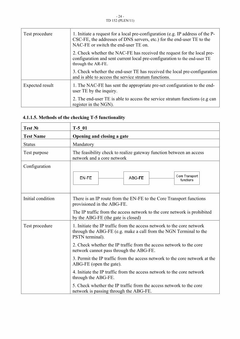
4.1.1.5. Methods of the checking T-5 functionality
Test № T-5_01
Test Name Opening and closing a gate
Status Mandatory
Test purpose The feasibility check to realize gateway function between an access network and a core network
Configuration
Initial condition There is an IP route from the EN-FE to the Core Transport functions provisioned in the ABG-FE.
The IP traffic from the access network to the core network is prohibited by the ABG-FE (the gate is closed)
Test procedure 1. Initiate the IP traffic from the access network to the core network through the ABG-FE (e.g. make a call from the NGN Terminal to the PSTN terminal).
2. Check whether the IP traffic from the access network to the core network cannot pass through the ABG-FE.
3. Permit the IP traffic from the access network to the core network at the ABG-FE (open the gate).
4. Initiate the IP traffic from the access network to the core network through the ABG-FE.
5. Check whether the IP traffic from the access network to the core network is passing through the ABG-FE.

- 25 - TD 152 (PLEN/11)
Expected result 1. The IP traffic from the access network to the core network cannot pass through the ABG-FE.
2. The IP traffic from the access network to the core network is passing through the ABG-FE since the gate is open.
Test № T-5_02
Test Name Packet filtering
Status Mandatory
Test purpose The feasibility check to filter the IP traffic at the ABG-FE according to the specific criteria.
Configuration
Initial condition There is an IP route from the EN-FE to the core network provisioned in the ABG-FE.
There is an IP traffic initiated from the EN-FE to the NGN through the ABG-FE.
There are no filters applied in the ABG-FE.
Test procedure 1. Check whether all IP traffic from the EN-FE to the NGN is passing through the ABG-FE.
2. Set a filter for the particular protocol of the IP traffic at the ABG-FE.
3. Check whether any packets of the selected protocol are transported via the common IP traffic from the ABG-FE to the core network.
4. Delete a filter from the ABG-FE.
5. Check whether all IP traffic from the EN-FE to the NGN is passing through the ABG-FE.
6. Repeat steps from 1 to 5 for filters based on the particular port and sender/receiver IP addresses.
Expected results 1. All IP traffic from the EN-FE to the NGN is passing through the ABG-FE.
2. There are no packets of the selected protocol/port/IP address in the common IP traffic.
3. All IP traffic from the EN-FE to the NGN is passing through the ABG-FE in normal way.
Test № T-5_03
Test Name Network address and port translation

- 26 - TD 152 (PLEN/11)
Status Mandatory
Test purpose The feasibility check to realize gateway function between an access network and a core network
Configuration
Initial condition There is an IP route from the EN-FE to the core network provisioned in the ABG-FE.
NAPT is enabled on the ABG-FE
IP address that will be used for replacing of initial IP source address (IP address of the EN-FE) is defined on the ABG-FE
Test procedure 1. Initiate a TCP/UDP session between the EN-FE and some node in NGN through the ABG-FE.
2. Measure IP source address, IP destination address, TCP/UDP source port, TCP/UDP destination port of packets which were transmitted from the EN-FE in context of TCP/UDP session from point 1
3. Measure IP source address, IP destination address, TCP/UDP source port, TCP/UDP destination port of packets which were transmitted from the ABG-FE to the NGN’s node in context of TCP/UDP session from point 1.
4. Check whether all checksums (IP header’s checksum, TCP/UDP checksum) in IP packets are correct.
5. Check whether IP destination addresses and TCP/UDP destination ports measured in points 2 and 3 are the same.
6. Check whether IP source address measured in point 3 complies with IP address from Initial Condition
7. Check whether the ABG-FE assigns new TCP/UDP source port (see point 3) and this port is the same for all packets transmitted in this direction in context of TCP/UDP session from point 1
8. Measure IP source address, IP destination address, TCP/UDP source port, TCP/UDP destination port of packets which were transmitted from the ABG-FE to the EN-FE in context of TCP/UDP session from point 1.
9. Check whether all checksums (IP header’s checksum, TCP/UDP checksum) in IP packets are correct.
10. Check whether IP source address and TCP/UDP source port measured in point 7 complies with IP destination address and TCP/UDP destination port measured in point 2.
11. Check whether IP destination address and TCP/UDP destination port measured in point 7 complies with IP source address and TCP/UDP source port measured in point 2.

- 27 - TD 152 (PLEN/11)
Expected result 1. Being transmitted through the ABG-FE IP packets contain correct IP addresses, TCP/UDP port numbers.
2. All checksums (IP header’s checksum, TCP/UDP checksum) in IP packets are correct.
Test № T-5_04
Test Name Media Relay for NAT traversal
Test purpose The feasibility check to realize gateway function between an access network and a core network
Configuration
Initial condition NAPT functions are enabled on ABG-FE
Test procedure 1. Initiate a call from SIP-terminal to legacy terminal connected through AMG-FE
2. Check whether information about media sessions that shall be established in context of the call from point 1 is provided to ABG-FE.
3. Check whether media sessions has been established successfully and end-users are able to receive and transmit voice data.
Expected result End-users are able to receive and transmit voice data through when NAPT functions are enabled.
Test № T-5_05
Test Name Collecting and reporting resource usage information
Status Mandatory
Test purpose The feasibility check to control resource usage at the border between an access network and a core network
Configuration
Initial condition There is an IP route from the EN-FE to the Core Transport functions provisioned in the ABG-FE.
The resource usage at the ABG-FE is under control of the PD-FE.

- 28 - TD 152 (PLEN/11)
Test procedure 1. Set network bandwidth usage restriction at the PD-FE to the certain value.
2. Initiate the IP traffic from the access network to the core network through the ABG-FE exceeding the maximum value of network bandwidth usage.
3. Check whether all IP packets exceeding the maximum value have been dropped by the ABG-FE.
4. Delete the restriction of the bandwidth usage from the ABG-FE.
5. Check whether the IP traffic from the access network to the core network is passing through the ABG-FE without any losses.
Expected result 1. The IP traffic is restricted at the ABG-FE according to the certain value of the network bandwidth usage.
2. All IP packets from the access network were successfully delivered to the core network through the ABG-FE without any losses.
Current functionality also requires testing of QoS parameters and mechanisms as buffer management, queuing and scheduling, traffic classification, marking, policing, shaping, and forwarding.
4.1.1.6. Methods of the checking T-6 functionality
Test № T-6_01
Test Name Packet filtering
Test purpose The feasibility check to support FireWall function between operator’s core network supporting the packet-based services
Configuration
Initial condition There is an IP route from the core network to the Other NGN provisioned in the IBG-FE.
There is an IP traffic initiated from the core network to the Other NGN through the IBG-FE.
There are no filters applied in the IBG-FE.

- 29 - TD 152 (PLEN/11)
Test procedure 1. Check whether all IP traffic from the core network to the Other NGN is passing through the IBG-FE.
2. Set a filter for the particular protocol of the IP traffic at the IBG-FE.
3. Check whether any packets of the selected protocol are transported via the common IP traffic from the IBG-FE to the Other NGN.
4. Delete a filter from the IBG-FE.
5. Check whether all IP traffic from the core network to the Other NGN is passing through the IBG-FE.
6. Repeat steps from 1 to 5 for filters based on the particular port and sender/receiver IP addresses.
Expected result 1. All IP traffic from the core network to the other NGN is passing through the IBG-FE.
2. There are no packets of the selected protocol/port/IP address in the common IP traffic.
3. All IP traffic from the core network to the other NGN is passing through the IBG-FE in the normal way.
Test № T-6_02
Test Name Network address and port translation
Status Mandatory
Test purpose The feasibility check to support FireWall function between operator’s core network supporting the packet-based services
Configuration
Initial condition There is an IP route from the core network to the other NGN provisioned in the IBG-FE.
NAPT is enabled on the IBG-FE
IP address that will be used for replacing initial IP source address (IP address of some node in the core network) is defined on the IBG-FE

- 30 - TD 152 (PLEN/11)
Test procedure 1. Initiate a TCP/UDP session between the core network and some node in the other NGN through the IBG-FE.
2. Measure IP source address, IP destination address, TCP/UDP source port, TCP/UDP destination port of packets which were transmitted from the core network in context of TCP/UDP session from point 1
3. Measure IP source address, IP destination address, TCP/UDP source port, TCP/UDP destination port of packets which were transmitted from the IBG-FE to the other NGN’s node in context of TCP/UDP session from point 1.
4. Check whether all checksums (IP header’s checksum, TCP/UDP checksum) in IP packets are correct.
5. Check whether IP destination addresses and TCP/UDP destination ports measured in points 2 and 3 are the same.
6. Check whether IP source address measured in point 3 complies with IP address from Initial Condition
7. Check whether the IBG-FE assigns new TCP/UDP source port (see point 3) and this port is the same for all packets transmitted in this direction in context of of TCP/UDP session from point 1
8. Measure IP source address, IP destination address, TCP/UDP source port, TCP/UDP destination port of packets which were transmitted from the IBG-FE to the core network in context of TCP/UDP session from point 1.
9. Check whether all checksums (IP header’s checksum, TCP/UDP checksum) in IP packets are correct.
10. Check whether IP source address and TCP/UDP source port measured in point 7 complies with IP destination address and TCP/UDP destination port measured in point 2.
11. Check whether IP destination address and TCP/UDP destination port measured in point 7 complies with IP source address and TCP/UDP source port measured in point 2.
Expected result 1. Being transmitted through the IBG-FE IP packets contain correct IP addresses, TCP/UDP port numbers.
2. All checksums (IP header’s checksum, TCP/UDP checksum) in IP packets are correct.
Current functionality also requires testing of QoS parameters and mechanisms such as buffer management, queuing and scheduling, traffic classification, marking, policing, shaping, and forwarding.
4.1.1.7. Methods of the checking T-7 functionality
Test № T-7_01
Test Name Interworking media trunks circuit-switched network with packet-based transport

- 31 - TD 152 (PLEN/11)
Status Mandatory
Test purpose The feasibility check to provide interworking between the packet-based transport used in the NGN and trunks from the circuit-switched network
Configuration
Initial condition There is a media session established between the circuit-switched network and the TMG-FE.
Test procedure Check whether the circuit-switched network could receive and transmit any media information from/to the NGN through TMG-FE simultaneously in the real-time mode.
Expected results The Circuit-switched network receives and transmits media information simultaneously in the real-time mode from/to the NGN through the TMG-FE.
Test № T-7_02
Test Name Codecs for trunk interworking
Status Mandatory
Test purpose The feasibility check to support payload processing in part of different codecs for trunk interworking
Configuration
Initial condition There is a connection between the circuit-switched network and the TMG-FE. G.711 (a-law) codec is chosen for payload processing on the TMG-FE.
Test procedure 1. Initiate a call from the circuit-switched network to the TMG-FE.
2. Check whether all media information from the circuit-switched network passing through the TMG-FE is encoded via G.711 (a-law) codec.
3. Release a call from the circuit-switched network side.
4. Repeat steps from 1 to 3 for G.723, G.729 and other codecs types .
Expected results Media information from the circuit-switched network is encoded via selected codec.
Test № T-7_03
Test Name Echo cancellers

- 32 - TD 152 (PLEN/11)
Status Mandatory
Test purpose The feasibility check to support payload processing in part of echo cancellers for trunk interworking
Configuration
Initial condition There is a connection between the circuit-switched network and the TMG-FE. The echo cancellation function on the TMG-FE is switched off.
Test procedure 1. Initiate a call from the circuit-switched network to the TMG-FE.
2. Check the quality of the speech for a call.
3. Release a call from the circuit-switched network side.
4. Switch on the echo cancellation function on the TMG-FE.
5. Initiate a call from the circuit-switched network to the TMG-FE.
6. Check the quality of the speech for a call.
Expected results 1. There is an echo occuring during the first call.
2. There is no echo for the second call.
4.1.1.8. Methods of the checking T-8 functionality
Test № T-8_01
Test Name Allocation of specialized media resources
Status Mandatory
Test purpose The feasibility check to provide payload processing in part of specialized media resources allocation
Configuration
Initial condition There are no specialized media resources allocated at the MRP-FE.

- 33 - TD 152 (PLEN/11)
Test procedure 1. Initiate a request from the end-user terminal connected to the NGN through the access network or PSTN for specialized media resource (e.g. special tone), which has the certain ID at the MRP-FE.
2. Check whether the MRC-FE has allocated specialized media resource at the MRP-FE with the appropriate ID.
3. Check whether the end-user terminal can receive requested specialized media resource.
4. Check whether after completion of specialized media resource the media session is released.
Expected result 1. The MRC-FE has sent the request to the MRP-FE to allocate specialized media resource with the appropriate ID.
2. The end-user terminal is receiving requested specialized media resource.
3. The MRC-FE has sent the request to the MRP-FE to dislocate specialized media resource with an appropriate ID. The media session is released.
Test № T-8_02
Test Name Collection and generation of DTMF signals
Status Mandatory
Test purpose The feasibility check to provide payload processing in part of DTMF signals collection and generation
Configuration
Initial condition There are several legacy terminals connected to the NGN through the AMG-FE or PSTN.

- 34 - TD 152 (PLEN/11)
Test procedure 1. Initiate a DTMF signals sequence (e.g. digits of the number) from the legacy terminal to the NGN.
2. Check whether the MRP-FE has received a DTMF signals sequence and has sent it to the MRC-FE accordingly.
3. Initiate a DTMF signals sequence from the MRC-FE to the legacy terminal through the MRP-FE (e.g. Calling Line Identification functionality for the legacy terminal).
4. Check whether the MRP-FE has received the DTMF signals sequence and has sent it to the legacy terminal accordingly.
5. Check whether the legacy terminal has received the DTMF signals sequence.
Expected result 1. The MRP-FE has received the DTMF signals sequence and has sent it to the MRC-FE accordingly.
2. The MRP-FE has received the DTMF signals sequence and has sent it to the legacy terminal accordingly.
3. The legacy terminal has received the DTMF signals sequence.
Test № T-8_03
Test Name Generation of tone signals.
Status Mandatory
Test purpose The feasibility check provide payload processing in part of tones generation
Configuration
Initial condition There are several end-user terminals connected to the NGN through the access network or PSTN.
Test procedure 1. Initiate a request from the end-user terminal for a special tone (e.g. special melody), which has the certain ID at the MRP-FE.
2. Check whether the MRC-FE has allocated the special tone at the MRP-FE with the appropriate ID.
3. Check whether the end-user terminal can receive the appropriate tone.
4. Check whether after completion of the tone the media session is released and the resource is dislocated from the MRP-FE.

- 35 - TD 152 (PLEN/11)
Expected result 1. The MRC-FE has sent the request to the MRP-FE to allocate the special tone for the current media session with the appropriate ID.
2. The end-user terminal is receiving requested special tone.
3. The MRC-FE has sent the request to the MRP-FE to dislocate the special tone with the appropriate ID. The media session is released.
Test № T-8_04
Test Name Generation of announcements.
Status Mandatory
Test purpose The feasibility check provide payload processing in part of announcement generation
Configuration
Initial condition There are several end-user terminals connected to the NGN through the access network or PSTN.
Test procedure 1. Initiate a request from the end-user terminal for a special announcement (e.g. “Thank you for your call”), which has the certain ID at the MRP-FE.
2. Check whether the MRC-FE has allocated the special announcement at the MRP-FE with the appropriate ID.
3. Check whether the end-user terminal can receive the appropriate announcement.
4. Check whether after completion of the announcement the media session is released and the resource is dislocated from the MRP-FE.
Expected result 1. The MRC-FE has sent the request to the MRP-FE to allocate the special announcement for the current media session with the appropriate ID.
2. The end-user terminal is receiving requested announcement.
3. The MRC-FE has sent the request to the MRP-FE to dislocate the special announcement with an appropriate ID. The media session is released.
4.1.1.9. Methods of the checking T-9 functionality
Test № T-9_01

- 36 - TD 152 (PLEN/11)
Test Name Signaling interworking with PSTN/ISDN/IN (2CAS, SS7)
Status Mandatory
Test purpose The feasibility check to provide signaling transport interworking between the NGN and existing networks
Configuration
Initial condition There is a signaling connection between the PSTN/ISDN/IN and the SG-FE.
Test procedure 1. Initiate a call from PSTN/ISDN/IN to the NGN.
2. Check whether the SG-FE can backhaul PSTN/ISDN/IN call control signaling to the MGC-FE for processing using the appropriate signaling protocol.
3. Check whether a call has been established between PSTN/ISDN/IN and the NGN.
4. Release a call from the PSTN/ISDN/IN side.
5. Check whether a call has been terminated.
Expected results 1. SG-FE backhauls PSTN/ISDN/IN call control signaling to the MGC-FE using the appropriate signaling protocol.
2. A call is established between PSTN/ISDN/IN and the NGN.
3. A call is terminated.
4.1.1.10. Methods of the checking T-10 functionality
Test № T-10_01
Test Name IP address allocation to terminals
Status Mandatory
Test purpose The feasibility check to provide an access to the network for the terminal
Configuration
Initial condition NAC-FE’s database contains information about IP addresses compliance with certain terminals’ identifiers

- 37 - TD 152 (PLEN/11)
Test procedure 1. From terminal, transmit request for IP address allocation
2. Check whether this request contains terminal’s identification information
3. Check whether NAC-FE has transmitted information about IP address allocation in answer to request from point 1
4. Check whether this answer contains IP address that complies with NAC-FE’s database (see Initial condition), i.e. IP address has been allocated in compliance with terminal’s identification information
Expected result IP address has been allocated to terminal in compliance with terminal’s identification information
4.1.1.11. Methods of the checking T-11 functionality
Test № T-11_01
Test Name Users or terminals identification in networks
Status Mandatory
Test purpose The feasibility check to provide authentication and authorization in the transport stratum
Configuration
Initial condition TUP-FE’s database contains user profiles with data required for authentication and authorization.
EU-FE is configured according to one of the user profiles from TUP-FE’s database

- 38 - TD 152 (PLEN/11)
Test procedure 1. From EU-FE, initiate any procedure that requires authentication and authorization in the transport stratum (e.g. initiate ppp session establishment from an end-user terminal).
2. Check whether TAA-FE has received authentication and authorization request, and appropriate information is provided correctly (e.g. correct username and password, IP address and MAC address etc).
3. Check whether TAA-FE has retrieved necessary authentication and authorization data from TUP-FE.
4. Check whether TAA-FE has transmitted message about successful authentication and authorization to the functional entity that has sent authentication and authorization request.
5. Configure incorrect identification information on EU-FE (e.g. wrong username and password, IP address and MAC address etc)
6. Initiate any procedure that requires authentication and authorization in the transport stratum (e.g. initiate ppp session establishment from an end-user terminal).
7. Check whether TAA-FE has received authentication and authorization request, and appropriate information is provided according to point 6.
8. Check whether TAA-FE has retrieved necessary authentication and authorization data from TUP-FE.
9. Check whether TAA-FE has transmitted message about unsuccessful authentication and authorization to the entity that has sent authentication and authorization request.
Expected result TAA-FE is able to provide authentication and authorization in the transport stratum
4.1.1.12. Methods of the checking T-12 functionality
Test № T-12_01
Test Name User profiles, subscriber-related location data, and presence status data
Status Mandatory
Test purpose The feasibility check to store, update and provide user data
Configuration
Initial condition TUP-FE’s database contains at least one user profile (user profile 1) with some data.

- 39 - TD 152 (PLEN/11)
Test procedure 1. Initiate a query of the user profile 1’s data.
2. Check whether TUP-FE has provided appropriate information.
3. Initiate an updating of some information in the user profile 1 (e.g. P-CSC-FE address).
4. Initiate a query of the user profile 1’s data.
5. Check whether TUP-FE has provided the updated user profile 1’s data (e.g. new P-CSC-FE address).
Expected result 1. User profile 1 is stored in the TUP-FE’s database.
2. Data from the user profile 1 was updated in accordance with information from point 3 of test procedure.
Test № T-12_02
Test Name Responses to queries for user profiles
Status Mandatory
Test purpose The feasibility check to provides access to user data
Configuration
Initial condition TUP-FE’s database contains at least one user profile (user profile 1) with some data.
Test procedure 1. Initiate a query of the user profile 1’s data from some entity that have rights to access to this information.
2. Check whether TUP-FE has provided appropriate information.
3. Initiate a query of the user profile 1’s data from some entity that have no rights to access to this information.
4. Check whether TUP-FE has rejected appropriate request.
Expected result TUP-FE provides filtered access to the user data
4.1.1.13. Methods of the checking T-13 functionality
Methods of testing for this functionality will be considered in the context of the other recommendations according to development of NGN roaming and mobility functionality specifications.
4.1.1.14. Methods of the checking T-14 functionality
Test № T-14_01

- 40 - TD 152 (PLEN/11)
Test Name Forwarding network configuration parameters and authentication and authorization requests
Status Mandatory
Test purpose The feasibility check to forward requests for network configuration parameters and authentication and authorization requests
Configuration
Initial condition There is a EU-FE that is able to request network configuration parameters
Test procedure 1. From EU-FE, initiate any procedure that requests network configuration parameters and requires authentication and authorization in the transport stratum.
2. Check whether requests for network configuration parameters was forwarded to NAC-FE by AM-FE.
3. Check whether authentication and authorization request was sent to the TAA-FE by AM-FE.
4. Check whether network configuration parameters was forwarded to the EU-FE (authentication and authorization procedure shall be successful).
Expected result 1. AM-FE forwards the requests for network configuration parameters to/from the NAC-FE.
2. AM-FE forwards the requests to the TAA-FE to authenticate and authorize the user.
4.1.1.15. Methods of the checking T-15 functionality
Methods of testing for this functionality will be considered in the context of the other recommendations according to development of the new NGN specifications.
4.1.1.16. Methods of the checking T-16 functionality
Methods of testing for this functionality will be considered in the context of the other recommendations according to development of the new NGN specifications.
4.1.1.17. Methods of the checking T-17 functionality
Methods of testing for this functionality will be considered in the context of the other recommendations according to development of the new NGN specifications.
4.1.1.18. Methods of the checking S-1 functionality

- 41 - TD 152 (PLEN/11)
Test № S-1_01
Test Name Interaction with AS
Status Mandatory
Test purpose The feasibility check to interact with the Application/Service Support functions to trigger requested services
Configuration
Initial condition There is a set of specific services (e.g. IN services) implemented at the AS-FE. The S-CSC-FE is configured to detect and forward all specific services requests to the AS-FE.
Test procedure 1. Initiate a request for a service provided by the AS-FE from the EU-FE or PSTN subscriber.
2. Check whether a request for a specific service has been detected by the S-CSC-FE and forwarded to the AS-FE.
3. Check whether the AS-FE has sent an appropriate response to the S-CSC-FE with instructions on handling the request.
Expected result 1. The request for a specific service has been received by the S-CSC-FE and forwarded to the AS-FE.
2. The AS-FE has sent an appropriate response to the correct S-CSC-FE containing instructions for handling a specific service request.
Test № S-1_02
Test Name Registration
Status Mandatory
Test purpose The feasibility check to process requests from users (and terminals) for registration
Configuration
Initial condition There is a SIP-terminal connected to the NGN. It is configured to send all SIP messages through the P-CSC-FE.

- 42 - TD 152 (PLEN/11)
Test procedure 1. Initiate a REGISTER request from the SIP-terminal.
2. Check whether a REGISTER request has been received by the I-CSC-FE from the P-CSC-FE and forwarded to the S-CSC-FE.
3. Check whether after receiving the REGISTER request from the I-CSC-FE the S-CSC-FE has sent a 401 (Unauthorized) response in order to authenticate the end-user.
4. Check whether after receiving the second REGISTER request with authorization data from the I-CSC-FE the S-CSC-FE has updated specific information about the end-user in the SUP-FE (e.g. it’s status).
Expected result 1. The S-CSC-FE has received the REGISTER request from a SIP-terminal through the I-CSC-FE.
2. The S-CSC-FE has sent a 401 (Unauthorized) response with authorization data in the field WWW-Authenticate.
3. The S-CSC-FE has updated specific information about the end-user in the SUP-FE.
4. The S-CSC-FE has sent a successful registration response to the SIP terminal in reverse way.
Test № S-1_03
Test Name Routing messages
Status Mandatory
Test purpose The feasibility check to route messages to terminals based on the routing (location) information obtained at registration
Configuration
Initial condition There are two SIP terminals (SIP-1, SIP-2) connected to the NGN and registered on the same S-CSC-FE. One of them uses the P-CSC-FE №1 and another SIP terminal uses the P-CSC-FE №2 accordingly.
- 43 - TD 152 (PLEN/11)
Test procedure 1. Initiate a call from PSTN to the SIP-1 terminal.
2. Check whether the S-CSC-FE has received an INVITE message with the Request URI field equal to the SIP-1 URI.
3. Check whether the S-CSC-FE has forwarded the INVITE message to the P-CSC-FE №1 based on the routing (location) information obtained at registration.
4. Release the call from PSTN side.
5. Initiate a call from PSTN to the SIP-2 terminal.
6. Check whether the S-CSC-FE has received an INVITE message with the Request URI field equal to the SIP-2 URI and forwarded the INVITE message to the P-CSC-FE №2.
Expected result 1. The S-CSC-FE has received an INVITE message with the Request URI field equal to the SIP-1 URI.
2. The S-CSC-FE has forwarded the INVITE message to the P-CSC-FE №1.
3. The S-CSC-FE has forwarded the second INVITE message to the P-CSC-FE №2.
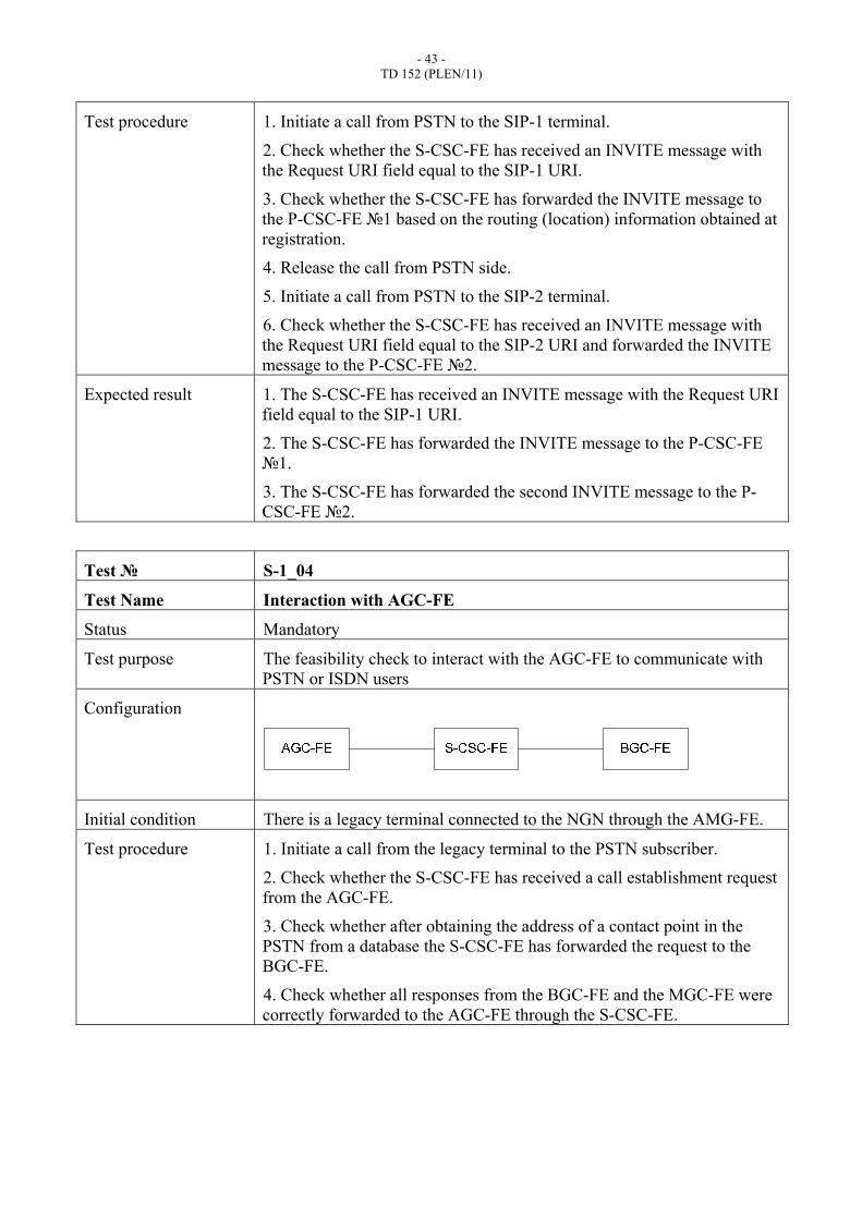
Test № S-1_04
Test Name Interaction with AGC-FE
Status Mandatory
Test purpose The feasibility check to interact with the AGC-FE to communicate with PSTN or ISDN users
Configuration
Initial condition There is a legacy terminal connected to the NGN through the AMG-FE.
Test procedure 1. Initiate a call from the legacy terminal to the PSTN subscriber.
2. Check whether the S-CSC-FE has received a call establishment request from the AGC-FE.
3. Check whether after obtaining the address of a contact point in the PSTN from a database the S-CSC-FE has forwarded the request to the BGC-FE.
4. Check whether all responses from the BGC-FE and the MGC-FE were correctly forwarded to the AGC-FE through the S-CSC-FE.

- 44 - TD 152 (PLEN/11)
Expected result 1. The S-CSC-FE has received a call establishment request from the AGC-FE.
2. The S-CSC-FE has forwarded the request to the BGC-FE responsible for the requested PSTN breakout.
3. All provisional and final responses from the BGC-FE and the MGC-FE were correctly forwarded to the AGC-FE through the S-CSC-FE.
Test № S-1_05
Test Name Support of services
Status Mandatory
Test purpose The feasibility check to maintain a session state as needed by the network operator for support of services
Configuration
Initial condition There is a specific service (e.g. Voicemail) implemented at the AS-FE. The S-CSC-FE is configured to detect and process all specific service requests under the AS-FE control.
Test procedure 1. Initiate a request for a service provided by the AS-FE (e.g. Voicemail) from the EU-FE or PSTN subscriber.
2. Check whether a request for a specific service has been detected by the S-CSC-FE and forwarded to the AS-FE.
3. Check whether the AS-FE has sent a command to the S-CSC-FE to change the current session state.
4. Check whether the S-CSC-FE has changed the current session state (e.g. has connected the end-user to the media resources) and the end-user has received the requested service (e.g. left a message in the voicemail box).
Expected result 1. The request for a specific service has been received by the S-CSC-FE and forwarded to the AS-FE.
2. The AS-FE has sent a command to the S-CSC-FE to change the current session state.
3. The S-CSC-FE has changed the current session state and the end-user has received the requested service.
4.1.1.19. Methods of the checking S-2 functionality
Test № S-2_01
Test Name Forward a register request from terminal

- 45 - TD 152 (PLEN/11)
Status Mandatory
Test purpose The feasibility check to forward a register request received from a terminal to an I-CSC-FE determined using the home domain name, as provided by the terminal
Configuration
Initial condition There is a SIP-terminal connected to the NGN. It is configured to send all SIP messages through the P-CSC-FE. SIP URI of the terminal is assigned to a specific domain (e.g. zniis.ru). This specific domain is associated with one of the I-CSC-FE.
Test procedure 1. Initiate a REGISTER request from the SIP-terminal.
2. Check whether a REGISTER request has been received by the P-CSC-FE.
3. Check whether the P-CSC-FE on receipt of a REGISTER request forwards the message to the correct I-CSC-FE according to the home domain name in the SIP URI.
Expected result 1. The P-CSC-FE has received a REGISTER request from a SIP-terminal.
2. The P-CSC-FE has forwarded a REGISTER request to the I-CSC-FE associated with the domain name in the SIP URI and has received the name of the SIP server (e.g., S-CSC-FE) in a response from the I-CSC-FE.
Test № S-2_02
Test Name Forward SIP messages from the terminal to the SIP server
Status Mandatory
Test purpose The feasibility check to forward SIP messages received from the terminal to the SIP server (e.g., an S-CSC-FE) whose name the P-CSC-FE has received as a result of the registration procedure
Configuration
Initial condition There is a SIP-terminal connected to the NGN. It is registered on the P/S/I-CSC-FE. There is a specific S-CSC-FE assigned to a SIP-terminal on the P-CSC-FE.

- 46 - TD 152 (PLEN/11)
Test procedure 1. Initiate an INVITE request from the SIP-terminal.
2. Check whether an INVITE request has been received by the P-CSC-FE.
3. Check whether the P-CSC-FE on receipt of an INVITE request forwards the message to the correct S-CSC-FE according to the information on it’s database.
Expected result 1. The P-CSC-FE has received an INVITE request from a SIP-terminal.
2. The P-CSC-FE has forwarded an INVITE request to the S-CSC-FE assigned to the specific SIP-terminal.
Test № S-2_03
Test Name Forward a SIP request to the SIP-terminal
Status Mandatory
Test purpose The feasibility check to forward SIP requests or responses to the SIP-terminal
Configuration
Initial condition There is a SIP-terminal connected to the NGN. It is registered on the P/S/I-CSC-FE. There is a specific S-CSC-FE assigned to the SIP-terminal on the P-CSC-FE. Also there is a legacy terminal connected to the NGN.
Test procedure 1. Initiate a call from the legacy terminal to the SIP-terminal.
2. Check whether an INVITE request has been received by the P-CSC-FE from the S-CSC-FE.
3. Check whether the P-CSC-FE on receipt of an INVITE request forwards the message to the correct SIP-terminal.
4. Check whether the P-CSC-FE on receipt of a response from the SIP-terminal forwards the message to the S-CSC-FE.
Expected result 1. The P-CSC-FE has received an INVITE request from the S-CSC-FE.
2. The P-CSC-FE has forwarded an INVITE request to the correct SIP-terminal determined in the SIP URI.
3. The P-CSC-FE has forwarded back the response from the SIP-terminal to the same S-CSC-FE.
Test № S-2_04
Test Name Emergency session establishment requests
Status Mandatory

- 47 - TD 152 (PLEN/11)
Test purpose The feasibility check to detect and handle emergency session establishment requests
Configuration
Initial condition There is a SIP-terminal connected to the NGN. It is registered on the P/S/I-CSC-FE. There is a specific S-CSC-FE assigned to the SIP-terminal on the P-CSC-FE.
The end-user is not allowed to make calls from this SIP-terminal (e.g. user account is blocked because of lack of money resources).
The P-CSC-FE is configured to send all emergency call establishment requests to the S-CSC-FE.
Test procedure 1. Initiate a call from the SIP-terminal to the NGN.
2. Check whether the P-CSC-FE has not forwarded a call establishment request from the SIP-terminal to the S-CSC-FE.
3. Initiate an emergency call from the SIP-terminal (e.g. 112, 911, etc.).
4. Check whether the P-CSC-FE has detected an emergency call and has forwarded an INVITE request to the correct S-CSC-FE.
Expected result 1. A normal call could not be established.
2. An emergency call could be processed.
Test № S-2_05
Test Name Security
Status Optional
Test purpose The feasibility check to maintain a security association between itself and each terminal
Configuration
Initial condition There is an end-user connected to the NGN via SIP-terminal. It is not registered in the NGN. SIP-terminal and the P-CSC-FE are configured to establish a Security Associations (SAs) for each session.

- 48 - TD 152 (PLEN/11)
Test procedure 1. Initiate a registration from the end-user.
2. Check whether the SIP-terminal has transmitted all security parameters required for SA establishment on the SIP-terminal side to the P-CSC-FE.
3. Check whether the P-CSC-FE has sent the 401 (Unauthorized) response with security parameters required for SA establishment on the P-CSC-FE side.
4. Check whether the SA has been established between the SIP-terminal and the P-CSC-FE and the SIP messages exchange is provided in secure mode.
Expected result The SA between the SIP-terminal and the P-CSC-FE has been successfully established.
Test № S-2_06
Test Name NAT traversal
Status Mandatory
Test purpose The feasibility check to support an NAPT Proxy Function (NPF) for network address hiding and remote NAT traversal
Configuration
Initial condition There are two SIP-terminals connected to the NGN. They are registered on the P-CSC-FE and the I-CSC-FE. There is a specific S-CSC-FE assigned to these SIP-terminals on the P-CSC-FE.
Test procedure 1. Initiate a call from the SIP-terminal to another one.
2. Check whether the address binding information was provided by RACF.
3. Check whether the P-CSC-FE modifies the addresses and/or ports contained in the message bodies of SIP signaling messages, according to the information provided by the RACF.
Expected result 1. The address binding information is correct.
2. Signaling messages processed by P-CSC-FE contain correct address information.
4.1.1.20. Methods of the checking S-3 functionality

- 49 - TD 152 (PLEN/11)
Test № S-3_01
Test Name Registration
Status Mandatory
Test purpose The feasibility check to assign an S-CSC-FE to a user performing SIP registration
Configuration
Initial condition There is a SIP-terminal connected to the NGN. It is configured to send all SIP messages through the P-CSC-FE.
Test procedure 1. Initiate a REGISTER request from the SIP-terminal.
2. Check whether a REGISTER request has been forwarded by the P-CSC-FE to the I-CSC-FE.
3. Check whether the I-CSC-FE has assigned the S-CSC-FE to a user performing SIP registration and has sent the corresponding name of the S-CSC-FE to the P-CSC-FE.
Expected result 1. The I-CSC-FE has received a REGISTER request from a SIP-terminal through the P-CSC-FE.
2. The I-CSC-FE has stored the address of the S-CSC-FE assigned to the user in the SUP-FE.
3. The P-CSC-FE has received the name of the S-CSC-FE in a response from the I-CSC-FE.
Test № S-3_02
Test Name Session-related and session-unrelated flows
Status Mandatory
Test purpose The feasibility check to obtain from the SUP-FE the address of the currently assigned S-CSC-FE.
The feasibility check to forward a SIP request or response to the S-CSC-FE determined by the above step for incoming sessions
Configuration

- 50 - TD 152 (PLEN/11)
Initial condition There is a SIP-terminal connected to the NGN. There is a specific S-CSC-FE assigned to the SIP-terminal.
Test procedure 1. Initiate a call from the PSTN subscriber to the SIP-terminal.
2. Check whether the I-CSC-FE has received a call establishment request from the MGC-FE.
3. Check whether the I-CSC-FE has retrieved the address of the S-CSC-FE assigned to the SIP-terminal.
4. Check whether after receiving the S-CSC-FE address from the SUP-FE the I-CSC-FE has forwarded a call establishment request to the corresponding S-CSC-FE.
Expected result 1. The I-CSC-FE has received a call establishment request from the MGC-FE.
2. The I-CSC-FE has received the correct S-CSC-FE address from the SUP-FE.
3. The I-CSC-FE has forwarded a call establishment request to the appropriate S-CSC-FE.
4.1.1.21. Methods of the checking S-4 functionality
Test № S-4_01
Test Name Obtaining of the address
Status Mandatory
Test purpose The feasibility check to find the address of the physical entity that holds the subscriber data for a given user identity when multiple
Configuration
Initial condition There are minimum two Physical Entities of SUP-FE (SUP-PE-1 and SUP-PE-2) in the NGN. The subscriber data for a user’s identifier №1 are stored in the SUP-PE-1 and for the user’s identifier №2 – in the SUP-PE-2. The SL-FE contains the addresses of all SUP-PEs.

- 51 - TD 152 (PLEN/11)
Test procedure 1. Initiate a registration for an end-user with identifier №1.
2. Check whether the S-CSC-FE in order to find out the SUP-FE which holds subscriber data for the end-user with identifier №1 has sent the request to the SL-FE.
3. Check whether the SL-FE has received the request from the S-CSC-FE and returned the response with the address of the SUP-PE-1.
4. Initiate a registration for an end-user with identifier №2.
5. Repeat actions from 1 to 2 for the end-user with identifier №2.
6. Check whether the SL-FE has received the request with user’s identifier №2 from the S-CSC-FE and returned the response with the address of the SUP-PE-2.
Expected result 1. The S-CSC-FE has sent the request to the SL-FE with user’s identifier №1.
2. The SL-FE has returned the response with the address of the SUP-PE-1.
3. For the second request from the S-CSC-FE with user’s identifier №2 the SL-FE has returned the response with the address of the SUP-PE-2.
4.1.1.22. Methods of the checking S-5 functionality
Test № S-5_01
Test Name User profile management
Status Mandatory
Test purpose The feasibility check to perform basic data management and maintenance functions
Configuration
Initial condition There is an end-user terminal connected to the NGN. There is no user profile for this end-user in the SUP-FE.

- 52 - TD 152 (PLEN/11)
Test procedure 1. Create an user profile for the end-user with unique identifier and a basic set of services.
2. Check whether the user profile has been successfully stored in the SUP-FE.
3. Check whether the end-user status is ‘not registered’.
4. Initiate a registration for the end-user.
5. Check whether the SUP-FE has updated the status of end-user in the user profile by inquiry from the S-CSC-FE.
6. Delete the user profile from the SUP-FE.
7. Check whether the user profile has been deleted from the SUP-FE.
Expected result 1. New user profile has been successfully stored in the SUP-FE.
2. The end-user status is ‘not registered’.
3. The SUP-FE has updated the status of the end-user after registration.
4. The user profile has been deleted from the SUP-FE.
Test № S-5_02
Test Name Providing access to user data
Status Mandatory
Test purpose The feasibility check to response to queries for user profiles
Configuration
Initial condition There is an user profile for the specific end-user in the SUP-FE. Specific S-CSC-FE is assigned for serving the end-user in the user profile. The end-user is not registered at the SUP-FE.
Test procedure 1. Initiate a registration for the specific end-user.
2. Check whether after receiving of the S-CSC-FE name request from the I-CSC-FE the SUP-FE has returned correct S-CSC-FE name.
3. Check whether after receiving of the user profile request from the S-CSC-FE the SUP-FE has responded with a user profile of the appropriate end-user.
Expected result 1. The SUP-FE has sent the correct name of S-CSC-FE assigned to the end-user to the I-CSC-FE.
2. The SUP-FE has sent the user profile of the requested end-user to the S-CSC-FE.

- 53 - TD 152 (PLEN/11)
4.1.1.23. Methods of the checking S-6 functionality
Test № S-6_01
Test Name Rights of end-user
Status Mandatory
Test purpose The feasibility check to ensure that the end-user has valid utilization rights for the requested service
Configuration
Initial condition There is an end-user connected to the NGN. The end-user is registered in the NGN.
The end-user has the rights for a basic set of services, but has no rights for a specific service (e.g.Voicemail).
Test procedure 1. Initiate a request for the basic service from the end-user.
2. Check whether the S-CSC-FE has received the request for a service from the end-user and has transmitted the request for authorization to the SAA-FE.
3. Check whether the SAA-FE in order to ensure that the end-user has valid utilization rights for the requested service has send the user profile request to the SUP-FE.
4. Check whether the SUP-FE has returned the user profile to the SAA-FE.
5. Check whether the SAA-FE after receiving of the user profile has made a decision to authorize the service request and has sent successful authorization response to the end-user through the S-CSC-FE.
6. Repeat the actions from 1 to 4 for a specific service.
7. Check whether the SAA-FE has sent unsuccessful authorization response to the end-user through the S-CSC-FE.
Expected result 1. The SAA-FE has authorized the end-user request for a basic service.
2. The SAA-FE has not authorized the end-user request for the specific service.
Test № S-6_02
Test Name Using policy rules
Test purpose The feasibility check to provide a policy control at the service level by using policy rules contained in a user profile database

- 54 - TD 152 (PLEN/11)
Configuration
Initial condition There is an end-user connected to the NGN. The end-user is registered in the NGN.
The end-user has the rights for a basic set of services, but with a certain policy (e.g. international calls are denied).
Test procedure 1. Initiate a request for the basic service which meet the requirement of the policy rules from the end-user.
2. Check whether the S-CSC-FE has received the request for a service from the end-user and has transmitted the request for authorization to the SAA-FE.
3. Check whether the SAA-FE in order to ensure that the end-user has rights for the requested service has send the user profile request to the SUP-FE.
4. Check whether the SUP-FE has returned the user profile to the SAA-FE.
5. Check whether the SAA-FE after receiving of the user profile has made a decision to authorize the service request and has sent successful authorization response to the end-user through the S-CSC-FE.
6. Repeat the actions from 1 to 4 for a basic service which does not meet the requirements of the policy rules.
7. Check whether the SAA-FE has sent unsuccessful authorization response to the end-user through the S-CSC-FE.
Expected result 1. The SAA-FE has authorized the end-user request for a basic service which meet the requirement of the policy rules.
2. The SAA-FE has not authorized the end-user request for the basic service which does not meet the requirements of the policy rules.
Test № S-6_03
Test Name Mobility management
Test purpose The feasibility check to provide access to NGN services in a visited network
Configuration
Initial condition There is an end-user connected to the visited NGN via SIP-terminal. The roaming function is activated for the end-user.

- 55 - TD 152 (PLEN/11)
Test procedure 1. Initiate a request for the basic service from the end-user located in the visited network.
2. Check whether the S-CSC-FE in the home network has received the request for a service from the P-CSC-FE of the visited network and has transmitted the request for authorization to the SAA-FE.
3. Check whether the SAA-FE in order to ensure that the end-user has valid rights for the requested service in the visited network has sent the user profile request to the SUP-FE.
4. Check whether the SUP-FE has returned the user profile to the SAA-FE.
5. Check whether the SAA-FE after receiving of the user profile has made a decision to authorize the service request and has sent successful authorization response to the end-user through the S-CSC-FE.
6. Deactivate the roaming function
7. Repeat the actions from 1 to 4.
8. Check whether the SAA-FE has sent unsuccessful authorization response to the end-user through the S-CSC-FE.
Expected result 1. The SAA-FE has authorized the end-user request for the service in the visited network.
2. After deactivation of the roaming function for the end-user the SAA-FE has not authorized the end-user request for the service in the visited network.
4.1.1.24. Methods of the checking S-7 functionality
Methods of testing for this functionality will be considered in the context of the other recommendations according to development of the new NGN specifications.
4.1.1.25. Methods of the checking S-8 functionality
Test № S-8_01
Test Name Signaling translation and conversion
Status Mandatory
Test purpose The feasibility check to provide signaling translation and conversion between up-links and down-links or between SIP and H.248-based control
Configuration
Initial condition There is a legacy end-user terminal connected to the AMG-FE

- 56 - TD 152 (PLEN/11)
Test procedure 1. Initiate a call from a legacy end-user terminal to the NGN.
2. Check whether a call has reached the S-CSC-FE through the up-link from the AGC-FE.
3. Check whether called party number, calling party number, session description parameters were successfully translated from the down-link into the up-link signaling protocols and in reverse way
Expected results The most call sensitive parameters were correctly translated from the down-link into the up-link signaling protocols and in reverse way
Test № S-8_02
Test Name Providing ISDN supplementary services
Status Mandatory
Test purpose The feasibility check to initiate and terminate UNI protocols in order to provide ISDN supplementary services
Configuration
Initial condition There is a connection between the ISDN EU-FE and the AMG-FE.
Test procedure 1. Initiate a request for a supplementary service from ISDN EU-FE to the AMG-FE using the UNI protocol.
2. Check whether the AMG-FE backhauls initial UNI protocol signaling to the AGC-FE using the appropriate signaling protocol.
3. Check whether a supplementary service request has been received by the AGC-FE and forwarded to the S-CSC-FE for processing.
4. Check whether the appropriate responses have been sent from the S-CSC-FE to the EU-FE through the AMG-FE and the AGC-FE.
5. Check the realization of the supplementary service logic for the ISDN EU-FE.
Expected results 1. The AMG-FE backhauls UNI protocol signaling to the AGC-FE using the appropriate signaling protocol.
2. The S-CSC-FE has sent responses specific to the supplementary service logic through the AGC-FE.
3. The ISDN EU-FE has received the requested supplementary service.
Test № S-8_03
Test Name Forwarding requests
Status Mandatory

- 57 - TD 152 (PLEN/11)
Test purpose The feasibility check to process and forward requests and session control flow from the AMG-FE to the S-CSC-FE
Configuration
Initial condition There is a connection between the EU-FE and the AMG-FE.
Test procedure 1. Initiate a call from the EU-FE to the NGN through the AMG-FE.
2. Check whether a call control signaling received from the AMG-FE processed and forwarded by the AGC-FE to the S-CSC-FE.
3. Check whether after receiving a call establishment request the S-CSC-FE sends the appropriate response in reverse way through the AGC-FE to the affected AMG-FE.
4. Check whether a call has been established between EU-FE and the NGN through the AMG-FE.
5. Release a call from the EU-FE side.
6. Check whether after receiving a call termination request the S-CSC-FE sends the acknowledge response in reverse way through the AGC-FE to the affected AMG-FE.
7. Check whether a call has been terminated.
Expected results 1. A request for a call establishment received from the AMG-FE, processed and forwarded by the AGC-FE to the S-CSC-FE.
2. The S-CSC-FE has sent the appropriate response in reverse way through the AGC-FE to the affected AMG-FE.
3. A call is established between the EU-FE and the NGN through the AMG-FE.
4. The S-CSC-FE has sent the acknowledge response in reverse way through the AGC-FE to the affected AMG-FE.
5. A call is terminated.
Test № S-8_04
Test Name Forwarding value-added service requests
Status Mandatory
Test purpose The feasibility check to process and forward value-added service requests from the AMG-FE to the AS-FE through the S-CSC-FE
Configuration

- 58 - TD 152 (PLEN/11)
Initial condition There is a connection between the EU-FE and the AMG-FE.
Test procedure 1. Initiate a request for a value-added service (e.g. multimedia 800 service) provided by the AS-FE from the EU-FE.
2. Check whether a request received from the AMG-FE processed and forwarded by the AGC-FE to the AS-FE through the S-CSC-FE.
Expected results A request for a value added service received from the AMG-FE, processed and forwarded by the AGC-FE to the AS-FE through the S-CSC-FE.
Test № S-8_05
Test Name NAPT Proxy Function
Status Mandatory
Test purpose The feasibility check to support an NAPT Proxy Function (NPF) for network address hiding and remote NAT traversal
Configuration
Initial condition There are one legacy terminals connected to the NGN through the AMG-FE.
Access from NGN to PSTN is configured.
Test procedure 1. Initiate a call from the legacy terminal connected through AMG-FE to one of the PSTN terminals.
2. Check whether the address binding information was provided by RACF.
3. Check whether the AGC-FE modifies the addresses and/or ports contained in the message bodies of application signaling messages, according to the information provided by the RACF.
Expected result 1. The address binding information is correct.
2. Signaling messages processed by AGC-FE contain correct address information.
4.1.1.26. Methods of the checking S-9 functionality
Test № S-9_01
Test Name Forwarding requests
Status Mandatory
Test purpose The feasibility check to process and forward requests from the SG-FE to the S-CSC-FE through the I-CSC-FE

- 59 - TD 152 (PLEN/11)
Configuration
Initial condition There is a signaling connection between the PSTN/ISDN and the SG-FE.
Test procedure 1. Initiate a call from the PSTN/ISDN to the NGN.
2. Check whether a PSTN/ISDN call control signaling received from the SG-FE has been processed and forwarded by the MGC-FE to the S-CSC-FE through the I-CSC-FE.
3. Check whether after receiving a call establishment request the S-CSC-FE sends the appropriate response in reverse way through the I-CSC-FE, the MGC-FE to the affected SG-FE.
Expected results 1. A request for a call establishment received from the SG-FE, processed and forwarded by the MGC-FE to the S-CSC-FE through the I-CSC-FE.
2. The S-CSC-FE has sent the appropriate response in reverse way through the I-CSC-FE, the MGC-FE to the affected SG-FE.
4.1.1.27. Methods of the checking S-10 functionality
Test № S-10_01
Test Name Interworking with different PSTN breakout
Status Mandatory
Test purpose The feasibility check to select defined MGC for interworking with defined PSTN breakout.
Configuration
Initial condition There are two PSTN breakouts connected to the NGN. Each PSTN breakout is assigned to a specific MGC.
Test procedure 1. Initiate a call from the NGN to one of the PSTN breakouts.
2. Check whether the BGC-FE has selected the appropriate MGC for current call processing according to the information in it’s database.
3. Initiate a call from the NGN to another PSTN breakout.
4. Check whether the BGC-FE has selected the other MGC defined for the specific PSTN breakout.

- 60 - TD 152 (PLEN/11)
Expected result 1. The BGC-FE has selected the MGC defined for the first PSTN breakout.
2. For the second call the BGC-FE has selected another MGC defined for the second PSTN breakout.
4.1.1.28. Methods of the checking S-11 functionality
Test № S-11_01
Test Name Interworking (access-to-core)
Status Mandatory
Test purpose The feasibility check to provide an interaction for different types of application signaling at the subscriber side (access-to-core).
Configuration
Initial condition There is one NGN end-user terminal connected to the NGN UNI
Test procedure 1. Initiate a call from the NGN end-user terminal to the NGN under tests through the USIW-FE, using the user signaling protocol, which is not specified on the P-CSC-FE.
2. Check whether the USIW-FE has translated the incoming network signaling protocol into one used by the P-CSC-FE and has forwarded the initial call session establishment request to the P-CSC-FE
3. Check whether the P-CSC-FE has received the incoming request and has answered with appropriate response, through the USIW-FE to the NGN end-user terminal.
Expected result 1. The USIW-FE has forwarded the initial call session establishment request to the P-CSC-FE in the appropriate format.
2. The USIW-FE has translated and forwarded the call establishment response from the P-CSC-FE the NGN end-user terminal accordingly
4.1.1.29. Methods of the checking S-12 functionality
Test № S-12_01
Test Name Interworking (inter-operator)
Status Mandatory
Test purpose The feasibility check to provide an interworking for different types of application signaling at the trunk side (inter-operator).

- 61 - TD 152 (PLEN/11)
Configuration
Initial condition There is a connection between Other NGN and the NGN under tests.
Test procedure 1. Initiate a call from Other NGN to the NGN under tests through the NSIW-FE, using the network signaling protocol, which is not specified on the IBC-FE.
2. Check whether the NSIW-FE has translated the incoming network signaling protocol into one used by the IBC-FE and has forwarded the initial call session establishment request to the IBC-FE
3. Check whether the IBC-FE has received the incoming request and has answered with appropriate response, through the NSIW-FE to the Other NGN
Expected result 1. The NSIW-FE has forwarded the initial call session establishment request to the IBC-FE in the appropriate format.
2. The NSIW-FE has translated and forwarded the call establishment response from the IBC-FE to Other NGN accordingly
4.1.1.30. Methods of the checking S-13 functionality
Test № S-13_01
Test Name Media resources allocation
Status Mandatory
Test purpose The feasibility check to allocate/assign MRP-FE resources that are needed for services
Configuration
Initial condition There is an end-user terminal connected to the NGN
Test procedure 1. Initiate a call from the end-user terminal to the NGN, which requires the media resource allocation (e.g. a call to non-existent number or the request for an intelligent service, etc.)
2. Check whether the appropriate S-CSC-FE after detecting a need of media resource allocation has forwarded the specified command to the MRC-FE to allocate an appropriate media resource on the MRP-FE
3. Check whether the end-user has received the appropriate media information

- 62 - TD 152 (PLEN/11)
Expected result 1. The S-CSC-FE has forwarded the command to the MRP-FE.
2. The end-user has received the appropriate media information
4.1.1.31. Methods of the checking S-14 functionality
Test № S-14_01
Test Name Media server resources control
Status Mandatory
Test purpose The feasibility check to assign media server resources for real time calls coming into the network.
Configuration
Initial condition There is a specific service (e.g. Ring Back Tone) implemented at the AS-FE with the use of the MRP-FE. The S-CSC-FE is configured to detect and process all specific service requests under the AS-FE control.
The MRB-FE receives the media resource utilization statistics (i.e. MRC-FE and MRP-FE) from the S-CSC-FE in the real-time mode.
Test procedure 1. Initiate a request for a service provided by the AS-FE (e.g. Ring Back Tone) from the EU-FE or PSTN subscriber.
2. Check whether a request for a specific service has been detected by the S-CSC-FE and forwarded to the AS-FE.
3. Check whether the AS-FE has sent a media resource assignment request to the MRB-FE.
4. Check whether the MRB-FE has sent the response to the AS-FE with the most idle MRP-FE.
Expected result 1. The AS-FE has sent a media resource assignment request to the MRB-FE.
2. The MRB-FE has sent the response to the AS-FE with the most idle MRP-FE.
4.1.1.32. Methods of the checking S-15 functionality
Methods of testing for this functionality will be considered in the context of the other recommendations according to development of the new NGN specifications.
4.1.1.33. Methods of the checking Service user profile function

- 63 - TD 152 (PLEN/11)
Test № SUP_01
Test Name Information for user profile
Status Mandatory
Test purpose The check of the possibility to represent the combination of user information and other control data into a single user profile function in the service stratum
Configuration
,
Initial condition There is an user profile provisioned for a specific end-user in the SUP-FE.
Test procedure 1. Query a user profile for a specific end-user from the SUP-FE.
2. Check whether a user profile contains such user information, as unique user id, user terminal allocation, user terminal description, etc.
3. Check whether a user profile contains also such control information, as authentication data, etc.
Expected result A user profile for a specific end-user contains both the user information and control data
4.1.1.34. Methods of the checking End user function
Test № EUF_01
Test Name Connected terminals
Status Mandatory
Test purpose The check of the possibility to connect various user terminal equipment to an NGN network
Configuration
,
Initial condition There are no end-user terminals connected to the NGN

- 64 - TD 152 (PLEN/11)
Test procedure 1. Connect the Legacy end-user terminal to the AMG-FE or RGW and set the initial configuration parameters.
2. Initiate a basic call from the Legacy terminal to the NGN.
3. Check whether a call has been established and the end-user traffic has been forwarded through the AMG-FE or RGW to the NGN
4. Release the call and check whether it has been terminated.
5. Repeat actions from 1 to 4 for NGN end-user terminals (i.e. SIP, H.323, MGCP, etc.)
Expected result 1. A call has been established for different types of end-user terminals.
2. The end-users traffic has been forwarded to the NGN accordingly.
4.1.2 NGN TM Load&Stress testing
NGN TM testing under load assumes the check of all the functions, defined in paragraph 4.1.1, under 50% and 90% TM load and stress.
In this case all functionality of NGN TM must be realized.
4.1.3 NGN TM conformance testing
In table 3 is shown the list of common legacy ITU-T and ETSI protocol profiles which are used during conformance testing.

- 65 - TD 152 (PLEN/11)
Table 3. Protocols&Interfaces test profiles
References to protocol test specifications No. Protocol
PICS TSS&TP ATS, PIXIT
1 SIP (RFC 3261) ETSI TS 102 027-1 ETSI TS 102 027-2 ETSI TS 102 027-3
(NOTE 1)
2 MGCP To be determined
3 H.248 ETSI TS 101 889-1
ETSI TS 102 374-1
ETSI TS 101 889-2
ETSI TS 102 374-2
ETSI TS 101 889-3
(NOTE 2)
ETSI TS 102 374-3
(NOTE 2)
4 BICC To be determined
5 H.225 ETSI TS 101 804-1 ETSI TS 101 804-2 ETSI TS 101 804-3
(NOTE 2)
6 H.245 ETSI TS 101 890-1 ETSI TS 101 890-2 ETSI TS 101 890-3
(NOTE 2)
7 DSS1
User side
Network side:
ETSI EN 300 403-3 ETSI EN 300 403-46
ETSI ETS 300 374-6
ETSI EN 300 403-57
(NOTE 2)ETSI ETS 300 374-7 (NOTE 2)
ETSI EN 300 356-31 ETSI EN 300 356-32 ITU-T Q.784
ETSI EN 300 356-33 (NOTE 2)
8 ISUP
ETSI EN 300 356-34 ETSI EN 300 356-35 ITU-T Q.785
ETSI EN 300 356-36 (NOTE 2)
9 MTP
(Q.701, Q.702, Q.703, Q.704, Q.705, Q.706, Q.707 and Q.708)
ETSI ETS 300 008-2 ITU-T Q.781, ITU-T Q.782
(ETSI ETS 300 336)
10 SCCP (Q.711 to Q.716)
ETSI EN 300 009-2 ITU-T Q.786
(ETSI ETS 300 009-3)
11 INAP ETSI ETS 300 374-2 ETSI ETS 300 374-3 ETSI ETS 300 374-4
12 TCAP ITU-T Q.787

- 66 - TD 152 (PLEN/11)
References to protocol test specifications No. Protocol
PICS TSS&TP ATS, PIXIT
13 SIP-ISUP/BICC
ETSI TS 186 002-1 ETSI TS 186 002-2 (2006) – Profile A and B
ETSI TS 186 002-3 (2006) – Profile C
ETSI TS 186 002-4 (2006) – Profile A and B (NOTE 1)
ETSI TS 186 002-5 (2006) – Profile C
(NOTE 1) To be determined
14 SIP-DSS1 ETSI TS 186 001-1 ETSI TS 186 001-2
145 SIP-H.323 ETSI TS 102 237-1 ETSI TS 102 237-2
156 SCTP ETSI TS 102 369
167 M3UA ETSI TS 102 381
178 M2UA ETSI TS 102 380
NOTE 1 – Abstract Test Suite in TTCN-2, according X.292 [5];
NOTE 2 – Abstract Test Suite in TTCN-3, according Z.140 [6].
4.2. Methodology of NUT testing
The NUT testing scheme is shown in the figure 4.2. The first NUT testing stage is based on the methodology mentioned in clause 4.1. The following testing stages shall include: solutions under test in accordance with the methodology defined in this recommendation; interconnection testing under the methods defined in the ETSI TS 102 237-1, ETSI TS 102 237-2 [2], [3] end-to-end testing in accordance with the methods defined in the ETSI TR 101 667 [7]; QoS testing in conformance with ITU-T Recommendations Y.1540 and Y.1541 [8], [9]; mobility management testing in conformance with ITU-T Recommendation Y.2801 [10].
All NUT tests shall be based on the existing methods and ones in developmethodologies (Figure 4.2). Each NUT testing results shall be delivered to the global database structure and data format of which are defined further.

- 67 - TD 152 (PLEN/11)
Figure 4.2 NUT testing methodology
4.2.1 NUT functionality testing
At the table 4 is shown the list and short description of NUT basic solutions tests in accordance with the list of mandatory tests describing in Q.3900 (clause 5)[4].
Each NUT must consist of different FE’s. Before testing Customer shall define the set of FEs, which are to be tested in the structure of the solution.
Table 4. Mandatory NUT tests for basic solutions
No. of test Test description Basic solutions
1.1 Functions of processing and transferring signaling messages
1.2 Types of numbering systems
1.3 Charging system
1.4 Throughput
1.5 Operation & Maintenance system
1.6 Reliability
Signaling transfer point (STP)
2.1 Supported types of services
2.2 Types of supported subscriber lines and types of supported subscriber equipment
Signaling point (SP)

- 68 - TD 152 (PLEN/11)
No. of test Test description Basic solutions
2.3 Types of numbering systems
2.4 Charging system
2.5 Throughput
2.6 Operation & Maintenance system
2.7 Reliability
2.8 Legal intercept
3.1 Functions of e-mail exchanges by means SMTP protocol
3.2 Functions of e-mail exchanges by means POP3 protocol
3.3 Functions of e-mail exchanges by means IMAP4 protocol
3.4 DNS
3.5 Access to resources by means HTTP protocol
3.6 Access to resources by means NNTP protocol
3.7 Access to resources by means FTP protocol
3.8 Throughput
3.9 Operation & Maintenance system
3.10 Reliability
Telematic services node
4.1 Supported types of services
4.2 Types of supported subscriber lines and types of supported subscriber equipment
4.3 Charging system
4.4 Throughput
4.5 Operation & Maintenance system
4.6 Reliability
4.7 Legal intercept
Distributed private branch exchange (PBX)
5.1 Supported types of ser vices
5.2 Types of numbering systems
5.3 Charging system
5.4 Throughput
5.5 Operation & Maintenance system
5.6 Reliability
5.7 Legal intercept
Mobile switching center (MSC)

- 69 - TD 152 (PLEN/11)
4.2.2 NUT interconnect testing
Tests shall be conducted in accordance with ETSI TS 102 237-1 and TS 102 237-2. Furthermore methods of testing for this functionality will be considered in the context of the other recommendations according to development of the new NGN specifications.
4.2.3 NUT end-to-end testing
Tests shall be conducted in accordance with ETSI TR 101 667. Furthermore methods of testing for this functionality will be considered in the context of the other recommendations according to development of the new NGN specifications.
4.2.4 NUT quality of service testing
Tests shall be conducted in accordance with ITU-T Recommendations Y.1540 and Y.1541. Furthermore methods of testing for this functionality will be considered in the context of the other recommendations according to development of the new NGN specifications.
4.2.5 NUT mobility and roaming testing
Mobility managements tests shall be conducted in accordance with ITU-T Recommendation Y.2801 [10].
Furthermore methods of testing roaming functionality will be considered in the context of the other recommendations according to development of the new NGN specifications.
4.3. NUT service testing
The NUT testing scheme is shown on the figure 4.3. The results of each services testing shall be delivered to the database structure and data format of which are defined further.
Testing methods for this functionality will be considered in the context of the other recommendations according to development of the new NGN specifications.
Service testing Database
Figure 4.3 Services testing methodology
5. Bibliography
1. ETSI EN 300 009-2 “Integrated Services Digital Network (ISDN);Signalling System No.7 (SS7);Signalling Connection Control Part (SCCP) (connectionless and connection-oriented class 2) to support international interconnection;Part 2: Protocol Implementation Conformance Statement (PICS) proforma specification”

- 70 - TD 152 (PLEN/11)
2. ETSI EN 300 356-31 ”Integrated Services Digital Network (ISDN);Signalling System No.7;ISDN User Part (ISUP) version 3 for the international interface;Part 31: Protocol Implementation Conformance Statement (PICS) proforma specification for basic services”
3. ETSI EN 300 356-32 ”Integrated Services Digital Network (ISDN);Signalling System No.7;ISDN User Part (ISUP) version 3 for the international interface;Part 32: Test Suite Structure and Test Purposes (TSS&TP) specification for basic services”
4. ETSI EN 300 356-33 “Integrated Services Digital Network (ISDN);Signalling System No.7 (SS7);ISDN User Part (ISUP) version 4 for the international interface;Part 33: Abstract Test Suite (ATS) and partial Protocol Implementation eXtra Information for Testing (PIXIT) proforma specification for basic services”
5. ETSI EN 300 356-34 ”Integrated Services Digital Network (ISDN);Signalling System No.7;ISDN User Part (ISUP) version 3 for the international interface;Part 34: Protocol Implementation Conformance Statement (PICS) proforma specification for supplementary services”
6. ETSI EN 300 356-35 ”Integrated Services Digital Network (ISDN);Signalling System No.7;ISDN User Part (ISUP) version 3 for the international interface;Part 35: Test Suite Structure and Test Purposes (TSS&TP) specification for supplementary services”
7. ETSI EN 300 356-36 ”Integrated Services Digital Network (ISDN);Signalling System No.7 (SS7);ISDN User Part (ISUP) version 3 for the international interface;Part 36: Abstract Test Suite (ATS) and partial Protocol Implementation eXtra Information for Testing (PIXIT) proforma specification for supplementary services”
8. ETSI EN 300 403-3 ”Integrated Services Digital Network (ISDN);Digital Subscriber Signalling System No. one (DSS1) protocol;Signalling network layer for circuit-mode basic call control;Part 3: Protocol Implementation Conformance Statement (PICS) proforma specification”
9. ETSI EN 300 403-6 ”Integrated Services Digital Network (ISDN);Digital Subscriber Signalling System No. one (DSS1) protocol;Signalling network layer for circuit-mode basic call control;Part 6: Test Suite Structure and Test Purposes (TSS&TP) specification for the network”
10. ETSI EN 300 403-7 ”Integrated Services Digital Network (ISDN);Digital Subscriber Signalling System No. one (DSS1) protocol;Signalling network layer for circuit-mode basic call control;Part 7: Abstract Test Suite (ATS) and partial Protocol Implementation eXtra Information for Testing (PIXIT) proforma specification for the network”
11. ETSI ETS 300 008-2 “Integrated Services Digital Network (ISDN);Signalling System No.7;Message Transfer Part (MTP) to support international interconnection;Part 2: Protocol Implementation Conformance Statement (PICS) proforma specification”
12. ETSI ETS 300 374-2 ” Intelligent Network (IN); Intelligent Network Capability Set 1 (CS1); Core Intelligent Network Application Protocol (INAP)”
13. ETSI ETS 300 374-3 ”Intelligent Network (IN);Intelligent Network Capability Set 1 (CS1);Core Intelligent Network Application Protocol (INAP);Part 3: Test Suite Structure and Test Purposes (TSS&TP) specification for Service Switching Function (SSF) and Specialized Resource Function (SRF)”
14. ETSI ETS 300 374-4 ”Intelligent Network (IN);Intelligent Network Capability Set 1 (CS1);Core Intelligent Network Application Protocol (INAP);Part 4: Abstract Test Suite (ATS) and partial Protocol Implementation eXtra Information for Testing (PIXIT)

- 71 - TD 152 (PLEN/11)
proforma specification for Service Switching Function (SSF) and Specialized Resource Function (SRF)”
15. ETSI TS 101 804-1 ”Methods for Testing and Specification (MTS);Conformance Test Specification for ITU-T H.225.0 (Terminal, Gatekeeper and Gateway);Part 1: Protocol Implementation Conformance Statement (PICS) proforma”
16. ETSI TS 101 804-2 ”Methods for Testing and Specification (MTS);Conformance Test Specification for ITU-T H.225.0 (Terminal, Gatekeeper and Gateway);Part 2: Test Suite Structure and Test Purposes (TSS&TP)”
17. ETSI TS 101 804-3 “Methods for Testing and Specification (MTS);Conformance Test Specification for ITU-T H.225.0 (Terminal, Gatekeeper and Gateway);Part 3: Abstract Test Suite (ATS) and partial Protocol Implementation eXtra Information for Testing (PIXIT) proforma”
18. ETSI TS 101 889-1 ”Telecommunications and Internet Protocol Harmonization Over Networks (TIPHON) Release 3; Technology Compliance Specification; TIPHON profile for IUT-T H.248; Part 2: Test Suite Structure and Test Purposes (TSS&TP) specification”
19. ETSI TS 101 889-2 ”Telecommunications and Internet Protocol Harmonization Over Networks (TIPHON) Release 3;Technology Compliance Specification;TIPHON profile for ITU-T H.248;Part 2: Test Suite Structure and Test Purposes (TSS&TP) specification”
20. ETSI TS 101 889-3 ”Telecommunications and Internet Protocol Harmonization Over Networks (TIPHON) Release 3;Technology Compliance Specification;TIPHON profile for ITU-T H.248;Part 3: Abstract Test Suite (ATS) and partial Protocol Implementation eXtra Information for Testing (PIXIT) proforma specification”
21. ETSI TS 101 890-1 ”Telecommunications and Internet Protocol Harmonization Over Networks (TIPHON) Release 3;Technology Compliance Specifications;TIPHON profile for ITU-T H.245;Part 1: Protocol Implementation Conformance Statement (PICS) proforma specification”
22. ETSI TS 101 890-2 ”Telecommunications and Internet Protocol Harmonization Over Networks (TIPHON) Release 3;Technology Compliance Specifications;TIPHON profile for ITU-T H.245;Part 2: Test Suite Structure and Test Purposes (TSS&TP) specification”
23. ETSI TS 101 890-3 ”Telecommunications and Internet Protocol Harmonization Over Networks (TIPHON) Release 3;Technology Compliance Specifications;TIPHON profile for ITU-T H.245;Part 3: Abstract Test Suite (ATS) and partial Protocol Implementation eXtra Information for Testing (PIXIT) proforma specification”
24. ETSI TS 102 027-1 ”Methods for Testing and Specification (MTS); Conformance Test Specification for SIP (IETF RFC 3261); Part 1: Protocol Implementation Conformance Statement (PICS) proforma”
25. ETSI TS 102 027-2 ”Methods for Testing and Specification (MTS);Conformance Test Specification for SIP (IETF RFC 3261);Part 2: Test Suite Structure and Test Purposes (TSS & TP)”
26. ETSI TS 102 027-3 ”Source:MTS Methods for Testing and Specification (MTS);Conformance Test Specification for SIP (IETF RFC 3261);Part 3: Abstract Test Suite (ATS) and partial Protocol Implementation eXtra Information for Testing (PIXIT) proforma”
27. ETSI TS 102 369 ”Methods for Testing and Specification (MTS);Stream Control Transmission Protocol (SCTP);Test Suite Structure and Test Purposes (TSS&TP)”

- 72 - TD 152 (PLEN/11)
28. ETSI TS 102 374-1 ”Methods for Testing and Specification (MTS);Conformance Test Specification for ITU-T H.248.1;Part 1: Protocol Implementation Conformance Statement (PICS) proforma”
29. ETSI TS 102 374-2 ”Methods for Testing and Specification (MTS);Conformance Test Specification for ITU-T H.248.1;Part 2: Test Suite Structure and Test Purposes (TSS&TP)”
30. ETSI TS 102 374-3 ”Methods for Testing and Specification (MTS);Conformance Test Specification for ITU-T H.248.1;Part 3: Abstract Test Suite (ATS) and partial Protocol Implementation eXtra Information for Testing (PIXIT) proforma”
31. ETSI TS 102 380 “Methods for Testing and Specification (MTS); SS7 Message Transfer Part 2 - User Adaptation Layer (M2UA); Test Suite Structure and Test Purposes (TSS&TP)”
32. ETSI TS 102 381 ”Methods for Testing and Specification (MTS); SS7 Message Transfer Part 3 - User Adaptation Layer; (IETF RFC 3332); Test Suite Structure and Test Purposes (TSS&TP)”
33. ETSI TS 186 002-1 “Telecommunications and Internet Converged Services and Protocols for Advanced Networking (TISPAN); Interworking between Session Initiation Protocol (SIP) and Bearer Independent Call Control Protocol (BICC) or ISDN User Part (ISUP); Part 1: Protocol Implementation Conformance Statement (PICS)”
34. ETSI TS 186 002-2 “Telecommunications and Internet Converged Services and Protocols for Advanced Networking (TISPAN);Interworking between Session Initiation Protocol (SIP) and Bearer Independent Call Control Protocol (BICC) or ISDN User Part (ISUP);Part 2: Test Suite Structure and Test Purposes (TSS&TP) for Profile A and B”
35. ITU-T Recommendation Q.781 MTP level 2 test specification
36. ITU-T Recommendation Q.782 MTP level 3 test specification
37. ITU-T Recommendation Q.784 ISUP basic call test specification (ISUP'92) 38. ITU-T Recommendation Q.785 ISUP protocol test specification for supplementary
services 39. ITU-T Recommendation Q.786 SCCP test specification
40. ITU-T Recommendation Q.787 Transaction Capabilities (TC) test specification 41. ITU-T Recommendations Q.701-Q.704, Q.706, Q.707 Specifications of Signaling System
No. 7 Message transfer part 42. ITU-T Recommendation Q.705 Signalling network structure 43. ITU-T Recommendation Q.711-Q.716(1996) Specifications of Signalling System No. 7 –
Signalling connection control part
44. IETF RFC 3261 SIP: Session Initiation Protocol
_______________