international linear collider - hkust jockey club...
TRANSCRIPT

Akira Yamamoto and Shin Michizono (KEK/LCC)
Presented at IAS Concerence, Hong Kong, 24 Jan., 2017
International Linear Collider:
- Technical Status and Readiness -
A. Yamamoto, 170123 1
• Introduction • Technical Progress and Status
‒ Nano-beam technology ‒ SRF technology ‒ Civil engineering
• Readiness for the Project ‒ Further effort for the cost reduction and the R&Ds
• Summary
Outline
2 A. Yamamoto, 170123
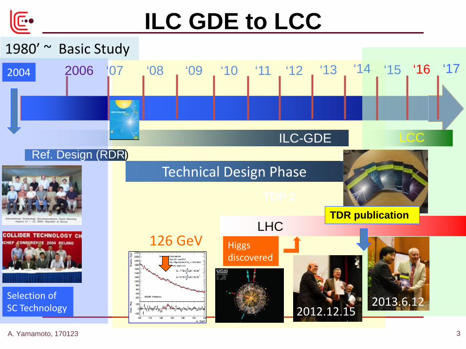
ILC GDE to LCC
Technical Design Phase
ILC-GDE
2006 ‘07 ‘08 ‘12 ‘09 ‘10 ‘11 ‘13
Higgs discovered
126 GeV
Selection of SC Technology
TDP 2
Ref. Design (RDR) LCC
LHC
2004
TDR
1980’ ~ Basic Study
2013.6.12 2012.12.15
TDR publication
‘14 ‘15 ‘16 ‘17
A. Yamamoto, 170123 3
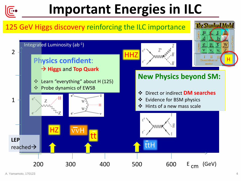
125 GeV Higgs discovery reinforcing the ILC importance
E cm (GeV) 200 300 400 500 600
Integrated Luminosity (ab-1)
1
2
HZ tt
HHZ
ttH
ννH
New Physics beyond SM: Direct or indirect DM searches Evidence for BSM physics Hints of a new mass scale
Physics confident: Higgs and Top Quark Learn “everything” about H (125) Probe dynamics of EWSB
K. Kawagoe (modified)
Important Energies in ILC
H
LEP reached
A. Yamamoto, 170123 4
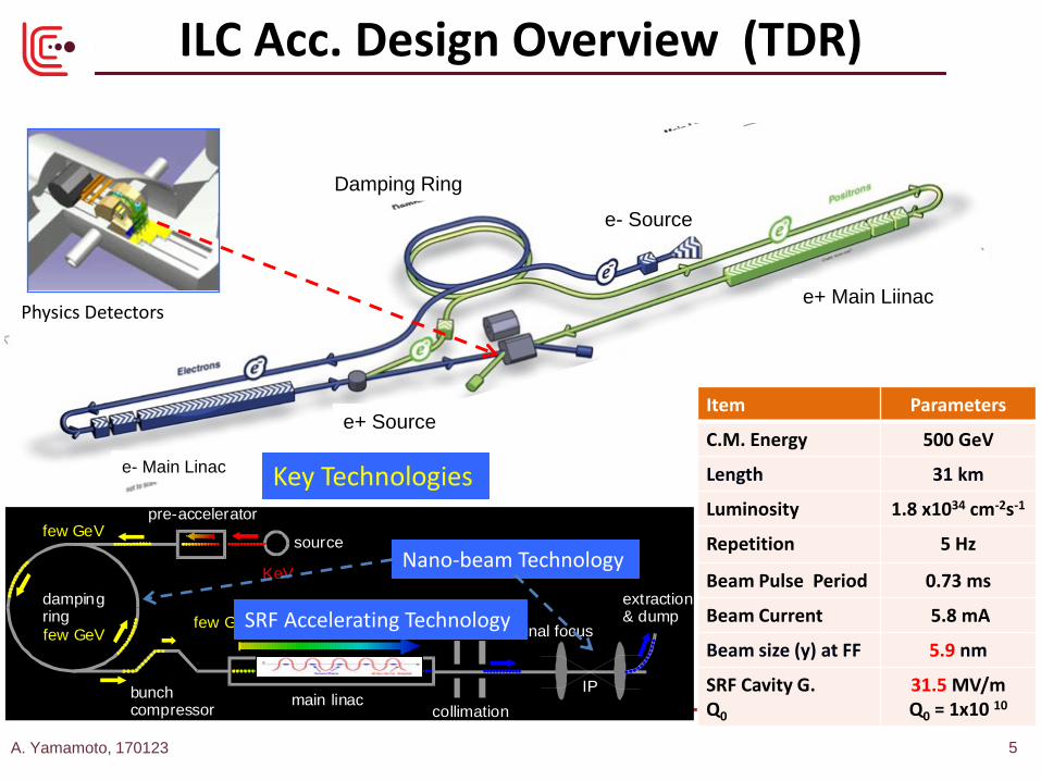
ILC Acc. Design Overview (TDR)
e- Source
e+ Main Liinac
e+ Source
e- Main Linac
Item Parameters
C.M. Energy 500 GeV
Length 31 km
Luminosity 1.8 x1034 cm-2s-1
Repetition 5 Hz
Beam Pulse Period 0.73 ms
Beam Current 5.8 mA
Beam size (y) at FF 5.9 nm
SRF Cavity G. Q0
31.5 MV/m Q0 = 1x10 10 main linacbunch
compressor
dampingring
source
pre-accelerator
collimation
final focus
IP
extraction& dump
KeV
few GeV
few GeVfew GeV
250-500 GeV
Nano-beam Technology
SRF Accelerating Technology
Key Technologies
Physics Detectors
Damping Ring
A. Yamamoto, 170123 5
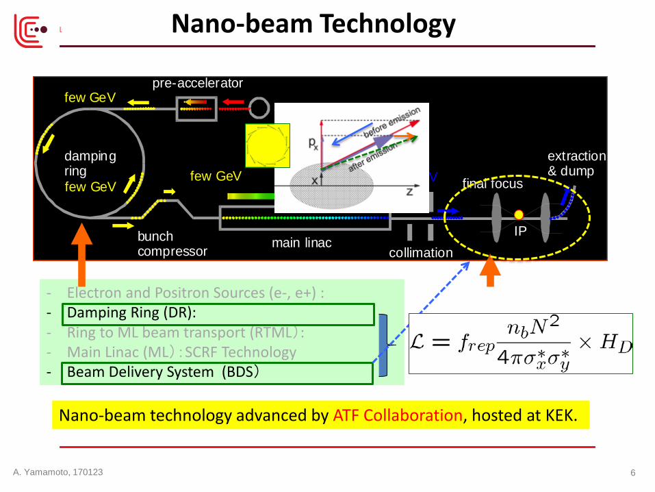
main linacbunchcompressor
dampingring
source
pre-accelerator
collimation
final focus
IP
extraction& dump
KeV
few GeV
few GeVfew GeV
250-500 GeV
Nano-beam Technology
- Electron and Positron Sources (e-, e+) : - Damping Ring (DR): - Ring to ML beam transport (RTML): - Main Linac (ML):SCRF Technology - Beam Delivery System (BDS)
Nano-beam technology advanced by ATF Collaboration, hosted at KEK.
A. Yamamoto, 170123 6

main linacbunchcompressor
dampingring
source
pre-accelerator
collimation
final focus
IP
extraction& dump
KeV
few GeV
few GeVfew GeV
250-500 GeV
SRF Technology
- Electron and Positron Sources (e-, e+) : - Damping Ring (DR): - Ring to ML beam transport (RTML): - Main Linac (ML):SCRF Technology - Beam Delivery System (BDS)
SRF Technology
A. Yamamoto, 170123 7
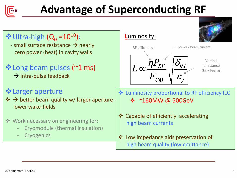
Ultra-high (Q0 =1010): - small surface resistance nearly zero power (heat) in cavity walls Long beam pulses (~1 ms) intra-pulse feedback Larger aperture better beam quality w/ larger aperture - lower wake-fields Work necessary on engineering for:
- Cryomodule (thermal insulation) - Cryogenics
Luminosity:
RF efficiency RF power / beam current
Vertical emittance
(tiny beams)
Luminosity proportional to RF efficiency ILC ~160MW @ 500GeV
Capable of efficiently accelerating high beam currents
Low impedance aids preservation of high beam quality (low emittance)
Advantage of Superconducting RF
A. Yamamoto, 170123 8
Introduction Technical Progress and Status
‒ Nano-beam technology ‒ SRF technology ‒ Civil engineering
Readiness for the Project ‒ Further effort for the cost reduction and the R&Ds
Summary
Outline
A. Yamamoto, 170123 9
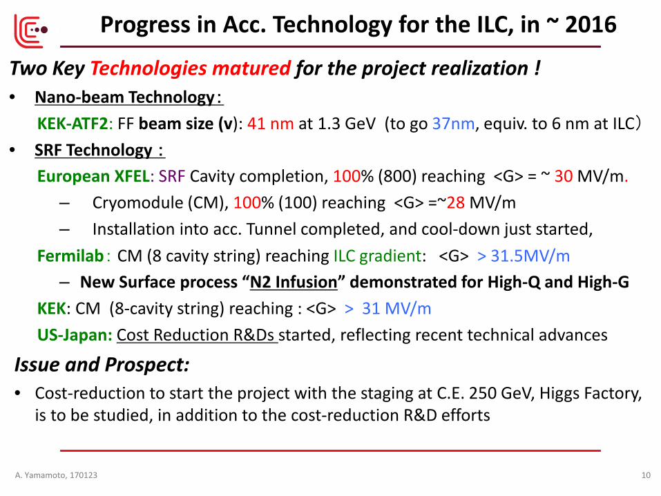
Two Key Technologies matured for the project realization ! • Nano-beam Technology:
KEK-ATF2: FF beam size (v): 41 nm at 1.3 GeV (to go 37nm, equiv. to 6 nm at ILC) • SRF Technology :
European XFEL: SRF Cavity completion, 100% (800) reaching <G> = ~ 30 MV/m. ‒ Cryomodule (CM), 100% (100) reaching <G> =~28 MV/m ‒ Installation into acc. Tunnel completed, and cool-down just started,
Fermilab: CM (8 cavity string) reaching ILC gradient: <G> > 31.5MV/m ‒ New Surface process “N2 Infusion” demonstrated for High-Q and High-G
KEK: CM (8-cavity string) reaching : <G> > 31 MV/m US-Japan: Cost Reduction R&Ds started, reflecting recent technical advances
Issue and Prospect: • Cost-reduction to start the project with the staging at C.E. 250 GeV, Higgs Factory,
is to be studied, in addition to the cost-reduction R&D efforts
Progress in Acc. Technology for the ILC, in ~ 2016
A. Yamamoto, 170123 10
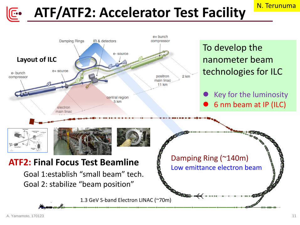
Layout of ILC To develop the nanometer beam technologies for ILC Key for the luminosity 6 nm beam at IP (ILC)
ATF/ATF2: Accelerator Test Facility
1.3 GeV S-band Electron LINAC (~70m)
Damping Ring (~140m) Low emittance electron beam ATF2: Final Focus Test Beamline
Goal 1:establish “small beam” tech. Goal 2: stabilize “beam position”
N. Terunuma
A. Yamamoto, 170123 11
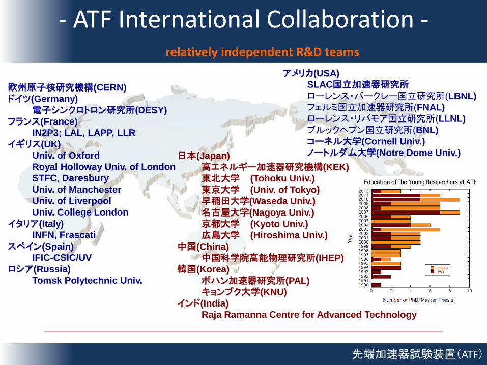
- ATF International Collaboration -
先端加速器試験装置(ATF)
欧州原子核研究機構(CERN) ドイツ(Germany) 電子シンクロトロン研究所(DESY) フランス(France) IN2P3; LAL, LAPP, LLR イギリス(UK) Univ. of Oxford Royal Holloway Univ. of London STFC, Daresbury Univ. of Manchester Univ. of Liverpool Univ. College London イタリア(Italy) INFN, Frascati スペイン(Spain) IFIC-CSIC/UV ロシア(Russia) Tomsk Polytechnic Univ.
日本(Japan) 高エネルギー加速器研究機構(KEK) 東北大学 (Tohoku Univ.) 東京大学 (Univ. of Tokyo) 早稲田大学(Waseda Univ.) 名古屋大学(Nagoya Univ.) 京都大学 (Kyoto Univ.) 広島大学 (Hiroshima Univ.) 中国(China) 中国科学院高能物理研究所(IHEP) 韓国(Korea) ポハン加速器研究所(PAL) キョンプク大学(KNU) インド(India) Raja Ramanna Centre for Advanced Technology
アメリカ(USA) SLAC国立加速器研究所 ローレンス・バークレー国立研究所(LBNL) フェルミ国立加速器研究所(FNAL) ローレンス・リバモア国立研究所(LLNL) ブルックヘブン国立研究所(BNL) コーネル大学(Cornell Univ.) ノートルダム大学(Notre Dome Univ.)
relatively independent R&D teams
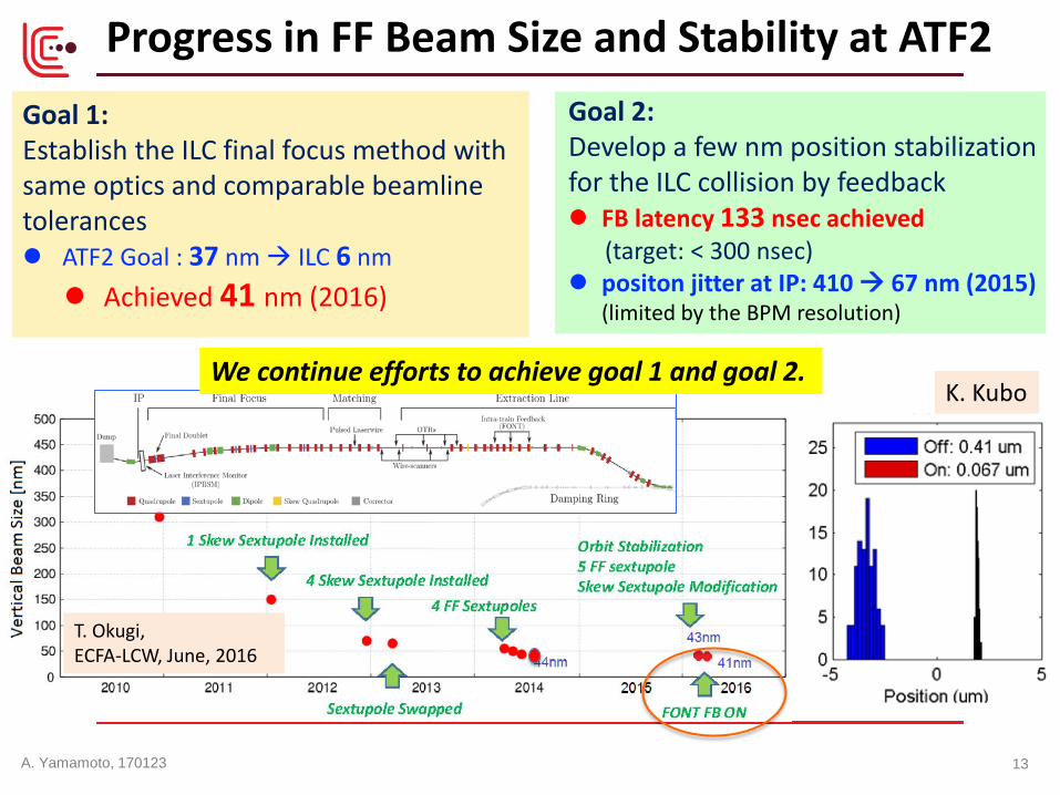
Goal 1: Establish the ILC final focus method with same optics and comparable beamline tolerances ATF2 Goal : 37 nm ILC 6 nm Achieved 41 nm (2016)
Progress in FF Beam Size and Stability at ATF2 Goal 2: Develop a few nm position stabilization for the ILC collision by feedback FB latency 133 nsec achieved (target: < 300 nsec) positon jitter at IP: 410 67 nm (2015)
(limited by the BPM resolution)
T. Okugi, ECFA-LCW, June, 2016
K. Kubo We continue efforts to achieve goal 1 and goal 2.
A. Yamamoto, 170123 13
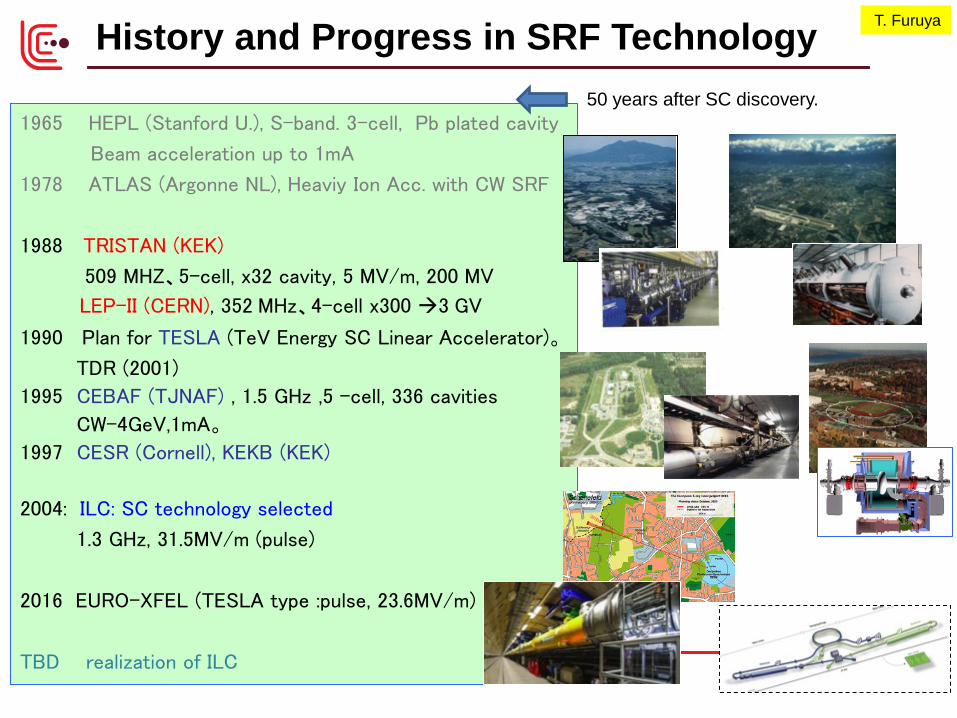
1965 HEPL (Stanford U.), S-band. 3-cell, Pb plated cavity
Beam acceleration up to 1mA
1978 ATLAS (Argonne NL), Heaviy Ion Acc. with CW SRF
1988 TRISTAN (KEK)
509 MHZ、5-cell, x32 cavity, 5 MV/m, 200 MV
LEP-II (CERN), 352 MHz、4-cell x300 3 GV
1990 Plan for TESLA (TeV Energy SC Linear Accelerator)。
TDR (2001)
1995 CEBAF (TJNAF) , 1.5 GHz ,5 –cell, 336 cavities
CW-4GeV,1mA。
1997 CESR (Cornell), KEKB (KEK)
2004: ILC: SC technology selected
1.3 GHz, 31.5MV/m (pulse)
2016 EURO-XFEL (TESLA type :pulse, 23.6MV/m)
TBD realization of ILC
History and Progress in SRF Technology T. Furuya
50 years after SC discovery.
CHESS at Cornell
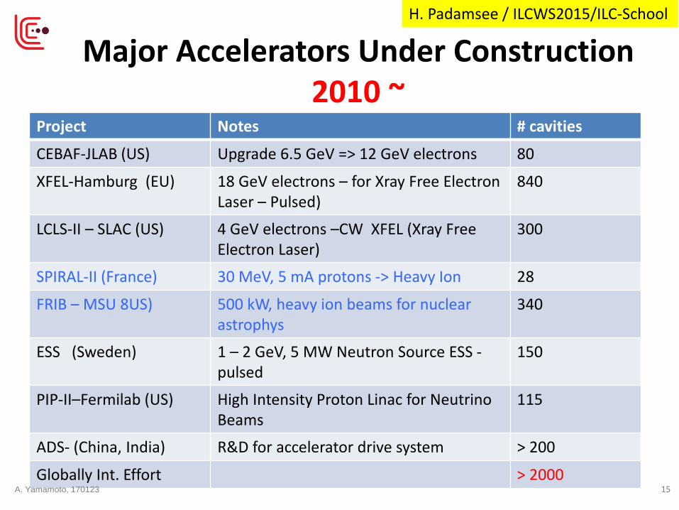
Major Accelerators Under Construction 2010 ~
Project Notes # cavities
CEBAF-JLAB (US) Upgrade 6.5 GeV => 12 GeV electrons 80
XFEL-Hamburg (EU) 18 GeV electrons – for Xray Free Electron Laser – Pulsed)
840
LCLS-II – SLAC (US) 4 GeV electrons –CW XFEL (Xray Free Electron Laser)
300
SPIRAL-II (France) 30 MeV, 5 mA protons -> Heavy Ion 28
FRIB – MSU 8US) 500 kW, heavy ion beams for nuclear astrophys
340
ESS (Sweden) 1 – 2 GeV, 5 MW Neutron Source ESS - pulsed
150
PIP-II–Fermilab (US) High Intensity Proton Linac for Neutrino Beams
115
ADS- (China, India) R&D for accelerator drive system > 200
Globally Int. Effort > 2000
H. Padamsee / ILCWS2015/ILC-School
A. Yamamoto, 170123 15
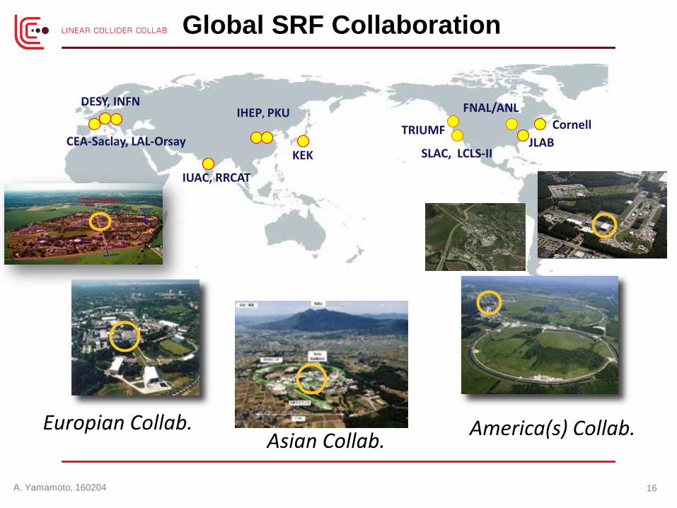
Global SRF Collaboration
Europian Collab. Asian Collab. America(s) Collab.
FNAL/ANL Cornell
JLAB KEK
DESY, INFN
SLAC, LCLS-II CEA-Saclay, LAL-Orsay
IHEP, PKU
IUAC, RRCAT
16
TRIUMF
A. Yamamoto, 160204

European XFEL: SRF Completed
1.3 GHz / 23.6 MV/m 800+4 SRF acc. Cavities 100+3 Cryo-Modules (CM)
Progress: 2013: Construction started 2015: SRF cav. (100%) completed CM (70%) progressed Further Plan: 2016: E- XFEL acc. completion 2016/E: E-XFEL beam to start Acc. : ~ 1/10 scale to ILC-ML SRF system: ~ 1/20 scale to ILC-SRF
XFEL
DESY
XFEL site DESY
Media.xfel.au, Dec. 2015
1 km SRF Linac
17

SRF cavity production/test ; # RI Cavities, 373 (as of Sept. 2015)
‒ Final process: 40 µm EP. ‒ w/ same recipe to ILC-SRF’s
‒ Tested at DESY-AMTF Notes::
‒ “Ultra-pure water rinsing as the 2nd process improving the gradient performance (> ~10%) for lower-performed cavities (not shown here).
E-XFEL: SRF Cavity Performance (as received) N. Walker, D. Reschke, SRF’15
G-max G-usable
G-usable (Q0> 1010 ) G-max (ILC)
<G> MV/m 29.4 33 (35) Yield at 28MV/m 66% 86% (90%)
A. Yamamoto, 170123 18
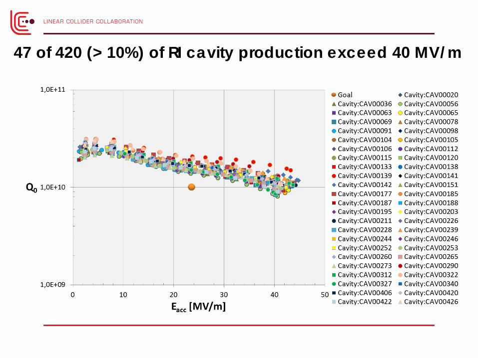
47 of 420 (> 10%) of RI cavity production exceed 40 MV/m

No degradation, after ~ XM54
O. Napoly, TTC2016
A. Yamamoto, 170123 20

Fermilab:CM2 reached <31.5 MV/m >
Cryomodule test at Fermilab reached < 31。5 > MV/m, exceeding ILC specification
E. Harms, TTC2014
ILC Milestone 31.5 MV/m
A. Yamamoto, 170123 21
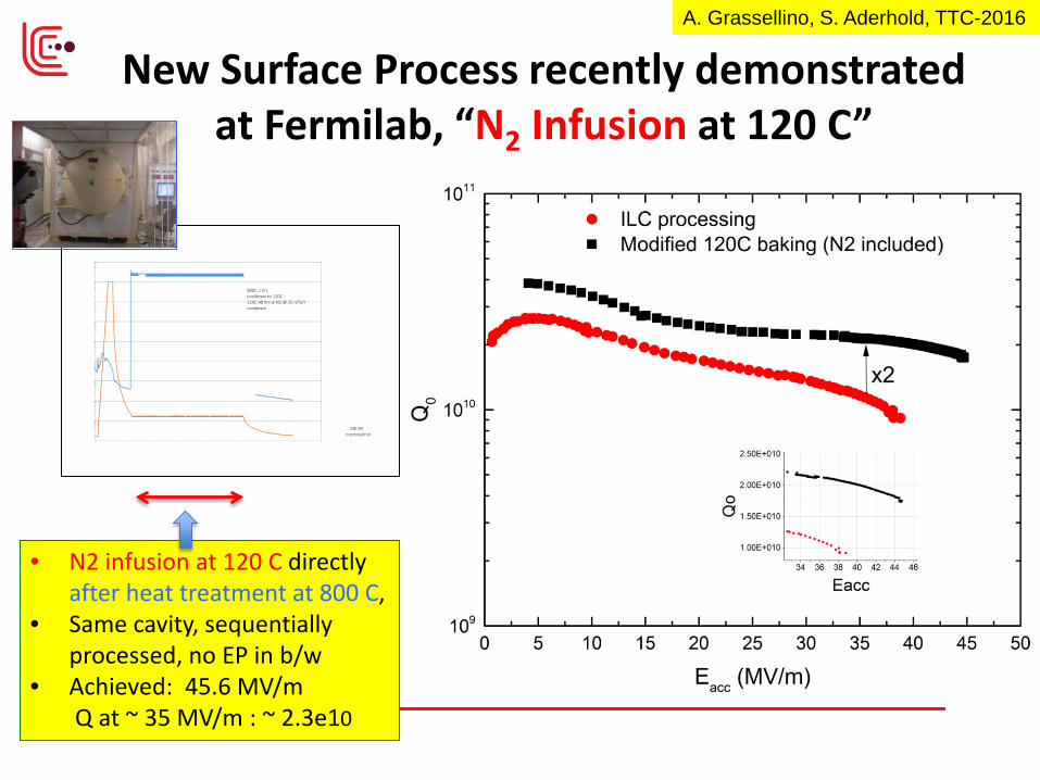
New Surface Process recently demonstrated at Fermilab, “N2 Infusion at 120 C”
• N2 infusion at 120 C directly after heat treatment at 800 C,
• Same cavity, sequentially processed, no EP in b/w
• Achieved: 45.6 MV/m Q at ~ 35 MV/m : ~ 2.3e10
A. Grassellino, S. Aderhold, TTC-2016

KEK-STF: Cavity/CM Performance, and RF and Beam Test Preparation
FY14: CM1+CM2a (8+4) assembly FY15: Cavity individually tested in CM RF power system in preparation FY16: 8-cavity string to be RF tested FY17: Beam Acceleration expected (to reach > 250 MeV )
SRF cavity Gradient (MV/m) before/after CM Assembly Module CM1a CM1b CM2a Cav. # 1 2 3 4 5 6 7 8 9 10 11 12 V. Test (CW) 37 36 38 36 37 35 39 36 12 36 32 32
in CM (pulse) 39 37 35 36 26 16 26 32 18 34 33 32
Gradient stable Degraded Gradient stable
*<G> : 30 MV /m (12 Cav.) , 35 MV/m (best 8)
Y. Yamamoto, E. Kako, H. Hayano
A. Yamamoto, 170123 23

8 Cavities Operation by Vector-Sum @31MV/m (2016)
8 Cavities were tuned on resonance by piezo, and vector-sum operation was done at 31MV/m.
Preliminary result Shin MICHIZONO, ACFA, Jan.19 2017
13
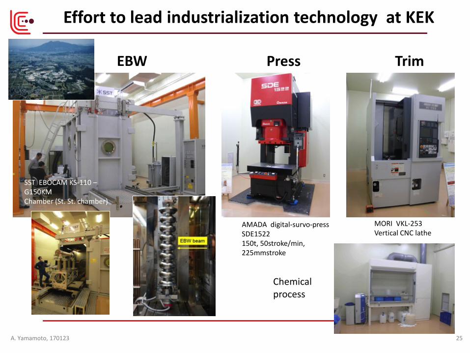
Effort to lead industrialization technology at KEK
EBW Press Trim
AMADA digital-survo-press SDE1522 150t, 50stroke/min, 225mmstroke
MORI VKL-253 Vertical CNC lathe
Chemical process
SST EBOCAM KS-110 – G150KM Chamber (St. St. chamber)
A. Yamamoto, 170123 25
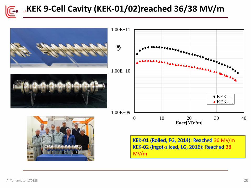
KEK 9-Cell Cavity (KEK-01/02)reached 36/38 MV/m
36 MV/m 38
MV/m
1.00E+09
1.00E+10
1.00E+11
0 10 20 30 40Q
0 Eacc[MV/m]
KEK-…KEK-…
A. Yamamoto, 170123 26

ILC 1.3 GHz SCRF R&D at IHEP
2012
2010
2008
2014
single cell low-loss large and fine cavity, max. 40 MV/m by CP, process and test at KEK
9-cell low-loss, large grain cavity without HOM, 20 MV/m by CP, test at KEK and JLAB
9-cell Low Loss, large grain cavity with HOM, 20 MV/m by EP, process and test at FNAL
9-cell TESLA-like, fine grain cavity with HOM, 16.8 MV/m by EP, process and test at KEK
IHEP-01
IHEP-02
IHEP-03
9-cell TESLA, fine grain cavity with HOM, by High-Energy Racing, process and test at KEK
2016
HERT001
IHEP ILC-TC1
2016/12/06
J. Zhai (IHEP), LCWS-2016
27
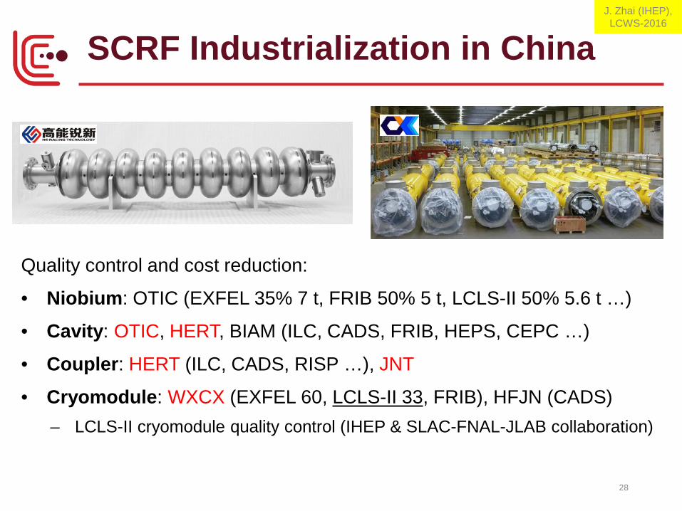
SCRF Industrialization in China
28
Quality control and cost reduction:
• Niobium: OTIC (EXFEL 35% 7 t, FRIB 50% 5 t, LCLS-II 50% 5.6 t …)
• Cavity: OTIC, HERT, BIAM (ILC, CADS, FRIB, HEPS, CEPC …)
• Coupler: HERT (ILC, CADS, RISP …), JNT
• Cryomodule: WXCX (EXFEL 60, LCLS-II 33, FRIB), HFJN (CADS) – LCLS-II cryomodule quality control (IHEP & SLAC-FNAL-JLAB collaboration)
J. Zhai (IHEP), LCWS-2016
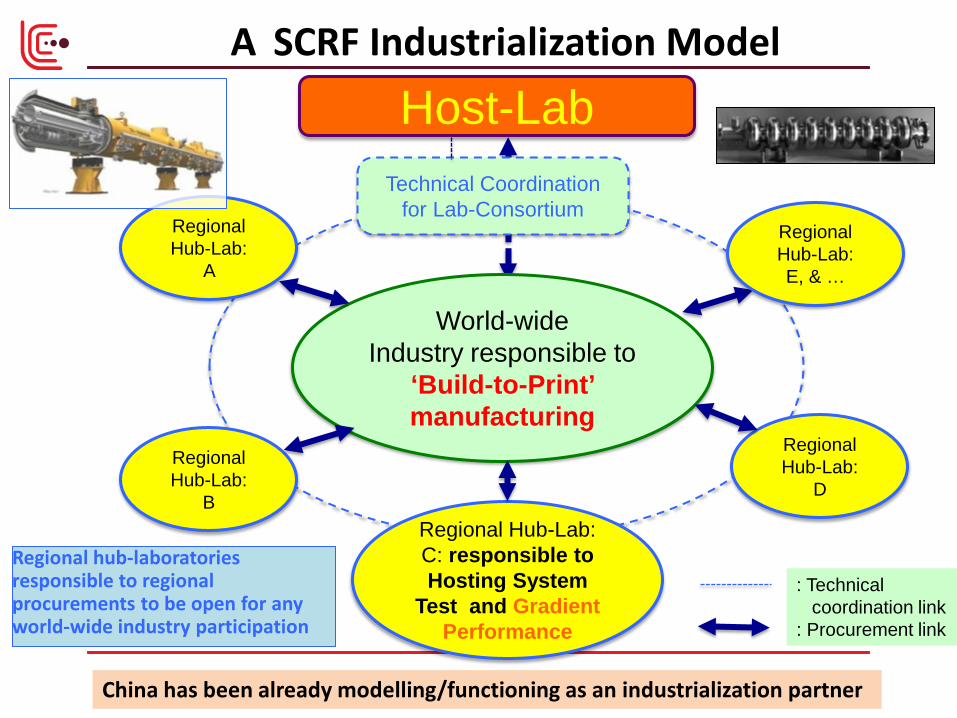
A SCRF Industrialization Model
Regional hub-laboratories responsible to regional procurements to be open for any world-wide industry participation
Regional Hub-Lab: E, & …
Regional Hub-Lab:
A
Regional Hub-Lab:
B
Regional Hub-Lab:
D
World-wide Industry responsible to
‘Build-to-Print’ manufacturing
Host-Lab
Regional Hub-Lab: C: responsible to Hosting System
Test and Gradient Performance
Technical Coordination for Lab-Consortium
: Technical coordination link : Procurement link
29 China has been already modelling/functioning as an industrialization partner
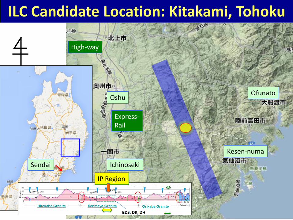
ILC Candidate Location: Kitakami, Tohoku
Oshu
Ichinoseki
Ofunato
Kesen-numa
Sendai
Express- Rail
High-way
IP Region
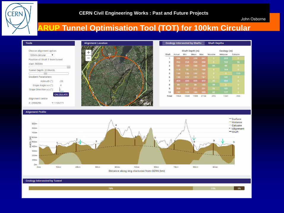
CERN Civil Engineering Works : Past and Future Projects John Osborne
ARUP Tunnel Optimisation Tool (TOT) for 100km Circular
Lake Geneva Rhone
Les Usses
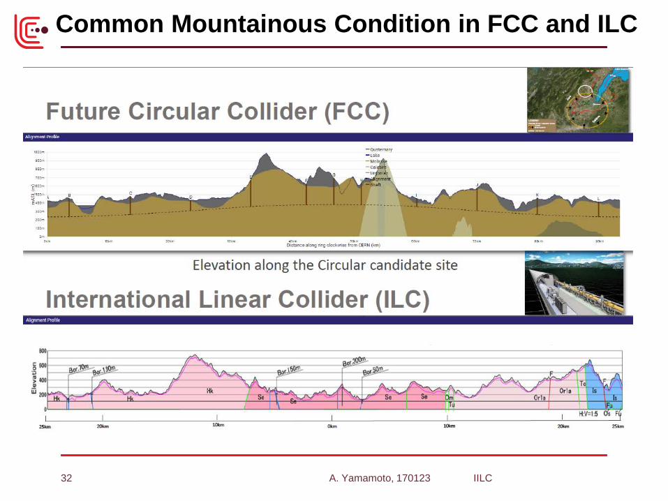
Common Mountainous Condition in FCC and ILC
A. Yamamoto, 170123 IILC 32
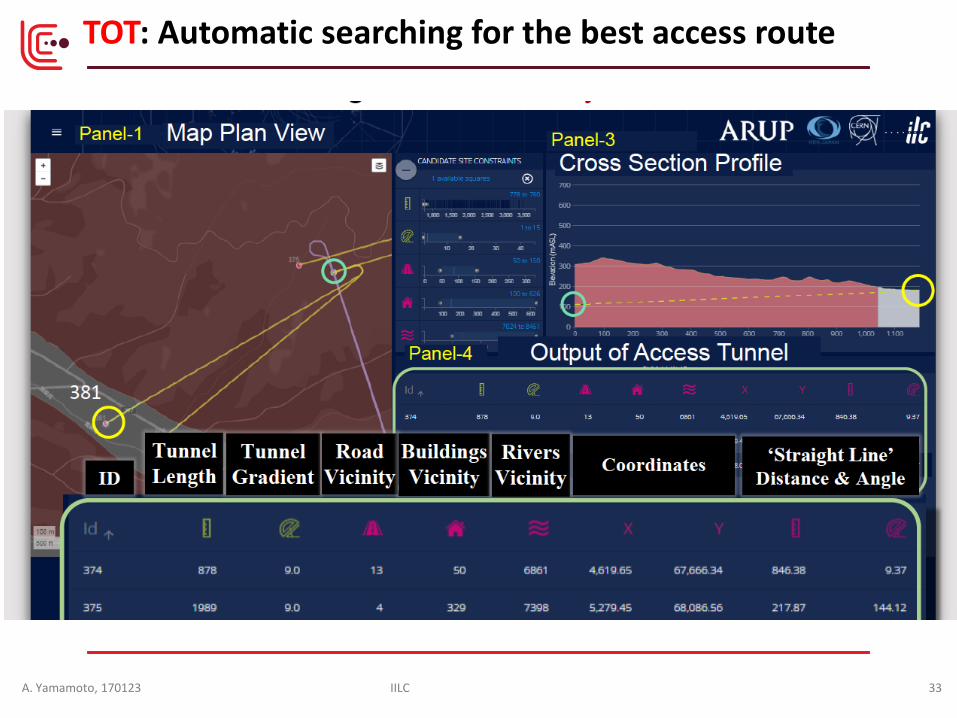
TOT: Automatic searching for the best access route
A. Yamamoto, 170123 IILC 33

Visualization of TOT-ILC
A. Yamamoto, 170123 IILC 34

New Baselining of Civil-engineering,
Beam Line
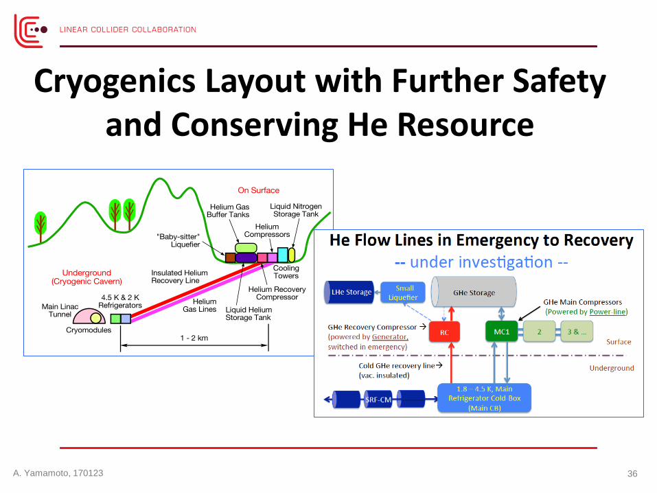
Cryogenics Layout with Further Safety and Conserving He Resource
A. Yamamoto, 170123 36
Introduction Technical Progress and Status
‒ Nano-beam technology ‒ SRF technology ‒ Civil engineering
Readiness for the Project ‒ Further effort for the cost reduction and the R&Ds
Summary
Outline
A. Yamamoto, 170123 37
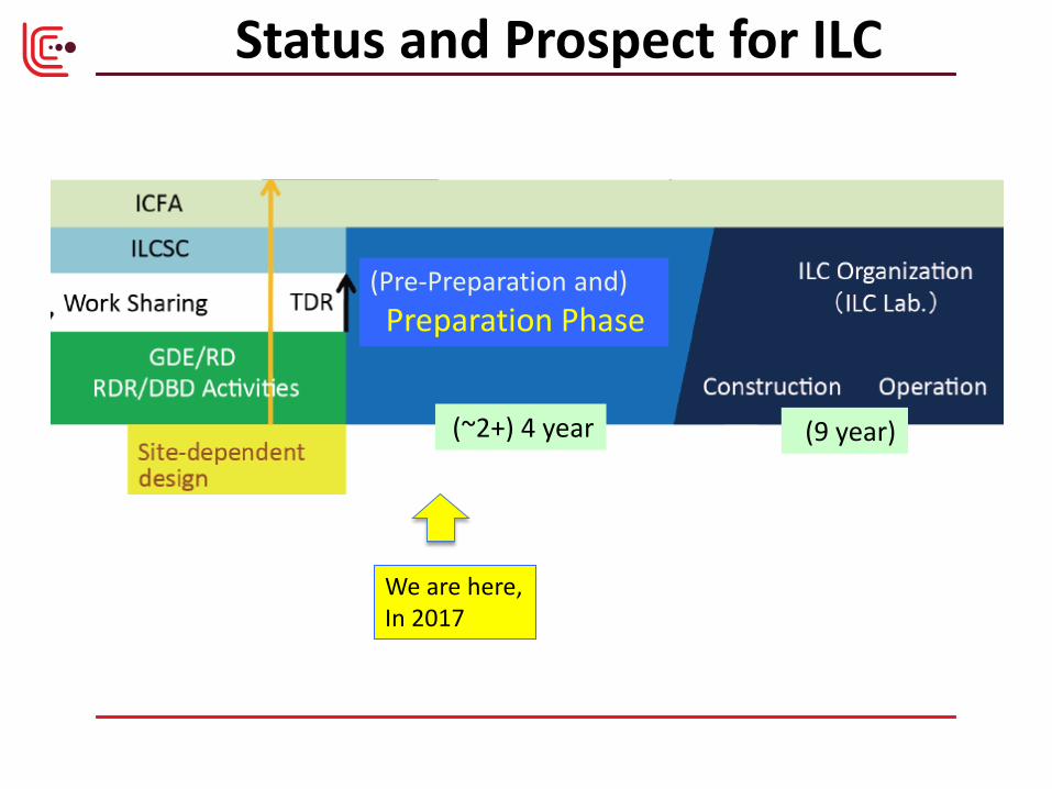
Status and Prospect for ILC
We are here, In 2017
(~2+) 4 year
(Pre-Preparation and) Preparation Phase
(9 year)
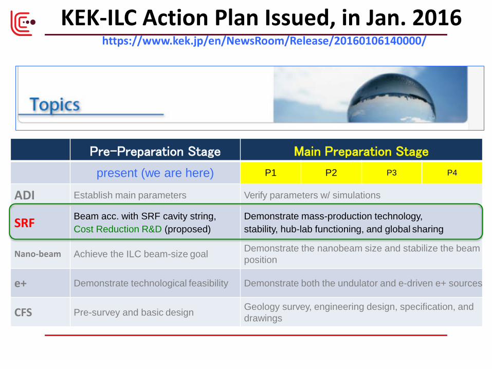
KEK-ILC Action Plan Issued, in Jan. 2016 https://www.kek.jp/en/NewsRoom/Release/20160106140000/
Pre-Preparation Stage Main Preparation Stage
present (we are here) P1 P2 P3 P4
ADI Establish main parameters Verify parameters w/ simulations
SRF Beam acc. with SRF cavity string, Cost Reduction R&D (proposed)
Demonstrate mass-production technology, stability, hub-lab functioning, and global sharing
Nano-beam Achieve the ILC beam-size goal Demonstrate the nanobeam size and stabilize the beam position
e+ Demonstrate technological feasibility Demonstrate both the undulator and e-driven e+ sources
CFS Pre-survey and basic design Geology survey, engineering design, specification, and drawings
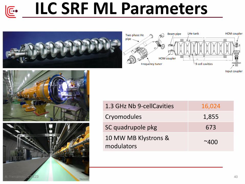
1.3 GHz Nb 9-cellCavities 16,024 Cryomodules 1,855 SC quadrupole pkg 673 10 MW MB Klystrons & modulators ~400
ILC SRF ML Parameters
A. Yamamoto, 170123 40

A plan for ILC Cost-Reduction R&D in Japan and US focusing on SRF Technology, in 2~3 years
Based on recent advances in technologies; • Nb material preparation - w/ optimum RRR and clean surface
• SRF cavity fabrication for high-Q and high-G -w/ a new baking recipe provided by Fermilab
• Power input coupler fabrication - w/ new (low SEE) ceramic without coating
• Cavity chemical process - w/ vertical EP and new chemical (non HF) solution
• Others
S. Michizono, S. Belomestnykh

FG-Nb rolled or LG-Nb sliced from Ingot
Cleanness highly secured
Courtesy: G. Myneni
A. Yamamoto, 170123 43
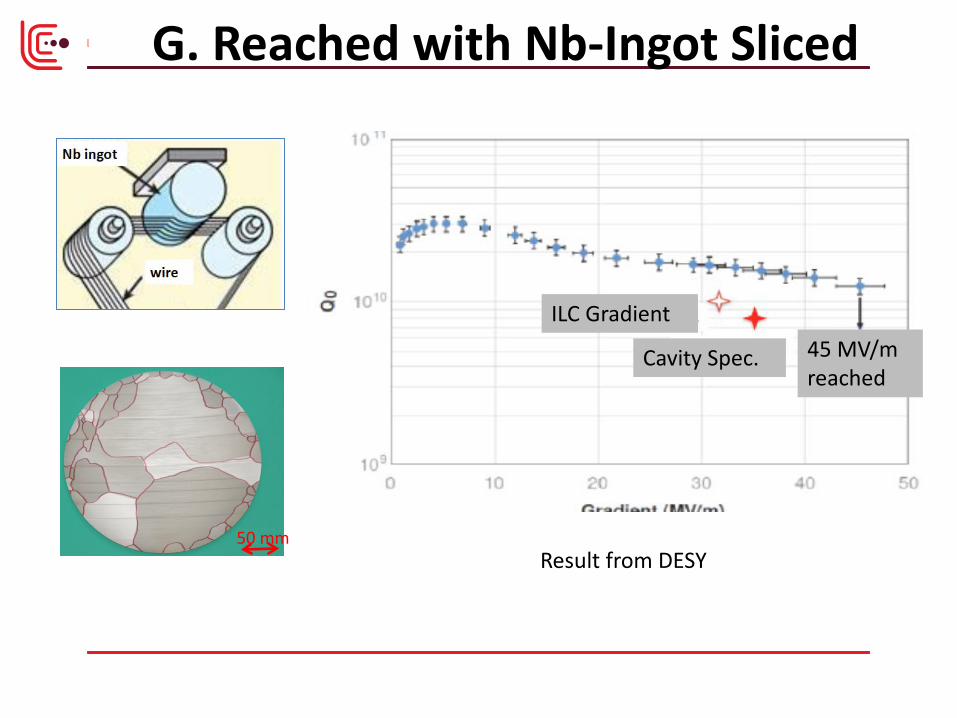
G. Reached with Nb-Ingot Sliced
50 mm
ILC Gradient
Cavity Spec. 45 MV/m reached
Result from DESY

Standard Procedure Established Standard Fabrication/Process
Fabrication Nb-sheet purchasing
Component Fabrication
Cavity assembly with EBW
Process EP-1 (~150um)
Ultrasonic degreasing with detergent, or ethanol rinse
High-pressure pure-water rinsing
Hydrogen degassing at > 800 C
Field flatness tuning
EP-2 (~20um)
Ultrasonic degreasing or ethanol (or EP 5 um with fresh acid)
High-pressure pure-water rinsing
Antenna Assembly
Baking at 120 C
Cold Test (vertical test)
Performance Test with temperature and mode measurement
Key Process Fabrication • Material • EBW • Shape
Process • Electro-Polishing
• Ethanol Rinsing or • Ultra sonic. + Detergent
Rins.
• High Pr. Pure Water cleaning
• N2 infusion at 120 C directly
after heat treatment at 800 C
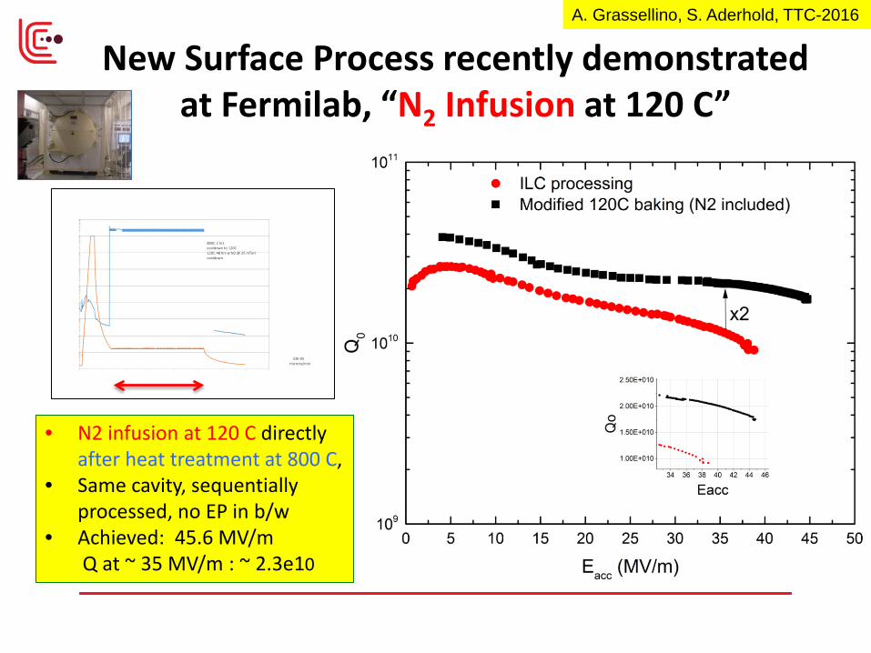
New Surface Process recently demonstrated at Fermilab, “N2 Infusion at 120 C”
• N2 infusion at 120 C directly after heat treatment at 800 C,
• Same cavity, sequentially processed, no EP in b/w
• Achieved: 45.6 MV/m Q at ~ 35 MV/m : ~ 2.3e10
A. Grassellino, S. Aderhold, TTC-2016
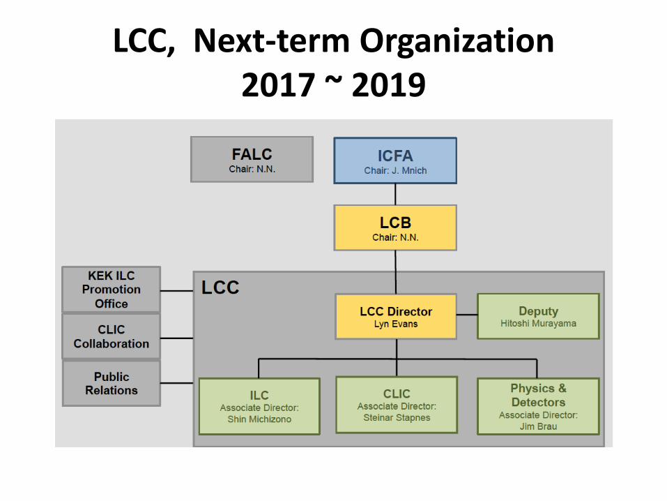
LCC, Next-term Organization 2017 ~ 2019
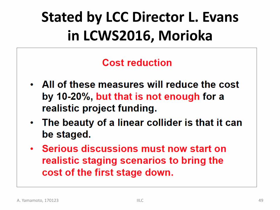
Stated by LCC Director L. Evans in LCWS2016, Morioka
A. Yamamoto, 170123 IILC 49
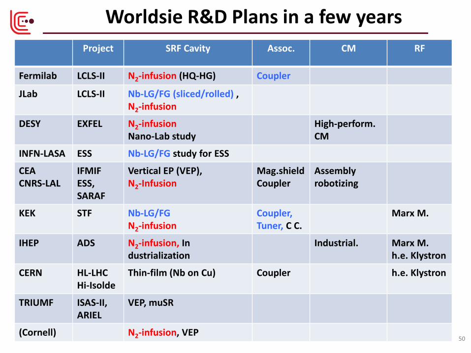
Worldsie R&D Plans in a few years Project SRF Cavity Assoc. CM RF
Fermilab LCLS-II N2-infusion (HQ-HG) Coupler
JLab LCLS-II Nb-LG/FG (sliced/rolled) , N2-infusion
DESY EXFEL N2-infusion Nano-Lab study
High-perform. CM
INFN-LASA ESS Nb-LG/FG study for ESS
CEA CNRS-LAL
IFMIF ESS, SARAF
Vertical EP (VEP), N2-Infusion
Mag.shield Coupler
Assembly robotizing
KEK STF Nb-LG/FG N2-infusion
Coupler, Tuner, C C.
Marx M.
IHEP ADS N2-infusion, In dustrialization
Industrial. Marx M. h.e. Klystron
CERN HL-LHC Hi-Isolde
Thin-film (Nb on Cu) Coupler h.e. Klystron
TRIUMF ISAS-II, ARIEL
VEP, muSR
(Cornell) N2-infusion, VEP 50
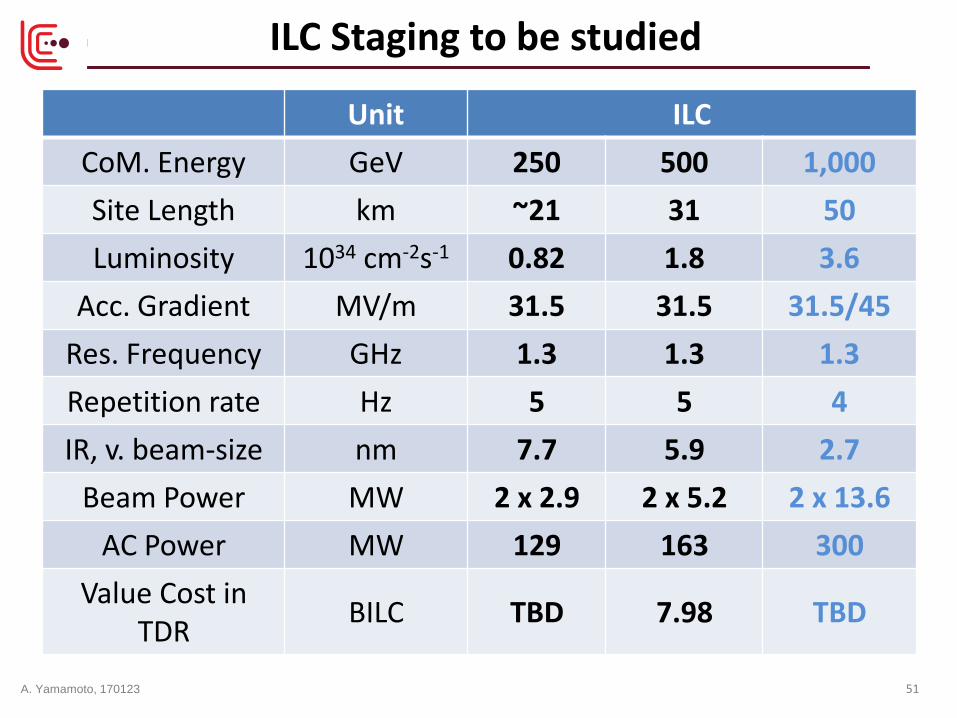
ILC Staging to be studied
Unit ILC CoM. Energy GeV 250 500 1,000 Site Length km ~21 31 50 Luminosity 1034 cm-2s-1 0.82 1.8 3.6
Acc. Gradient MV/m 31.5 31.5 31.5/45 Res. Frequency GHz 1.3 1.3 1.3 Repetition rate Hz 5 5 4 IR, v. beam-size nm 7.7 5.9 2.7
Beam Power MW 2 x 2.9 2 x 5.2 2 x 13.6 AC Power MW 129 163 300
Value Cost in TDR BILC TBD 7.98 TBD
A. Yamamoto, 170123 51
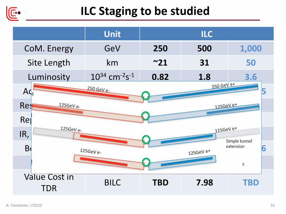
ILC Staging to be studied
Unit ILC CoM. Energy GeV 250 500 1,000 Site Length km ~21 31 50 Luminosity 1034 cm-2s-1 0.82 1.8 3.6
Acc. Gradient MV/m 31.5 31.5 31.5/45 Res. Frequency GHz 1.3 1.3 1.3 Repetition rate Hz 5 5 4 IR, v. beam-size nm 7.7 5.9 2.7
Beam Power MW 2 x 2.9 2 x 5.2 2 x 13.6 AC Power MW 129 163 300
Value Cost in TDR BILC TBD 7.98 TBD
A. Yamamoto, 170123 52

• ILC prepared for an e+e- collider, CE 500 GeV, extendable to 1 TeV.
• Nano-Beam technology demonstrated at ATF hosted at KEK
• SRF Technology advanced, and, particularly, demonstrated at E- XFEL for mass-production, and at Fermilab for High-Q and High-G.
• Cryogenics & Civil Eng/ works advanced, reflecting CERN-LHC exp.
• Cost Reduction R&D work required for SRF technologies, reflecting recent technology progress,
• Study of the energy staging, starting at C.E. 250 GeV, to be studied for realizing the project sooner.
Summary
A. Yamamoto, 170123 53

54
reserved
A. Yamamoto, 170123

Linear Collider Collaboration (LCC) Global Structure

Progress Courtesy: G. Ciovati, R. Geng
G. Ciovati IPAC’13 THYB201
A. Yamamoto, 170123 56

Björn Wiik vision
Under construction
Under construction
TDR by 2012
R&D needed
ITRP Recommendation
Progress/Prospect in SRF Cavity Gradient for Frontier Particle Accelerators
TRISTAN, LEP, KEKB
R. Geng