international journal of scientific & … · the traditional system for conversions of...
TRANSCRIPT

INTERNATIONAL JOURNAL OF SCIENTIFIC & TECHNOLOGY RESEARCH VOLUME 6, ISSUE 01, JANUARY 2017 ISSN 2277-8616
128 IJSTR©2017 www.ijstr.org
Intelligent Control Of An Electric Vehicle (ICEV)
Taoufik Chaouachi, Kamel Jemaï
Abstract: The electric vehicle allows fast, gentle, quiet and environmentally friendly movements in industrial and urban environments. The automotive industry has seen the opportunity to revive its production by replacing existing vehicles due to the reluctance of oil reserves around the world. In order to greatly reduce countries' dependence on oil, strategic sectors such as transport must increasingly integrate technologies based primarily on clean and renewable energy. Governments must implement large-scale measures to equip themselves with electric vehicles and build large recharge networks. The traditional system for conversions of conventional vehicles into electric vehicles consists of replacing the internal combustion engine and the gearbox with electrical components (engine and gearbox, or engine and gearbox), retaining the rest of the elements Transmission (transmission shafts, etc.). Index Terms: Strategy of control, random perturbation method , fuzzy logic,power train vehicle,electric vehicle,Permanent magnetic synchronus motor.
————————————————————
1 INTRODUCTION Reducing CO emissions represents a challenge for the transport sector. Transportation produces approximately 23 percent of the global CO emissions from fuel combustion. With rapid urbanization in developing countries, energy consumption and CO emissions by urban transport are increasing quickly[18]. Over the last few decades, the environmental impact of oil transport infrastructure, combined with the reluctance of energy resources, has led to renewed interest in an electric transport infrastructure. Electric vehicles differ from fossil fuel vehicles in that the electricity they consume can be produced from a wide range of sources, including fossil fuels, nuclear power and renewable Tidal energy, solar and wind energy or any combination of these. The energy consumption of these electric vehicles varies according to the fuel and the technologies used to produce electricity. Electricity can then be stored in the vehicle using an on-board battery[1], [5]. The electric motors are mechanically simple and often achieve high energy conversion efficiencies over the whole range of speed and power developed and can be controlled with high accuracy. They can also be combined with regenerative braking systems that have the ability to convert motion energy into stored electricity. This can be used to reduce brake system wear and reduce total energy consumption. Electric motors can be finely controlled and provide high starting torque, unlike internal combustion engines, and do not require multiple gears to match power curves. This eliminates the need for gearboxes and torque converters. Electric vehicles offer silent and smooth operation and therefore have less noise and vibration than internal combustion engines. In this work, we have incorporated new strategies for controlling the state variables of an electric vehicle based on fuzzy controllers. We attached particular importance to the mechanical transmission system by means of an appropriate modeling of the symbiosis between the electrical management system and the mechanical management system.
2 FUZZY STRATEGY
2.1 Fuzzy Studied Model The topology of each fuzzy controller to integrate, was based on an interaction between two input variables, characterized successively by an error xMi and an
instantaneous variation of the error xMi/ t , to synthesize
a fuzzy vector KxMi [6], [7],[8].
Fig.1.Model of a fuzzy controller
We defined the degree of membership of the error ix
to a
membership function rmfunc
by
ix
rmfunc
and t
ix
rmfunc
the degree of membership of the error variation to another membership function [18]. Let then:
tmfuncmfuncR
ix
r
ix
rk
. (1)
Fig.2. Rulers treatment
A surface kRS swept by the control vector for a rule kR
is given by: ix
K

INTERNATIONAL JOURNAL OF SCIENTIFIC & TECHNOLOGY RESEARCH VOLUME 6, ISSUE 01, JANUARY 2017 ISSN 2277-8616
129 IJSTR©2017 www.ijstr.org
rkkmfuncRRS .
(2)
Fig.3.Surface related to rule kR
Indeed, we have implemented a matrix of fuzzy inferences through a number of membership functions
iMF ,
Both for the error x ( 11x
N ), That for its variation
t
x
( 11
t
xN ) The same for the control vector fU (
11fUN ), [15].
Thus, the total number of fuzzy inferences is given by :
121.
t
règles xxNNN
(3) These membership functions are specified in the following table:
Table 1 : Membership functions
1 NTGMFMF 1
2 NGMFMF 2
3 NMFMF 3
4 NMMFMF 4
5 NPMFMF 5
6 6MF ZEMF
7 PPMFMF 7
8 PMMFMF 8
9 PMFMF 9
10 PGMFMF 10
11 PTGMFMF 11
where :
NTG : Negative Very Big,
NG : Negative Big,
N : Negative,
NM : Negative Medium ,
NP : Negative Small,
ZE : Zero,
PP : Positive Small ,
PM : Positif Medium,
P : Positif,
PG : Positif Big,
PTG : Positif Very Big.
The overall area swept by the fuzzy vector ix
K after use of
all the rules is formulated as follows :
k
kR
k
ix
R
Nk
k
R
KN
S
S
(4)
With : kRN number of rules that are used. Thus, the
fuzzy vector ix
K is none other than the abscissa of the
center of gravity of the overall surface ix
KS swept by the
control vector ix
K and deduced in accordance with the
relationship.
Fig.4. Total surface swept by the fuzzy control vector ix
K
1
1
1
1
ixixrkR
ixixixrkR
nf
ix
K).K(mfunc.
K.K).K(mfunc.K
(5)
Where :nf
xiK is an un-fuzzy vector.
2.2New Rescaling Technique A new technique of scaling will be of great importance for the magnitudes of the state variables that may possibly exceed the extreme limits quoted. In other words, all sizes
to be treated ix giving rise to an error
ix and a variation of

INTERNATIONAL JOURNAL OF SCIENTIFIC & TECHNOLOGY RESEARCH VOLUME 6, ISSUE 01, JANUARY 2017 ISSN 2277-8616
130 IJSTR©2017 www.ijstr.org
error t
ix
. Must undergo a transfer at the base of fuzzy
variables evidenced by the interval [-1,1] , to generate the fuzzy input required for processing by the designated controller in accordance with the following system of equations [9]:
)]([)]([
2
)]([)]([
2
]1[.
]1[.
minmax
minmax
tmfuncG
tmfuncG
B
mfuncGmfuncGB
Bt
Bt
BB
ixix
ixix
ixix
ixix
r
ss
r
sst
r
ss
r
ss
tt
f
f
(6) Where:
2
2
2
2
2
2
2
2
22
1
22
1
22
1
22
1
.
)t
(
exp...
min))t
(mfunc(G
.
)t
(
exp...
max))t
(mfunc(G
.
)(exp.
..min))(mfunc(G
.
)(exp.
..max))(mfunc(G
ix
ix
r
ss
min
ix
ix
r
ss
max
ix
ixr
ss
min
ix
ixr
ss
max
(7)
Where i i denote respectively the mean and standard
deviation of the error and variation of error ix and
t
ix
.
Similarly, the control vector ix
K must undergo a transfer to
the basic quantities studied, rescaled, to assign the valuenf
xiK and this means the system of equations:
2
)]([)]([
]1[.
minmax ii
nf
ix
nf
ixinf
ixi
xr
ss
xr
ss
K
KxK
nf
x
KmfuncGKmfuncGB
BKBK
(8)
Where:
2
2
2
2
22
1
22
1
ixK
ixKix
ixK
ixr
ss
min
ixK
ixKix
ixK
ixr
ss
max
.
)K(
exp...
min)]K(mfunc[G
.
)K(
exp...
max)]K(mfunc[G
(9)
Through this new technique of rescaling, we assigned a dynamic behavior to the fuzzy controller in order to ensure better tracking of the variable to control [9].
3ELECTRIC VEHICLE MODEL The model of the electric vehicle studied is illustrated in figure 2. We focus mainly on the components of the power system that provide electric traction namely[11], [14]: The photovoltaic panel, The buck converter, The battery, The DC-Link, The DC/AC converter, The filter, The permanent magnet synchronous machine (PMSM).
Fig.5. Model of the studied electric vehicle
4 PHOTOVOLTAIC GENERATOR We start with a reminder of the electrical equations of the integrated photovoltaic generator. We highlight the model of the basic component of this generator, namely the photovoltaic cell with a real model.
4.1 Real Model of a Photovoltaic Cell In order to highlight the physical phenomena that occur in the photovoltaic cell, we must consider: The leaks resulting from the edge effects of the junction
PN and this by the integration of a shunt resistor shR in
the equivalent scheme of the cell, The losses due to the contacts and the connections and
which will be modeled, in the equivalent diagram, by a series resistance Rs .
Fig.6. Real modelof a photovoltaic cell

INTERNATIONAL JOURNAL OF SCIENTIFIC & TECHNOLOGY RESEARCH VOLUME 6, ISSUE 01, JANUARY 2017 ISSN 2277-8616
131 IJSTR©2017 www.ijstr.org
The current supplied by the photovoltaic cell is then:
sh
pspTV
pI.sRpV
sphpR
I.RVe.III
1
(10)
The current ccI supplied by the photovoltaic cell when the
latter has a zero voltage to these terminals ( VVp 0 ):
sh
ccsTV
ccI.sR
sphccR
I.Re.III
1
(11)
The voltage coV delivered by the photovoltaic cell when the
latter does not discharge any current ( AI p 0 ) is:
1
..
ssh
co
s
ph
TcoIR
V
I
ILnVV (12)
The optimum power opP delivered by the photovoltaic cell is
defined when it delivers an optimum current opI under an
optimum voltage opV :
opopopI.VP
(13)
Fig.7. Current voltage characteristic of a photovoltaic cell
4.2 Model Of A Photovoltaic Generator We present in the following the developed scheme of the model of a photovoltaic generator, figure 8.
Fig.8. Scheme of a photovoltaic generator
The current supplied by the photovoltaic generator is expressed as follows:
sh
pspVn
IRV
spphppR
IRVeInInI Ts
psp
.1...
.
.
(14)
Taking into account that:
sh
s
R
R 0 (15)
then:
1e.I.nI.nI Ts
psp
V.n
I.RV
spphpp
(16)
The photovoltaic generator then delivers energy to the rest of the power circuit of the electric vehicle as shown in figure 9.
Fig.9. Electric vehicle battery charging system
5 BUCK CONVERTER In order to ensure a conditioned transfer of the energy supplied by the photovoltaic generator ( Vp , Ip ) to the rest

INTERNATIONAL JOURNAL OF SCIENTIFIC & TECHNOLOGY RESEARCH VOLUME 6, ISSUE 01, JANUARY 2017 ISSN 2277-8616
132 IJSTR©2017 www.ijstr.org
of the power system of the electric vehicle, we have integrated a buck converter. In fact, by checking the duty cycle
buc of this converter, according to the requirement of
the PMSM motor, we identify the level of the requested
power of the photovoltaic (PV) generator. Let bucT be the
commutation cycle of the buck converter. From 0 to
bucbuc T. we have:
soc
p
bupV
dt
dI.LV
(17)
From bucbuc T. to bucT we have:
soc
p
buV
dt
dI.L 0
(18)
And thus:
minpbuc
buc
soc
pI)Tt.(
L
VI
(19)
On the other hand :
minpbucbuc
buc
soc
maxpIT)..(
L
VI
1
(20)
The current pI ripple noted pI is evaluated through the
relationship:
soc
bucbuc
buc
minpmaxppV.
f.LIII
1
(21)
Where :
buc
bucT
f1
Thus, we conclude that the average value of the voltage at the terminals of the storage battery
socV is expressed as a
function of the voltage applied by the photovoltaic generator
pV in accordance with the following relation:
pbucsocV.V
(22)
6 BATTERY MODEL The charge separation that takes place in each battery cell give rise to a cell voltage, orOpen Circuit Voltage, OCV. As
soon as the terminal ends are closed in an electrical circuit,chemical reactions start to take place in the cell, causing the flow of a current. However,due to the charge transport in the electrolyte, and the chemical reactions at the surfaceof the plates and the current in the plates, there is a resistance to the current, which iscalled the battery's internal resistance, R. A simple circuit model of a battery is depicted in Figure 10, where the OCV isdepending on the SOC, and the resistance is constant. There are, however, a number offactors that are not included in this simple model, such as the charge accumulation atthe plates, which gives capacitive contributions to the resistance, SOC and temperaturedependence of all parameters (OCV, R and C), and finally a self-discharge of the battery,that can be modeled as a shunt resistance to the OCV.
Fig.10. Electric vehicle battery
7 BOOST CONVERTER MODEL
The energy delivered by the storage battery ( bb IV , )must
meet the requirements imposed instantly, namely:
Maintain a DC link voltage level dcV required by the
operating point of the PMSM motor, Determine the level of desired reference voltages (
** , qcdc vv ) that the converterPMSMC must supply.
Fig.11. Boost converter

INTERNATIONAL JOURNAL OF SCIENTIFIC & TECHNOLOGY RESEARCH VOLUME 6, ISSUE 01, JANUARY 2017 ISSN 2277-8616
133 IJSTR©2017 www.ijstr.org
For these and other reasons, we have integrated a boost
(step-up) converter with a duty cycle boc and a
commutation cycle bocT .
Referring to the figure 11, we write:
b
boc
dcV.V
1
1
(23)
As already2 reported, Any operating point of the PMSM
motor automatically imposes a DC-Link voltage leveldcV
Therefore, we relied on the control of the duty cycleboc .
For this purpose, a fuzzy controller evaluates an
instantaneous reference of this duty cycle *
boc as a function
of a desired level of the voltage reference level *
dcV , figure
12.
Fig.12. Fuzzy control of the DC link voltage
Referring to the above figure, the reference voltage *
bV That
the battery must supply is given by :
dc
*
boc
*
bV).(V 1
(24)
Under these conditions, the level of the charge voltage socV
of the battery is given by:
pbucsoc
*
bbbsoc
V.V
VI.RV
(25)
We thus go back in order to estimate the duty cycle
buc of
the buck converter as shown in figure 13, [15].
Fig.13.Model of duty cycle buc control
In figure 13, the DC-Link voltage level dcV is evaluated by
taking into account the transit powers bocP and mP :
past
tmboc
dc
dcdt).PP(.
CV
2
(26) Where pas is the step of calculation.
8 PERMANENT MAGNET SYNCHRONOUS MACHINE
(PMSM) MODEL The topology of the permanent magnet synchronous machine (PMSM) is illustrated in figure 14.By performing the transform Park to stator windings with respect to a reference associated with the rotor of the machine, we
obtain a bipolar fictitious machine with axes ( qd , ),[14],
[17].
Fig.14.Permanent magnet synchronous machine (PMSM)
relating to (d, q) axes.
The magnetic flux f created by the permanent magnet at
the rotor is oriented along the d-axis. Thus, the components of the voltage at the terminals of the stator of the PMSM machine are given by the following system:
dm
qm
qcmsqm
qm
dm
dcmsdm
.dt
di.Rv
.dt
di.Rv
(27)
The components of the fluxes along the ( qd , ) axes are
given by the following system:
qcmqqm
fdcmddm
i.L
i.L
(28)
Taking into account the fluxes equations dm and qm , we
write :
)i.L.(dt
di.Li.Rv
i.L.dt
di.Li.Rv
fdcmd
qcm
qqcmsqm
qcmq
dcm
ddcmsdm
(29)

INTERNATIONAL JOURNAL OF SCIENTIFIC & TECHNOLOGY RESEARCH VOLUME 6, ISSUE 01, JANUARY 2017 ISSN 2277-8616
134 IJSTR©2017 www.ijstr.org
We then obtain two equivalent schemes along the ( qd , )
axes, figures 15 and 16.
Figure 16 Equivalent scheme of the PMSM machine
according to the q-axis
Fig.16.Equivalent scheme of the PMSM machine according
to the d-axis
The active and reactive powers exchanged by the machine are:
qcmdmdcmqmm
qcmqmdcmdmm
i.vi.vQ
i.vi.vP
(30)
We also write :
)i.i..(p
Pdcmqmqcmdmm
(31)
Consequently, the electromagnetic torque emT
is then:
p
i.i.T
dcmqmqcmdm
em
(32)
In order to plan the process of numerical integration of the equations of state of the PMSM machine and by referring to the system of equations (33), we write:
q
fdcmdqcmsqmqcm
d
qcmqdcmsdmdcm
L
)i.L.(i.Rv
dt
di
L
i.L.i.Rv
dt
di
(33)
On the other hand, the dynamics of the machine is described by the following model:
dt
d
J
f.TT
dt
d
m
rrem
(34)
Where :rT Is the resistive torque,
rf coefficient of friction,
mJ moment of inertia of the rotating mass and is the
angular position. We have adopted the method of Runge Kutta of order 4 to evaluate the components of the current
),( qcmdcm ii Provided by the converter PMSMC .
We write then:
)t,i,i(FL
)i.L.(i.Rvi
)t,i,i(FL
i.L.i.Rvi
qcmdcmqcm
q
fdcmdqcmsqm
qcm
qcmdcmdcm
d
qcmqdcmsdm
dcm
(35)
Therefore:
).2.2.(.6
1)()1(
).2.2.(.6
1)()1(
4321
4321
qcmqcmqcmqcmqcmqcm
dcmdcmdcmdcmdcmdcm
rkrkrkrkpasnini
rkrkrkrkpasnini
(36)
With:
),.,.(
).2
1,..
2
1,..
2
1(
).2
1,..
2
1,..
2
1(
),,(
224
223
112
1
pastrkpasirkpasiFrk
pastrkpasirkpasiFrk
pastrkpasirkpasiFrk
tiiFrk
qcmqcmdcmdcmdcmdcm
qcmqcmdcmdcmdcmdcm
qcmqcmdcmdcmdcmdcm
qcmdcmdcmdcm
(37)
And:
)past,rk.pasi,rk.pasi(Frk
)pas.t,rk.pas.i,rk.pas.i(Frk
)pas.t,rk.pas.i,rk.pas.i(Frk
)t,i,i(Frk
qcmqcmdcmdcmqcmqcm
qcmqcmdcmdcmqcmqcm
qcmqcmdcmdcmqcmqcm
qcmdcmqcmqcm
224
223
112
1
2
1
2
1
2
1
2
1
2
1
2
1
(38)
9 QUADRATIC CONTROL OF THE DC LINK VOLTAGE
LEVEL The level of the DC bus voltage is conditioned by the power
balance dcP transited from the boost converter bocP
to the PMSMC converter mP ,we write then:
INTERNATIONAL JOURNAL OF SCIENTIFIC & TECHNOLOGY RESEARCH VOLUME 6, ISSUE 01, JANUARY 2017 ISSN 2277-8616
135 IJSTR©2017 www.ijstr.org
mbocdcPPP
(39)
knowing that :
bocb
boc
boc
dcdcdc
I.V.P
I.VP
1
1
(40)
The fluctuations of the power dcP are evaluated according
to the following relation:
)II.(I
PV.
V
PP
mboc
dc
dc
dc
dc
dc
dc
(41)
We then find:
)i.mi.mI(.I
PV.
V
PP
qcmcqdcmcdboc
dc
dc
dc
dc
dc
dc
(42)
Where cqcd mm , are the index modulations of the
PMSMC converter. The power involved in the DC bus is:
dt
)V(d.C.P dc
dcdc
2
2
1
(43)
then :
past
tdc
dc
dcdt.P.
CV
22
(44)
Which leads to:
past
tmboc
dc
dcdt).PP(.
CV
2
(45)
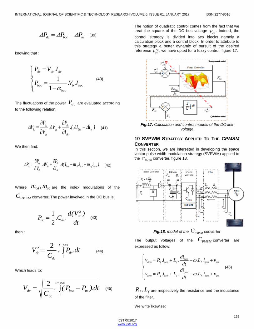
The notion of quadratic control comes from the fact that we treat the square of the DC bus voltage
dcV . Indeed, the
control strategy is divided into two blocks namely a calculation block and a control block. In order to attribute to this strategy a better dynamic of pursuit of the desired reference 2*
dcV , we have opted for a fuzzy control, figure 17.
Fig.17. Calculation and control models of the DC-link
voltage
10 SVPWM STRATEGY APPLIED TO THE CPMSM
CONVERTER In this section, we are interested in developing the space vector pulse width modulation strategy (SVPWM) applied to the
PMSMC converter, figure 18.
Fig.18. model of the PMSMC converter
The output voltages of the PMSMC converter are
expressed as follow:
qmdcmf
qcm
fqcmfqcm
dmqcmf
dcm
fdcmfdcm
vi.L.dt
di.Li.Rv
vi.L.dt
di.Li.Rv
(46)
ff LR , are respectively the resistance and the inductance
of the filter. We write likewise:

INTERNATIONAL JOURNAL OF SCIENTIFIC & TECHNOLOGY RESEARCH VOLUME 6, ISSUE 01, JANUARY 2017 ISSN 2277-8616
136 IJSTR©2017 www.ijstr.org
dccqqcm
dccddcm
V.mv
V.mv
(47)
Also :
)i,i(fI
i.mi.mI
qcmdcmcmm
qcmcqdcmcdm
(48)
Current fluctuations mI at the input of the PMSMC
converter are written as follows:
qcm
dc
qcm
dcm
dc
dcm
mi.
V
vi.
V
vI
(49)
Taking into account the Fortescue’s theory based on decomposition into a positive synchronous reference frame (PSRF) and a negative synchronous reference frame (NSRF), figure 19, We implement control loops of currents and voltages.
Fig.19.Positive and a negative synchronous references frame (PSRF, NSRF)
The current components ),( qcmdcm ii provided by the
converter PMSMC will be decomposed according to the
following model.
)2.θsin(.dcmn
i)2.θcos(.qcmn
iqcmp
iqcm
i
)2.θsin(.qcmn
i)2.θcos(.dcmn
idcmp
idcm
i
(50)
Where:
q
x,d
x(d, q)-axiscomponents in the PSRF frame,
qp
x,dp
x(d, q)-axiscomponents of the positive
sequence in the PSRF frame,
qn
x,dn
x(d, q)-axiscomponents of the negative
sequence in the NSRF frame,
Thus, the fluctuations of the components of the current supplied to the machine are given by:
)cos(...2)sin(..2
)cos(...2)sin(..2
2.θdcmni2.θ.
qcmni
t
qcmi
2.θqcmni2.θ.
dcmni
t
dcmi
(51)
The components of the reference voltage (** , qmdm vv )
applied to the terminals of the PMSM machine are evaluated in accordance with the following block diagram:
Fig.20. Voltage control loops at the terminals of the PMSM
machine
We define the variations of the deviationsdcmi ,
qcmi , and
dcV by the following relations:
dcdc
dcV
m
rrem
dcmnqcmn
i
qcmndcmn
i
VC
P
t
J
fTT
t
2.θi2.θ.it
2.θi2.θ.it
dc
qcm
dcm
.
.
)cos(...2)sin(..2
)cos(...2)sin(..2
(52)

INTERNATIONAL JOURNAL OF SCIENTIFIC & TECHNOLOGY RESEARCH VOLUME 6, ISSUE 01, JANUARY 2017 ISSN 2277-8616
137 IJSTR©2017 www.ijstr.org
The vectors dcmSf and
qcmSf generated by the fuzzy
controllers integrated in the (d, q) axis current control loops are defined as follows:
dt
di.Li.RSf
dt
di.Li.RSf
qcm
qqcmsqcm
dcm
ddcmsdcm
(53)
The references of the components *
dmv and *
qmv of the
voltage at the terminals of the PMSM machine being obtained and taking into account the existence of the (
ff LR , ) filter of the low-pass type,which completely
eliminates all frequencies above the cutoff frequency while passing those below unchanged. We then constitute the
components of the reference voltage *
dcv and *
qcv that the
converter must generate:
*
qm
*
dcf
*
qcf
*
qc
*
dm
*
qcf
*
dcf
*
dc
vi.L.i.Rv
vi.L.i.Rv
(54)
The components of the reference voltage *
dcv and *
qcv are
subsequently transferred to a fixed reference frame ( , )
in order to apply the SVPWM technique.
*
dqc
t..j*
cv.ev
(55)
From where:
)vi.L.i.R.(cos)vi.L.i.R.(sinv
)vi.L.i.R.(sin)vi.L.i.R.(cosv
*
qm
*
dcf
*
qcf
*
dm
*
qcf
*
dcf
*
c
*
qm
*
dcf
*
qcf
*
dm
*
qcf
*
dcf
*
c
(56)
It is then necessary to locate the sector of belonging of the
desired reference voltage vector*
cv which the PMSMC
converter must supply, figure 21.
Fig.21. SVPWM technic
With referring to Figure 21, we write:
)v(angle
)vi.L.i.R.(sin)vi.L.i.R.(cos
)vi.L.i.R.(cos)vi.L.i.R.(singtan
c
*
qm
*
dcf
*
qcf
*
dm
*
qcf
*
dcf
*
qm
*
dcf
*
qcf
*
dm
*
qcf
*
dcf
1
1
(57)
The distribution of the states of the keys 321 KKK as well as
their application timesT , over a modulation period HT are
illustrated in Figure 22.
Fig.22.Distribution of key control times
The keys 321 KKK application times in a sector i are
defined as follows:
]).i(sin[.T.
V
v.T
].isin[.T.V
v.T
H
dc
*
c
i
H
dc
*
c
i
312
32
1
(58)
Therefore, the average value of the voltage cv
supplied by the PMSMC converter is:
INTERNATIONAL JOURNAL OF SCIENTIFIC & TECHNOLOGY RESEARCH VOLUME 6, ISSUE 01, JANUARY 2017 ISSN 2277-8616
138 IJSTR©2017 www.ijstr.org
3
1
31
003
2
3
21
.j
dci
).i.(j
dcic
H
ce.V..Te.V..Tv.T.
Tv
(59)
Where :
4
1
0
iiHTTT
T
(60)
This voltage will be transferred to the (d, q) reference frame according to the following relation:
3
1
31
003
2
3
21
.j
dci
).i.(j
dcic
H
.j
dqce.V..Te.V..Tv.T.
T.ev
(61)
11 TECHNIQUE DE FILTRAGE In order to improve the quality of the energy exchanged between the
PMSMC converter and the PMSM machine, we
have integrated a low pass filter (ff LR , ). The filter cut-off
frequency (cf ) is given by:
f
f
cL..
Rf
2
(62)
By application of the Laplace transform, the currents at the
output of the ( ff LR , )filter are expressed as follows:
ff
dcmfqmqcm
qcm
ff
qcmfdmdcm
dcm
L.pR
I.L.VVI
L.pR
I.L.VVI
(63)
Numerically one writes:
Or :
e
c
qmdcmfqcm
f
qcm
ec
qcm
e
c
dmqcmfdcm
f
dcm
ec
dcm
Tf..
)n(V)n(I.L.)n(V.
L)n(I.
T.f..)n(I
Tf..
)n(V)n(I.L.)n(V.
L)n(I.
T.f..)n(I
12
11
12
1
12
11
12
1
(65)
Where eT is the sampling period.
12 PHASE LOCKED LOOP (PLL) The transformations of Park, by means of the use of the
matrix P , Of axes (d, q) that we have established, Were
based on arguments perfectly identical to those of the
systems of voltages (currents) studied, (icmic IV , ).The aim of
this approach was to reconstitute reference variables, assigned to the control loops, which were extremely precise, and on the other hand to aim at a perfect synchronization of the procedures for digital processing of the various state variables. On the basis that:
))t(varg(Psin(arg.V.v
))t(varg(Pcos(arg.V.v
icmaxcqc
icmaxcdc
2
3
2
3
(66)
In these circumstances, we must ensure that:
))(arg(arg tvP ic
(67)
It then follows:
))t(varg(P.(argV.vicmaxcqc
2
3
(68)
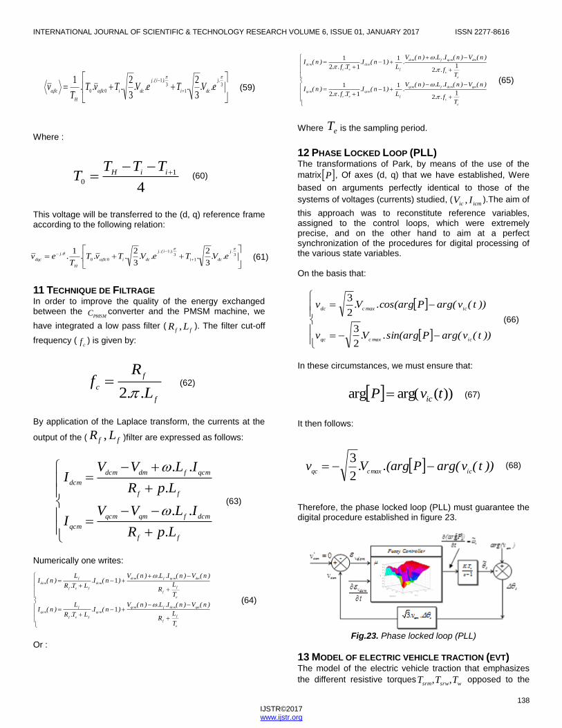
Therefore, the phase locked loop (PLL) must guarantee the digital procedure established in figure 23.
Fig.23. Phase locked loop (PLL)
13 MODEL OF ELECTRIC VEHICLE TRACTION (EVT) The model of the electric vehicle traction that emphasizes
the different resistive torqueswsrwsrm TTT ,, opposed to the
e
f
f
qmdcmfqcm
qcm
fef
f
qcm
e
f
f
dmqcmfdcm
dcm
fef
f
dcm
T
LR
)n(V)n(I.L.)n(V)n(I.
LT.R
L)n(I
T
LR
)n(V)n(I.L.)n(V)n(I.
LT.R
L)n(I
1
1
(64)
INTERNATIONAL JOURNAL OF SCIENTIFIC & TECHNOLOGY RESEARCH VOLUME 6, ISSUE 01, JANUARY 2017 ISSN 2277-8616
139 IJSTR©2017 www.ijstr.org
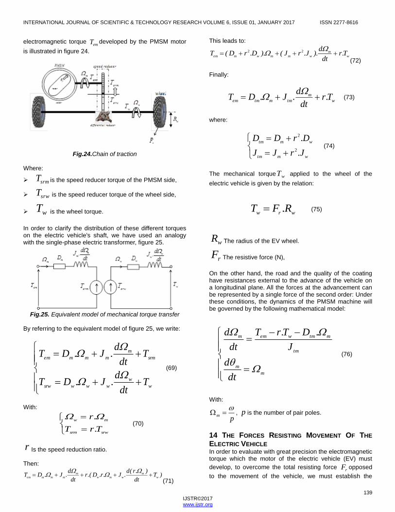
electromagnetic torque emT developed by the PMSM motor
is illustrated in figure 24.
Fig.24.Chain of traction
Where:
srmT is the speed reducer torque of the PMSM side,
srwT is the speed reducer torque of the wheel side,
wT is the wheel torque.
In order to clarify the distribution of these different torques on the electric vehicle's shaft, we have used an analogy with the single-phase electric transformer, figure 25.
Fig.25. Equivalent model of mechanical torque transfer
By referring to the equivalent model of figure 25, we write:
w
w
wwwsrw
srm
m
mmmem
Tdt
d.J.DT
Tdt
d.J.DT
(69)
With:
srwsrm
mw
T.rT
.r
(70)
r Is the speed reduction ratio. Then:
)Tdt
).r(d.J.r.D.(r
dt
d.J.DT
w
m
wmw
m
mmmem
(71)
This leads to:
w
m
wmmwmemT.r
dt
d).J.rJ().D.rD(T
22
(72) Finally:
w
m
tmmtmemT.r
dt
d.J.DT
(73)
where:
wmtm
wmtm
J.rJJ
D.rDD
2
2
(74)
The mechanical torque wT applied to the wheel of the
electric vehicle is given by the relation:
wrwR.FT
(75)
wR The radius of the EV wheel.
rF The resistive force (N),
On the other hand, the road and the quality of the coating have resistances external to the advance of the vehicle on a longitudinal plane. All the forces at the advancement can be represented by a single force of the second order: Under these conditions, the dynamics of the PMSM machine will be governed by the following mathematical model:
m
m
tm
mtmwemm
dt
d
J
.DT.rT
dt
d
(76)
With:
pm
, p is the number of pair poles.
14 THE FORCES RESISTING MOVEMENT OF THE
ELECTRIC VEHICLE In order to evaluate with great precision the electromagnetic torque which the motor of the electric vehicle (EV) must
develop, to overcome the total resisting force rF opposed
to the movement of the vehicle, we must establish the

INTERNATIONAL JOURNAL OF SCIENTIFIC & TECHNOLOGY RESEARCH VOLUME 6, ISSUE 01, JANUARY 2017 ISSN 2277-8616
140 IJSTR©2017 www.ijstr.org
balance of all the forces i
rir FF likely to act during the
movement of this vehicle. In effect, a moving vehicle is subjected overall to a force opposed to the penetration into
the airrapF , to a force of opposition to the rolling rrolF and
possibly to a force of opposition to the rise in a slope rstF .
14.1 Force of penetration into air
This force rapF is created by the mass of air that the vehicle
in motion wishes to pass through.
Fig.26. Effect of the force of penetration into the air
The force required to penetrate the air
rapF , it is calculated
by applying the relation:
2
2
1EVxEVrap
V.C.S..F
(77)
Where :
EV
The density of the vehicle,
S The surface taken to the wind,
xC
Coefficient of penetration into air,
EVV
Electric vehicle speed.
14.2 Rolling resistance force
This force rrolF is applied to the vehicle as a result of the
contact of these wheels with the road followed.
Fig.27. Effect of the rolling resistance force
The rolling resistance force rrolF calculated by applying
the relation:
)V.kk.(g.MFEVrrolrrolEVrrol
2
21
(78)
Where :
EVM The mass of the vehicle,
g The acceleration of gravity,
rrolrrol kk 21 , Coefficients of rolling resistance.
14.3 Slope force
This force rstF is created at times when the vehicle attacks
a slope. In fact, it depends on the weight of the vehicle EVP
and the angle of inclination of the road p used by the
vehicle.
Fig.28. Effect of the sloping terrain force
The force to be defeated on a sloping terrain rstF is
calculated by mean of the following relation:
)sin(.PFpEVrst
(79)
Where gMP EVEV . .
14.4Centrifugal Force In Newtonian mechanics centrifugal force Fc is a force of inertia directed outside the axis of rotation which seems to act on all objects when they are observed in a rotating reference frame. The concept of centrifugal force can be applied to vehicles in rotational motion according to a certain curvature.
Fig.29. Centrifugal force applied to anelectric vehicle

INTERNATIONAL JOURNAL OF SCIENTIFIC & TECHNOLOGY RESEARCH VOLUME 6, ISSUE 01, JANUARY 2017 ISSN 2277-8616
141 IJSTR©2017 www.ijstr.org
Its intensity is given by the formula:
c
EVEV
cR
V.MF
2
(80)
Rc Is the distance from the axis of rotation to the center of gravity of the electric vehicle (EV), i.e. the radius of curvature of the path in meters (m).This reaction force Fc is sometimes described as a centrifugal inertial reaction [37] [38] that is a force which is centrifuged, which is an equal and opposite reactive force to the centripetal force which is the curvature of the path.
Fig.30. Forces applied in a curved path to anelectric vehicle
By referring to the previous figure, we write:
g.R
V)(tg
c
EV
2
(81)
Thus, the total resultant force Fr applied to a moving vehicle in the different types of roads is given by the relation:
crstrrolraprFFFFF
(82)
Then:
c
EVEV
pVEVErrolrrolVEVExVErR
V.M)sin(.P)V.kk.(g.MV.C.S..F
2
2
21
2
2
1
(83)
Finally:
2
212
1VE
c
EV
rrolVExVEpVErrolVErV).
R
Mk.PC.S..()sin(.Pk.PF
(84)
This total resistive force can be expressed as follows:
)V.(F)(FFFVErprrr
2
210
(85)
Where:
2
2
2
2
1
10
2
1VE
c
EV
rrolVExVEVEr
pVEpr
rrolVEr
V).R
Mk.PC.S..()V.(F
)sin(.P)(F
k.PF
(86)
Therefore, we write the total resistant force opposed to the movement of the vehicle is three-dimensional:
)V,,P(fFVEpVEVEr
2
(87)
The dynamics of the electric vehicle brought on the motor shaft then becomes:
m
m
tm
mtmVEpVEVEwemm
dt
d
J
.D)V,,P(f.R.rT
dt
d
2
(88)
Then:
VE
w
m
tm
mtmVEpVEVEwemm
V.R.rdt
d
J
.D)V,,P(f.R.rT
dt
d
1
2
(89)
Taking into account the link between the linear speed of the
electric vehicle VEV and that of the wheels
w :
mw
wwVE
.r
.RV
(90)
We obtain:
2
2
222
22
1m
c
EV
rrolVExVEwmr).
R
Mk.PC.S...(R.r).(F
(91)
15 SIMULATIONS AND RESULTS We simulated the behavior of an electric vehicle with the following parameters:
3.3.1 mKgVE The density of the vehicle,
22.1 mS The surface taken to the wind,
29.0xC Coefficient of penetration into air,
VEV Electric vehicle speed.
KgMVE 1400 The mass of the vehicle,
2.81.9 smg The acceleration of gravity,

INTERNATIONAL JOURNAL OF SCIENTIFIC & TECHNOLOGY RESEARCH VOLUME 6, ISSUE 01, JANUARY 2017 ISSN 2277-8616
142 IJSTR©2017 www.ijstr.org
6
2
3
1 10.4,32,10.5,12 rrolrrol kk Coefficients of
rolling resistance.
92.0r the speed reduction ratio.
mRw 3.0 The radius of the EV wheel.
The parameters of the PMSM motor are:
stator resistance: 4578.0sR , d-axis inductance:
HLd 00334.0 , q-axis inductance: HLq 00334.0
,flux: weberf 171.0 ,inertia:2.01469.0 mKgJm ,
pair poles: 4p , nominal torque: mNTemn .20 ,
friction: mNDm .00334.0
We simulated the case
where from the instant st 2.1 up to st 5 the electric
vehicle attacks a slope of 030p .
Fig.31. rotational speed of the PMSM motor m
Fig.32. Time evolution of electric vehicle speed
Once the electric vehicle EV starts the rise of the slope, the
associated regulators act so that the rotational speed of the
PMSM motor m catches up to its reference value *
m in an
extremely short time. Therefore, the vehicle speed EVV
remains constant during the climb. This demonstrates the robustness of integrated fuzzy control loops.
Fig.33. Time evolution of the electromagnetique and
resistive torques
We simulated the case where from the instant st 2.1 up
to st 5 the electric vehicle attacks a slope of %8 .
Fig.34.Time evolution of m
During the rise in a slope the variations in the speed of the PMSM are similarly insignificant.
Fig.35.Torque evolution during the rise in a slope of %8
The electromagnetic torque Tem perfectly compensates for the resistive torque Tw resulting essentially from the sloping rise
p .

INTERNATIONAL JOURNAL OF SCIENTIFIC & TECHNOLOGY RESEARCH VOLUME 6, ISSUE 01, JANUARY 2017 ISSN 2277-8616
143 IJSTR©2017 www.ijstr.org
Fig.36. Time evolution of the DC link voltage dcV
The level of the DC bus voltage dcV remains insensitive to
the torque rise of the electric vehicle, which proves that the control strategies adopted have perfectly isolated the engine power system from any abrupt change in the EV
vehicle operator mode.
Fig.37. Time evolution of current
The q-axis component of the current qcmi supplied by the
converter PMSMC acts in a notable manner to compensate
for the resistive torque.This results from the fact that this
component is the most weighted qcmdm i. in the expression
of the electromagnetic torqueemT . We simulated the descent
of the electric vehicle with a negative slope of %8 .
Fig.38.Time evolution of m during a negative slope %8
We notice that when the vehicle picks up speed EVV at the
beginning of the descent, the regulators engage a braking strategy and we notice that the speed regains its reference value. On the other hand, we observe the engagement of a regenerative braking strategy because the torque becomes negative and the motor returns electrical energy to the battery.
Fig.39. Time evolution of emT and w
T during a negative
slope %8
Fig.40.Time evolution of dcmi and qcm
i during a negative
slope %8
Fig.41. Time evolution of
EVV during a negative slope %8
Similarly, during the descent into a ramp, the fuzzy control strategies act in such a way as to attenuate the excesses of certain state variables. We simulated the behavior of the electric vehicle the moment it takes a turn, that is to say when it is subjected to the centrifugal force
cF which pushes
it towards the outside of the curve.

INTERNATIONAL JOURNAL OF SCIENTIFIC & TECHNOLOGY RESEARCH VOLUME 6, ISSUE 01, JANUARY 2017 ISSN 2277-8616
144 IJSTR©2017 www.ijstr.org
Fig.42. Time evolution of
EVV during a curved path with a
curvative radius mRc
100
Figure.43.Time evolution of EVV during a curved path with
a curvative radius mRc
10
During the turning, the control strategies fuzz act to reduce the excess speed and this by an evaluation of new references ensuring an extreme degree of safety.
16 CONCLUSION In this work, we are interested in the implementation of intelligent strategies based on fuzzy controllers to ensure optimal operation of an electric vehicle.we can say that the design and optimization of the traction chain of an electric vehicle is a multidisciplinary problem that must take into consideration, at a minimum, batteries, mechanical transmission and electromagnetic powered electronics. The search for a minimal cost is added to the scientific and technological difficulties. The future electric vehicle must be able, with appropriate control, to use the energy stored in the batteries in order to sustain the electricity network during periods of peak consumption or in case of emergency (shutdown of a production plant) . The energy stored in the battery of the vehicle could also supply the electrical requirements of the dwelling. This technology requires that the charger embedded in the vehicle as well as the interface between the vehicle and the electrical network are bidirectional. The results obtained are extremely encouraging and prove that the more we refine the electromagnetic model of the electric vehicle the more we obtain a favorable ground for a better implementation of the strategies of control especially the fuzzy strategies.
REFERENCES [1] CONTROL SYSTEMS FOR HIGH PERFORMANCE
ELECTRIC CARS PEDRET Paula, WEBB Jonathan, , BAYONA
Guillermo, MOURE Christophe, BOLTSHAUSER Sandro Volume 6 - Issue 1 - Pages 88-94.
[2] DESIGN CONSIDERATIONS FOR FAST AC BATTERY CHARGERS BERTOLUZZO Manuele, BUJA Giuseppe, PEDE GIOVANNI Volume 6 - Issue 1 - Pages 147-154, World Electric Vehicle Journal Vol. 6 - ISSN 2032-6653 - © 2013 WEVA.
[3] M. ISMAIL, M. Mustafa HASSAN “Load Frequency Control Adaptation Using Artificial Intelligent Techniques for One and Two Different Areas Power System” International Journal of Control, Automation and Systems IJCAS, Vol. 1, NO. 1, january 2012, p12-p23.
[4] A. M.A.Haidar,A. Mohamed and A. Hussain,”Vulnerability control of large scale interconnected power system using neuro-fuzzy load shedding approach”,Expert Systems With Applicatons, Elsevier 37.pp. 3171-3176, 2010.
[5] MOTOR-GENERATOR CONTROL TO IMPROVE SHIFT QUALITY FOR A DUAL MODE POWER SPLIT TRANSMISSION HONG Sungwha, CHOI Woulsun, AHN Sunghyun, LEE Geontae, SON Hanho, KIM Yongjoo, KIM Hyunsoo Volume 6 - Issue 2 - Pages 245-250, World Electric Vehicle Journal Vol. 6 - ISSN 2032-6653 - © 2013 WEVA .
[6] Alireza Alfi, "Hybrid state-feedback sliding-mode controller design using fuzzy logic for four-wheel-steering vehicles ", Vehicle System Dynamics, vol. 47, Issue. 3, pp. 265-284, 2009.
[7] Alireza Alfi, "Swarm optimization tuned Mamdani fuzzy controller for diabetes delayed model ", Turkish Journal of Electrical Engineering and Computer Sciences, vol. 21, pp. 2110-2126, 2013.
[8] Alireza Alfi, "Optimal design of type-2 fuzzy controller using particle swarm optimization for HVAC systems", Automatika-Journal for Control, Measurement, Electronics, Computing and Communications, vol. 55, vol. 1, pp. 69-78, 2014.
[9] D. Nazari, M. Abadi, M. H. Khooban, A. Alfi, M. Siahi "Design of optimal self-regulation Mamdani-type fuzzy inference controller for type 1 diabetes mellitus", Arabian Journal for Science and Engineering, vol. 39, pp. 977-986, 2014.
[10] M. H. Khooban, A. Alfi and Abadi, "Control of a class of nonlinear uncertain chaotic systems via an optimal type-2 fuzzy PID controller", IET Science, Measurement & Tecnology, vol. 7, no. 1, pp. 50-58, 2013.

INTERNATIONAL JOURNAL OF SCIENTIFIC & TECHNOLOGY RESEARCH VOLUME 6, ISSUE 01, JANUARY 2017 ISSN 2277-8616
145 IJSTR©2017 www.ijstr.org
[11] M. Hassan Khooban, Alireza Alfi, Davood Nazari and Maryam Abadi, "Teaching learning based optimal interval type-2 fuzzy PID controller design: A nonholonomic wheeled mobile robots", Robotica, vol. 31, no. 7, pp. 1059-1071, 2013.
[12] A. Alfi, A. Akbarzadeh Kalat and M. Hassan Khooban , “Adaptive fuzzy sliding mode control for synchronization of uncertain non-identical chaotic systems using bacterial foraging optimization” Journal of Intelligent & Fuzzy Systems 26(2014) 2567-2576, DOI: 10.3233/IFS-130928 IOS Press.
[13] Oscar Castillo, Patricia Melin, Jausz Kacprzyk, Wiltold Pedrycz,” Type 2 Fuzzy Logic : Theory and Applications”, IEEE International Conference on Granular Computing, 2007.
[14] IMPACT OF ELECTROMOBILITY ON AUTOMOTIVE ARCHITECTURES LUCCARELLI Martin, RUSSO SPENA Pasquale, MATT Dominik Volume 6 - Issue 1 - Pages 1-8, World Electric Vehicle Journal Vol. 6 - ISSN 2032-6653 - © 2013 WEVA .
[15] H. Jouini, K. Jemaï, and S. Chebbi,”Voltage Stability Control of Electrical Network using Intelligent Load Shedding Strategy based on Fuzzy Logic”, Hindawi Publishing Corporation, Mathematical Problems in Engineering, Volume 2010, Article ID 341257, 17 pages.
[16] K. Jemaï, ” New Fuzzy Approach for Modeling Random Disturbances”, Journal of Control Science and Engineering, Volume 2, Number 1, P 16-27, February 2014 (Serial Number 2).
[17] A. Ouederni, K. Jemaï, H. Trabelsi, "Modelling and Control of a PMSG-Based Variable Speed Wind Turbine under Unbalanced Conditions", International Journal of Research and Reviews in Electrical and Computer Engineering (IJRRECE), Vol. 2, No. 1, March 2012, ISSN: 2046-5149.
[18] IMPLEMENTING ELECTRIC VEHICLES IN URBAN
DISTRIBUTION: A DISCRETE EVENT SIMULATION LEBEAU Philippe, MACHARIS Cathy, VAN MIERLO Joeri, MAES Guillaume Volume 6 - Issue 1 - Pages 38-47, World Electric Vehicle Journal Vol. 6 - ISSN 2032-6653 - © 2013 WEVA.