international journal of mining science and technology · 2018-12-18 · flotation column reactors...
TRANSCRIPT

International Journal of Mining Science and Technology xxx (2018) xxx–xxx
Contents lists available at ScienceDirect
International Journal of Mining Science and Technology
journal homepage: www.elsevier .com/locate / i jmst
CFD model simulation of bubble surface area flux in flotation columnreactor in presence of minerals
https://doi.org/10.1016/j.ijmst.2018.05.0042095-2686/� 2018 Published by Elsevier B.V. on behalf of China University of Mining & Technology.This is an open access article under the CC BY-NC-ND license (http://creativecommons.org/licenses/by-nc-nd/4.0/).
⇑ Corresponding author.E-mail address: [email protected] (J. Naser).
Please cite this article in press as: Sarhan AR et al. CFD model simulation of bubble surface area flux in flotation column reactor in presence of mineJ Min Sci Technol (2018), https://doi.org/10.1016/j.ijmst.2018.05.004
A.R. Sarhan a,b, J. Naser a,⇑, G. Brooks a
aDepartment of Mechanical and Product Design Engineering, Swinburne University of Technology, Hawthorn, Victoria 3122, AustraliabDepartment of Mechanical Engineering University of Anbar, Ramadi, Anbar 31001, Iraq
a r t i c l e i n f o
Article history:Received 11 April 2017Received in revised form 1 February 2018Accepted 15 May 2018Available online xxxx
Keywords:CFDFroth flotationBubble surface area fluxSolid propertiesBubble concentration
a b s t r a c t
Bubble surface area flux (Sb) is one of the main design parameter in flotation column that typicallyemployed to describe the gas dispersion properties, and it has a strong correlation with the flotation rateconstant. There is a limited information available in the literature regarding the effect of particle type,density, wettability and concentration on Sb. In this paper, computational fluid dynamics (CFD) simula-tions are performed to study the gas–liquid–solid three-phase flow dynamics in flotation column byemploying the Eulerian–Eulerian formulation with k-e turbulence model. The model is developed bywriting Fortran subroutine and incorporating then into the commercial CFD code AVL FIRE, v.2014.This paper studies the effects of superficial gas velocities and particle type, density, wettability and con-centration on Sb and bubble concentration in the flotation column. The model has been validated againstpublished experimental data. It was found that the CFD model was able to predict, where the responsevariable as indicated by R-Square value of 0.98. These results suggest that the developed CFD model isreasonable to describe the flotation column reactor. From the CFD results, it is also found that Sbdecreased with increasing solid concentration and hydrophobicity, but increased with increasing super-ficial gas velocity. For example, approximately 28% reduction in the surface area flux is observed whencoal concentration is increased from 0 to 10%, by volume. While for the same solid concentration andgas flow rate, the bubble surface area flux is approximately increased by 7% in the presences of sphalerite.A possible explanation for this might be that increasing solid concentration and hydrophobicity promotesthe bubble coalescence rate leading to the increase in bubble size. Also, it was found that the bubble con-centration would decrease with addition of hydrophobic particle (i.e., coal). For instance, under the sameoperating conditions, approximately 23% reduction in the bubble concentration is predicted when thesystem was working with hydrophobic particles. The results presented are useful for understanding flowdynamics of three-phase system and provide a basis for further development of CFD model for flotationcolumn.� 2018 Published by Elsevier B.V. on behalf of China University of Mining & Technology. This is an open
access article under the CC BY-NC-ND license (http://creativecommons.org/licenses/by-nc-nd/4.0/).
1. Introduction
Flotation column reactors (FCRs) are extensively used in indus-try for separating valuable minerals from a mixture with gangueminerals. They are utilized in petrochemical refining, water treat-ment, mineral processing, and deinking of recycled paper, andmany other applications [1–7]. This is due to their ability to treatcomplex and low grade ores where the mineral particle size istoo small for other separation techniques to be efficient [8]. Oneof the most significant applications of FCRs is their utilization inthe process of purification. FCRs offer many advantages over the
conventional mechanical flotation machine, including simpler con-trol procedure, lower operating and maintenance cost due to lackof moving parts and improved metallurgical performance. Basi-cally, gas bubbles are injected into pulp zone which contains oneor more suspended solids to be removed. Only hydrophobic parti-cles have the opportunity to attach to the gas bubbles and com-mence their journey to a froth layer where they are collected asa concentrate. The hydrophilic particles are left behind in the pulpzone and finally removed from a FCR as tailing [9–11].
The performance of a FCR depends on a number of interrelatedvariables. Operation variables, such as feed rate, slurry concentra-tion, particle size and gas flow rate, are considered to be the mostimportant parameters that can influence the flotation cellhydrodynamics [11–13]. Gas dispersion shows how the gas phase
rals. Int

2 A.R. Sarhan et al. / International Journal of Mining Science and Technology xxx (2018) xxx–xxx
is distributed within a FCR. Gas holdup (eg), superficial gas velocity(Jg), bubble size (db) and bubble surface area flux (Sb) are the mainparameters that typically used to describe the gas dispersion.Therefore, the ability to accurately predict the effect of operatingparameters that control the flow behavior in the FCRs is importantfor its design. The gas holdup is defined as the fraction occupied bythe gas bubble in the total volume of the mixture (gas, liquid, andsolids) in a FCR, commonly expressed as a percentage. Finch andDobby stated that gas holdup mainly depends on bubble size, gasand feed flow rate, liquid properties, solids concentrations, andthe size and density of particles [14]. The gas holdup (eg), superfi-cial gas rate (Jg), mean bubble diameter (d32) and bubble surfacearea flux (Sb) are defined in the present study by Sarhan [7,15,16].
eg ¼ Hg � HHg
ð1Þ
Jg ¼Qg
Acð2Þ
d32 ¼PN
i¼1nid3iPN
i¼1nid2i
ð3Þ
Sb ¼6Jgd32
ð4Þ
where Hg, Qg and Ac are the height of the liquid after aeration, vol-umetric gas flow rate and the column cross-sectional area, respec-tively. Many attempts have been made by different researchgroups to relate these parameters to flotation performance[17–21]. For example, Jameson, Nam and Young proposed a funda-mental relationship for the first-order flotation rate constant (kc) asa function of superficial gas velocity, mean bubble diameter and thecollection efficiency (Ek) [21].
kc ¼3EkJg2d32
ð5Þ
The previous relationship has been successfully validated byexperimental testing at the laboratory and plant scale [22,23].From Eqs. (4) and (3), the flotation rate constant can be expressedin terms of Sb as follows: kc = 0.25EkSb.
In the last few decades, a considerable number of studies onmeasurement of bubble surface area flux in a FCR have beenreported: includes studies by Bhunia et al. [9,16,22,24,25]. Gorain,Franzidis and Manlapig conducted an experimental investigationto determine the effect of gas dispersion properties on the flotationrate constant in plant and pilot scale mechanical flotation cellsover a range of operating conditions [22]. They concluded thatthe flotation rate constant was directly related to bubble surfacearea flux. Finch, Xiao, Hardie and Gomez discovered a linear rela-tionship between bubble surface area flux and the gas holdup fora wide range of cell types and operating regimes [16]. As a result,they suggested the following equation Sb = 5.5eg to replace bubblesurface area flux by gas holdup in the flotation performance eval-uation. Leiva, Vinnett, Contreras and Yianatos using a pilot-scaleflotation column showed that for the same value of Jg, a greatersensitivity in Sb estimation at lower values of d32 [24]. Bhunia,Kundu and Mukherjee claimed that bubble surface area flux exhi-bits a linear relationship with superficial gas velocity and frotherconcentration [9].
Gas dispersion characterization enhances the understanding ofits relationship with the metallurgical performance and allowscontrol strategies to be developed in FCRs. Thus, the ability to accu-rately predict gas dispersion in FCRs by using predicted bubblesize, superficial gas velocity and gas holdup is important fordesigning optimum industrial scale FRC. It should be mentioned
Please cite this article in press as: Sarhan AR et al. CFD model simulation of bubJ Min Sci Technol (2018), https://doi.org/10.1016/j.ijmst.2018.05.004
that the effect of solid’s hydrophobicity on bubble surface area fluxin FCRs is not yet investigated or not reported in open literature.Therefore, the objective of the present study is to predict the effectof process variables, namely, superficial gas velocity, solid particleconcentration and type on the bubble surface area flux in a FCR.The effect of slurry concentration and physical properties of solidparticle (hydrophobicity, type) on the number density of differentbubble sizes have also been investigated. In the present model,three-dimensional flow of a flotation column similar to the exper-imental model of Bhunia, Kundu and Mukherjee is simulated, andthen the model is used for further analysis [2].
2. Model development
2.1. Approaches to multiphase flow modeling
The term ‘‘multiphase flow” is referred to any fluid flow consist-ing of more than one phase or fluid type. Physical phases used inthe present study are gas, liquid and solid; however, in multiphaseflow, a phase can be described as an identifiable class of materialthat has a particular inertial response to and interaction with theflow and the potential field in which it is immersed [26]. The com-putational fluid dynamics (CFD) has provided the basis for furtherinsight into the hydrodynamics of multiphase flows. There are twoapproaches that can be used for the numerical calculation ofmultiphase flows, namely the Euler–Lagrange method and theEuler–Euler method. In the Euler-Lagrange method, liquid phaseis treated as a continuum by solving the time-averaged Navier-Stokes equations, whereas the dispersed phase is solved by trackinga large number of particles, bubbles, or droplets through the calcu-lated flow field. The liquid phase can exchange momentum, mass,and energy with the dispersed phase. The Euler-Euler method isbased on the concept of interpenetrating continua where the con-cept of phasic volume fraction is introduced as the volume of aphase that cannot be occupied by the other phases. In this method,volume fractions of continuous and dispersed phases are assumedto be continuous functions of space and time and their sum is equalto one. Therefore, from a computational perspective, the Euler–Euler method is more comprehensive and more accurate to use.In the current study, the Euler–Euler approach is used.
2.2. Volume fraction equation
Air–water–solid FCR can be described by three phases: liquidcontinuous (primary) phase and the dispersed (secondary) gasand solids phases. The volumes of gas phase Vg, liquid phase Vl
and solid phase Vs are respectively defined by [26].
Vg ¼ZagdV ; Vl ¼
ZaldV and Vs ¼
ZasdV ð6Þ
where ag, al and as are the gas, liquid and solid phases volume frac-tions (phase holdups) respectively. The compatibility conditionmust be observed: ag + al + as = 1.
2.3. Conservation equations
The governing equations used in the present model has beendescribed previously by Sarhan, Naser and Brooks [7]. For brevity,a brief description of the governing equations that were used in theCFD model will be introduced in this section. The flow in the air–water–solid FCR is incompressible and Newtonian. The conserva-tion of mass and momentum equations for each of the individualphases are derived by ensemble averaging of the local instanta-neous balances for each of these phases. Also, the interfacial massand momentum exchange between phases are included. In
ble surface area flux in flotation column reactor in presence of minerals. Int

A.R. Sarhan et al. / International Journal of Mining Science and Technology xxx (2018) xxx–xxx 3
Cartesian coordinates (x, y, z), the conservation equations in FCRare written as:
Continuity equation [7]:
@ðaqÞg@t
þr � ðaq u!Þg ¼ Cgs ð7Þ
@ðaqÞl@t
þr � ðaq u!Þl ¼ 0 ð8Þ
@ðaqÞs@t
þr � ðaq u!Þs ¼ �Cgs ð9Þ
where q and u! are the phase density and ensemble averaged veloc-ity, respectively. Last term on RHS of Eqs. (7) and (9) accounts forinter-phase mass transfer and is described through Eq. (19). Sub-scripts g, l and s represent the gas, liquid and solid phases,respectively.
Momentum equations [7]:
@ðaiqi u!
iÞ@t
þr � ðaiqi u!
i u!
iÞ ¼ �airpi þr � aiðsi þ Tti Þ þ aiqif
þ u!i
XNj¼1;j–i
Cij þXN
j¼1;j–i
Mij; i ¼ 1; . . . ;N
ð10Þwhere f is the body force vector which comprises of gravity g; and pi
the pressure which is assumed to identical for all phases (i.e., p = pi,i = 1, . . ., N). Last term on RHS of Eq. (10) accounts for the momen-tum interfacial exchange between phases (i = gas, liquid and solid)and is described through Eq. (14). Shear stress for each phase iswritten as:
si ¼ leff ;i ðr u!i þr u!Ti Þ �
23r: u!i
� �ð11Þ
where leff ;i is the effective viscosity for each phase. The effectiveviscosity of the solid phase is defined as [27].
leff ;s ¼ 0:8e2sqsdsgoð1þ eÞffiffiffiffiffiffiHs
p
r
þ 10qsdsffiffiffiffiffiffiffiffiffiffipHs
p
96ð1þ eÞesgo½1þ 0:8esgoð1þ eÞ�2 ð12Þ
where the granular temperature is defined as: Hs ¼ 0:334 u!s u!
s,and the radial distribution function is equal to
go ¼ 1= 1� ðes=es;maxÞ0:334h i
. Reynolds stress is determined using
the following equation.
Tti ¼ lt
i ðrv i þrvTi Þ �
23r � v iI
� �� 23qiKiI ð13Þ
where the turbulent viscosity of phase i is equal to lti ¼ ClqiðK2
i =eiÞ.The inter-phase momentum exchange term by considering the dragforce is given as [26].
Mp ¼ CD18qpA
000i jVrjVr ¼ �Mq ð14Þ
where CD, qp, A000i , and Vr are the drag coefficient, density of primary
phase (p), the interfacial area density, and the relative velocityVr ¼ Vq � Vp, respectively. For bubble flows where the bubble diam-eter is greater than 1 mm, [28] proposed an equation to calculatethe drag coefficient CD;
CD ¼ max min24Reb
ð1þ 0:15Re0:687b Þ; 72Reb
� �� �;
8Eo3ðEoþ 4Þ
� �ð15Þ
where Bubble Eötvös number Eo ¼ gðql � qgÞd232rl and the Reynolds
number Reb ¼ ðVrd32=v lÞ [7,28].
Please cite this article in press as: Sarhan AR et al. CFD model simulation of bubJ Min Sci Technol (2018), https://doi.org/10.1016/j.ijmst.2018.05.004
2.4. Description of population balance equation (PBE)
2.4.1. Bubble-bubble interaction modelTen different sizes of bubbles were chosen. The volume of the
upper bubble size was equal to twice the size of the lower bubblesize vn ¼ 2vn�1. The diameters of the bubble, which were trackedin this simulation, were varied between 0.5 and 4.0 mm. It wasassumed that the bubble of the lowest size entered the calculationdomain through the inlet at the bottom of the column. In order topredict the concentration number of different bubble classes, thepopulation balance equation (PBE) was employed in the presentmodel. Population balance equation was introduced as scalartransport equation in AVL-Fire. The scalar transport equation wasused to calculate the volume fraction of each bubble size. The pop-ulation balance equation is given as follows [29].
@
@tðagqg/iÞþr�agqgvg/i ¼r�agqgDgir/iþqgðBBi �DBi þBCi
�DCiÞ
ð16Þwhere BB and BC are the birth rates due to breakage and coales-cence; and DB and DC the death rates due to breakage and coales-cence, respectively. It should be noted that the density of gasphase is defined in the present model as qg ¼ ðqatt p þ 1:225Þ. Theattached particle density qatt p is given as
qatt p ¼np2qsd
3sp þ ntbqgd
332
np2d3sp þ ntbd
332
� 1:225 ð17Þ
where np2 is the number density of attached particles; ntb the num-ber density of bubbles; d32 the Sauter mean diameter of bubbles;and dsp the diameter of solids particles, respectively.
2.4.2. Bubble-particle interaction modelFor modeling flotation kinetic, the influence of attached parti-
cles in the kinetic equation was taken into account in the presentmodel by applying the source term of attachment and detachmentprocesses in the population balance equation as follows [30].
@ðaini/iÞ@t
þr � ðaini/i u!
iÞ ¼ �ua þud ð18Þ
where ua and ud are the source term of attachment and the sourceterm of detachment, respectively. The inter-phase mass transferbetween gas bubbles and solid particles is given by:
Cgs ¼�k1np1ntbð1� bÞ þ k2ntbb
qgagvsp
dtð19Þ
where k1 and k2 are the kinetic constants of attachment and detach-ment processes; np1 the number concentrations of free particles;and b the loading parameter, respectively. Loading parameter takesvalues which are positive real numbers. If b is equal to zero, thebubbles are free of particles and particles can easily attach. If b isequal to one, the attached particles only occupy about half of thetotal bubble surfaces and bubbles are fully loaded and no extra par-ticles can attach. In the present model, the bubble loading parame-ter b can be obtained from [31].
b ¼ np2
2ðd32=dspÞ2ntb
ð20Þ
2.5. Modeling of turbulence
The standard k-e approach that was proposed by Launder andSpalding in 1974 is widely used in the CFD simulations of hydrody-namics and heat transfer because of its feasible accuracy and itsavailability in most CFD codes [32,33]. It comprises three turbu-lence sub models: the mixture turbulence model, the dispersed
ble surface area flux in flotation column reactor in presence of minerals. Int
4 A.R. Sarhan et al. / International Journal of Mining Science and Technology xxx (2018) xxx–xxx
turbulence model, and a per-phase turbulence model [27]. Themixture turbulence model assumes the computational domain asa mixture and solves for k and e values which are common for allphases. This approach can be only used when the densities ofphases are comparable. Since there is a huge difference in the den-sity of dispersed and continuous phases, the mixture turbulencemodel cannot be used in this work. Since the computational effortsneeded for the dispersed turbulence model are less than those arerequired for the per-phase turbulence model, the k-e dispersed tur-bulence model is used in this investigation. In the dispersed turbu-lence approach, the modified k-e equations are solved for thecontinuous phase and the turbulence quantities of dispersed phaseare calculated using Tchen-theory correlations. The fluctuation dueto turbulence was also taken into account by solving for the inter-phase turbulent momentum transfer. The transport equation forthe turbulent kinetic energy k equals.
@ðaiqikiÞ@t
þrðaiqi u!
ikiÞ ¼ r � ai li þlt
i
rk
� �rki þ aiPi � aiqiei
þXN
j¼1;j–i
Kij þ kiXN
j¼1;j–i
Cij; i ¼ 1; . . . ;N
ð21Þ
where the production term due to shear for phase i is equal toPi ¼ Tt
i : r u!i. The dissipation rate of energy from the turbulent flowcomputes as
@ðaiqikiÞ@t
þrðaiqi u!
ikiÞ ¼ r � ai li þlt
i
rs
� �rei þ
XNj¼1;j–1
Dij
þ eiXN
j¼1;j–1
Cij þ aiC1Pieiki� aiC2Pi
e2iki
þ aiC4qieir � u!i; i ¼ 1; . . . ;N ð22ÞThe standard values of all empirical constants in the k–e turbu-
lence model are C1 ¼ 1:44; C2 ¼ 1:92; C4 ¼ �0:373; rk ¼ 1:0;re ¼ 1:3; and Cl ¼ 0:09.
Table 1Summary of the model formulation.
General Linear solver type
Pressure formulationRun modeGravitational body forceConvergence criteriaInlet conditionOutlet conditionMesh type
Models Eulerian–Eulerian flow approachDrag modelViscous-standard k–e, dispersed
Control Number of phases = 3Continuous phase = liquid phaseSecondary phase = gas, solidMinimum volume fraction
Materials Gas = airLiquid = waterSolid = coal, hydrophobicSolid = sphalerite, hydrophilic
Solver control Discretization
Equation control
Differencing scheme
No. of iterations 5
Please cite this article in press as: Sarhan AR et al. CFD model simulation of bubJ Min Sci Technol (2018), https://doi.org/10.1016/j.ijmst.2018.05.004
2.6. Solution domain description and AVL FIRE v.2014 setup
In the present model, three-dimensional flow of a flotation col-umn similar to the experimental model of Bhunia, Kundu andMukherjee has been simulated with AVL Fire version 2014 soft-ware [2]. The simulations were performed in an unsteady stateon Intel Xeon Quad Core Z420 Machine with processor speed3.60 GHz. The flotation column is 1.66 m high and 0.1 m in diam-eter. Two different cell sizes with increasing number of elements(50,343 and 154,787) were constructed to ensure mesh indepen-dency of obtained results. In order to evaluate the impact of thegrid on the results, simulations were carried out on both gridsusing a gas flow rate of 0.642, 1.072 and 1.485 cm/s and coal con-centration of 10%. It has been verified that the percentage ofchange of the solution in both cases is small. It was found thatthere were no significant differences in the results. Therefore,the mesh consisting 50,343 numerical meshes was chosen for fur-ther simulations. Summary of the model formulation is given inTable 1.
2.7. Intial and boundary conditions
Boundary conditions of the models are important for numericalcomputation. In this study, the boundary conditions are an inlet,outlet, and wall boundary conditions. The gas velocity at the inletis computed based on superficial gas velocity. Since the volumefraction of the gas is equal to 1, the inlet gas velocity is defined as.
uginlet ¼JgAC
agAinletð23Þ
where uginlet and Jg are the gas inlet velocity and the superficial gasvelocity, respectively; ag the volume fraction of gas at the inlet;and AC and Ainlet the cross-sectional area of the column and the totalcross-sectional area of the sparger, respectively. The pressureboundary condition is applied at the column outlet since it givesbetter convergence results [34]. In all cases, pressure is specifiedto atmospheric pressure at the column outlet. At the wall boundary,
GSTB
SIMPLEUnsteady, Dt = 0.01 sFull body force–Y direction0.0001Normal velocityStatic pressure, 100000 Pa50,343 grids, symmetric grid
Tomiyama2004 for gas bubbles Schiller–Neumann for particles
Gas, liquid, and solid
1E-006
Calculation of boundary values ExtrapolateCalculation of derivative Least sq. fitCompressibility IncompressibleWall treatment Hybrid wall treatmentMomentum First order UDSContinuity First order CDSTurbulence First order UDSEnergy First order UDSScalar First order UDSVolume fraction First order UDS
ble surface area flux in flotation column reactor in presence of minerals. Int
A.R. Sarhan et al. / International Journal of Mining Science and Technology xxx (2018) xxx–xxx 5
free slip boundary conditions are used for gas bubbles, liquid andparticles, respectively.
Gas bubbles were introduced at the bottom of the column. Thesuperficial gas velocity was varied between 0.64 to 2.76 cm/s. Thisspecific geometry was used to validate CFD results in flotation col-umn by comparing simulated gas holdup profiles with the experi-mental data in an identical setup. The detail of the boundary andinitial conditions for flotation column as used in Bhunia, Kunduand Mukherjee is presented in Table 2 [2].
3. Results and discussion
3.1. Model validation
Use of computational fluid dynamics (CFD) methodology makesit possible to numerically solve mass and momentum conservationequations in complicated multiphase systems. However, it isalways necessary to verify whether the simulated results are valid.Therefore, laboratory scale experimental data studied by Bhunia,Kundu and Mukherjee were used to validate the present CFD pre-dictions for the selected set of conditions, then the model is usedfor further analysis [2].
As part of the code validation, simulations were carried out fords = 64 mm at Jg = 0.64–2.75 cm/s and Cs = 0 to 15%, by volume. Twotypes of solid were used in the present work, sphalerite and coal ashydrophilic and hydrophobic particles, respectively. The density ofsphalerite and coal were 3160 and 1600 kg/m3, respectively.
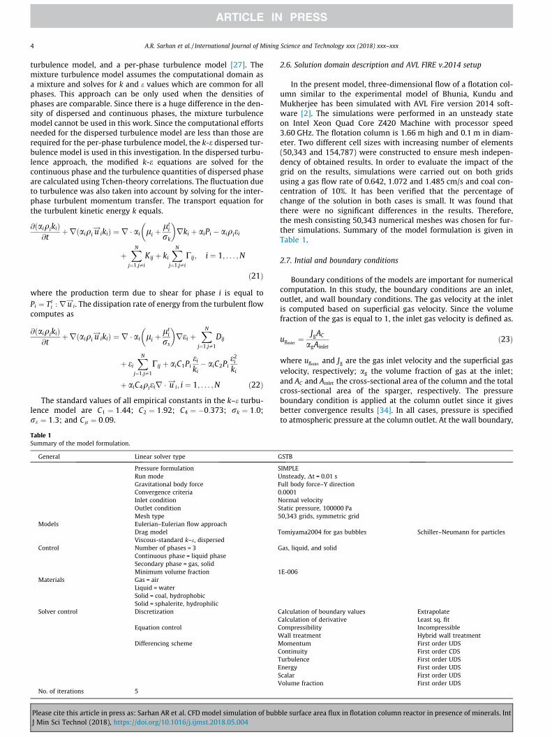
The residual analysis for eg values have been plotted in Fig. 1.Fig. 1a shows the predicted values versus the actual values plot.This plot shows that the CFD model was able to accurately predictthe gas holdup inside the FCR as indicated by R-Square (R2) value of0.98, adjust R-Square (R2
adj) of 0.96 and residual sum of squares(RSS) of 0.0029. Fig. 1b represents the residual plot. Fig. 1b showsthat the points are falling randomly on the both sides of zero, sug-gesting that there are no unusual points that have influence on thepredicted results during the simulation. This random pattern alsoindicates that a linear model provides a decent fit to the data. Todiscover and show, the underlying frequency distribution of pre-dicted results, the histogram graph is used (Fig. 1c). Fig. 1c showsthat the predicted data are symmetric which means the average isa good approximation for the center of the predicted data. There-fore, the predicted values are well fitted with the actual values.Fig. 1d demonstrates that the residuals show a linear pattern,which means the predicted values are well fitted with the actualvalues. These results suggest that the developed CFD model is rea-sonable for simulating FCR.
Table 2Operation conditions used in the present simulation.
Item Value
Column dimensions 0.1 mColumn diameter 1.66 mColumn height 1.3 mInitial liquid height, Ho qg = 1.1 kg/m3; mg = 0.00001 Pa sOperation Parameters ql = 1000 kg/m3; ml = 0.001 Pa sGas phase Coal particles, qs = 1600 kg/m3
Liquid phase Sphalerite particles, qs = 3160 kg/m3
Solid phase 20 �CAtmospheric pressure
Temperature Jg = 0.64, 1.07, 1.49, 1.91, 2.33, 2.76 cm/sPressure 0, 10, 15 vol.%Superficial gas velocity 64 mmSolid concentrationParticle size
Please cite this article in press as: Sarhan AR et al. CFD model simulation of bubJ Min Sci Technol (2018), https://doi.org/10.1016/j.ijmst.2018.05.004
3.2. Effect of slurry concentration and gas velocity on eg
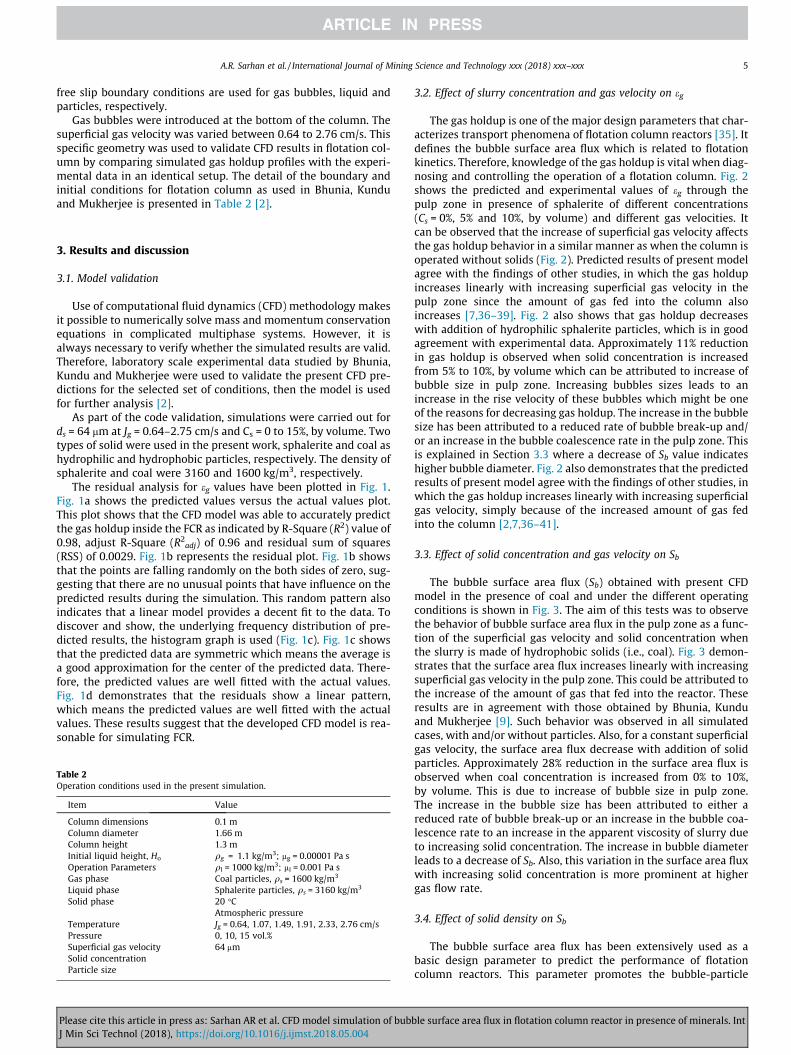
The gas holdup is one of the major design parameters that char-acterizes transport phenomena of flotation column reactors [35]. Itdefines the bubble surface area flux which is related to flotationkinetics. Therefore, knowledge of the gas holdup is vital when diag-nosing and controlling the operation of a flotation column. Fig. 2shows the predicted and experimental values of eg through thepulp zone in presence of sphalerite of different concentrations(Cs = 0%, 5% and 10%, by volume) and different gas velocities. Itcan be observed that the increase of superficial gas velocity affectsthe gas holdup behavior in a similar manner as when the column isoperated without solids (Fig. 2). Predicted results of present modelagree with the findings of other studies, in which the gas holdupincreases linearly with increasing superficial gas velocity in thepulp zone since the amount of gas fed into the column alsoincreases [7,36–39]. Fig. 2 also shows that gas holdup decreaseswith addition of hydrophilic sphalerite particles, which is in goodagreement with experimental data. Approximately 11% reductionin gas holdup is observed when solid concentration is increasedfrom 5% to 10%, by volume which can be attributed to increase ofbubble size in pulp zone. Increasing bubbles sizes leads to anincrease in the rise velocity of these bubbles which might be oneof the reasons for decreasing gas holdup. The increase in the bubblesize has been attributed to a reduced rate of bubble break-up and/or an increase in the bubble coalescence rate in the pulp zone. Thisis explained in Section 3.3 where a decrease of Sb value indicateshigher bubble diameter. Fig. 2 also demonstrates that the predictedresults of present model agree with the findings of other studies, inwhich the gas holdup increases linearly with increasing superficialgas velocity, simply because of the increased amount of gas fedinto the column [2,7,36–41].
3.3. Effect of solid concentration and gas velocity on Sb
The bubble surface area flux (Sb) obtained with present CFDmodel in the presence of coal and under the different operatingconditions is shown in Fig. 3. The aim of this tests was to observethe behavior of bubble surface area flux in the pulp zone as a func-tion of the superficial gas velocity and solid concentration whenthe slurry is made of hydrophobic solids (i.e., coal). Fig. 3 demon-strates that the surface area flux increases linearly with increasingsuperficial gas velocity in the pulp zone. This could be attributed tothe increase of the amount of gas that fed into the reactor. Theseresults are in agreement with those obtained by Bhunia, Kunduand Mukherjee [9]. Such behavior was observed in all simulatedcases, with and/or without particles. Also, for a constant superficialgas velocity, the surface area flux decrease with addition of solidparticles. Approximately 28% reduction in the surface area flux isobserved when coal concentration is increased from 0% to 10%,by volume. This is due to increase of bubble size in pulp zone.The increase in the bubble size has been attributed to either areduced rate of bubble break-up or an increase in the bubble coa-lescence rate to an increase in the apparent viscosity of slurry dueto increasing solid concentration. The increase in bubble diameterleads to a decrease of Sb. Also, this variation in the surface area fluxwith increasing solid concentration is more prominent at highergas flow rate.
3.4. Effect of solid density on Sb
The bubble surface area flux has been extensively used as abasic design parameter to predict the performance of flotationcolumn reactors. This parameter promotes the bubble-particle
ble surface area flux in flotation column reactor in presence of minerals. Int
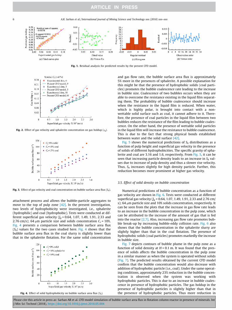
Fig. 1. Residual analysis for predicted results by the present CFD model.
Fig. 2. Effect of gas velocity and sphalerite concentration on gas holdup (eg).
Fig. 3. Effect of gas velocity and coal concentration on bubble surface area flux (Sb).
6 A.R. Sarhan et al. / International Journal of Mining Science and Technology xxx (2018) xxx–xxx
attachment process and allows the bubble-particle aggregates tomove to the top of pulp zone [42]. In the present investigation,two levels of hydrophobicity were investigated, i.e., sphalerite(hydrophilic) and coal (hydrophobic). Tests were conducted at dif-ferent superficial gas velocity (Jg = 0.64, 1.07, 1.49, 1.91, 2.33 and2.76 cm/s); 64 mm particle size and solids concentration Cs = 10%.Fig. 4 presents a comparison between bubble surface area flux(Sb) values for the two cases studied here. Fig. 4 shows that thebubble surface area flux in the coal slurry is slightly lower thanthat in the sphalerite flotation. For the same solid concentration
Fig. 4. Effect of solid hydrophobicity on bubble surface area flux (Sb).
Please cite this article in press as: Sarhan AR et al. CFD model simulation of bubJ Min Sci Technol (2018), https://doi.org/10.1016/j.ijmst.2018.05.004
and gas flow rate, the bubble surface area flux is approximately5% more in the presences of sphalerite. A possible explanation forthis might be that the presence of hydrophobic solids (coal parti-cles) promotes the bubble coalescence rate leading to the increasein bubble size. Coalescence of two bubbles occurs when they areable to overcome the resistance existing in the liquid film separat-ing them. The probability of bubble coalescence should increasewhen the resistance in the liquid film is reduced. When water,which is highly polar, is brought into contact with a non-wettable solid surface such as coal, it cannot adhere to it. There-fore, the presence of coal particles in the liquid film between twobubbles reduces the resistance of the film leading to bubble coales-cence. On the other hand, the presence of wettable solid particlesin the liquid film will increase the resistance to bubble coalescence.This is due to the fact that strong physical bonds establishedbetween water and the solid surface [42].
Fig. 5 shows the numerical predictions of Sb distributions as afunction of pulp height and superficial gas velocity in the presenceof solids of different hydrophobicities. The specific gravity of spha-lerite and coal are 3.16 and 1.6, respectively. From Fig. 5, it can beseen that increasing particle density leads to an increase in Sb val-ues due to increase of pulp density and thus a slower rise velocity.Thus, Sb increases slightly for high density particle. Further, thisreduction becomes more prominent at higher gas velocity.
3.5. Effect of solid density on bubble concentration
Numerical predictions of bubble concentration as a function ofgas velocity are shown in Fig. 6. Tests were conducted at differentsuperficial gas velocity (Jg = 0.64, 1.07, 1.49, 1.91, 2.33 and 2.76 cm/s); 64 mm particle size and 10% solids concentration, respectively. Itcan be seen from the plots that the increase in gas flow rate leadsto an increase in the bubble concentration in the pulp zone, whichcan be attributed to the increase of the amount of gas that is fedinto the reactor [2,7]. Also, increasing gas flow rate promotes bub-ble break-up by increasing bubble-eddy collision rate. Fig. 6 alsoshows that the bubble concentration in the sphalerite slurry areslightly higher than that in the coal flotation. The presence ofhydrophobic solids (coal particles) promotes markedly the increasein bubble size.
Fig. 7 depicts contours of bubble plume in the pulp zone as afunction of solid density at H = 0.1 m. It was found that the pres-ence of solids affects the bubble concentration in the pulp zonein a similar manner as when the system is operated without solids(Fig. 7). The predicted results obtained by the current CFD modelconfirm that the bubble concentration would also decrease withaddition of hydrophobic particle (i.e., coal). Under the same operat-ing conditions, approximately 23% reduction in the bubble concen-tration is observed when the system was working withhydrophobic particles. This is due to an increase in bubble coales-cence in presence of hydrophobic particles. The gas holdup in thepresence of hydrophilic particles is slightly higher than that inthe presence of hydrophobic particles. Thus more reduction in
ble surface area flux in flotation column reactor in presence of minerals. Int

Fig. 5. Numerical predictions of bubble surface area flux (Sb) distributions as a function of pulp height and superficial gas velocity, for 10% volume fraction of solid particles.
Fig. 6. Numerical predictions of bubble concentration as a function of solid densityand gas velocity, for 10% volume fraction of solid particles.
Fig. 7. Bubble plume as a function of solid concentration at H = 0.1 m.
Fig. 8. Number density of bubbles at sphalerite = 5% (by volume) with differentsuperficial gas velocities.
Fig. 9. Number density of bubbles at sphalerite = 10% (by volume) with differentsuperficial gas velocities.
A.R. Sarhan et al. / International Journal of Mining Science and Technology xxx (2018) xxx–xxx 7
the bubble concentration occurs in presence of hydrophobic parti-cles (coal) than hydrophilic sphalerite.
Figs. 8 and 9 show the contours of bubble concentration forvarious gas flow rate (Jg = 0.64–2.76 cm/s) and solid concentration(Cs = 5% and 10%, by volume) at ds = 64 mm in the pulp zone for
Please cite this article in press as: Sarhan AR et al. CFD model simulation of bubJ Min Sci Technol (2018), https://doi.org/10.1016/j.ijmst.2018.05.004
sphalerite slurries. The colour scale given at the left of the graphsdepicts the change in the bubble concentration inside the flotationcolumn. The predicted results obtained by the present CFD modelconfirm that the bubble concentration would also increase withincreasing superficial gas velocity in the collection zone. This isbecause increased gas flowrate leads to an increase in the amountof gas in the reactor [2]. Figs. 8 and 9 also show that the bubbleconcentration at the column center especially near the spargerregion is relatively high. This is due to the fact that the bubblesclose to the bottom are subjected to higher turbulence at the inletregion [7]. This is also explained in Section 3.3 where an increase of
ble surface area flux in flotation column reactor in presence of minerals. Int

8 A.R. Sarhan et al. / International Journal of Mining Science and Technology xxx (2018) xxx–xxx
Sb value indicates lower bubble diameter. These results also showthat increased solid concentration leads to a decrease in the bubbleconcentration in the pulp zone. A possible explanation for thismight be that the concentration number of bubbles is a functionof the gas holdup in the cell. As solids concentration increased,gas holdup decreased leading to a decrease in the concentrationnumber of bubbles. A possible explanation for this might be thatthe presence of solid particles increases the apparent viscosity ofthe liquid phase and thus promoting coalescence rate of the bubblein the pulp zone. This increase in bubble size leads to an increase inthe rise velocity of bubbles leading to a decreased gas holdup athigher solid concentration (Fig. 2).
4. Conclusions
A CFD simulations of three-phase flow (gas, liquid and solid) inflotation column reactor were performed to predict the effects ofsuperficial gas velocities and particle type, density, wettabilityand concentration on the bubble surface area flux (Sb). A mathe-matical model of a gas–liquid–solid flow was built. The numericalpredictions were based on two fluid model, using the Eulerian–Eulerian formulation along with a k-e turbulence approach.Bubble–bubble interactions, such as bubble break-up due toturbulence and bubble coalescence due to the combined effect ofturbulence and laminar shear have been included in the CFD codeby writing subroutines in Fortran. The interfacial exchange of massand momentum, as well as the bubble-particles interactions wereconsidered in the current model. The predicted results by the cur-rent CFD model have been validated against published experimen-tal data of Bhunia, Kundu and Mukherjee [2]. The residual analysisand R2 value indicate that the CFD model was able to predict theeffect of operating parameters on gas holdup with reasonable accu-racy. The results from the present CFD simulations show that thebubble surface area flux (Sb) increases by increasing superficialgas velocity (Jg) and decreases by increasing solid concentration(Cs) and/or hydrophobicity (h) at any given Jg. Approximately 28%reduction in the surface area flux is observed when coal concentra-tion is increased from 0% to 10%, by volume. While for the samesolid concentration and gas flow rate, the bubble surface area fluxis increased by 7% (approx.) in the presences of sphalerite. A possi-ble explanation for this might be that the presence of hydrophobicsolids (coal particles) promotes the bubble coalescence rate lead-ing to the increase in bubble size. Also, it was found that the bubbleconcentration would decrease with the addition of hydrophobicparticle (i.e., coal). For instance, under the same operating condi-tions, approximately 23% reduction in the bubble concentrationis perceived when the system was working with hydrophobicparticles.
Acknowledgement
The authors wish to thank the Higher Committee for EducationDevelopment in Iraq (HCED) for their financial support.
References
[1] Fan MM, Tao D, Zhao YM, Honaker R. Effect of nanobubbles on the flotation ofdifferent sizes of coal particle. Miner Metall Proc 2013;30(3):157–61.
[2] Bhunia K, Kundu G, Mukherjee D. Statistical model for gas holdup in flotationcolumn in presence of minerals. Can Metall Q 2015;54(2):235–46.
[3] Ahmadi R, Khodadadi DA, Abdollahy M, Fan M. Nano-microbubble flotation offine and ultrafine chalcopyrite particles. Int J Min Sci Technol 2014;24(4):559–66.
[4] Fan M, Tao D, Honaker R, Luo Z. Nanobubble generation and its applications infroth flotation (part IV): mechanical cells and specially designed columnflotation of coal. Min Sci Technol (China) 2010;20(5):641–71.
Please cite this article in press as: Sarhan AR et al. CFD model simulation of bubJ Min Sci Technol (2018), https://doi.org/10.1016/j.ijmst.2018.05.004
[5] Ran JC, Liu JT, Zhang CJ, Wang DY, Li XB. Experimental investigation andmodeling of flotation column for treatment of oily wastewater. Int J Min SciTechnol 2013;23(5):665–8.
[6] Shahbazi B, Rezai B, Chelgani SC, Koleini SMJ, Noaparast M. Estimation ofdiameter and surface area flux of bubbles based on operational gas dispersionparameters by using regression and ANFIS. Int J Min Sci Technol 2013;23(3):343–8.
[7] Sarhan AR, Naser J, Brooks G. CFD simulation on influence of suspended solidparticles on bubbles’ coalescence rate in flotation cell. Int J Miner Process2016;146:54–64.
[8] Rahman RM, Ata S, Jameson GJ. The effect of flotation variables on the recoveryof different particle size fractions in the froth and the pulp. Int J Miner Process2012;106:70–7.
[9] Bhunia K, Kundu G, Mukherjee D. Application of statistical analysis on thebubble surface area flux in a column flotation cell. Sep Sci Technol 2015;50(8):1230–8.
[10] Mirgaux O, Ablitzer D, Waz E, Bellot JP. Mathematical modeling and computersimulation of molten aluminum purification by flotation in stirred reactor.Metall Mater Trans B 2009;40(3):363–75.
[11] Bloom F, Heindel TJ. An approximate analytical expression for the probabilityof attachment by sliding. J Colloid Interface Sci 1999;218(2):564–77.
[12] Khan MJH, Hussain MA, Mansourpour Z, Mostoufi N, Ghasem NM, Abdullah EC.CFD simulation of fluidized bed reactors for polyolefin production – a review. JInd Eng Chem 2014;20(6):3919–46.
[13] Sha J, Xie G, Wang H, Liu J, Tang L. Effect of the column height on theperformance of liquid–solid fluidized bed for the separation of coarse slime.Int J Min Sci Technol 2012;22(4):585–8.
[14] Finch JA, Dobby GS. Column flotation; 1990.[15] Gallegos-Acevedo PM, Perez-Garibay R, Uribe-Salas A, Nava-Alonso F. Bubble
load estimation in the froth zone to predict the concentrate mass flow rate ofsolids in column flotation. Miner Eng 2007;20(13):1210–7.
[16] Finch JA, Xiao J, Hardie C, Gomez CO. Gas dispersion properties: bubble surfacearea flux and gas holdup. Miner Eng 2000;13(4):365–72.
[17] Gomez CO, Finch JA. Gas dispersion measurements in flotation cells. Int J MinerProcess 2007;84(1–4):51–8.
[18] Gorain BK, Franzidis JP, Manlapig EV. The empirical prediction of bubblesurface area flux in mechanical flotation cells from cell design and operatingdata. Miner Eng 1999;12(3):309–22.
[19] Hernandez H, Gomez CO, Finch JA. Gas dispersion and de-inking in a flotationcolumn. Miner Eng 2003;16(8):739–44.
[20] Schwarz S, Alexander D. Gas dispersion measurements in industrial flotationcells. Miner Eng 2006;19(6–8):554–60.
[21] Jameson GJ, Nam S, Young MM. Physical factors affecting recovery rates inflotation. Miner Sci Eng 1977;9(3):103–18.
[22] Gorain BK, Franzidis JP, Manlapig EV. Studies on impeller type, impeller speedand air flow rate in an industrial scale flotation cell. Part 4: Effect of bubblesurface area flux on flotation performance. Miner Eng 1997;10(4):367–79.
[23] Hernandez-Aguilar JR, Rao SR, Finch JA. Testing the k-S-b relationship at themicroscale. Miner Eng 2005;18(6):591–8.
[24] Leiva J, Vinnett L, Contreras F, Yianatos J. Estimation of the actual bubblesurface area flux in flotation. Miner Eng 2010;23(11–13):888–94.
[25] Deglon DA, Sawyerr F, O’Connor CT. A model to relate the flotation rateconstant and the bubble surface area flux in mechanical flotation cells. MinerEng 1999;12(6):599–608.
[26] AVL-FIRE, AVL advanced simulation technologies software documentation;2014.
[27] Li WL, Zhong WQ. CFD simulation of hydrodynamics of gas-liquid-solid three-phase bubble column. Powder Technol 2015;286:766–88.
[28] Tomiyama A, Kataoka I, Zun I, Sakaguchi T. Drag coefficients of single bubblesunder normal and micro gravity conditions. JSME Int J B-Fluid T 1998;41(2):472–9.
[29] Sattar MA, Naser J, Brooks G. Numerical simulation of two-phase flow withbubble break-up and coalescence coupled with population balance modeling.Chem Eng Process 2013;70:66–76.
[30] Koh PTL, Schwarz MP. CFD model of a self-aerating flotation cell. Int J MinerProcess 2007;85(1–3):16–24.
[31] Koh PTL, Schwarz MP. CFD modelling of bubble-particle attachments inflotation cells. Miner Eng 2006;19(6–8):619–26.
[32] Huang K, Lin S, Wang JJ, Luo ZH. Numerical evaluation on the intraparticletransfer in butylene oxidative dehydrogenation fixed-bed reactor over ferritecatalysts. J Ind Eng Chem 2015;29:172–84.
[33] Hosseini SH, Shojaee S, Ahmadi G, Zivdar M. Computational fluid dynamicsstudies of dry and wet pressure drops in structured packings. J Ind Eng Chem2012;18(4):1465–73.
[34] Akhtar MA, Tade MO, Pareek VK. Two-fluid Eulerian simulation of bubblecolumn reactors with distributors. J Chem Eng Jpn 2006;39(8):831–41.
[35] Prakash A, Margaritis A, Li H, Bergougnou MA. Hydrodynamics and local heattransfer measurements in a bubble column with suspension of yeast. BiochemEng J 2001;9(2):155–63.
[36] Zhang W, Finch JA. Effect of solids on pulp and froth properties in flotation. JCent South Univ 2014;21(4):1461–9.
[37] Ojima S, Hayashi K, Tomiyama A. Effects of hydrophilic particles on bubblyflow in slurry bubble column. Int J Multiph Flow 2014;58:154–67.
[38] Banisi S, Finch JA, Laplante AR, Weber ME. Effect of solid particles on gasholdup in flotation columns—I. Measurement. Chem Eng Sci 1995;50(14):2329–34.
ble surface area flux in flotation column reactor in presence of minerals. Int

A.R. Sarhan et al. / International Journal of Mining Science and Technology xxx (2018) xxx–xxx 9
[39] Tavera FJ, Escudero R. Effect of solids on gas dispersion characteristics:addition of hydrophobic and hydrophilic solids. J Mex Chem Soc 2012;56(2):217–21.
[40] Grevskott S, Sannæs BH, Dudukovic MP, Hjarbo KW, Svendsen HF. Liquidcirculation, bubble size distributions, and solids movement in two- and three-phase bubble columns. Chem Eng Sci 1996;51(10):1703–13.
Please cite this article in press as: Sarhan AR et al. CFD model simulation of bubJ Min Sci Technol (2018), https://doi.org/10.1016/j.ijmst.2018.05.004
[41] Banisi S, Finch JA, Laplante AR, Weber ME. Effect of solid particles on gasholdup in flotation columns—II. Investigation of mechanisms of gas holdupreduction in presence of solids. Chem Eng Sci 1995;50(14):2335–42.
[42] Sarhan AR, Naser J, Brooks G. CFD analysis of solid particles properties effect inthree-phase flotation column. Sep Purif Technol 2017;185:1–9.
ble surface area flux in flotation column reactor in presence of minerals. Int