international journal of mechanical engineering and...
TRANSCRIPT

International Journal of Mechanical Engineering and Technology (IJMET), ISSN 0976 – 6340(Print),
ISSN 0976 – 6359(Online), Volume 5, Issue 3, March (2014), pp. 104-113, © IAEME
104
OVERVIEW OF FAILURE TREND OF INLET & EXHAUST VALVE
Yuvraj K Lavhale1, Prof. Jeevan Salunke
2
1(M.E.Mechanical, II
nd Year, Deogiri Institute of Engineering and Management Studies,
Aurangabad(MS), India) 2(Associate professor, Mechanical Engineering, Deogiri Institute of Engineering and Management
Studies/ Aurangabad(MS), India)
ABSTRACT
Diesel engine consists of number of vital components, which perform various functions and
are subjected to different forces, thermal loadings and stresses. Inlet & Exhaust valves are most
important components of the diesel engine. The function of Inlet valve is to provide path for desired
air flow to combustion chamber. Function of Exhaust valve is to provide opening, to pass burnt gases
through the cylinder. The opening and closing of inlet and exhaust valve is controlled by valve
mechanism during the engine operation. Valves are subjected to thermal loading because of high
temperature and pressure developed inside the cylinder. This paper focuses on failure trend of inlet
and exhaust valve. Failures take place of inlet and exhaust valve in different manners due to fatigue,
thermal loading, wear, corrosion and erosion which leads to loss of mechanical properties of material
and engine performance etc,.
Keywords: Exhausts Valve, Erosion, Fatigue, Inlet Valve, Thermal Loading, Scavenging, Stress.
1. INTRODUCTION
Valve mechanism is the arrangement of different components which controls the intake and
exhaust process. The operation of timely opening and closing the inlet and outlet valves in
accordance with the firing order of cylinders is performed through valve mechanism. In each cycle
of the operation, the intake and exhaust processes take place in a short span of time. Valve
mechanism components work at high and changing speed. Some components have to withstand high
temperature; therefore valve mechanism components have too much inertia and thermal stress. They
also have poor lubrication, which results in increased wear and influence the correct gas distribution.
Main requirements of the valve mechanism is accurate timing, a large enough area for gas flow,
INTERNATIONAL JOURNAL OF MECHANICAL ENGINEERING
AND TECHNOLOGY (IJMET)
ISSN 0976 – 6340 (Print)
ISSN 0976 – 6359 (Online)
Volume 5, Issue 3, March (2014), pp. 104-113
© IAEME: www.iaeme.com/ijmet.asp
Journal Impact Factor (2014): 7.5377 (Calculated by GISI)
www.jifactor.com
IJMET
© I A E M E
International Journal of Mechanical Engineering and Technology (IJMET), ISSN 0976 – 6340(Print),
ISSN 0976 – 6359(Online), Volume 5, Issue 3, March (2014), pp. 104-113, © IAEME
105
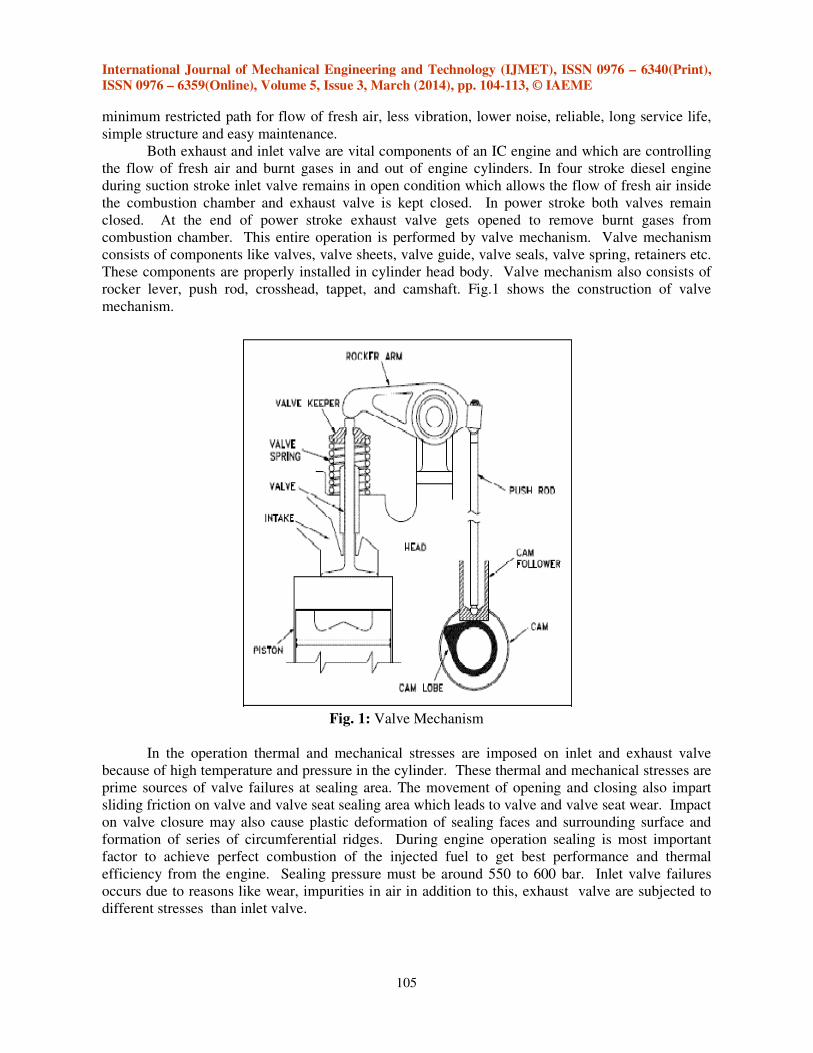
minimum restricted path for flow of fresh air, less vibration, lower noise, reliable, long service life,
simple structure and easy maintenance.
Both exhaust and inlet valve are vital components of an IC engine and which are controlling
the flow of fresh air and burnt gases in and out of engine cylinders. In four stroke diesel engine
during suction stroke inlet valve remains in open condition which allows the flow of fresh air inside
the combustion chamber and exhaust valve is kept closed. In power stroke both valves remain
closed. At the end of power stroke exhaust valve gets opened to remove burnt gases from
combustion chamber. This entire operation is performed by valve mechanism. Valve mechanism
consists of components like valves, valve sheets, valve guide, valve seals, valve spring, retainers etc.
These components are properly installed in cylinder head body. Valve mechanism also consists of
rocker lever, push rod, crosshead, tappet, and camshaft. Fig.1 shows the construction of valve
mechanism.
Fig. 1: Valve Mechanism
In the operation thermal and mechanical stresses are imposed on inlet and exhaust valve
because of high temperature and pressure in the cylinder. These thermal and mechanical stresses are
prime sources of valve failures at sealing area. The movement of opening and closing also impart
sliding friction on valve and valve seat sealing area which leads to valve and valve seat wear. Impact
on valve closure may also cause plastic deformation of sealing faces and surrounding surface and
formation of series of circumferential ridges. During engine operation sealing is most important
factor to achieve perfect combustion of the injected fuel to get best performance and thermal
efficiency from the engine. Sealing pressure must be around 550 to 600 bar. Inlet valve failures
occurs due to reasons like wear, impurities in air in addition to this, exhaust valve are subjected to
different stresses than inlet valve.

International Journal of Mechanical Engineering and Technology (IJMET), ISSN 0976 – 6340(Print),
ISSN 0976 – 6359(Online), Volume 5, Issue 3, March (2014), pp. 104-113, © IAEME
106
Fig. 2: Intake & Exhaust valve
Exhaust valves are exposed to thermal stress more than intake valve because intake valve are
virtually cooled by fresh air. However burnt gases have very high temperature in the range of 800 to
10000C because of this frequency of failure of exhaust valve is higher than inlet valve. In turbo
charge engines the cooling of inlet and exhaust valve is taken care by scavenging operation. Clean
fresh air is cooled by intercooler and then pumped into the combustion chamber during the suction
stroke and during the scavenging operation. This process receives adequate cooling of valve and
valve seat surface and prevents from premature failure. Depositions building up on valve face and
valve seats leads to poor sealing and seat can have an insulating effect which causes poor cooling
and makes the valve run hot. If deposition is built up on valve face in the form of one spot, then poor
sealing appears. This poor sealing leads to leaking of the combustion and creates hot spot on valve
sealing face which in turn results in channeling effect.
The deposition on valve seat, valve face, valve stem, is from combined reaction of impure
contaminated fuel and lubricating oil. The chemicals like sulfur vanadium and sodium content in fuel
oxidizes during the combustion process to form sulfur dioxide, sulfur trioxide, sodium oxide and
vanadium pent oxide. These oxides act with each other and calcium contents in lubricating oil to
form low melting point salts. These salt particles get deposited on valve surfaces in their molten
state. These salt particles get cooled sufficiently to adhere to valve stem and valve spindle and do not
get carried away by the exhaust gases. As operating temperature is more than 6000C the deposited
salts change into molten state. This molten state salts flow along the grain boundaries depending on
valve material and dissolves the protective oxide on the grain boundaries. This phenomena is called
inter granular corrosion, which leads to burning of the valve sealing face.
There is another important type of valve failures i.e valve breakage. Valve failures due to
breakage are called fatigue failures. During engine operation valves are subjected to cyclic loading,
opening and closing causes loading and unloading of stresses on the valve. If this cyclic loading on
the valve is beyond the limit, then valve failure due to fatigue occurs at weakest surface point of the
valve. In stray cases valves also fail due to impact loading, when valve drops take place due to some
of the reasons like over speeding, valve lock loosening. Any kind of valve failure cannot be
neglected since it may cause sluggish performance or permanent stoppage of engine operation.
Failure of valve trends and modes can be summarized in categories like wear failure, valve
face recession, fatigue failures, thermal fatigue, erosion/corrosion of valve, overheating of valves,
carbon deposition of valves etc., The available research literatures regarding valve failure trends

International Journal of Mechanical Engineering and Technology (IJMET), ISSN 0976 – 6340(Print),
ISSN 0976 – 6359(Online), Volume 5, Issue 3, March (2014), pp. 104-113, © IAEME
107
indicate that valve design is a critical and complicated task since during operation, valve is subjected
to various loading patterns throughout working of diesel engine.
Diesel engine operates at different temperature level range, which depends on use of fuel,
application, RPM, torque, BHP etc.,
In naturally aspirated engine temperature are in the range of
a) At Pre cleaner/Air Filter – 30 to 350C subject to ambient temperature.
b) At Intake port of Cylinder head – 40 to 450
C
c) Exhaust temperature before silencer – 475 to 5250 C
In Turbocharged/Supercharge engine temperature are in the range of
a) At Pre cleaner/Air Filter – 30 to 350C subject to ambient temperature.
b) At Intercooler inlet - 60 to 700
C
c) At Intake port of Cylinder head (At intercooler outlet) – 50 to 600
C
d) Exhaust temperature before silencer – 425 to 4750 C
Naresh Kr. Raghuwanshi & et al [1] kept focus on various failure modes of IC engine inlet &
exhaust valves. The failure mainly due to fatigue at high temperature, high operating temperature
effects on mechanical properties of valve materials like hardness and yield strength. Wear failure
which is due to impact loading, and wear rate that depends on load and time. This is helpful for
researchers to develop the valve materials to achieve a prolonged life.
Nurten Vardar & et al[2] investigated the failure of Exhaust Valve Failure in Heavy duty
Diesel Engine. This was carried out by using several experimental tests methods like optical
emission spectroscopy, optical microscopy, scanning electron microscopy SEM and EDX. They
conclude that the valve was failed and broken down prior to its desired service life.
S. M. Jafari, & et al. [3] presented the potential of acoustic emission (AE) technique to detect
valve damage in internal combustion engines. The cylinder head of a spark-ignited engine was used
as the experimental setup. The effect of three types of valve damage (clearance, semi-crack, and
notch) on valve leakage was investigated.
R. V. Wanjari & et al [5] Failure analysis of Camshaft is done either by experimental or finite
element analysis. The result obtain by the finite element analysis is an approximate of the component
failure.
Dr. Ing. Holger & et al [6] Optimize service intervals as well as to perform the correct and
necessary work & to reduce the operating costs over a long period of service life by means of a high
quality service program.
Tomasz Lus & et al [7] presented Marine diesel engines new diagnostics method which can
be used on marine high speed diesel engines & presented method which is based on vibration signal
analyzing in crankshaft revolution angle domain. By using this method checking angle of fuel
injection or timing in valve gear mechanism without stopping the engine and dismantling it is
possible.
W. Tuckart [8] presented failure analysis of pushrod valve train of stationary diesel engines.
Ajay Pandey & et al [9] presented failures of automobile valves and discussed using the
Scanning Electron Microscope (SEM). Specimens were prepared from failed engine valves and also
new valves were also analyzed for the purpose of comparison. It was carried out by image analysis of
specimens of failed and new valves by using adequate magnification.
International Journal of Mechanical Engineering and Technology (IJMET), ISSN 0976 – 6340(Print),
ISSN 0976 – 6359(Online), Volume 5, Issue 3, March (2014), pp. 104-113, © IAEME
108
2. MODES OF FAILURES
Following are different types of failure and their causes of inlet & exhaust valve.
2. 1. Failure Due to Fatigue
The meaning of word fatigue means “to tire” which is derived from latin word “Fatigue”. In
engineering language/terminology fatigue failure is a progressive structural damage of the material
of the component when the component under goes cyclic loading. There are two important
categories of fatigue failure a) Mechanical failure due to fluctuating stresses due to cyclic load at
high temperature. b) Thermal fatigue due to cyclic changes in component material temperature.
Corrosion fatigue failure due to cyclic loads applied on corroded materials. Fretting fatigue
failure - due to cyclic stresses together with the oscillatory motion and frictional sliding between
surfaces etc.. Fatigue failure occurs at stresses that are well below the yield point of the material [3].
Diesel Engine inlet and exhaust valves are subjected to repeat cyclic loading due to valve train
dynamics. Due to repeated loading results in materials failing well below the yield strength, when the
material is subjected to fatigue, one or more tiny cracks usually start developing in the material, and
these grow until complete failure occurs.
There are different types of fatigue mechanisms: thermal fatigue, high-cycle fatigue, low-
cycle fatigue, surface fatigue, bending fatigue, corrosion fatigue, torsion fatigue, and fretting fatigue.
In valves, some of the more common failures are due to thermal fatigue, corrosion fatigue, and low
and high-cycle fatigue.
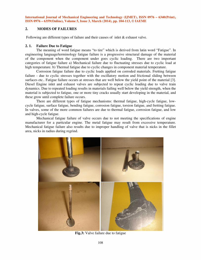
Mechanical fatigue failure of valve occurs due to not meeting the specifications of engine
manufacturer for a particular engine. The metal fatigue may result from excessive temperature.
Mechanical fatigue failure also results due to improper handling of valve that is nicks in the fillet
area, nicks in radius during regrind.
Fig.3: Valve failure due to fatigue
International Journal of Mechanical Engineering and Technology (IJMET), ISSN 0976 – 6340(Print),
ISSN 0976 – 6359(Online), Volume 5, Issue 3, March (2014), pp. 104-113, © IAEME
109
2.2. Failures Due to High Temperature
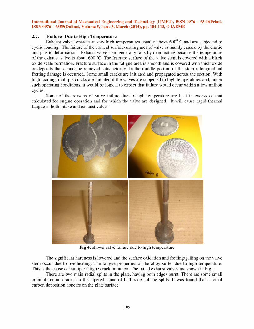
Exhaust valves operate at very high temperatures usually above 6000 C and are subjected to
cyclic loading. The failure of the conical surface/sealing area of valve is mainly caused by the elastic
and plastic deformation. Exhaust valve stem generally fails by overheating because the temperature
of the exhaust valve is about 600 ºC. The fracture surface of the valve stem is covered with a black
oxide scale formation. Fracture surface in the fatigue area is smooth and is covered with thick oxide
or deposits that cannot be removed satisfactorily. In the middle portion of the stem a longitudinal
fretting damage is occurred. Some small cracks are initiated and propagated across the section. With
high loading, multiple cracks are initiated if the valves are subjected to high temperatures and, under
such operating conditions, it would be logical to expect that failure would occur within a few million
cycles.
Some of the reasons of valve failure due to high temperature are heat in excess of that
calculated for engine operation and for which the valve are designed. It will cause rapid thermal
fatigue in both intake and exhaust valves
Fig 4: shows valve failure due to high temperature
The significant hardness is lowered and the surface oxidation and fretting/galling on the valve
stem occur due to overheating. The fatigue properties of the alloy suffer due to high temperature.
This is the cause of multiple fatigue crack initiation. The failed exhaust valves are shown in Fig.,
There are two main radial splits in the plate, having both edges burnt. There are some small
circumferential cracks on the tapered plane of both sides of the splits. It was found that a lot of
carbon deposition appears on the plate surface

International Journal of Mechanical Engineering and Technology (IJMET), ISSN 0976 – 6340(Print),
ISSN 0976 – 6359(Online), Volume 5, Issue 3, March (2014), pp. 104-113, © IAEME
110
2.3. Failure of Valve Due to Erosion-Corrosion
As discussed above, in the diesel engine exhaust valves operate at very high temperature. The
scale formations are on the valve which corrodes the surface of valve due to exhaust flue gases.
Surface material is removed in service life and it is the result of erosion by small, solid, impacting
particles. In most elevated - temperature erosion environments, the eroding surface is undergoing
corrosion as well as erosion. In one test series, a nickel oxide scale was formed up to 100 µm thick at
1000ºC on commercially pure nickel
The erosion-corrosion of exhaust valves (valve guttering) is an important cause of failure of
internal combustion engines valves. Hot gases escaping at seat of an adjacent valve are directed at
shot-blasted fillet area and erode surface material.
Valve guttering generally occurs because of flow of exhaust gas across the valve face surface,
resulting in the formation of a radial channel or gutter. Typical causes of gas leakage include valve
distortion, face pinning and degradation of face deposits.
Fig. 5: Failure of valve due to erosion-corrosion
2.4. Failure of Valve Due to Wear
At the sealing face of valve and valve seat which slide on valve stem guide, wear failure
occurred at this area. There are two major factors, due to which wear failure occurs a) the impact
force between sealing face of valve and seat insert b) due to sliding of the valve on the seat insert
during the action of combustion pressure. The origin of valve face wear, is improper valve spring
tension, high speed and excessive heat, loose valve adjustment, and excessive abrasive dirt in intake.
Continued operation with this type of wear leads to “cupping” and / or mechanical fatigue. It is
theorized that “initial” valve face wear rate is greater than the rate of wear after break in, under
normal condition.

International Journal of Mechanical Engineering and Technology (IJMET), ISSN 0976 – 6340(Print),
ISSN 0976 – 6359(Online), Volume 5, Issue 3, March (2014), pp. 104-113, © IAEME
111
Fig. 6: Failure of valve due to wear
3. METHODS OF FRACTURE ANALYSIS
The failure analysis of inlet & exhaust valve of diesel engine can be carried out by using the
following tools and techniques:
3.1 Microscope The objects which are too small and which are not visible by naked eyes are inspected using
microscope. The technique and science of investigating such type small object by the microscope
instrument is called microscopy. Microscopic means invisible to the eye unless aided by a
microscope.
3.2 Sample Preparation In the analysis process sample preparation is essential stage. It takes place between sample
taking and measuring the prepared sample by means of X-ray spectrometry or X-ray diffraction.
Depending on the type of sample, there are various ways to prepare it in such a way that the sample
is ready for measurement.
3.3 Spectroscopic Analysis Spectroscopy is the study of the interaction between matter and radiated energy.
Spectroscopy was originated through the study of visible light dispersed according to its wavelength,
e.g., by a prism. Later the concept was expanded greatly to comprise any interaction with irradiative
energy as a function of its wavelength or frequency. Spectroscopic data is often represented by a
spectrum, a plot of the response of interest as a function of wavelength or frequency.

International Journal of Mechanical Engineering and Technology (IJMET), ISSN 0976 – 6340(Print),
ISSN 0976 – 6359(Online), Volume 5, Issue 3, March (2014), pp. 104-113, © IAEME
112
3.4 Scanning Electron Microscopy
The scanning electron microscope (SEM) is a type of electron microscope that images the
sample surface by scanning it with a high-energy beam of electrons in a raster scan pattern. The
electrons interact with the atoms that make up the sample producing signals that contain information
about the sample's surface topography, composition and other properties such as electrical
conductivity.
4. RESULT & DISCUSSION
Looking towards the mode and root causes of intake and exhaust valve failures, while
designing the valve important factors should be taken into account. These important factors are
chemical composition of valve material, engineering dimensions and tolerances, operating
temperatures, duty cycle, equipment applications, atmospheric condition, HP rating, pick torque
rating, RPM rating. Besides of design parameter, operation and maintenance plays very important
role for the failure of valves. For cause of fatigue failure, care should be taken likewise over
speeding of the engine, foreign material entry during induction, hydraulic locks etc,. For thermal
loading engine operating temperature is the key factor so intake & exhaust gas temperature should be
controlled by tracking of overloading, fuel quality and cooling system performance. In case of wear
failure valve adjustment and cleanliness of fresh air is most important. Dust entry in intake port is
greatest enemy which causes early wear. Poor compression, scale formation, are the prime sources of
valve failure due to corrosion-erosion.
5. CONCLUSION
In the Diesel engine various failure mode/trend affects the valve failures. Valve failures
occur due to mechanical fatigue, thermal fatigue, thermo mechanical fatigue which is due to cyclic
load, cyclic stresses. Fatigue failure occur at stresses that are well below the yield point of the
material. Failure due to high temperature is caused by elastic and plastic deformation of the valve
material. Failure of valve due to erosion and corrosion is the result of scale formation on the valve
surface due to exhaust flue gases. Failure of valve due to wear is the result of impact force between
sealing face of valve seat and seat insert. It is also due to sliding of the valve on seat insert during the
action of combustion pressure. The frequency of exhaust valve failure is more than the intake valve.
Any kind of valve failures affects on performance & efficiency of the engine, so due importance and
attention should be given while designing of the intake & exhaust valve by considering engineering
and operational factors.
6. ACKNOWLEDGMENT
The authors wish to acknowledge the support rendered by Mr. Suresh S. Rau (HOD) and Mr.
Indrajit Rau (Head-Business Development) & Mr. Sandeep Kudke (Manager- Recon) of Trinity
Mahalasa Durga Sales & Services. The authors also acknowledge the support of Dr. Ulhas Shiurkar,
Director, Deogiri Institute of Engineering and Management Studies.
REFERENCES
Journal Papers [1] Naresh Kr. Raghuwanshi, Ajay Pandey, R. K. Mandloi, “Failure Analysis of Internal
Combustion Engine Valves: A Review,” International Journal of Innovative Research in
Science, Engineering and Technology, Vol. 1, Issue 2, December 2012.

International Journal of Mechanical Engineering and Technology (IJMET), ISSN 0976 – 6340(Print),
ISSN 0976 – 6359(Online), Volume 5, Issue 3, March (2014), pp. 104-113, © IAEME
113
[2] Nurten Vardar, Ahmet Ekerim, “Investigation of Exhaust Valve Failure in Heavy – duty
Diesel Engine,” Gazi University Journal of Science 23(4):493-499 (2010).
[3] S. M. Jafari, H.Mehdigholi, andM. Behzad, “Valve Fault Diagnosis in Internal Combustion
Engines Using Acoustic Emission and Artificial Neural Network,” Hindawi Publishing
Corporation Shock and Vibration Volume 2014, Article ID 823514, pp 1-9.
[4] M. Azadi1, M. Roozban, A. Mafi, “Failure analysis of an intake valve in a gasoline engine,”
The Journal of Engine Research, Vol. 26 (spring 2012), pp. 03-09.
[5] R. V. Wanjari, T. C. Parshiwanikar, “Failure of Camshaft,” International Journal of
Innovative Technology and Exploring Engineering, Volume-2, Issue-6, May 2013.
[6] Dr. Ing. Holger Fellmann, Thomas Grob, Torsten Ludwig, “Typical wear mechanism of 2-
stroke exhaust valves,” Marine Propulsion conference 2004.
[7] Tomasz Lus, Marek Lutowicz , “ Marine Diesel Engines Diagnostics,” Research papers of
Lithuanian University of Agriculture, 2010, Vol 42, No 2-3, 141 – 149.
[8] W. Tuckart, “Failure Analysis of Pushrod Valve Train of Stationary Diesel Engine,”
International Workshop o f Tribology Tribaires 2013 May 7th to 9th 2013, pp 40-41.
[9] Ajay Pandey, R. K. Mandloi, “Effects of High Temperature on the Microstructure of
Automotive Engine Valves,” International Journal of Engineering Research and Applications,
Vol. 4, Issue 3 (Version 1), March 2014, pp.122-126.
[10] Ch. Sreenivasa Rao, Bk.Venkataramu, Dr.M.M.Nayak and Dr.E.S.Prakash, “Micro Fluidic
Valve for Satellite Propulsion System”, International Journal of Mechanical Engineering &
Technology (IJMET), Volume 4, Issue 4, 2013, pp. 171 - 179, ISSN Print: 0976 – 6340,
ISSN Online: 0976 – 6359.
[11] Imran M Quraishi and Madhuvi S Harne, “Stress Analysis and Optimization of Crankshaft
under Dynamic Loading”, International Journal of Mechanical Engineering & Technology
(IJMET), Volume 3, Issue 3, 2012, pp. 429 - 437, ISSN Print: 0976 – 6340, ISSN Online:
0976 – 6359.
[12] Chitthaarth.M.R, Charles Dhonynaveen.I.A, Sunil Kumar.G and Dr.K.Manivannan, “A Study
and Analysis on HCCI Engine's Inlet Valve”, International Journal of Mechanical
Engineering & Technology (IJMET), Volume 3, Issue 3, 2012, pp. 545 - 554, ISSN Print:
0976 – 6340, ISSN Online: 0976 – 6359.