international iso standard 13918 - betawelding.irbetawelding.ir/en/images/iso_13918.pdf · iso...
TRANSCRIPT

Reference numberISO 13918:2008(E)
© ISO 2008
INTERNATIONAL STANDARD
ISO13918
Second edition2008-02-15
Welding — Studs and ceramic ferrules for arc stud welding
Soudage — Goujons et bagues céramiques pour le soudage à l'arc des goujons

ISO 13918:2008(E)
PDF disclaimer This PDF file may contain embedded typefaces. In accordance with Adobe's licensing policy, this file may be printed or viewed but shall not be edited unless the typefaces which are embedded are licensed to and installed on the computer performing the editing. In downloading this file, parties accept therein the responsibility of not infringing Adobe's licensing policy. The ISO Central Secretariat accepts no liability in this area.
Adobe is a trademark of Adobe Systems Incorporated.
Details of the software products used to create this PDF file can be found in the General Info relative to the file; the PDF-creation parameters were optimized for printing. Every care has been taken to ensure that the file is suitable for use by ISO member bodies. In the unlikely event that a problem relating to it is found, please inform the Central Secretariat at the address given below.
COPYRIGHT PROTECTED DOCUMENT © ISO 2008 All rights reserved. Unless otherwise specified, no part of this publication may be reproduced or utilized in any form or by any means, electronic or mechanical, including photocopying and microfilm, without permission in writing from either ISO at the address below or ISO's member body in the country of the requester.
ISO copyright office Case postale 56 • CH-1211 Geneva 20 Tel. + 41 22 749 01 11 Fax + 41 22 749 09 47 E-mail [email protected] Web www.iso.org
Published in Switzerland
ii © ISO 2008 – All rights reserved

ISO 13918:2008(E)
© ISO 2008 – All rights reserved iii
Contents Page
Foreword............................................................................................................................................................. v Introduction ....................................................................................................................................................... vi 1 Scope ..................................................................................................................................................... 1 2 Normative references ........................................................................................................................... 1 3 Terms and definitions........................................................................................................................... 2 4 Symbols and abbreviated terms ......................................................................................................... 2 5 Requirements ........................................................................................................................................ 3 5.1 Ordering information............................................................................................................................ 3 5.2 Dangerous substances ........................................................................................................................ 3 5.3 Product requirements........................................................................................................................... 3 5.4 Durability ............................................................................................................................................... 5 6 Testing for conformity evaluation....................................................................................................... 5 6.1 General................................................................................................................................................... 5 6.2 Testing for dangerous substances ..................................................................................................... 5 6.3 Testing of dimensional requirements of the studs ........................................................................... 5 6.4 Testing of mechanical characteristics of studs ................................................................................ 5 6.5 Weldability ............................................................................................................................................. 6 7 Evaluation of conformity...................................................................................................................... 6 7.1 General................................................................................................................................................... 6 7.2 Initial type testing ................................................................................................................................. 6 7.3 Factory production control (FPC) ....................................................................................................... 7 8 Documentation of test results ............................................................................................................. 9 9 Dimensions of studs........................................................................................................................... 10 9.1 General................................................................................................................................................. 10 9.2 Threaded stud (PD)............................................................................................................................. 10 9.3 Threaded stud with reduced shaft (RD)............................................................................................ 12 9.4 Unthreaded stud (UD)......................................................................................................................... 13 9.5 Stud with internal thread (ID)............................................................................................................. 14 9.6 Shear connector (SD) ......................................................................................................................... 15 9.7 Threaded stud with flange (PS) ......................................................................................................... 16 9.8 Unthreaded stud (US) ......................................................................................................................... 18 9.9 Stud with internal thread (IS)............................................................................................................. 19 9.10 Threaded stud (PT) ............................................................................................................................. 20 9.11 Unthreaded stud (UT) ......................................................................................................................... 21 9.12 Stud with internal thread (IT) ............................................................................................................. 22 10 Dimensions of ceramic ferrules ........................................................................................................ 23 10.1 General................................................................................................................................................. 23 10.2 Ceramic ferrule for threaded stud (PF)............................................................................................. 23 10.3 Ceramic ferrule for unthreaded stud and shear connector (UF) ................................................... 24 10.4 Ceramic ferrule for threaded stud with reduced shaft (RF)............................................................ 25 11 Manufacture and finish....................................................................................................................... 25 11.1 Threaded studs (PD), unthreaded studs (UD), threaded studs with reduced shaft (RD) ............ 25 11.2 Shear connectors (SD) ....................................................................................................................... 25 12 Inspection ............................................................................................................................................ 26 12.1 General................................................................................................................................................. 26 12.2 Chemical analysis............................................................................................................................... 26

ISO 13918:2008(E)
iv © ISO 2008 – All rights reserved
12.3 Mechanical tests ................................................................................................................................. 26 12.4 Sample size.......................................................................................................................................... 26 13 Marking................................................................................................................................................. 27 13.1 Studs .................................................................................................................................................... 27 13.2 Ceramic ferrules.................................................................................................................................. 27 14 Designation.......................................................................................................................................... 27 14.1 Studs .................................................................................................................................................... 27 14.2 Ceramic ferrules.................................................................................................................................. 28 Annex A (informative) Mass of studs.............................................................................................................. 29 Bibliography ..................................................................................................................................................... 32

ISO 13918:2008(E)
© ISO 2008 – All rights reserved v
Foreword
ISO (the International Organization for Standardization) is a worldwide federation of national standards bodies (ISO member bodies). The work of preparing International Standards is normally carried out through ISO technical committees. Each member body interested in a subject for which a technical committee has been established has the right to be represented on that committee. International organizations, governmental and non-governmental, in liaison with ISO, also take part in the work. ISO collaborates closely with the International Electrotechnical Commission (IEC) on all matters of electrotechnical standardization.
International Standards are drafted in accordance with the rules given in the ISO/IEC Directives, Part 2.
The main task of technical committees is to prepare International Standards. Draft International Standards adopted by the technical committees are circulated to the member bodies for voting. Publication as an International Standard requires approval by at least 75 % of the member bodies casting a vote.
Attention is drawn to the possibility that some of the elements of this document may be the subject of patent rights. ISO shall not be held responsible for identifying any or all such patent rights.
ISO 13918 was prepared by Technical Committee ISO/TC 44, Welding and allied processes, Subcommittee SC 10, Unification of requirements in the field of metal welding.
This second edition cancels and replaces the first edition (ISO 13918:1998), which has been technically revised.

ISO 13918:2008(E)
vi © ISO 2008 – All rights reserved
Introduction
The range of types of studs specified in this International Standard represents customary applications.
This International Standard can be used in all fields of the metal-working industry.

INTERNATIONAL STANDARD ISO 13918:2008(E)
© ISO 2008 – All rights reserved 1
Welding — Studs and ceramic ferrules for arc stud welding
1 Scope
This International Standard specifies:
⎯ requirements for studs and ceramic ferrules for arc stud welding;
⎯ dimensions, materials, mechanical properties and, when required, conditions of evaluation of conformity.
Table 1 shows types of studs and the symbols for studs and ceramic ferrules that are covered by this document.
Table 1 — Types of studs and symbols for studs and ceramic ferrules
Welding technique Type of studa Symbol for studs
Symbol for ceramic ferrules
threaded stud (pitch) PD PF
threaded stud with reduced shaft RD RF
unthreaded stud UD UF
stud with internal thread ID UF
Drawn arc stud welding with ceramic ferrule or shielding gas
shear connector SD UF
threaded stud with flange (pitch) PS —
unthreaded stud US — Short-cycle drawn arc stud welding
stud with internal thread IS —
threaded stud (pitch) PT —
unthreaded stud UT — Stud welding with tip ignition
stud with internal thread IT —
a Further types of stud and ceramic ferrules can be specified as required for special applications.
2 Normative references
The following referenced documents are indispensable for the application of this document. For dated references, only the edition cited applies. For undated references, the latest edition of the referenced document (including any amendments) applies.
ISO 898-1, Mechanical properties of fasteners made of carbon steel and alloy steel — Part 1: Bolts, screws and studs
ISO 3506-1, Mechanical properties of corrosion-resistant stainless-steel fasteners — Part 1: Bolts, screws and studs
ISO 4042, Fasteners — Electroplated coatings

ISO 13918:2008(E)
2 © ISO 2008 – All rights reserved
ISO 4759-1, Tolerances for fasteners — Part 1: Bolts, screws, studs and nuts — Product grades A, B and C
ISO 4964, Steel — Hardness conversions
ISO 6892, Metallic materials — Tensile testing at ambient temperature
ISO 6947, Welds — Working positions — Definitions of angles of slope and rotation
ISO 14555, Welding — Arc stud welding of metallic materials
ISO/TR 15608, Welding — Guidelines for a metallic materials grouping system
EN 573-3, Aluminium and aluminium alloys — Chemical composition and form of wrought products — Part 3: Chemical composition and form of products
EN 1301-2, Aluminium and aluminium alloys — Drawn wire — Part 2: Mechanical properties
EN 10088-1, Stainless steels — Part 1: List of stainless steels
EN 12166, Copper and copper alloys — Wire for general purposes
3 Terms and definitions
For the purposes of this document, the terms and definitions given in ISO 14555 and the following apply.
3.1 inspection lot arrangement of units of which a random sample is taken for testing and which requires the same chemical composition of the raw material, the same diameter of the finished product and the same manufacturing procedure during the stud production
3.2 manufacturing lot quantity of studs of a single designation including type of stud, size, property class and material, manufactured from bar, wire, rod or flat product from a single cast, processed through the same or similar steps at the same time or over a continuous time period through the same heat treatment and/or coating process, if any
NOTE Same heat treatment or coating process means:
⎯ for a continuous process, the same treatment cycle without any setting modification;
⎯ for a discontinuous process, the same treatment cycle for identical consecutive loads (batches).
The manufacturing lot can be split into a number of manufacturing batches for processing purposes and then reassembled into the same manufacturing lot.
[Adapted from ISO 15330:1999, definition 3.3]
4 Symbols and abbreviated terms
b length of the thread
cd depth of the crack in the head
d1 nominal diameter
d2 diameter at the weld area
d3 diameter of the weld collar

ISO 13918:2008(E)
© ISO 2008 – All rights reserved 3
d4 diameter of the tip
d5 head diameter of headed studs
D6 internal thread diameter
D7 nominal diameter of the ceramic ferrule
d8 grip diameter
d9 base diameter of the ceramic ferrule
h1 height of the flange
h2 height of the ceramic ferrule
h3 height of the head on headed stud
h4 height of the weld collar
h5 height of the unthreaded part of stud types PS and PT
l1 overall length of the stud (excluding aluminium ball or welding tip)
l2 nominal length of the stud
l3 length of the welding tip
y length of the unthreaded part
α face angle
5 Requirements
5.1 Ordering information
At the time of order the manufacturer shall obtain the following information:
a) reference to this International Standard if the purchaser demands compliance;
b) quantities to be delivered;
c) complete product designation;
d) other requirements as agreed with the purchaser (e.g. low-temperature requirements).
5.2 Dangerous substances
Materials used in products shall not release any dangerous substances in excess of the maximum levels permitted in the relevant regulations of the state of destination.
5.3 Product requirements
5.3.1 Dimensions and tolerances on dimensions, form and position
Dimensions and tolerances on dimensions, form and position shall be in accordance with the requirements given in Clause 9.
For coated threaded studs the tolerances shall apply before coating.

ISO 13918:2008(E)
4 © ISO 2008 – All rights reserved
5.3.2 Coating
Unless otherwise specified, studs PS, US, IS, PT, UT, IT of property class 4.8 shall be supplied with electroplated copper coating (C1E).
5.3.3 Materials and mechanical characteristics
5.3.3.1 General
The materials listed in Table 2 shall be used, under the provisions of 5.3.4.
The mechanical characteristics of the studs shall comply with the specifications in Table 2.
5.3.3.2 Shear strength
Shear strength shall be checked by testing the minimum tensile strength of the studs.
Table 2 — Materials and mechanical characteristics of finished studs
Symbol Material/ Material group/ Property class
Standard Mechanical properties of the finished stud
4.8 ISO 898-1 See ISO 898-1 PD RD UD ID
A2-50, A2-70, A4-50, A4-70, A5-50, A5-70 ISO 3506-1 See ISO 3506-1
SD1 Rm W 450 N/mm2 ReH W 350 N/mm2 A5 W 15 %
SD2
Material group 1 with the limits:
C u 0,2 % a
CEV u 0,35 a
Al W 0,02 % a, b
ISO/TR 15608 Rm = 400 N/mm2 to 550 N/mm2 ReH W 235 N/mm2 Rp0,2 W 235 N/mm2 A5 W 20 %
SD3 1.4301
1.4303 EN 10088-1
Rm = 500 N/mm2 to 780 N/mm2 Rp0,2 W 350 N/mm2 A5 W 25 %
4.8 ISO 898-1 See ISO 898-1 PS US IS A2-50 ISO 3506-1 See ISO 3506-1
4.8 ISO 898-1 See ISO 898-1
A2-50 ISO 3506-1 See ISO 3506-1
CuZn37 EN 12166 Rm W 370 N/mm2
1050A EN 573-3 Rm W 100 N/mm2
PT
UT
IT 5754 EN 1301-2 Rm W 230 N/mm2
a Values from the ladle analysis.
b If other elements for killing are used, they shall be reported in the inspection document.

ISO 13918:2008(E)
© ISO 2008 – All rights reserved 5
5.3.4 Weldability
Only weldable materials shall be used for studs.
Non-alloyed steel studs are weldable if the hardness increase is low. In general this is the case when the carbon content is u 0,20 %. Free-cutting steel studs are generally not weldable. Killed materials shall be used.
Austenitic stainless steel studs are generally weldable. Free-cutting steel studs are generally not weldable.
5.4 Durability
The durability of studs is dependent on their use and the environmental exposure to which they are subject.
The mechanical durability of studs is assured for a reasonable economic working life if the studs comply with the requirements of this International Standard.
6 Testing for conformity evaluation
6.1 General
When a conformity evaluation is required, 6.2 to 6.5 apply.
6.2 Testing for dangerous substances
Release of dangerous substances may be assessed indirectly by controlling the content of the substances in the materials used.
6.3 Testing of dimensional requirements of the studs
The dimensions of the studs given in Tables 6 to 16 shall be checked by standard gauges or measuring equipment with an accuracy u 10 % of the given tolerances.
6.4 Testing of mechanical characteristics of studs
The mechanical characteristics of studs shall be tested in accordance with Table 3.
Table 3 — Mechanical characteristics of studs to be tested
Reference standard
Threaded studs Mechanical characteristic Test Carbon steel
and alloy steel Stainless steel
Unthreaded studs
Elongation
Tensile strength
Yield strength
Shear strength
Tensile test ISO 898-1 ISO 3506-1 ISO 6892

ISO 13918:2008(E)
6 © ISO 2008 – All rights reserved
The tensile test to be used shall be a full-size tensile test. However, if the dimensions of the studs do not allow a full-size tensile test, the test may be carried out on the raw material provided the mechanical properties corresponding to those of the current part of the stud are not modified by the manufacturing process.
If tensile testing is not possible, a hardness test shall be carried out for ferritic materials, thus determining the tensile strength in accordance with ISO 4964. The particular properties of the cold-formed material, especially in the peripheral zone, shall be taken into account. For cold-formed studs, the mean value of a minimum of three test points shall be determined, whereas the whole cross-section shall be included. This mean value shall achieve at least the tensile strength according to Table 3. For the rest, the mechanical properties of the raw material shall be used.
The correlation of hardness and tensile strength is laid down likewise in ISO/TR 10108.
6.5 Weldability
A material is considered weldable if a qualified welding procedure can be developed for the material (see ISO 14555).
7 Evaluation of conformity
7.1 General
When an evaluation of conformity is required, 7.2 and 7.3 apply.
The conformity of the studs to the requirements of this International Standard shall be demonstrated by:
⎯ initial type testing;
⎯ factory production control by the manufacturer, including product assessment.
For the purposes of testing, the products may be grouped into families where it is considered that the selected properties are common to all the products within that family.
7.2 Initial type testing
7.2.1 General
An initial type test is the complete set of tests or other procedures determining the performance of samples of products representative of the product type.
Initial type testing shall be performed to show conformity with this International Standard on its first use for products being put on to the market and:
⎯ at the beginning of the production of a new type of stud or different raw material;
⎯ at the beginning of a new or modified method of production.
In the case of products for which initial type testing in accordance with this International Standard was already performed, testing may be reduced:
⎯ if it has been established that the performance characteristics compared with the products already tested have not been affected or
⎯ in accordance with the rules for grouping and/or direct application or application by extrapolation of test results.
ISO 13918:2008(E)
© ISO 2008 – All rights reserved 7
NOTE Studs CE marked in accordance with appropriate specifications may be presumed to have the performance stated with the CE marking, although this does not replace the responsibility of the stud manufacturer to ensure that the stud is correctly designed and has the necessary performance values to meet the design.
7.2.2 Characteristics
All characteristics in Clause 5 shall be subject to initial type testing, with the following exception:
⎯ release of dangerous substances may be assessed indirectly by controlling the content of the substance concerned.
7.2.3 Use of historical data
Tests previously performed on the same products in accordance with the provisions of this International Standard (same characteristics, test method, sampling procedure, system of attestation of conformity, etc.) may be taken into account.
7.2.4 Sampling, testing and conformity criteria
7.2.4.1 Sampling
Initial type testing shall be performed on samples of products representative of the manufactured product type.
7.2.4.2 Testing and conformity criteria
The number of studs to be tested shall be in accordance with the Table 4. All samples shall pass the test.
The results of all type tests shall be recorded and held by the manufacturer for at least ten years after the products to which the type test refers ceases to be placed on the market.
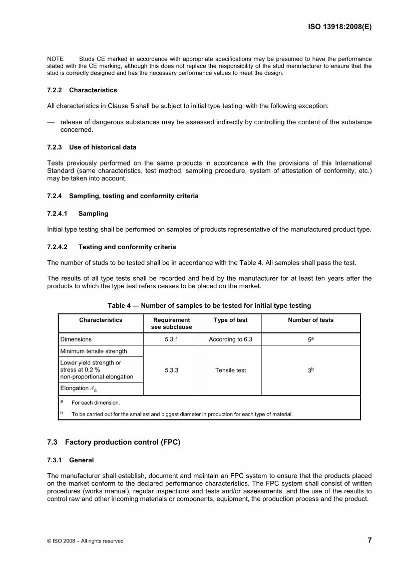
Table 4 — Number of samples to be tested for initial type testing
Characteristics Requirement see subclause
Type of test Number of tests
Dimensions 5.3.1 According to 6.3 5a
Minimum tensile strength
Lower yield strength or stress at 0,2 % non-proportional elongation
Elongation A5
5.3.3 Tensile test 3b
a For each dimension.
b To be carried out for the smallest and biggest diameter in production for each type of material.
7.3 Factory production control (FPC)
7.3.1 General
The manufacturer shall establish, document and maintain an FPC system to ensure that the products placed on the market conform to the declared performance characteristics. The FPC system shall consist of written procedures (works manual), regular inspections and tests and/or assessments, and the use of the results to control raw and other incoming materials or components, equipment, the production process and the product.

ISO 13918:2008(E)
8 © ISO 2008 – All rights reserved
An FPC system conforming with the requirements of ISO 9001, and made product-specific to the requirements of this International Standard, shall be considered to satisfy the above requirements.
The results of inspections, tests or assessments requiring action shall be recorded, as shall any action taken. The action to be taken when control values or criteria are not met shall be recorded and retained for the period specified in the manufacturer's FPC procedures.
7.3.2 Personnel
The responsibility, authority and relationship between personnel that manages, performs or verifies work affecting product conformity shall be defined. This applies in particular to personnel that needs to initiate actions preventing product non-conformities from occurring, actions in case of non-conformities and to identify and register product conformity problems.
7.3.3 Equipment
All measuring and testing equipment shall be calibrated or verified and regularly inspected according to documented procedures, frequencies and criteria.
All equipment used in the manufacturing process shall be regularly inspected and maintained to ensure that use, wear or failure does not cause inconsistency in the manufacturing process.
Inspections and maintenance shall be carried out and recorded in accordance with the manufacturer's written procedures and the records retained for the period defined in the manufacturer's FPC procedures.
7.3.4 Design process
The factory production control system shall document the various stages in the design of the products, identify the checking procedure and those individuals responsible for all stages of design.
During the design process itself, a record shall be kept of all checks, their results, and any corrective actions taken. This record shall be sufficiently detailed and accurate to demonstrate that all stages of the design phase and all checks have been carried out satisfactorily.
7.3.5 Raw materials
The specifications of all incoming raw materials shall be documented, as shall the inspection scheme for ensuring their conformity.
7.3.6 In-process control
The manufacturer shall plan and carry out production under controlled conditions.
7.3.7 Product testing and evaluation
The manufacturer shall establish procedures to ensure that the production tolerances allow for the product performances to be in conformity with the declared values derived from initial type testing.
The characteristics and the means of verification are given in the Table 5.
ISO 13918:2008(E)
© ISO 2008 – All rights reserved 9
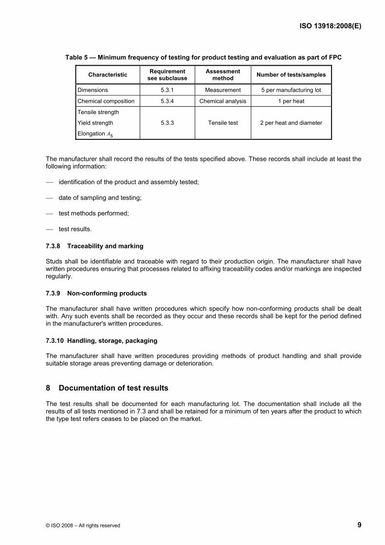
Table 5 — Minimum frequency of testing for product testing and evaluation as part of FPC
Characteristic Requirement see subclause
Assessment method Number of tests/samples
Dimensions 5.3.1 Measurement 5 per manufacturing lot
Chemical composition 5.3.4 Chemical analysis 1 per heat
Tensile strength
Yield strength
Elongation A5
5.3.3 Tensile test 2 per heat and diameter
The manufacturer shall record the results of the tests specified above. These records shall include at least the following information:
⎯ identification of the product and assembly tested;
⎯ date of sampling and testing;
⎯ test methods performed;
⎯ test results.
7.3.8 Traceability and marking
Studs shall be identifiable and traceable with regard to their production origin. The manufacturer shall have written procedures ensuring that processes related to affixing traceability codes and/or markings are inspected regularly.
7.3.9 Non-conforming products
The manufacturer shall have written procedures which specify how non-conforming products shall be dealt with. Any such events shall be recorded as they occur and these records shall be kept for the period defined in the manufacturer's written procedures.
7.3.10 Handling, storage, packaging
The manufacturer shall have written procedures providing methods of product handling and shall provide suitable storage areas preventing damage or deterioration.
8 Documentation of test results
The test results shall be documented for each manufacturing lot. The documentation shall include all the results of all tests mentioned in 7.3 and shall be retained for a minimum of ten years after the product to which the type test refers ceases to be placed on the market.

ISO 13918:2008(E)
10 © ISO 2008 – All rights reserved
9 Dimensions of studs
9.1 General
Nominal dimensions are listed in Tables 6 to 16. Divergence in outline shape, finish or dimensions shall be permitted, provided the welding area complies with the specifications of the said tables.
The length after welding, l2, is a design value. By proper control of the welding it is possible to keep variations in l2 to within ± 1 mm. Under special conditions, e.g. through-deck stud welding, l2 may be constantly different from the nominal value.
The form of the central part of the stud tip comprised inside the diameter d1/3 for stud types UD, SD (d2/3 for stud types PD, RD, ID) shall be at the manufacturer's discretion. The tip shall be at the manufacturer's discretion in the case of flux in the form of a press-fitted aluminium ball (e.g. flattened in the centre with a diameter not exceeding 0,5 d1).
The dimensions of stud collars shown in Figures 1 to 5 are guidance values and may generally be achieved in welding position PA in accordance with ISO 6947. The weld collars shown in Figures 1 to 5 are subject to variations regarding evenness and shape.
Details left unspecified shall be at the manufacturer's discretion. This shall apply to any modification of the shape of the stud outside the welding area, e.g. drillings and slots, provided the weldability is not affected.
As long as no tolerances are specified for special dimensions in this International Standard, tolerances on dimensions, form and position shall be such as to comply with product grade A as specified in ISO 4759-1.
9.2 Threaded stud (PD)
Before welding After welding
Key
1 weld collar
Figure 1 — Threaded stud (PD)

ISO 13918:2008(E)
© ISO 2008 – All rights reserved 11
Table 6 — Dimensions of threaded studs (PD) Dimensions in millimetres
d1 M6 M8 M10 M12 M16 M20 M24
d2 5,35 7,19 9,03 10,86 14,6 18,38 22,05
d3 8,5 10 12,5 15,5 19,5 24,5 30
h4 3,5 3,5 4 4,5 6 7 10
α ± 2,5° 22,5° 22,5° 22,5° 22,5° 22,5° 22,5° 22,5°
l1 ± 1 l2 + 2,2 l2 + 2,4 l2 + 2,6 l2 + 3,1 l2 + 3,9 l2 + 4,3 l2 + 5,1
l2 ymin b ymin b ymin b ymin b ymin b ymin b ymin b
15 9 — — — — — — — — — — — — —
20 9 — 9 — 9,5 — — — — — — — — —
25 9 — 9 — 9,5 — 11,5 — — — — — — —
30 9 — 9 — 9,5 — 11,5 — 13,5 — — — — —
35 — 20 9 — 9,5 — 11,5 — 13,5 — 15,5 — — —
40 — 20 9 — 9,5 — 11,5 — 13,5 — 15,5 — — —
45 — — 9 — 9,5 — 11,5 — 13,5 — 15,5 — — —
50 — — — 40 — 40 — 40 13,5 — — 35 20 —
55 — — — — — — — — — 40 — 40 — —
60 — — — — — — — — — 40 — 40 — —
65 — — — — — — — — — 40 — 40 — —
70 — — — — — — — — — — — 40 — 50
80 — — — — — — — — — — — 50 — 50
100 — — — — — 40 — 40 — 80 — 70 — 70
140 — — — — — 80 — 80 — 80 — — — —
150 — — — — — 80 — 80 — 80 — — — —
160 — — — — — 80 — 80 — 80 — — — —

ISO 13918:2008(E)
12 © ISO 2008 – All rights reserved
9.3 Threaded stud with reduced shaft (RD)
Before welding After welding
Key
1 weld collar
Figure 2 — Threaded stud with reduced shaft (RD)
Table 7 — Dimensions of threaded studs with reduced shaft (RD) for 15 mm u l2 u 100 mm Dimensions in millimetres
d1 M6 M8 M10 M12 M16 M20 M24
d2 4,7 6,2 7,9 9,5 13,2 16,5 20
d3 7 9 11,5 13,5 18 23 28
h4 2,5 2,5 3 4 5 6 7
ymin 4 4 5 6 7,5/11a 9/13a 12/15a
α ± 2,5° 22,5° 22,5° 22,5° 22,5° 22,5° 22,5° 22,5°
l1 ± 1 l2 + 2,0 l2 + 2,2 l2 + 2,4 l2 + 2,8 l2 + 3,6 l2 + 3,9 l2 + 4,7
a The dimensions after the oblique stroke shall apply if ceramic ferrules, according to the values following the oblique stroke in Table 19, are used.

ISO 13918:2008(E)
© ISO 2008 – All rights reserved 13
9.4 Unthreaded stud (UD)
Before welding After welding
Key
1 weld collar
Figure 3 — Unthreaded stud (UD)
Table 8 — Dimensions of unthreaded studs (UD) for l2 W 20 mm Dimensions in millimetres
d1 6 8 10 12 14,6 16
d3 8,5 11 13 16 18,5 21
h4 4 4 4 5 6 7
α ± 2,5° 22,5° 22,5° 22,5° 22,5° 22,5° 22,5°
l1 ± 1 l2 + 2,4 l2 + 2,6 l2 + 2,8 l2 + 3,4 l2 + 3,9 l2 + 3,9

ISO 13918:2008(E)
14 © ISO 2008 – All rights reserved
9.5 Stud with internal thread (ID)
Before welding After welding
Key
1 weld collar
Figure 4 — Stud with internal thread (ID)
Table 9 — Dimensions of studs with internal thread (ID) Dimensions in millimetres
D6 M 5 M 6 M 8 M 8 M 10 M 10 M 12
d2 10 10 12 14,6 14,6 16 18
d3 13 13 16 18,5 18,5 21 23
b 7 9 9,5 15 15 15 18
h4 4 4 5 6 6 7 7
l2 15 15 20 25 25 25 30
α ± 2,5° 22,5° 22,5° 22,5° 22,5° 22,5° 22,5° 22,5°
l1 ± 1 l2 + 2,8 l2 + 2,8 l2 + 3,4 l2 + 3,9 l2 + 3,9 l2 + 3,9 l2 + 4,2
ISO 13918:2008(E)
© ISO 2008 – All rights reserved 15
9.6 Shear connector (SD)
Before welding After welding
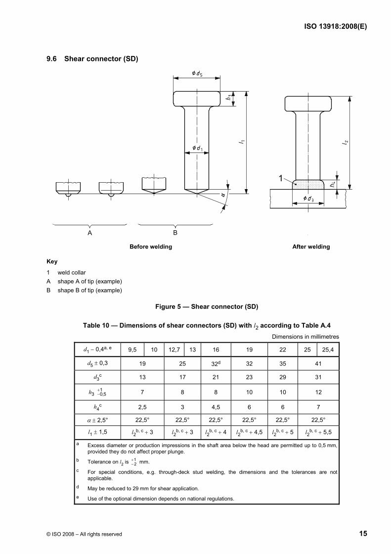
Key
1 weld collar A shape A of tip (example) B shape B of tip (example)
Figure 5 — Shear connector (SD)
Table 10 — Dimensions of shear connectors (SD) with l2 according to Table A.4 Dimensions in millimetres
d1 − 0,4a, e 9,5 10 12,7 13 16 19 22 25 25,4
d5 ± 0,3 19 25 32d 32 35 41
d3c 13 17 21 23 29 31
13 0,5h +
− 7 8 8 10 10 12
h4c 2,5 3 4,5 6 6 7
α ± 2,5° 22,5° 22,5° 22,5° 22,5° 22,5° 22,5°
l1 ± 1,5 l2b, c + 3 l2
b, c + 3 l2b, c + 4 l2
b, c + 4,5 l2b, c + 5 l2
b, c + 5,5
a Excess diameter or production impressions in the shaft area below the head are permitted up to 0,5 mm, provided they do not affect proper plunge.
b Tolerance on l2 is 12
+− mm.
c For special conditions, e.g. through-deck stud welding, the dimensions and the tolerances are not applicable.
d May be reduced to 29 mm for shear application. e Use of the optional dimension depends on national regulations.
ISO 13918:2008(E)
16 © ISO 2008 – All rights reserved
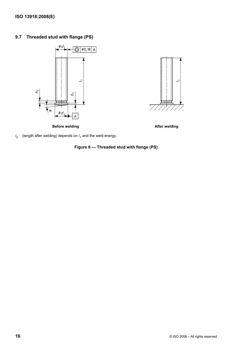
9.7 Threaded stud with flange (PS)
Before welding After welding
l2 (length after welding) depends on l1 and the weld energy.
Figure 6 — Threaded stud with flange (PS)

ISO 13918:2008(E)
© ISO 2008 – All rights reserved 17
Table 11 — Dimensions of threaded studs with flange (PS) Dimensions in millimetres
d1a l1 d2 ± 0,2 max. h5 h1 α ± 1° b
M3
6
8
10
12
16
20
4
M4
8
10
12
16
20
25
5
0,6
M5 6
M6
10
12
16
20
25
30
7
1,0
0,7 to 1,4
M8
12
16
20
25
30
35
40
9 1,5
M10
16
20
25
30
35
40
11 2,0
0,8 to 1,4
7°
a Other types of thread are subject to agreement.
b For applications using sheet thicknesses W 2 mm and welding times > 60 ms, the angle α may be increased up to 14°.

ISO 13918:2008(E)
18 © ISO 2008 – All rights reserved
9.8 Unthreaded stud (US)
Before welding After welding
l2 (length after welding) depends on l1 and the weld energy.
Figure 7 — Unthreaded stud (US)
Table 12 — Dimensions of unthreaded studs (US) Dimensions in millimetres
d1 l1 d2 ± 0,2 h1 α ± 1° a
3 4
4 5
5 6
6
8 10 12 16 20 25 7
0,7 to 1,4
7,1
8
16 20 25
9 0,8 to 1,4
7°
a For applications using sheet thicknesses W 2 mm and welding times > 60 ms, the angle α may be increased up to 14°.

ISO 13918:2008(E)
© ISO 2008 – All rights reserved 19
9.9 Stud with internal thread (IS)
Before welding After welding
l2 (length after welding) depends on l1 and the weld energy.
The depth of the hole shall be at the discretion of the manufacturer.
Figure 8 — Stud with internal thread (IS)
Table 13 — Dimensions of studs with internal thread (IS) Dimensions in millimetres
D6 l1 bmin d2 ± 0,2 d1 ± 0,1 h1 α ± 1° a
M3
10
12
16
5 6,0 5,0
5
M4
10
12
16
20 6
7,0 6,0
0,7 to 1,4
6
M5
10
12
16
20 10
7,1
M6
16
20
25
10
9,0
8,0
0,8 to 1,4
7°
a For applications using sheet thicknesses W 2 mm and welding times > 60 ms, the angle α may be increased up to 14°.

ISO 13918:2008(E)
20 © ISO 2008 – All rights reserved
9.10 Threaded stud (PT)
l2 ≈ l1 − 0,3 mm
Before welding After welding
Figure 9 — Threaded stud (PT)
Table 14 — Dimensions of threaded studs (PT) Dimensions in millimetres
d1 l1 d2 ± 0,2 d4 ± 0,08 l3 ± 0,05 max. h5 h1 α ± 1°
M3
6 8
10 12 16 20
4,5 0,60
M4
8 10 12 16 20 25
5,5 0,65
0,55 0,6
M5 6,5
M6
10 12 16 20 25 30
7,5
0,80 1,0
0,7 to 1,4
M8
12 16 20 25 30
9
0,75
0,85 1,5 0,8 to 1,4
3°

ISO 13918:2008(E)
© ISO 2008 – All rights reserved 21
9.11 Unthreaded stud (UT)
l2 ≈ l1 − 0,3 mm
Before welding After welding
Figure 10 — Unthreaded stud (UT)
Table 15 — Dimensions of unthreaded studs (UT) Dimensions in millimetres
d1 ± 0,1 l1 d2 ± 0,2 d4 ± 0,08 l3 ± 0,05 h1 α ± 1°
3 4,5 0,60
4
8 10 12 16 20 5,5 0,65
0,55
5 6,5
6
12 16 20 25 7,5
0,80
0,7 to 1,4
7,1 16 20 25
9
0,75
0,85 0,8 to 1,4
3°

ISO 13918:2008(E)
22 © ISO 2008 – All rights reserved
9.12 Stud with internal thread (IT)
l2 ≈ l1 − 0,3 mm
Before welding After welding
The depth of the hole shall be to the discretion of the manufacturer.
Figure 11 — Stud with internal thread (IT)
Table 16 — Dimensions of studs with internal thread (IT) Dimensions in millimetres
d1 ± 0,1 D6 l1 b d2 ± 0,2 d4 ± 0,08 l3 ± 0,05 h1 α ± 1°
5 M3 5 6,5
6 M4 6 7,5 0,80 0,7 to 1,4
7,1 M5
10 12 16 20 25 7,5 9
0,75
0,85 0,8 to 1,4
3°
ISO 13918:2008(E)
© ISO 2008 – All rights reserved 23
10 Dimensions of ceramic ferrules
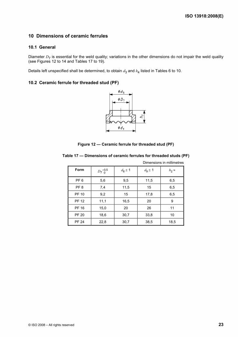
10.1 General
Diameter D7 is essential for the weld quality; variations in the other dimensions do not impair the weld quality (see Figures 12 to 14 and Tables 17 to 19).
Details left unspecified shall be determined, to obtain d3 and h4 listed in Tables 6 to 10.
10.2 Ceramic ferrule for threaded stud (PF)
Figure 12 — Ceramic ferrule for threaded stud (PF)
Table 17 — Dimensions of ceramic ferrules for threaded studs (PF) Dimensions in millimetres
Form 0,57 0D + d8 ± 1 d9 ± 1 h2 ≈
PF 6 5,6 9,5 11,5 6,5
PF 8 7,4 11,5 15 6,5
PF 10 9,2 15 17,8 6,5
PF 12 11,1 16,5 20 9
PF 16 15,0 20 26 11
PF 20 18,6 30,7 33,8 10
PF 24 22,8 30,7 38,5 18,5

ISO 13918:2008(E)
24 © ISO 2008 – All rights reserved
10.3 Ceramic ferrule for unthreaded stud and shear connector (UF)
Figure 13 — Ceramic ferrule for unthreaded stud and shear connector (UF)
Table 18 — Dimensions of ceramic ferrules for unthreaded studs and shear connectors (UF) Dimensions in millimetres
Form 0,57 0D + d8 ± 1 d9 ± 1 h2 ≈
UF 6 6,2 9,5 11,5 8,7
UF 8 8,2 11 15 8,7
UF 9,5 9,9 16,5 20,2 9,9
UF 10 10,2 15 17,8 10
UF 12 12,2 16,5 20 10,7
UF 12,7 13,1 19,9 22,2 11,1
UF 13 13,1 20 22,2/26a 11
UF 16 16,3 26 30 13
UF 19 19,4 26 30,8 16,7
UF 22 22,8 30,7 38,5 18,5
UF 25 26,0 35,5 41 21
a At the manufacturer's discretion.

ISO 13918:2008(E)
© ISO 2008 – All rights reserved 25
10.4 Ceramic ferrule for threaded stud with reduced shaft (RF)
Shallow form High form
Figure 14 — Ceramic ferrule for threaded stud with reduced shaft (RF)
Table 19 — Dimensions of ceramic ferrules for threaded studs with reduced shaft (RF) Dimensions in millimetres
Form 0,47 0D + d8 ± 1 d9 ± 1 h2 ≈
RF 6 6,2 9,5 12,2 10
RF 8 8,2 12 15,3 9
RF 10 10,2 15 18,5 11,5
RF 12 12,2 17 20 13
RF 16 16,3/14 a 20,5/26,2 a 26,5/32,5 a 15,3/8,8 a
RF 20 20,3/17,5 a 26,2/28,5 a 32 22/9 a
RF 24 24,3/21 a 26,2/30,4 b 33/36 b 25/13 a
a The dimensions after the oblique stroke shall apply if studs, according to values following the oblique stroke in Table 7, are used.
b At the manufacturer’s discretion.
11 Manufacture and finish
11.1 Threaded studs (PD), unthreaded studs (UD), threaded studs with reduced shaft (RD)
The stud tip is supplied with flux in the form of a press-fitted aluminium ball or aluminium spray coating. This may be dispensed with in the case of stainless-steel studs and diameters u 10 mm and stud welding with inert gas.
11.2 Shear connectors (SD)
The tip shape of the shear connector may be chosen by the manufacturer. The stud tip is supplied with flux in the form of a press-fitted aluminium ball or aluminium spray coating.
Completed studs shall be free of defects which can affect the application.
Cracks in the head shall be permissible, but may not exceed the value given in Figure 15.

ISO 13918:2008(E)
26 © ISO 2008 – All rights reserved
cd u 0,25 × (d5 − d1)
Key
cd depth of the crack in the head
d1 nominal diameter
d5 head diameter of headed studs
Figure 15 — Permissible head cracks for shear connectors
12 Inspection
12.1 General
The manner and extent of the inspection shall be defined by agreement when placing an order. Provided a specific material certificate (e.g. 3.1 according to EN 10204:2004 or a more significant reference) is required, the tests described in 12.2 to 12.4 shall be carried out.
12.2 Chemical analysis
Chemical analysis may be carried out on the delivery unit or on the raw material, comprising all utilized heats. The specifications of the standards specified in Table 2 shall apply.
12.3 Mechanical tests
The mechanical properties of the finished stud according to Table 2 shall be proven for every test lot, dimensions of the studs permitting. Tests shall be carried out according to 6.4.
All samples of the sample size shall meet the requirements of Table 20.
Notch impact tests may not be carried out on cold-formed material as there is a considerable variation in the results.
12.4 Sample size
The sample size shall comply with Table 20.

ISO 13918:2008(E)
© ISO 2008 – All rights reserved 27
Table 20 — Sample size
Number of units per testing lot Sample sizea
u 8 000 2
> 8 000 to 35 000 3
> 35 000 5
a All samples of the sample size shall meet the requirements of Table 2.
13 Marking
13.1 Studs
The following information shall be marked permanently on the packaging unit of the studs:
a) number of this International Standard, i.e. ISO 13918;
b) symbol of the stud (see Table 1);
c) nominal diameter and length l1 or l2 (the length used shall be marked);
d) material (see Table 2);
e) finish (if necessary, symbol in accordance with ISO 4042);
f) traceability information (see 7.3.8).
13.2 Ceramic ferrules
The following information shall be marked permanently on the packaging unit of the ceramic ferrules:
a) number of this International Standard, i.e. ISO 13918;
b) symbol of the ceramic ferrule and nominal diameter of the stud (see Tables 17, 18, 19).
14 Designation
14.1 Studs
The designation for studs shall contain the following information:
⎯ for threaded studs (PD), (PT) and threaded stud with reduced shaft (RD)
EXAMPLE 1 An M12 threaded stud (PD) made of steel of property class 4.8, with a length, l2, of 40 mm, is designated as follows:
Stud ISO 13918:2007 – PD M12×40 – 4.8
⎯ for unthreaded studs (UD), (UT)
EXAMPLE 2 An unthreaded stud (UD) made of steel of property class 4.8, with a diameter, d1, of 12 mm and a length, l2, of 40 mm, is designated as follows:
Stud ISO 13918:2007 – UD 12×40 – 4.8
ISO 13918:2008(E)
28 © ISO 2008 – All rights reserved
⎯ for shear connector (SD)
EXAMPLE 3 A shear connector type 1 (SD1) made of mild steel type 1, with a diameter, d1, of 16 mm and a length, l2, of 75 mm with shape A, is designated as follows:
Stud ISO 13918:2007 – SD1 – 16×75 – A
⎯ for threaded stud with flange (PS)
EXAMPLE 4 An M4 threaded stud with flange (PS) made of steel of property class 4.8, with a length, l2, of 20 mm, copper plated, is designated as follows:
Stud ISO 13918:2007 – PS M4×20 – 4.8 – C1E
⎯ for stud with internal thread (IT)
EXAMPLE 5 A stud with internal thread (IT) made of aluminium EN AW-AlMg3, with diameters, d1, of 5 mm, d2, of M3 and a length, l2, of 20 mm, is designated as follows:
Stud ISO 13918:2007 – IT 5×M3×20 – AlMg3
14.2 Ceramic ferrules
The designation for ferrules shall contain the following information:
EXAMPLE A ceramic ferrule type PF 10 for threaded studs is designated as follows:
Ceramic ferrule ISO 13918:2007 – PF 10

ISO 13918:2008(E)
© ISO 2008 – All rights reserved 29
Annex A (informative)
Mass of studs
See Tables A.1 to A.4.
Table A.1 — Mass of threaded studs (PD) Mass in kilograms
Massb Nominal length of stud
l2a
mm M6 M8 M10 M12 M16 M20 M24
15 2,6 — — — — — —
20 3,5 6,4 10,0 — — — —
25 4,4 8,0 12,6 18,2 — — —
30 5,3 9,6 15,1 21,8 39,9 — —
35 6,2 11,1 17,6 25,4 46,6 72,9 —
40 7,1 12,7 20,1 29,1 53,3 83,3 —
45 — 14,3 22,6 32,7 59,9 93,7 —
50 — 15,9 25,1 36,3 66,6 104,1 149,8
55 — — — — 73,2 114,5 —
60 — — — — 79,9 124,9 —
65 — — — — 86,6 135,3 —
70 — — — — — 145,7 —
75 — — — — — — 224,7
100 — — 50,2 72,7 133,2 — 299,6
140 — — 70,3 101,7 186,4 — —
150 — — 75,4 109,0 199,7 — —
160 — — 80,4 116,3 213,1 — —
a l2 is the design value. By proper control of the welding it is possible to keep variations in l2 to within ± 1 mm.
b Due to the tolerances, the values of mass are only approximate (specific weight = 7,85 kg/dm3), in kilograms per 1 000 pieces.
ISO 13918:2008(E)
30 © ISO 2008 – All rights reserved
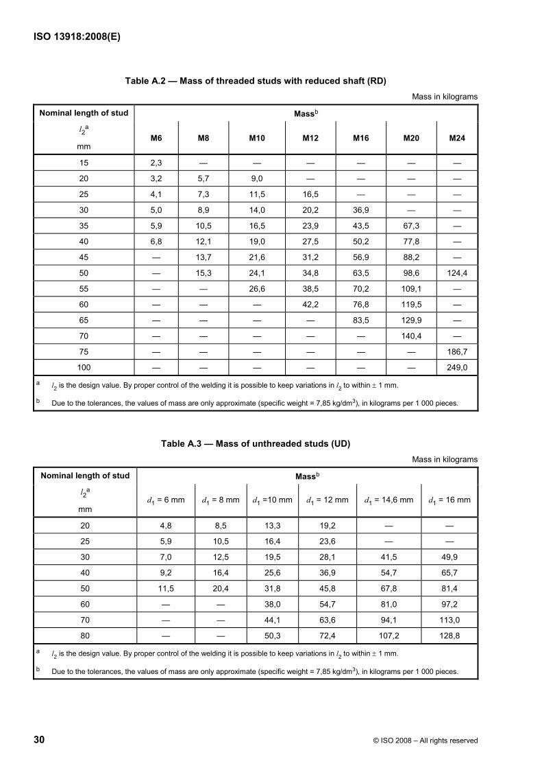
Table A.2 — Mass of threaded studs with reduced shaft (RD) Mass in kilograms
Massb Nominal length of stud
l2a
mm M6 M8 M10 M12 M16 M20 M24
15 2,3 — — — — — —
20 3,2 5,7 9,0 — — — —
25 4,1 7,3 11,5 16,5 — — —
30 5,0 8,9 14,0 20,2 36,9 — —
35 5,9 10,5 16,5 23,9 43,5 67,3 —
40 6,8 12,1 19,0 27,5 50,2 77,8 —
45 — 13,7 21,6 31,2 56,9 88,2 —
50 — 15,3 24,1 34,8 63,5 98,6 124,4
55 — — 26,6 38,5 70,2 109,1 —
60 — — — 42,2 76,8 119,5 —
65 — — — — 83,5 129,9 —
70 — — — — — 140,4 —
75 — — — — — — 186,7
100 — — — — — — 249,0
a l2 is the design value. By proper control of the welding it is possible to keep variations in l2 to within ± 1 mm.
b Due to the tolerances, the values of mass are only approximate (specific weight = 7,85 kg/dm3), in kilograms per 1 000 pieces.
Table A.3 — Mass of unthreaded studs (UD) Mass in kilograms
Massb Nominal length of stud
l2a
mm d1 = 6 mm d1 = 8 mm d1 =10 mm d1 = 12 mm d1 = 14,6 mm d1 = 16 mm
20 4,8 8,5 13,3 19,2 — —
25 5,9 10,5 16,4 23,6 — —
30 7,0 12,5 19,5 28,1 41,5 49,9
40 9,2 16,4 25,6 36,9 54,7 65,7
50 11,5 20,4 31,8 45,8 67,8 81,4
60 — — 38,0 54,7 81,0 97,2
70 — — 44,1 63,6 94,1 113,0
80 — — 50,3 72,4 107,2 128,8
a l2 is the design value. By proper control of the welding it is possible to keep variations in l2 to within ± 1 mm.
b Due to the tolerances, the values of mass are only approximate (specific weight = 7,85 kg/dm3), in kilograms per 1 000 pieces.

ISO 13918:2008(E)
© ISO 2008 – All rights reserved 31
Table A.4 — Mass of shear connectors (SD) Mass in kilograms
Massb Nominal length of stud
l2a
mm d1 = 10 mm d1 = 13 mm d1 = 16 mm d1 = 19 mm d1 = 22 mm d1 = 25 mm
50 5 8 12 16 20 —
75 6 10 16 21 28 37
100 8 13 20 27 35 47
125 9 16 24 33 43 57
150 11 18 28 38 50 66
175 12 21 32 44 58 76
200 — 23 36 49 65 85
225 — — 40 55 73 95
250 — — 44 60 80 105
275 — — — 66 88 114
300 — — — 72 95 124
325 — — — 77 102 134
350 — — — 83 110 143
a l2 is the design value. For special conditions, e.g. through-deck stud welding, l2 will be shorter.
b Due to the tolerances, the values of mass are only approximate (specific weight = 7,85 kg/dm3), in kilograms per 1 000 pieces.

ISO 13918:2008(E)
32 © ISO 2008 – All rights reserved
Bibliography
[1] EN 10025-2, Hot rolled products of structural steels — Part 2: Technical delivery conditions for non-alloy structural steels
[2] EN 10204:2004, Metallic products — Types of inspection documents
[3] ISO 724, ISO general-purpose metric screw threads — Basic dimensions
[4] ISO 9001, Quality management systems — Requirements
[5] ISO/TR 10108, Steel — Conversion of hardness values to tensile strength values
[6] ISO 15330:1999, Fasteners — Preloading test for the detection of hydrogen embrittlement — Parallel bearing surface method


ISO 13918:2008(E)
ICS 21.060.10; 25.160.10 Price based on 32 pages
© ISO 2008 – All rights reserved