international iso standard 10438-3iso-iran.ir/standards/iso/iso_10438_3_2007_,_petroleum... · iso...
TRANSCRIPT

Reference numberISO 10438-3:2007(E)
© ISO 2007
INTERNATIONAL STANDARD
ISO10438-3
Second edition2007-12-15
Petroleum, petrochemical and natural gas industries — Lubrication, shaft-sealing and control-oil systems and auxiliaries —Part 3: General-purpose oil systems
Industries du pétrole, de la pétrochimie et du gaz naturel — Systèmes de lubrification, systèmes d'étanchéité, systèmes d'huile de régulation et leurs auxiliaires —
Partie 3: Systèmes d'huile pour applications générales
Copyright International Organization for Standardization Provided by IHS under license with ISO
Not for ResaleNo reproduction or networking permitted without license from IHS
--`,,```,,,,````-`-`,,`,,`,`,,`---
ISO 10438-3:2007(E)
PDF disclaimer This PDF file may contain embedded typefaces. In accordance with Adobe's licensing policy, this file may be printed or viewed but shall not be edited unless the typefaces which are embedded are licensed to and installed on the computer performing the editing. In downloading this file, parties accept therein the responsibility of not infringing Adobe's licensing policy. The ISO Central Secretariat accepts no liability in this area.
Adobe is a trademark of Adobe Systems Incorporated.
Details of the software products used to create this PDF file can be found in the General Info relative to the file; the PDF-creation parameters were optimized for printing. Every care has been taken to ensure that the file is suitable for use by ISO member bodies. In the unlikely event that a problem relating to it is found, please inform the Central Secretariat at the address given below.
COPYRIGHT PROTECTED DOCUMENT © ISO 2007 All rights reserved. Unless otherwise specified, no part of this publication may be reproduced or utilized in any form or by any means, electronic or mechanical, including photocopying and microfilm, without permission in writing from either ISO at the address below or ISO's member body in the country of the requester.
ISO copyright office Case postale 56 • CH-1211 Geneva 20 Tel. + 41 22 749 01 11 Fax + 41 22 749 09 47 E-mail [email protected] Web www.iso.org
Published in Switzerland
ii © ISO 2007 – All rights reserved
Copyright International Organization for Standardization Provided by IHS under license with ISO
Not for ResaleNo reproduction or networking permitted without license from IHS
--`,,```,,,,````-`-`,,`,,`,`,,`---
ISO 10438-3:2007(E)
© ISO 2007 – All rights reserved iii
Contents Page
Foreword............................................................................................................................................................ iv Introduction ........................................................................................................................................................ v 1 Scope ..................................................................................................................................................... 1 2 Normative references ........................................................................................................................... 1 3 Terms, abbreviated terms and definitions ......................................................................................... 2 4 General................................................................................................................................................... 2 4.1 Basic design.......................................................................................................................................... 2 4.2 General................................................................................................................................................... 4 4.3 Baseplates ............................................................................................................................................. 5 4.4 Oil reservoirs......................................................................................................................................... 6 4.5 Pumps and pump drivers..................................................................................................................... 9 4.6 Coolers................................................................................................................................................. 13 4.7 Filters ................................................................................................................................................... 16 4.8 Transfer valves.................................................................................................................................... 18 4.9 Lube-oil rundown tanks ..................................................................................................................... 18 5 Piping ................................................................................................................................................... 19 5.1 General................................................................................................................................................. 19 5.2 Oil piping ............................................................................................................................................. 19 5.3 Instrument piping................................................................................................................................ 19 5.4 Water piping ........................................................................................................................................ 19 6 Instrumentation and electrical systems ........................................................................................... 19 7 Inspection, testing and preparation for shipment........................................................................... 20 7.1 General................................................................................................................................................. 20 7.2 Inspection ............................................................................................................................................ 20 7.3 Testing ................................................................................................................................................. 20 7.4 Preparation for shipment ................................................................................................................... 22 8 Vendor's data ...................................................................................................................................... 22 8.1 General................................................................................................................................................. 22 8.2 Proposals............................................................................................................................................. 22 Annex A (informative) Datasheets .................................................................................................................. 23 Annex B (informative) Piping and instrument diagrams .............................................................................. 24 Annex C (informative) Inspector's checklist.................................................................................................. 29 Annex D (informative) Guidance to system reliability .................................................................................. 32 Bibliography ..................................................................................................................................................... 37
Copyright International Organization for Standardization Provided by IHS under license with ISO
Not for ResaleNo reproduction or networking permitted without license from IHS
--`,,```,,,,````-`-`,,`,,`,`,,`---

ISO 10438-3:2007(E)
iv © ISO 2007 – All rights reserved
Foreword
ISO (the International Organization for Standardization) is a worldwide federation of national standards bodies (ISO member bodies). The work of preparing International Standards is normally carried out through ISO technical committees. Each member body interested in a subject for which a technical committee has been established has the right to be represented on that committee. International organizations, governmental and non-governmental, in liaison with ISO, also take part in the work. ISO collaborates closely with the International Electrotechnical Commission (IEC) on all matters of electrotechnical standardization.
International Standards are drafted in accordance with the rules given in the ISO/IEC Directives, Part 2.
The main task of technical committees is to prepare International Standards. Draft International Standards adopted by the technical committees are circulated to the member bodies for voting. Publication as an International Standard requires approval by at least 75 % of the member bodies casting a vote.
Attention is drawn to the possibility that some of the elements of this document may be the subject of patent rights. ISO shall not be held responsible for identifying any or all such patent rights.
ISO 10438-3 was prepared by Technical Committee ISO/TC 67, Materials, equipment and offshore structures for petroleum, petrochemical and natural gas industries, Subcommittee SC 6, Processing equipment and systems.
This second edition cancels and replaces the first edition (ISO 10438-3:2003), which has been technically revised.
ISO 10438 consists of the following parts, under the general title Petroleum, petrochemical and natural gas industries — Lubrication, shaft-sealing and control-oil systems and auxiliaries:
⎯ Part 1: General requirements
⎯ Part 2: Special-purpose oil systems
⎯ Part 3: General-purpose oil systems
⎯ Part 4: Self-acting gas seal support systems
Copyright International Organization for Standardization Provided by IHS under license with ISO
Not for ResaleNo reproduction or networking permitted without license from IHS
--`,,```,,,,````-`-`,,`,,`,`,,`---

ISO 10438-3:2007(E)
© ISO 2007 – All rights reserved v
Introduction
This International Standard was developed jointly with API 614, 5th edition. ISO 10438 is divided into four parts corresponding to the four chapters of API 614.
Users of this part of ISO 10438 should be aware that further or differing requirements might be needed for individual applications. This part of ISO 10438 is not intended to inhibit a vendor from offering, or the purchaser from accepting, alternative equipment or engineering solutions for the individual application. This may be particularly appropriate where there is innovative or developing technology. Where an alternative is offered, the vendor should identify any variations from this part of ISO 10438 and provide details. This part of ISO 10438 is to be used in conjunction with 10438-1.
This part of ISO 10438 requires the purchaser to specify certain details and features.
A bullet (•) at the beginning of a clause or subclause indicates that either a decision is required or further information is to be provided by the purchaser. This information should be indicated on the datasheet(s); otherwise it should be stated in the quotation request or in the order.
In this International Standard, US Customary (USC) units are included in brackets for information.
Copyright International Organization for Standardization Provided by IHS under license with ISO
Not for ResaleNo reproduction or networking permitted without license from IHS
--`,,```,,,,````-`-`,,`,,`,`,,`---

Copyright International Organization for Standardization Provided by IHS under license with ISO
Not for ResaleNo reproduction or networking permitted without license from IHS
--`,,```,,,,````-`-`,,`,,`,`,,`---
INTERNATIONAL STANDARD ISO 10438-3:2007(E)
© ISO 2007 – All rights reserved 1
Petroleum, petrochemical and natural gas industries — Lubrication, shaft-sealing and control-oil systems and auxiliaries —
Part 3: General-purpose oil systems
1 Scope
This part of ISO 10438, in conjunction with ISO 10438-1, specifies requirements for oil systems for general-purpose applications. These oil systems can provide lubrication oil, but not seal oil and can serve equipment such as compressors, gears, pumps and drivers.
NOTE The term “general-purpose” is defined in ISO 10438-1.
2 Normative references
The following referenced documents are indispensable for the application of this document. For dated references, only the edition cited applies. For undated references, the latest edition of the referenced document (including any amendments) applies.
ISO 10438-1:2007, Petroleum, petrochemical and natural gas industries — Lubrication, shaft-sealing and control-oil systems and auxiliaries — Part 1: General requirements
ISO 10438-2:2007, Petroleum, petrochemical and natural gas industries — Lubrication, shaft-sealing and control-oil systems and auxiliaries — Part 2: Special-purpose oil systems
ISO 13706:2005, Petroleum, petrochemical and natural gas industries — Air-cooled heat exchangers
ISO 13709, Centrifugal pumps for petroleum, petrochemical and natural gas industries
ISO 15649:2001, Petroleum and natural gas industries — Piping
ISO 16889, Hydraulic fluid power — Filters — Multi-pass method for evaluating filtration performance of a filter element 1)
API RP 686, Machinery Installation and Installation Design
IEC 60034 (all parts), Rotating electrical machines
TEMA, Standards of the Tubular Exchanger Manufacturers Association
NEMA MG1, Motors and Generators
1) To be published. (Revision of ISO 16889:1999)
Copyright International Organization for Standardization Provided by IHS under license with ISO
Not for ResaleNo reproduction or networking permitted without license from IHS
--`,,```,,,,````-`-`,,`,,`,`,,`---

ISO 10438-3:2007(E)
2 © ISO 2007 – All rights reserved
3 Terms, abbreviated terms and definitions
For the purposes of this document, the terms, definitions and abbreviated terms given in ISO 10438-1 apply.
4 General
4.1 Basic design
4.1.1 This part of ISO 10438 covers general-purpose oil systems. Typical datasheets for general-purpose oil systems are in Annex A. Typical piping and instrument diagrams for general-purpose oil systems are in Annex B. Typical inspector checklists for general-purpose oil systems are in Annex C. General-purpose (GP) oil systems are divided into classes and are defined by a coding system that defines the major components supplied (see Table 1). The user shall choose the applicable class and code based upon the required minimum reliability targets for the equipment train. Various API standards have supplied minimum recommended systems as indicated in Table 2 for their equipment. Annex D is supplied as a reference to provide guidance on the selection of a system.
Table 1 — General-purpose oil system class types with standard configuration options
Equipment Class I Class II Class III
Pump configuration Shaft-driven main pump only Shaft-driven main pump and motor auxiliary pump
Motor main and motor auxiliary pump
Positive displacement P0 P0 P0
Centrifugal N/A N/A P1
Reservoir part of equipment (i.e. gear case) R0 R0 R0
External stainless reservoir R1 R1 R1
Stainless pipe Default Default Default
No reservoir heater included H0 H0 H0
Reservoir heater H1 H1 H1
Baseplate part of equipment BP0 BP0 BP0
Stand-alone console, reservoir mounted
(No baseplate) BP1 BP1 BP1
Stand-alone console with full baseplate BP2 BP2 BP2
Single cooler and single filter C1F1 C1F1 C1F1
Single cooler and dual filter C1F2 C1F2 C1F2
Dual cooler and single filter C2F1 C2F1 C2F1
Dual cooler and dual filter C2F2 C2F2 C2F2
Shell-and-tube cooler(s) C0 C0 C0
Plate-and-frame cooler(s) C1 C1 C1
Fin/Fan cooler C2 C2 C2
Combined plv/pcv
(not applicable to centrifugal pumps)
PV0 PV0 PV0
Copyright International Organization for Standardization Provided by IHS under license with ISO
Not for ResaleNo reproduction or networking permitted without license from IHS
--`,,```,,,,````-`-`,,`,,`,`,,`---

ISO 10438-3:2007(E)
© ISO 2007 – All rights reserved 3
Table 1 (continued)
Equipment Class I Class II Class III
Separate PCV PV1 PV1 PV1
No thermostatic valve included TV0 TV0 TV0
Thermostatic valve TV1 TV1 TV1
No block-and-bypass valves included BB0 BB0 BB0
Block-and-bypass valves around PCV BB1 BB1 BB1
EXAMPLE 1 General-purpose system designations: Class I-P0-R1-H1-BP1-C1F2-C0-PV0-TV0-BB0
Shaft-driven main pump
Positive-displacement pump
External stainless steel reservoir
Reservoir heater included
Stand-alone console reservoir mounted equipment (no baseplate)
Single cooler and dual filters
Shell and tube cooler type
Combined PLV and PCV
No thermostatic valve
No block and bypass valves
EXAMPLE 2 General-purpose system designations: Class III-P0-R1-H1-BP2-C2F2-C0-PV1-TV1-BB1
Motor-driven main and motor-driven auxiliary pump
Positive-displacement pumps
External stainless steel reservoir
Reservoir heater included
Stand-alone console with full baseplate
Dual coolers and dual filters
Shell and tube cooler type
Separate PLV and PCV
Thermostatic valve
Block and bypass valves
Copyright International Organization for Standardization Provided by IHS under license with ISO
Not for ResaleNo reproduction or networking permitted without license from IHS
--`,,```,,,,````-`-`,,`,,`,`,,`---
ISO 10438-3:2007(E)
4 © ISO 2007 – All rights reserved
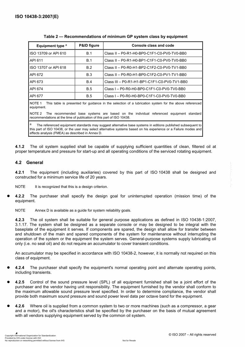
Table 2 — Recommendations of minimum GP system class by equipment
Equipment type a P&ID figure Console class and code
ISO 13709 or API 610 B.1 Class II – P0-R1-H0-BP0-C1F1-C0-PV0-TV0-BB0
API 611 B.1 Class II – P0-R1-H0-BP1-C1F1-C0-PV0-TV0-BB0
ISO 13707 or API 618 B.2 Class II – P0-R0-H1-BP2-C1F2-C0-PV0-TV1-BB0
API 672 B.3 Class II – P0-R0-H1-BP0-C1F2-C0-PV1-TV1-BB0
API 673 B.4 Class III – P0-R1-H1-BP1-C1F1-C0-PV0-TV1-BB0
API 674 B.5 Class I – P0-R0-H0-BP0-C1F1-C0-PV0-TV0-BB0
API 677 B.5 Class I – P0-R0-H0-BP0-C1F1-C0-PV0-TV0-BB0
NOTE 1 This table is presented for guidance in the selection of a lubrication system for the above referenced equipment.
NOTE 2 The recommended base systems are based on the individual referenced equipment standard recommendations at the time of publication of this part of ISO 10438.
a The referenced equipment standards may suggest alternative base systems in editions published subsequent to this part of ISO 10438, or the user may select alternative systems based on his experience or a Failure modes and effects analysis (FMEA) as described in Annex D.
4.1.2 The oil system supplied shall be capable of supplying sufficient quantities of clean, filtered oil at proper temperature and pressure for start-up and all operating conditions of the serviced rotating equipment.
4.2 General
4.2.1 The equipment (including auxiliaries) covered by this part of ISO 10438 shall be designed and constructed for a minimum service life of 20 years.
NOTE It is recognized that this is a design criterion.
4.2.2 The purchaser shall specify the design goal for uninterrupted operation (mission time) of the equipment.
NOTE Annex D is available as a guide for system reliability goals.
4.2.3 The oil system shall be suitable for general purpose applications as defined in ISO 10438-1:2007, 3.1.17. The system shall be designed as a separate console or may be designed to be integral with the baseplate of the equipment it serves. If components are spared, the design shall allow for transfer between and shutdown of the main and spared components of the system for maintenance without interrupting the operation of the system or the equipment the system serves. General-purpose systems supply lubricating oil only (i.e. no seal oil) and do not require an accumulator to cover transient conditions.
An accumulator may be specified in accordance with ISO 10438-2, however, it is normally not required on this class of equipment.
4.2.4 The purchaser shall specify the equipment's normal operating point and alternate operating points, including transients.
4.2.5 Control of the sound pressure level (SPL) of all equipment furnished shall be a joint effort of the purchaser and the vendor having unit responsibility. The equipment furnished by the vendor shall conform to the maximum allowable sound pressure level specified. In order to determine compliance, the vendor shall provide both maximum sound pressure and sound power level data per octave band for the equipment.
4.2.6 Where oil is supplied from a common system to two or more machines (such as a compressor, a gear and a motor), the oil's characteristics shall be specified by the purchaser on the basis of mutual agreement with all vendors supplying equipment served by the common oil system.
Copyright International Organization for Standardization Provided by IHS under license with ISO
Not for ResaleNo reproduction or networking permitted without license from IHS
--`,,```,,,,````-`-`,,`,,`,`,,`---

ISO 10438-3:2007(E)
© ISO 2007 – All rights reserved 5
4.2.7 The system shall be designed to supply oil to all equipment specified.
4.2.8 Recycled oil originating upstream of the filters is preferred and is required when there is a possibility of an explosive mixture in the reservoir.
NOTE This is to minimize the potential for generation of static electricity (or a static charge) that can result when filtered oil bypasses the equipment and is recycled directly to the reservoir.
4.2.9 If specified, the arrangement of the equipment, including piping and auxiliaries, shall be developed jointly by the purchaser and the vendor. The arrangement shall provide adequate clearance areas and safe access for operation and maintenance.
NOTE For some pre-engineered general purpose oil systems, purchaser input might be impractical.
4.2.10 If specified, minimum defined requirements for clearance around and access to components (especially clearance around and access to coolers, filters and hand valves) shall be incorporated as design requirements.
4.2.11 If specified, pumps, filters, strainers, coolers, traps, valves and all other components that retain oil under pressure and are external to the reservoir shall be made of steel.
4.2.12 Unless otherwise specified, pumps may be submerged in the reservoir and these may be made of cast iron.
4.2.13 If specified, valved vents, drains and piping shall be furnished to permit draining, cleaning and refilling of idle components while the equipment is in operation.
4.2.14 Unless otherwise specified, coolers, filters, overhead oil tanks, drain traps, accumulators and other pressure vessels shall be in accordance with the specified pressure design code. If specified by the purchaser, vessels shall be code stamped.
NOTE 1 Code stamping might not be applicable for pressure design codes other than ASME.
NOTE 2 Local jurisdictions can require a code stamp.
NOTE 3 Code stamping can require additional inspection over the life of the equipment.
4.2.15 The vendor shall advise the purchaser of, and both parties shall mutually agree upon, any special provisions that are necessary to ensure that an adequate back-up supply of lube oil is maintained in the event of complete failure of the primary lube-oil supply system. These provisions may include standby pumps, rundown tanks and special arrangements for equipment safety and protection when the equipment decelerates. Provisions shall be adequate for coast-down time and cool-off time, as applicable. The purchaser and the vendor shall mutually agree on the system and its components.
4.2.16 Block valves that interrupt the oil flow to the equipment shall not be installed in oil supply lines downstream of the filters unless the block valves are part of a component block and bypass arrangement.
4.2.17 When components that can require later removal for maintenance are installed using screwed connections, the connecting piping shall be provided with flanges such that the component can be removed without requiring cutting pipe or major disassembly of the unit.
4.3 Baseplates
4.3.1 The major components (pumps, filters, coolers and reservoir) shall be mounted directly on structural steel as a separate console or integrated with the equipment base.
NOTE Reference can be made to the baseplate section of the lubricated equipment specification for baseplate requirements when the console is integrated into the equipment base.
Copyright International Organization for Standardization Provided by IHS under license with ISO
Not for ResaleNo reproduction or networking permitted without license from IHS
--`,,```,,,,````-`-`,,`,,`,`,,`---
ISO 10438-3:2007(E)
6 © ISO 2007 – All rights reserved
4.3.2 Unless otherwise specified, package baseplates shall be of the drain-gutter type with one or more drain connections at least DN 40 (NPS 1 1/2). Baseplates, mounted components and decking shall be arranged and installed to ensure drainage and avoid the retention of liquid. Sloping of the decking is not required.
4.3.3 If specified, sloped decking shall be furnished.
4.3.4 The baseplate shall be provided with lifting lugs for at least a four-point lift or other suitable means. The baseplate shall be designed so that after the components and all piping mounted on it are drained of oil, the package can be lifted without permanently distorting or otherwise damaging either the baseplate or any component mounted on it.
4.3.5 If specified, metal decking covering all walk and work areas shall be provided on the top of the baseplate. If furnished, metal decking shall be non-skid.
NOTE Decking might not be required when the grout pour is used to create a walking surface.
4.3.6 If specified, baseplates shall be suitable for installation in accordance with API RP 686. Unless otherwise specified, all baseplates shall be provided with at least one opening or hole in each bulkhead section through which grout can be poured and vented. Each opening shall have a clear area of no less than 125 cm2 (20 in2) and no dimension less than 100 mm (4 in), and each shall permit filling and venting of the entire cavity with grout under the baseplate without creating air pockets. Each hole into which the grout is poured shall be accessible: no component or piping shall be disturbed and no tripping hazards in walk and work areas shall be created. Vent holes at least 13 mm (1/2 in) in diameter shall be provided for each bulkhead compartment. Each grout hole shall also be provided with steel curbing 13 mm (1/2 in) high to prevent accumulated oil or water from entering the grout. Vent holes shall be provided without curbing.
4.3.7 If specified, the baseplate shall be suitable for column mounting (that is, of sufficient rigidity to be supported at specified points) without continuous grouting under structural members. The baseplate design shall be mutually agreed upon by the purchaser and the vendor.
4.3.8 The bottom of the baseplate between structural members shall be open. When the baseplate is installed on a concrete foundation and grouted as specified in 4.3.6, accessibility for grouting under all load-carrying structural members shall be provided.
4.3.9 Levelling screws shall be provided in the proximity of each hold-down bolt.
4.4 Oil reservoirs
4.4.1 General
Reservoirs shall be separate or combined with the equipment baseplate and be rigid enough to prevent sagging and vibration. Components bolted to the reservoir shall be mounted on pads; no bolt holes shall extend into the reservoir.
4.4.2 Protection from dirt and water
Reservoirs shall be sealed to prevent dirt and water from entering. Top-surface openings shall be raised at least 6 mm (1/4 in) and shall have a gasket. When pumps, coolers or filters are mounted on top of the reservoir, the reservoir top may be provided with a drain rim or gutter and one or more drain connections.
NOTE For installations on an existing equipment base, a drain rim or gutter might not be required on the reservoir.
4.4.3 Oil connections and internal piping
4.4.3.1 All oil return flow streams shall be hydraulically located as far away from the pump suction connections as possible.
Copyright International Organization for Standardization Provided by IHS under license with ISO
Not for ResaleNo reproduction or networking permitted without license from IHS
--`,,```,,,,````-`-`,,`,,`,`,,`---
ISO 10438-3:2007(E)
© ISO 2007 – All rights reserved 7
NOTE The use of the term “hydraulically located as far away” is intended to convey the concept that return flow streams can be directed by internal piping or baffling to avoid disturbing the oil flow at pump inlets. This internal piping or baffling can be used in lieu of external connections physically located such a distance from the pump suctions that they avoid disturbing the oil flow at the pump inlets.
4.4.3.2 All atmospheric oil return connections (including fill connections) shall be located above the maximum operating level and shall transport oil (via open-top stilling tubes or degassing trays) as shown in ISO 10438-2:2007, Figure B.24. Stilling tubes shall have bottom baffles.
4.4.3.3 Pump suction connections shall be located at least 50 mm (2 in) above the reservoir bottom.
4.4.3.4 Reservoir pipe connections 40 mm (1 1/2 in) and larger shall be flanged.
4.4.4 Manways and drains
4.4.4.1 Reservoirs shall be furnished with a valved and blind-flanged or plugged-drain connection.
4.4.4.2 If specified, to ensure complete drainage, the bottom of each reservoir shall be sloped to a low point drain.
4.4.4.3 If specified, a drain connection (with a valve and a blind flange) at least 50 mm (2 in) in diameter shall be provided.
4.4.4.4 Reservoirs shall be provided with unobstructed access for direct interior visual inspection and cleaning. Manways, if required, shall be at least 600 mm × 600 mm in diameter (24 in × 24 in). If manway-sized access is not required for inspection or cleaning, a minimum 150 mm × 150 mm (6 in × 6 in) port or ports shall be provided.
4.4.5 Features and appendages
The oil reservoir shall have the following features and appendages:
a) capacity to settle moisture and foreign matter adequately and to provide allowance for rundown from the entire system;
b) provisions to eliminate air and minimize migration of foreign matter to each pump suction;
c) reservoir-level indicator, such as a dipstick, level gauge, or bulls eye;
d) if specified, an oil level glass arranged to cover the span from at least 25 mm (1 in) above the rundown level to 50 mm (2 in) below the pump suction-loss level. The oil level glass shall be located as far away as possible from the oil return lines and be visible from the perimeter of the unit. The maximum and minimum operating levels, rundown level and suction-loss level shall be indicated on the glass. If more than one level glass is provided, they shall be offset. The top glass shall be of the weld pad type;
e) weatherproof, corrosion-resistant filter-breather cap at least 50 mm (2 in) in diameter with filtration rating of 10 µm beta 10 or better shall be provided (this connection may also be used as a fill opening);
f) if specified, a fill opening at least 50 mm (2 in) in diameter that automatically closes (normally held shut by a spring) and is equipped with a stainless steel fine-mesh strainer basket that has an open area equal to 200 % of the internal pipe area;
g) internal baffles that are not gas-tight;
h) individual, non-pressurized reservoir return lines that shall enter the reservoir above the maximum operating level (see ISO 10438-1:2007, Annex F).
Copyright International Organization for Standardization Provided by IHS under license with ISO
Not for ResaleNo reproduction or networking permitted without license from IHS
--`,,```,,,,````-`-`,,`,,`,`,,`---

ISO 10438-3:2007(E)
8 © ISO 2007 – All rights reserved
4.4.6 Capacity and configurations
4.4.6.1 If specified, a low-level alarm that actuates at the minimum operating level shall be provided.
4.4.6.2 The criteria for sizing a reservoir are given in a) and b) below.
NOTE Refer to ISO 10438-1:2007, Annex F.
a) The working capacity between the minimum operating level (key item 3 in ISO 10438-1:2007, Figure F.1) and the suction-loss level (key item 4 in ISO 10438-1:2007, Figure F.1) shall be sufficient for at least 3 min of normal flow.
b) The rundown capacity shall allow for all of the oil contained in all of the components, bearings housings, rundown tanks, control elements and vendor-furnished piping that drain back to the reservoir. The rundown capacity shall also allow for at least an additional 10 % of these volumes for the purchaser's interconnecting piping.
NOTE Rundown can cause some backup in the drain lines entering the reservoir.
4.4.7 Heating
If specified, an electric heater shall be furnished in accordance with the following.
a) If an electric heater is specified, a thermostatically controlled, removable electric immersion heating element shall be provided for heating the charge capacity of oil before start-up in cold weather. The device shall have the capacity to heat the oil in the reservoir from the specified minimum site ambient temperature to the manufacturer's required start-up temperature within 12 h. Heater elements shall be sheathed in austenitic stainless steel or incoloy 2); copper or copper-bearing materials shall not contact the oil. A level interlock device shall be furnished.
Electric immersion heaters should be level interlocked by the purchaser to be de-energized when the oil level drops below the minimum operating level.
For heating the lube oil to minimum starting temperature, many factors, including lube pump start-up minimum oil temperature, equipment minimum oil temperature, circulating heat loss, etc., shall be considered. Many of these factors are the responsibility of the installing contractor and should be coordinated with the console designer. Insulation, location and heat-tracing requirements shall be considerations of the installation.
b) Direct-contact electric heaters shall have a maximum watt density of 2,32 W/cm2 (15 W/in2).
c) If specified, the heater shall be installed in a manner that allows the heater(s) to be removed during operation.
d) The hot section of the heater element shall be located a minimum of 50 mm (2 in) below the minimum operating level.
4.4.8 Provision for insulation
If specified, reservoirs shall be fitted with insulation clips. The purchaser shall furnish and install the insulation.
2) Incoloy is an example of a suitable product available commercially. This information is given for the convenience of users of this part of ISO 10438 and does not constitute an endorsement by ISO of this product.
Copyright International Organization for Standardization Provided by IHS under license with ISO
Not for ResaleNo reproduction or networking permitted without license from IHS
--`,,```,,,,````-`-`,,`,,`,`,,`---

ISO 10438-3:2007(E)
© ISO 2007 – All rights reserved 9
4.4.9 Plugged connections
If specified, each reservoir shall be provided with one threaded and plugged connection above the rundown oil level of at least DN 25 (NPS 1). This connection may be used for such services as purge gas, makeup oil supply and oil conditioner return.
4.4.10 Special features
4.4.10.1 If specified, a clearly accessible ladder with extended handrails and non-skid working surface shall be provided.
4.4.10.2 If specified, handrails around the perimeter of the reservoir top shall be provided.
4.4.10.3 If specified, non-skid surface decking shall be provided on the top of the reservoir.
4.4.10.4 For equipment mounted on the reservoir, the reservoir shall provide sufficient structural stiffness to properly support the equipment.
4.4.10.5 If the reservoir top is used as a personnel access area, it shall be designed to withstand a live load of 1 100 N (250 lbf) without permanent distortion.
4.4.11 Materials
4.4.11.1 Unless otherwise agreed upon between the purchaser and the vendor, reservoirs and all appendages (except ladders and handrails) welded to reservoirs shall be fabricated from austenitic stainless steel.
4.4.11.2 Reservoir nozzle connections shall be as specified in the piping section for oil service. (See Clause 5.)
4.4.11.3 Where reservoirs are integral with equipment or equipment baseplates, and where stainless steel inserts or cladding is not practical, coated carbon steel is acceptable upon purchaser approval.
NOTE Certain equipment, such as reciprocating compressors or gearboxes, that use crankcases or casings as reservoirs might be available only in alternate materials, such as cast iron.
4.4.12 Grounding
The reservoir shall be grounded either by grounding clips attached to the reservoir (for free-standing reservoirs) or through the attached base structure. In either case, two grounding clips or pads diagonally opposed to each other are required. The pads shall accommodate a 13 mm (1/2 in UNC) bolt.
4.5 Pumps and pump drivers
4.5.1 The oil system shall include an oil pump suitable for continuous operation. The purchaser shall specify whether centrifugal or rotary pumps shall be used. If specified, pumps shall conform to ISO 13709 or ASME B73.2 or ASME B73.3 for the centrifugal pumps and to API STD 676 for rotary pumps.
NOTE For the purposes of this provision, API STD 610 is equivalent to ISO 13709.
4.5.2 Each pump shall be driven separately.
4.5.3 Unless otherwise specified, the main oil pump (unless it is shaft-driven) shall be motor-driven.
When primary and standby pumps are motor-driven, it is recommended that the purchaser supply electric feeds from independent sources.
Copyright International Organization for Standardization Provided by IHS under license with ISO
Not for ResaleNo reproduction or networking permitted without license from IHS
--`,,```,,,,````-`-`,,`,,`,`,,`---
ISO 10438-3:2007(E)
10 © ISO 2007 – All rights reserved
4.5.4 If specified, or required by the lubricated equipment supplier, an electric-motor-driven standby pump shall be provided for start-up and/or main-pump failure backup.
NOTE Standby pumps are not always required. Some equipment, such as equipment utilizing ring-oiled bearing lubrication, might not require pre-priming and use of a standby pump.
4.5.5 Motors shall comply with the area classification and shall comply with NEMA MG1 or applicable part(s) of IEC 60034.
“C-flanged” motors may be used for motors equal to or below 7,5 kW (10 hp).
4.5.6 The minimum criteria given in a) through c) shall be used when sizing pumps.
a) In all cases, pumps shall be sized to deliver the required capacity when pumping lube oil at the highest temperature and the corresponding minimum viscosity (see 4.5.8).
b) Each pump (main or standby) shall be capable of supplying the normal oil flow required by the equipment plus 20 % of the normal oil flow.
c) Rotary pumps shall be capable of passing the total flow, as established in b), at the pressure-limiting valve set pressure while not exceeding 90 % of the pump manufacturer's maximum differential pressure rating at the minimum operating viscosity. The pump shall also be capable of operating continuously at the normal flow, pressure-limiting valve set pressure and minimum operating viscosity.
NOTE This selection criterion is required to avoid pump rotor contact during operation under extreme conditions.
4.5.7 The normal operating capacity of the centrifugal pumps shall be within 50 % to 110 % of their best efficiency point. From their normal operating point to shutoff, centrifugal pumps shall have a continuous rise in head of at least 5 % and, with the installation of a new impeller, shall be capable of a future increase in head of at least 10 %.
4.5.8 Pump drivers shall be sized in accordance with a) or b) as applicable.
a) Centrifugal pumps shall deliver the specified system pressure across the pump's stable flow range when the temperature of the pumped oil is 10 °C (50 °F).
b) Rotary pumps shall be capable of operating at the specified pump pressure-limiting valve setting (including accumulation) when the temperature of the pumped oil is 10 °C (50 °F).
4.5.9 Check valves shall be provided on each pump discharge to prevent the flow of oil backwards through a standby or idling pump.
Shaft-driven pumps may use a drilled check valve or an orificed line to prime the pump (see ISO 10438-1:2007, 4.5.6).
4.5.10 For rotary-pump systems, the vendor shall furnish external pressure-limiting valves that shall be installed on the pump or in the piping supplied by the vendor. This valve shall not be used for pressure control. Pressure-limiting valve settings, including an allowance for accumulation, shall be determined after all of the possible equipment and component failures are considered. The settings shall protect the oil-system components and piping. Fully accumulated pressure cannot exceed 110 % of the system design pressure.
4.5.11 Oil-pressure limiting valves (PLV) shall be pressure-modulating devices (as opposed to snap-acting or pop-type safety relief valves) with a pressure increase proportional to flow above the valve cracking pressure (that is, the pressure at which the valve begins to open). These devices shall be mounted external to the reservoir and shall operate smoothly, without chattering and without causing a drop in supply pressure to the equipment. Pressure-limiting valve piping shall be sized for the full flow of each pump; the valves shall not chatter and the piping shall not vibrate. The minimum pressure-limiting valve cracking pressure shall be 10 % or 170 kPa (1,7 bar; 25 psi) higher than the highest required operating pressure, including operation at 10 °C (50 °F), whichever is greater. To avoid unnecessary delay in opening, pressure-limiting valve takeoff points shall be located as close to the oil pump discharge as possible. Pressure-limiting valves shall not be used for continuous pressure regulation.
Copyright International Organization for Standardization Provided by IHS under license with ISO
Not for ResaleNo reproduction or networking permitted without license from IHS
--`,,```,,,,````-`-`,,`,,`,`,,`---

ISO 10438-3:2007(E)
© ISO 2007 – All rights reserved 11
4.5.12 The oil system shall be provided with pressure-regulating devices that prevent fluctuation of the oil pressure to the equipment serviced by the lube-oil console when both the main and the standby pump are in operation or when either the main or the standby pump is in operation and the other pump is started, brought up to operating speed or stopped. Each device shall have an adequate response time and shall operate smoothly without hunting, chattering or producing pressure or flow transients that can cause a mechanical problem or shutdown of the equipment [see 7.3.3.7 e)]. These pressure-regulating devices shall be located so that an excessive rise in oil temperature resulting from a recirculation of uncooled oil is avoided (see, for example, ISO 10438-2:2007, Figure B.11). Where non-pressure-regulating PLV's are used, the pressure-regulating valve shall be selected such that the PLVs do not lift during two-pump operation.
NOTE Additional supply pressure is acceptable during two-pump operation as long as this over-pressurization is compatible with the equipment serviced by the lube oil-console.
4.5.13 All pumps (except shaft-driven pumps) shall be installed with flooded suctions to ensure self-priming and shall be installed with suction-block valves (unless the pumps are inside the reservoir) and with discharge-block and check valves. Vertically mounted pumps shall be continuously vented to assure the entire pump remains flooded. Shaft-driven pumps shall have adequate provision for priming and be of positive displacement design. Suction piping shall be continuously vented or arranged to avoid pockets in which air can accumulate or become trapped. Each pump shall have a separate suction line from the reservoir. The pump-suction lines shall be designed to avoid excessive piping loads on the pump casing flanges. Designs for suction piping, suction-block valves, pump casings and all other components shall avoid the possibility of overpressure caused by leaking discharge check valves.
NOTE Reference can be made to API RP 686 for piping design for pump installation.
4.5.14 If specified, for the protection of externally mounted centrifugal pumps during flushing and for the initial operation of new oil systems, a removable strainer made from austenitic stainless steel and having an open flow area equal to 150 % of the cross-sectional area of the suction pipe shall be installed in the suction piping of each pump between the pump-suction flange and the block valve. The temporary strainer shall be identified by a protruding tab and shall have a mesh size adequate to stop all objects that can be injurious to the pump. The piping arrangement shall permit the removal of the strainer without disturbing the alignment of the pump. The maximum strainer hole size shall be 3 mm (1/8 in).
NOTE Strainer can be cone-, basket- or Y-type.
4.5.15 Unless otherwise specified, for rotary pumps, a permanent Y-type strainer with an austenitic stainless steel basket having a minimum open flow area equal to 150 % of the cross-sectional area of the suction pipe shall be installed in the suction piping of each pump. The strainer shall have a mesh size in accordance with the pump manufacturer's recommendation. A blowdown/drain valve shall be provided on strainers. Strainers can require use of a bushing for blowdown connections if required by space limitations. These bushings shall be rated for the pressure rating of the pipe as a minimum. The maximum strainer hole size shall be 3 mm (1/8 in).
NOTE 1 Strainer bodies can require removal from the system for basket access.
NOTE 2 Elimination of these bushings can raise pump-suction connections.
4.5.16 If a standby pump is furnished (4.5.4), in order to maintain satisfactory system operation when the main pump fails to meet system requirements, the vendor shall furnish an automatic start-up control for the standby oil pump. The start-up control of the standby pump shall be actuated by low oil-supply pressure. Motor control centres shall be provided by the purchaser. The control system shall have a manual reset.
Scope of supply for controls and reset should be mutually determined by the purchaser and the vendor. The lube-console manufacturer normally provides only a pressure-sensing device.
4.5.17 Removable coupling guards shall be furnished.
Copyright International Organization for Standardization Provided by IHS under license with ISO
Not for ResaleNo reproduction or networking permitted without license from IHS
--`,,```,,,,````-`-`,,`,,`,`,,`---

ISO 10438-3:2007(E)
12 © ISO 2007 – All rights reserved
4.5.18 A non-spacer elastomeric coupling with the following characteristics is acceptable for power ratings up to 22 kW (30 hp).
a) Couplings and coupling-to-shaft junctures shall be rated for at least the maximum driver power (including any motor service factor).
b) To assure that the connected machinery is accurately aligned, the total indicator reading of coupling registration and alignment surfaces shall be controlled within specific limits. For all pumps, the coupling surfaces normally used for checking alignment shall be concentric with the axis of coupling hub rotation within the following limits: 13 µm (0,000 5 in) total diameter, with a minimum applicable tolerance of 25 µm (0,001 inch) total indicator reading and a maximum of 75 µm (0,003 in) total indicator reading. All other diameters not used for location, registration or alignment shall be to the coupling manufacturer's standard, provided balance requirements are met.
4.5.19 For drivers larger than 7,5 kW (10 hp), mounting plates shall be provided with the following specifications.
NOTE Reference can be made to 4.5.5, second paragraph.
a) If specified, mounting pads shall be provided for each pump and its driver. Pads shall be at least 25 mm (1 in) larger than the feet of the mounted equipment to allow for leveling of the console or package baseplate without removal of the equipment. The pads shall be fully machined, flat and parallel. Corresponding surfaces shall be in the same plane within 125 µm/m (0,002 in/ft) of distance between the pads. To prevent distortion, machining of mounting pads shall be deferred until welding on the baseplate in close proximity to the mounting pads has been completed. This tolerance shall be met at the time of assembly at the vendor's shop between coupled rotating pieces of equipment. The coupled pieces shall be capable of being re-aligned in the field when the console is properly installed in accordance with API RP 686.
b) Pumps and drivers shall be mounted on a machined surface. All pads for oil pumps and drivers shall be machined to allow for the installation of stainless steel shims; shim packs, at least 3 mm (1/8 in) thick, shall be placed under the feet of each component.
NOTE Due to mounting surface tolerances on purchased pumps and drivers, it can be necessary to install shims of different thicknesses under each foot. Additionally, shims under the pump are required to allow future shimming of a replacement pump to the inlet pipe. (The small-PD pump tolerance equals 130 µm (0,005 in) from foot to foot, and the NEMA motor and large-PD pump tolerance equals 260 µm (0,010 in) from foot to foot.)
c) To minimize misalignment of the pump and driver shafts due to piping-load effects, the pump and its baseplate shall be constructed with sufficient structural stiffness to limit total misalignment to the values specified in 4.5.18 b).
d) When the pump and driver are mounted on the console without a separate sub-base, the pump and driver shall be affixed to a structural member of the console base rather than merely being attached to deckplate or other non-structural components.
e) If specified, or when drivers exceed 45 kg (100 lb), transverse- and axial-alignment positioning jackscrews shall be provided for all pump drivers. The lugs holding these positioning screws shall be attached to the baseplate so that the lugs do not interfere with the installation or removal of the component. Alignment-positioning screws shall be at least the same size as the jackscrews furnished with each component.
f) Supports, jack screws and their attachments shall be rigid enough to permit the machine to be moved by the use of its lateral and axial jackscrews when provided.
Copyright International Organization for Standardization Provided by IHS under license with ISO
Not for ResaleNo reproduction or networking permitted without license from IHS
--`,,```,,,,````-`-`,,`,,`,`,,`---

ISO 10438-3:2007(E)
© ISO 2007 – All rights reserved 13
4.6 Coolers
4.6.1 General
4.6.1.1 Unless otherwise specified, coolers shall be provided to maintain the oil-supply temperature at or below 50 °C (120 °F).
NOTE Under certain ambient site conditions or with certain viscosities of oil, it can be necessary to operate with an oil-supply temperature greater than 50 °C (120 °F).
4.6.1.2 Coolers (if required by 4.6.1.1) shall be in accordance with the requirements as follows, and unless otherwise specified shall be shell-and-tube type.
a) If specified, a plate frame or fin-fan cooler shall be supplied. The vendor shall include in the proposal complete details of any proposed air-cooled or plate frame cooler.
NOTE Reference can be made to 4.6.3 for plate frame coolers and to 4.6.4 for fin-fan coolers.
b) If specified, the vendor shall supply connections for installation of the purchaser's fin-fan oil cooler(s) off the oil console.
c) When the purchaser supplies the off-console cooler(s), the elevation and runback volume shall be provided to the console supplier in order to properly size pressure drop criteria for the oil side, which shall be mutually agreed upon between the vendor and purchaser.
d) Unless otherwise specified for duplex cooler arrangements, the equalization/fill valve shall be locked or car sealed in the open position with the equalization/fill line orifice thermally sized by the vendor to provide thermal overprotection.
e) If specified in lieu of the requirements of d) for duplex cooler arrangements, the vendor shall provide thermal over-pressure protection of the oil side of the coolers by providing separate thermal relief valves.
f) If specified, a cooling water system or systems shall be designed for the following conditions:
⎯ Velocity over heat-exchange surfaces 1,5 m/s to 2,5 m/s (5 ft/s to 8 ft/s)
⎯ Maximum allowable working pressure W 690 kPa (W 100 psig)
⎯ Test pressure W 1,5 × MAWP W 1,03 MPa (W 150 psig)
⎯ Maximum pressure drop 103 kPa (15 psi)
⎯ Maximum inlet temperature 30 °C (90 °F)
⎯ Maximum outlet temperature 50 °C (120 °F)
⎯ Maximum temperature rise 20 K (30 °R)
⎯ Minimum temperature rise 10 K (20 °R)
⎯ Fouling factor on water side 0,35 m2 K/kW (0,002 hr⋅ft2 °F/Btu)
⎯ Carbon steel corrosion allowance 1,5 mm (0,063 in)
g) Provision shall be made for complete venting and draining of the system or systems.
Copyright International Organization for Standardization Provided by IHS under license with ISO
Not for ResaleNo reproduction or networking permitted without license from IHS
--`,,```,,,,````-`-`,,`,,`,`,,`---
ISO 10438-3:2007(E)
14 © ISO 2007 – All rights reserved
h) The vendor shall notify the purchaser if the criteria for minimum temperature rise and velocity over heat-exchange surfaces result in a conflict. The criterion for velocity over heat-exchange surfaces is intended to minimize water-side fouling; the criterion for minimum temperature rise is intended to minimize the use of cooling water. The purchaser shall approve the final selection.
i) Oil coolers shall have the following characteristics.
1) Each cooler shall be sized to accommodate the total cooling load.
2) Oil coolers shall not be located inside the reservoir.
4.6.1.3 If specified, an oil bypass line around the cooler with a temperature-control valve shall be included to regulate the oil-supply temperature. This includes oil systems where the purchaser supplies the cooler. In no case, however, shall oil bypass the filter. The control valve shall be in accordance with the following provisions a) to d).
NOTE When fouling or freezing of the water side of a cooler is a factor, and oil temperature is regulated by adjusting water flow through the cooler, it is possible for the cooler water-side to silt up or freeze and break at low water-flow rates.
a) Unless otherwise specified, the oil by-pass valve shall be a thermostatically operated three-port valve.
b) If specified, the oil bypass valve shall be a flanged and pneumatically operated (air-to-open fail-close), two-port or three-port, temperature control valve. Failure of the control valve shall cause all the oil to pass through the cooler.
NOTE Three-port valves can direct the oil more advantageously due to system pressure drops and allows all of the oil to bypass the cooler; however, they can complicate bypass arrangements required for maintenance versus a two-port valve.
c) If specified, the temperature control valve shall be provided with a manual override that permits operation independent of temperature conditions.
d) The temperature control valve shall be sized to handle all oil flow passing through the cooler. For a three- way temperature control valve, the pressure drop should not exceed that through the cooler. For a two-way temperature control valve, pressure drop should not exceed 50 % of the pressure drop through the cooler.
4.6.1.4 The maximum allowable working pressure for coolers shall not be less than the maximum operating pressure of the system, shall not be less than the pressure limiting valve setting for the positive displacement pumps or shall not be less than the maximum discharge pressure (at the trip speed for the turbine drive) for the centrifugal pumps.
4.6.1.5 If specified, shell-and-tube or plate-frame coolers shall be suitable for use of a 150 °C (300 °F) heating medium, such as steam or a mixture of steam and water.
Steam may be used for auxiliary heating on start-up by sparging it into the cooling water. Steam should not be introduced directly into the cooler.
4.6.1.6 Both the water side and the oil side of the cooler shall be provided with valved vent/drain connections.
4.6.1.7 If specified, the coolers shall be fabricated with flanged vent and drain nozzles. Screwed and seal-welded or socket-welded pipe and flange additions to coolers after cooler certification is not acceptable.
4.6.1.8 If specified, cooler oil drains shall be manifolded together with filter clean-side oil drains.
4.6.1.9 If specified, vents on the oil side shall be piped back to the reservoir through flow indicators.
NOTE These vent lines are normally tubed.
Copyright International Organization for Standardization Provided by IHS under license with ISO
Not for ResaleNo reproduction or networking permitted without license from IHS
--`,,```,,,,````-`-`,,`,,`,`,,`---

ISO 10438-3:2007(E)
© ISO 2007 – All rights reserved 15
4.6.2 Shell-and-tube coolers
4.6.2.1 In addition to the requirements of 4.6.1, shell-and-tube coolers shall be in accordance with the following.
a) Shell-and-tube coolers shall have water on the tube side. Unless otherwise specified, a removable-bundle design is required for coolers with more than 0,5 m2 (5 ft2) of heat-transfer area. Removable-bundle coolers shall be in accordance with TEMA Class C or other heat exchanger code specified and shall be constructed with a removable channel cover. Nominal tube outside diameter shall be at least 9 mm (3/8 in) and nominal tube wall thickness shall be at least 18 BWG (1,245 mm; 0,049 in). U-bend tubes may be supplied with purchaser's approval (see 4.6.2.2).
NOTE Some non-repairable coolers might be available in thinner tubes. 26 BWG [0,457 mm (0,018 in) in 3/8 tube] is commonly available.
b) To prevent the oil from being contaminated if the cooler fails, the oil-side operating pressure shall be higher than the water-side operating pressure, unless otherwise specified.
c) If specified, the oil-side operating pressure shall be lower than the water side operating pressure.
NOTE Concerns with oil leakage into the water, especially on once-through water systems, can outweigh equipment protection concerns.
d) Unless otherwise specified, fin tubes or extended-surface tubes are allowed.
4.6.2.2 U-bend tubes are permitted when approved by the purchaser.
4.6.2.3 Unless otherwise specified, cooler shells, channels and covers shall be of steel; tube sheets shall be of brass and tubes shall be of a copper/zinc/tin non-ferrous material such as UNS C44300 (ASTM B111) (inhibited admiralty brass).
NOTE Naval brasses (60/40/1 and 70/30/1 copper/zinc/tin) are particularly resistant to impingement of high-velocity water and are commonly used in marine condensers. An alternate choice can be aluminium bronze material.
4.6.2.4 If specified, alternate materials shall be provided for cooler shells, tubes, channels and covers.
Alternate materials should be considered for salt- and brackish-water services. Tube materials such as 90-10 copper-nickel can be an appropriate choice for such services. Stainless steel tubes are generally not recommended because of chloride-cracking problems in salt- and brackish-water services and poorer heat-transfer characteristics.
4.6.3 Multi-plate type coolers
4.6.3.1 If specified, and in addition to the requirements of the general cooler section, multi-plate type coolers shall be in accordance with the following.
a) Multi-plate coolers shall have plates of austenitic stainless steel for fresh-water cooling or titanium for brackish or salt water, or as specified by the purchaser.
b) To prevent the oil from being contaminated if the cooler fails, the oil-side operating pressure shall be higher than the water-side operating pressure, unless otherwise specified.
c) If specified, the oil-side operating pressure shall be lower than the water-side operating pressure.
NOTE Concerns with oil leakage into the water, especially on once-through water systems, can outweigh equipment protection concerns.
Copyright International Organization for Standardization Provided by IHS under license with ISO
Not for ResaleNo reproduction or networking permitted without license from IHS
--`,,```,,,,````-`-`,,`,,`,`,,`---
ISO 10438-3:2007(E)
16 © ISO 2007 – All rights reserved
4.6.4 Air-cooled heat exchangers
4.6.4.1 Air-cooled heat exchangers are infrequently required on these systems and when provided are frequently specified using purchaser's specifications. Guidance is provided in 4.6.4.2 and 4.6.4.3 for when a detailed specification is not available.
• 4.6.4.2 The purchaser may specify sizing and configuration or connections only for purchaser separate supply of air cooled heat exchangers.
4.6.4.3 If specified, fin-fan type coolers shall be provided. If provided, in addition to the requirements of 4.6.1, they shall be in accordance with the following provisions a) to h).
a) If specified, the cooler shall be provided with two fans. Each fan shall be capable of 100 % of the duty requirement.
b) If specified, the cooler tubes shall be austenitic stainless steel.
c) If specified, the header boxes shall be made of stainless steel plate. The header plug material shall be selected to prevent galling.
d) An inlet header and an outlet header shall be provided for each cooler.
e) If specified, vibration detectors shall be provided for each fan and shall alarm on high vibration.
f) Belt drive requirements shall be in accordance with ISO 13706:2005, 7.2.
NOTE For the purposes of this provision, API STD 661 is equivalent to ISO 13706.
g) Turbulence promoters may be used only with purchaser approval. When supplied, promoters shall be austenitic stainless steel.
h) Cooler headers shall be made of carbon steel.
4.7 Filters
4.7.1 Duplex replaceable full-flow filter with replaceable elements or cartridges shall be provided. Filters shall provide a minimum particle removal efficiency, EPR, of 90 % for 10 µm particles (β10 W 10), and a minimum EPR of 99,5 % of 15 µm particles (β15 W 200), both in accordance with ISO 16889 when tested to a minimum terminal (end-of-test run) differential pressure of 350 kPa (3,5 bar; 50 psid). Filter installations shall be in accordance with the following provisions a) to g).
NOTE 1 Reference can be made to ISO 10438-1:2007, Annex D, for additional information concerning filter ratings.
NOTE 2 These filtration levels are based on the film thickness in hydrodynamic bearings. The film thickness of rolling-element bearings is typically in the range of 0,1 µm. Considerations of oil-film thickness and particle hardness can require even finer filtration levels.
a) If specified, a single filter shall be provided.
b) The filters shall be located downstream of the coolers.
NOTE Coolers can trap and release dirt and debris.
c) The filters shall be piped in a parallel arrangement using a continuous-flow transfer valve (see 4.8).
d) Filter cases and heads shall be suitable for operation at the maximum discharge pressure (at the trip speed for turbine drives) of centrifugal pumps or at a pressure not less than the pressure-limiting device setting of positive-displacement pumps.
Copyright International Organization for Standardization Provided by IHS under license with ISO
Not for ResaleNo reproduction or networking permitted without license from IHS
--`,,```,,,,````-`-`,,`,,`,`,,`---
ISO 10438-3:2007(E)
© ISO 2007 – All rights reserved 17
e) Filters that have covers weighing more than 15 kg (35 lbm) shall have cover lifters.
f) The filters shall not be equipped with differential pressure-limiting valves or other valves that can cause bypass of unfiltered (dirty) oil around the filter elements.
g) The filters shall be equipped with NPS-pipe-size plugged or blind-flanged vent and drain connections.
4.7.2 For duplex filter arrangements, the vendor shall provide for the equalization/fill valve to be locked or car sealed in the open position with the equalization/fill line orifice thermally sized by the vendor.
NOTE This provides thermal over-protection of the standby filter in addition to the primary function of pressure equalization for filling and switching filters.
4.7.3 If specified for duplex filter arrangements where the filters are not in accordance with 4.7.2, the vendor shall provide thermal over-pressure protection of the off-line filter.
4.7.4 If specified, duplex oil-filter clean-side oil drains shall be manifolded together with duplex cooler drains.
4.7.5 If specified, the filter vents shall be routed back to the oil reservoir.
NOTE These filter vent lines are normally run with tubing.
4.7.6 If specified, the filter vents lines specified in 4.7.5 shall have flow indicators.
NOTE These filter vent lines are normally run with tubing.
4.7.7 Oil-filter design shall be in accordance with the following provisions a) to p).
a) Oil shall flow from the outside inward toward the centre of the filter element.
b) Oil flow from the centre towards the outside of the filter element may be provided with purchasers approval.
c) Adequate support of the filter elements shall be provided to prevent them from rupturing or to prevent unfiltered (dirty) oil from bypassing the elements and reaching the equipment.
d) Centre posts and other hardware in contact with filtered oil that are not integral with the filter housing shall be made of stainless steel.
e) The maximum number of filter cartridges permitted in one stack shall be two.
f) If the cartridge-to-cartridge joint is not self-aligning, a collar shall be used between the stacked cartridges to ensure alignment.
g) Filter stacks shall not exceed 1 m (3 ft).
h) Stacked cartridges shall have adequate support and maintainable alignment.
i) It shall be possible to drain oil from the filter housing while avoiding contamination of the downstream (clean) side with unfiltered (dirty) oil during replacement of the filter elements.
j) Filter cartridge materials shall be water- and corrosion-resistant.
k) Water-resistant filter cartridges shall not deteriorate if water contamination in the oil reaches 5 % by volume and the operating temperature, as high as 70 °C (160 °F).
Copyright International Organization for Standardization Provided by IHS under license with ISO
Not for ResaleNo reproduction or networking permitted without license from IHS
--`,,```,,,,````-`-`,,`,,`,`,,`---

ISO 10438-3:2007(E)
18 © ISO 2007 – All rights reserved
l) If specified, filter element media shall be non-hydroscopic. Clean filter cartridges shall not have more than two times the clean-filter pressure drop at the rated oil viscosity, flow and temperature with water contamination of up to 5 %.
m) When a specific filter element or cartridge is required, the purchaser shall completely specify the make, the model number and the type of construction.
n) Metal mesh or sintered metal filter elements are not acceptable.
o) The pressure drop for clean filter elements or cartridges shall not exceed 30 kPa (0,30 bar; 5 psi) at an operating temperature of 40 °C (100 °F) and normal flow. Pressure drop across the total filter system may exceed these values by the amount of pressure drop across the transfer valve and other filter-system components.
NOTE The 30 kPa (0,30 bar; 5 psi) is the difference between the drop across the filter housing with no elements installed and the drop across the filter housing with clean elements installed.
p) Elements or cartridges shall have a minimum collapsing differential pressure of 500 kPa (5 bar; 70 psi).
4.7.8 When the tops of filter housing covers are higher than 1,2 m (4 ft) above the console base, the vendor shall provide a step to facilitate their maintenance.
4.8 Transfer valves
4.8.1 Unless otherwise specified, the vendor shall supply individual transfer valves independently serving each cooler set and each filter set (see ISO 10438-2:2007, Figure B.20).
4.8.2 Transfer valves shall be two-way, six-ported continuous-flow valves. A single-body, six-port taper or a straight plug valve, with or without resilient seats, may be used; or two, three-way plug or ball valves permanently aligned and joined with a single operating lever may be used. Transfer valves shall conform to the following provisions a) to d).
a) Tapered plug-type valves shall have provisions for plug lifting.
b) Valves shall be designed so that, if the internal valve mechanisms fail, both flow paths shall not be blocked.
c) Valves and assemblies shall be designed to prevent incorrect assembly.
d) Transfer valves with resilient seats shall be capable of transfer without sliding contact. Resilient seats shall be positively retained.
4.8.3 Transfer valves shall have steel bodies. Valve stems and valve plugs or balls shall be made of stainless steel.
4.8.4 Spectacle blinds shall be provided, if specified or if required to assure tight shutoff.
NOTE 1 Transfer valves are not intended for use as tight shutoff devices for the maintenance of filters and coolers [see 7.3.3.7 g)].
NOTE 2 Transfer valves with resilient seats provide tighter shutoff.
4.9 Lube-oil rundown tanks
4.9.1 If specified, a separately mounted emergency lube-oil rundown tank (either atmospheric or pressurized) shall provide oil for the coast-down period specified by the purchaser. This tank shall be sized for not less than 3 min of normal operating lube-oil flow (see ISO 10438-2:2007, Figures B.15 and B.16). Unless otherwise specified, the tank shall be made of austenitic stainless steel.
Copyright International Organization for Standardization Provided by IHS under license with ISO
Not for ResaleNo reproduction or networking permitted without license from IHS
--`,,```,,,,````-`-`,,`,,`,`,,`---

ISO 10438-3:2007(E)
© ISO 2007 – All rights reserved 19
Coast-down time shall be provided by the purchaser (normally the supplier of the equipment served by the oil system).
NOTE The minimum sizing criteria results in more than 3 min of coast-down oil flow due to supply-pressure decay.
4.9.2 A rundown tank shall be provided with a sight flow glass in the tank overflow line. The sight flow glass shall be located in an area that can be readily observed, such as the oil reservoir or equipment operating deck. A DN 150 (NPS 6) nozzle for accessing and inspecting the interior of the rundown tank shall be provided. Alternatively for atmospheric rundown tanks, a bolted cover can be provided in lieu of the DN 150 (NPS 6) nozzle for access and inspection. The vendor shall specify the allowable minimum and maximum height of the bottom outlet nozzle above the machine centreline; the maximum static head shall be less than the lube-oil trip pressure but not less than 30 kPa (0,30 bar; 5 psig) at the beginning of the coast-down.
4.9.3 When an atmospheric rundown tank is provided in accordance with ISO 10438-2:2007, Figure B.15, it shall be provided with low-level alarm and high-level permissive start functions. These functions may be served by a common device.
4.9.4 A pressurized tank (ISO 10438-2:2007, Figure B.16) shall be considered to be a pressure vessel and shall be designed in accordance with 4.2.14.
5 Piping
5.1 General
5.1.1 All piping shall be in accordance with ISO 10438-1:2007, Clause 5, unless otherwise specified in 5.1.2 and 5.1.3.
5.1.2 The radiographic requirements associated with pipe fabrication in accordance with the piping design code, e.g. ISO 15649, are not required (see ISO 10438-1:2007, 5.1.1).
5.1.3 If specified, radiographic requirements associated with pipe fabrication shall be in accordance with the specified code.
5.2 Oil piping
Piping shall be in accordance with ISO 10438-1:2007, Tables 4, 5 and 6.
5.3 Instrument piping
Piping shall be in accordance with ISO 10438-1:2007, Tables 4, 5 and 6.
5.4 Water piping
Piping shall be in accordance with ISO 10438-1:2007, Table 3, 5 and 6.
6 Instrumentation and electrical systems
6.1 Instrumentation shall be in accordance with ISO 10438-1:2007, Clause 6, except as modified in 6.2 to 6.4.
6.2 As a minimum, the vendor shall furnish and mount devices to facilitate the alarm and shutdown functions specified in Table 3. The alarm setting shall precede the shutdown setting.
Copyright International Organization for Standardization Provided by IHS under license with ISO
Not for ResaleNo reproduction or networking permitted without license from IHS
--`,,```,,,,````-`-`,,`,,`,`,,`---

ISO 10438-3:2007(E)
20 © ISO 2007 – All rights reserved
Table 3 — Conditions requiring alarms and shutdowns
Condition Alarm Shutdown
Low pressure to start standby oil pump a x —
Low pressure to lubricated equipment x x
Pump running for each standby and emergency pump b — —
High oil temperature leaving cooler — —
Low level for oil reservoir — —
High level for atmospheric lube-oil rundown tank (optional) a x —
High differential pressure for each oil-filter set c x —
a If applicable.
b Not required if the purchaser's alarms are from the motor control centre.
c The differential pressure indicator shall span the filter-cooler set when a single continuous-flow-transfer valve is used.
6.3 Unless otherwise specified, the requirements of ISO 10438-1:2007, 6.2.1.1, are not applicable.
NOTE ISO 10438-3 systems require shutdown for maintenance of instrumentation unless optional redundant instrumentation is provided.
6.4 The requirements of ISO 10438-1:2007, 6.3.9.3, apply, except that flow indicators may have screwed connections.
7 Inspection, testing and preparation for shipment
7.1 General
If specified, the purchaser's or the vendor's representative shall indicate compliance in accordance with the inspector's checklist (Annex C) by initialling, dating and submitting the completed checklist to the purchaser before shipment.
7.2 Inspection
The oil system furnished shall meet the cleanliness requirements of 7.3.3.8 a) and 7.3.3.8 b).
7.3 Testing
7.3.1 General
7.3.1.1 Equipment shall be tested in accordance with 7.3.2 and 7.3.3. Other tests may be specified and shall be jointly developed by the purchaser and the vendor.
7.3.1.2 The purchaser shall specify whether the purchased oil system is used during the shop testing of the equipment.
7.3.1.3 Complete-unit tests or other tests of the oil system and the equipment it serves shall be performed in place of or in addition to separate tests of the oil system as specified by the purchaser. Details of these tests shall be developed jointly by the purchaser and the vendor.
7.3.1.4 If specified, the vendor, by bolting and unbolting piping, shall demonstrate that the pump on its baseplate is in compliance with 4.5.18 b).
Copyright International Organization for Standardization Provided by IHS under license with ISO
Not for ResaleNo reproduction or networking permitted without license from IHS
--`,,```,,,,````-`-`,,`,,`,`,,`---
ISO 10438-3:2007(E)
© ISO 2007 – All rights reserved 21
7.3.2 Hydrostatic test
The hydrostatic test is to be performed in accordance with ISO 10438-1:2007, 7.3.2.
7.3.3 Operational tests
7.3.3.1 Unless otherwise specified, the complete oil system shall be run in the vendor's shop to test its operation and cleanliness. The oil used shall be as mutually agreed and shall be compatible with the system oil (see 4.2.6).
7.3.3.2 At least 6 weeks before testing, the vendor shall submit to the purchaser, a complete description of the proposed test program.
7.3.3.3 The running tests shall be conducted under normal system operating conditions for at least 2 h. The operational tests may be done concurrently within the 2 h.
7.3.3.4 All filter elements shall be installed prior to the operational tests.
7.3.3.5 If console-mounted, the low-oil-pressure alarm, the standby-pump start and the shutdown switches purchased for the project shall be used for the operational tests.
7.3.3.6 All oil pressures and viscosities shall be within the range of operating values recommended in the vendor's operating instructions for the specific unit being tested.
7.3.3.7 The operational testing of the oil system shall be conducted in the sequence given in a) to g) as follows.
a) The oil system shall be thoroughly checked for leaks; all leaks shall be corrected prior to testing.
b) The limiting pressures shall be determined so that the subsequent proper operation of each pressure-limiting valve may be verified.
c) A filter-cooler changeover shall be accomplished without the system delivery pressure dropping to the automatic-start setting of the standby pump.
d) When a standby pump is furnished, It shall be demonstrated that, after a failure or trip of the main oil pump, the standby pump will start automatically and return the system to normal operating pressure without the delivery pressure dropping below the equipment's shutdown pressure.
e) When a standby pump is furnished, it shall be demonstrated that the control valve or valves are capable of controlling the oil pressure when only one pump (either the main or the standby pump) is operating at the normal bearing-oil requirements and when both pumps are operating at normal bearing-oil requirements. The test shall be considered satisfactory when no abnormal conditions occur during the operational test. Some abnormal conditions are system instability, an excessive drop in delivery pressure, alarm or shutdown signals or other conditions that require operator attention.
NOTE A shaft-driven main pump can require a string test or field test to verify two-pump operation.
f) All warning, protective and control devices shall be checked and adjustments shall be made as required.
g) While the system is at maximum operating pressure, the internal side-to-side leakage around the plugs of continuous-flow transfer valves shall be demonstrated to be less than the drainage capability of the inactive filter housings. Leakage shall not exceed the expected or specified rates.
7.3.3.8 Conformity to the criteria for system cleanliness listed in a) to c) following shall be demonstrated.
a) System cleanliness shall be demonstrated by the vendor after the operational tests.
Copyright International Organization for Standardization Provided by IHS under license with ISO
Not for ResaleNo reproduction or networking permitted without license from IHS
--`,,```,,,,````-`-`,,`,,`,`,,`---
ISO 10438-3:2007(E)
22 © ISO 2007 – All rights reserved
b) After 1 h of oil circulation at the design flow rate and a temperature of 66 °C to 71 °C (150 °F to 160 °F) or lower, as component design dictates, screens placed at all discharge terminations from the console or the packages and at other strategic points mutually agreed upon by the purchaser and the vendor shall be within the particle count limits listed in ISO 10438-1:2007, Table D.6. The screen mesh shall be No. 100 plain-weave, stainless steel wire with a diameter of 0,1 mm (0,004 in) and a 0,15 mm (0,006 in) opening. The largest particle dimension shall not exceed 0,25 mm (0,010 in) and the particles shall be randomly distributed on the screen. Piping, coolers and valves shall be hammered frequently during the test.
NOTE Reference can be made to ISO 10438-1:2007, Annex D, for a discussion of alternate methods of measuring oil cleanliness.
c) If dismantling of the oil system is required to modify the system to improve operation, the initial running test shall not be conclusive and final tests shall be run only after corrections are made. In any event, the demonstration of cleanliness shall be conducted only after the final assembly.
7.4 Preparation for shipment
The oil system shall be prepared for shipment in accordance with ISO 10438-1:2007, 7.4.
8 Vendor's data
8.1 General
If specified, a coordination meeting shall be held, within 4 to 6 weeks after order commitment. Unless otherwise specified, the vendor shall prepare and distribute an agenda prior to this meeting, which, as a minimum, shall include review of the following items:
a) purchase order, scope of supply, unit responsibility, subvendor items and lines of communication;
b) datasheets;
c) applicable specifications and previously agreed exceptions;
d) schedules for transmittal of data, production and testing;
e) quality assurance program and procedures;
f) inspection, expediting and testing;
g) schemas and bills of material;
h) physical orientation of the equipment and piping in the auxiliary systems, including access for operation and maintenance;
i) plot plan and equipment layout;
j) other technical items.
8.2 Proposals
8.2.1 Proposal shall be prepared in accordance with ISO 10438-1:2007, 8.2.
8.2.2 Where equipment bases are used as reservoirs, the vendor shall include in the proposal retention time and working capacity as well as an experience list of similar systems with similar retention time and working capacity.
Copyright International Organization for Standardization Provided by IHS under license with ISO
Not for ResaleNo reproduction or networking permitted without license from IHS
--`,,```,,,,````-`-`,,`,,`,`,,`---

ISO 10438-3:2007(E)
© ISO 2007 – All rights reserved 23
Annex A (informative)
Datasheets
This annex contains a link to datasheets in both SI and USC units, together with an explanatory note. To access the appropriate datasheet, click on “Datasheet”, then the first page tab for Figure A.1 — Scope and attachments. Select the appropriate set of units from the menu available.
The options for units are the following:
⎯ USC units;
⎯ SI units (MPa);
⎯ SI units (kPa);
⎯ metric (kg/cm2);
⎯ hybrid.
Copyright International Organization for Standardization Provided by IHS under license with ISO
Not for ResaleNo reproduction or networking permitted without license from IHS
--`,,```,,,,````-`-`,,`,,`,`,,`---
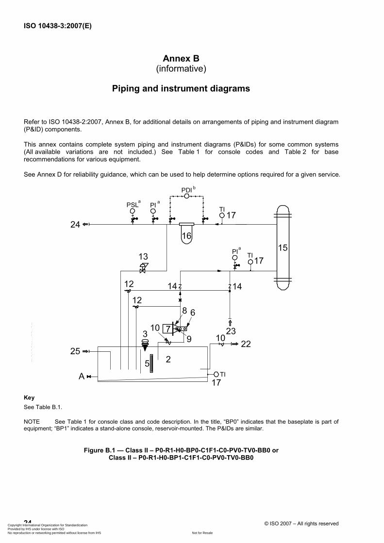
ISO 10438-3:2007(E)
24 © ISO 2007 – All rights reserved
Annex B (informative)
Piping and instrument diagrams
Refer to ISO 10438-2:2007, Annex B, for additional details on arrangements of piping and instrument diagram (P&ID) components.
This annex contains complete system piping and instrument diagrams (P&IDs) for some common systems (All available variations are not included.) See Table 1 for console codes and Table 2 for base recommendations for various equipment.
See Annex D for reliability guidance, which can be used to help determine options required for a given service.
Key See Table B.1.
NOTE See Table 1 for console class and code description. In the title, “BP0” indicates that the baseplate is part of equipment; “BP1” indicates a stand-alone console, reservoir-mounted. The P&IDs are similar.
Figure B.1 — Class II – P0-R1-H0-BP0-C1F1-C0-PV0-TV0-BB0 or Class II – P0-R1-H0-BP1-C1F1-C0-PV0-TV0-BB0
Copyright International Organization for Standardization Provided by IHS under license with ISO
Not for ResaleNo reproduction or networking permitted without license from IHS
--`,,```,,,,````-`-`,,`,,`,`,,`---

ISO 10438-3:2007(E)
© ISO 2007 – All rights reserved 25
Key See Table B.1.
NOTE See Table 1 for console class and code description. In the title, “BP2” indicates a stand-alone console with full baseplate.
Figure B.2 — Class II – P0-R0-H1-BP2-C1F2-C0-PV0-TV1-BB0
Copyright International Organization for Standardization Provided by IHS under license with ISO
Not for ResaleNo reproduction or networking permitted without license from IHS
--`,,```,,,,````-`-`,,`,,`,`,,`---

ISO 10438-3:2007(E)
26 © ISO 2007 – All rights reserved
Key See Table B.1.
NOTE See Table 1 for console class and code description.
Figure B.3 — Class II – P0-R0-H1-BP0-C1F2-C0-PV1-TV1-BB0
Copyright International Organization for Standardization Provided by IHS under license with ISO
Not for ResaleNo reproduction or networking permitted without license from IHS
--`,,```,,,,````-`-`,,`,,`,`,,`---

ISO 10438-3:2007(E)
© ISO 2007 – All rights reserved 27
Key See Table B.1.
NOTE See Table 1 for console class and code description.
Figure B.4 — Class III – P0-R1-H1-BP1-C1F1-C0-PV0-TV1-BB0
Copyright International Organization for Standardization Provided by IHS under license with ISO
Not for ResaleNo reproduction or networking permitted without license from IHS
--`,,```,,,,````-`-`,,`,,`,`,,`---
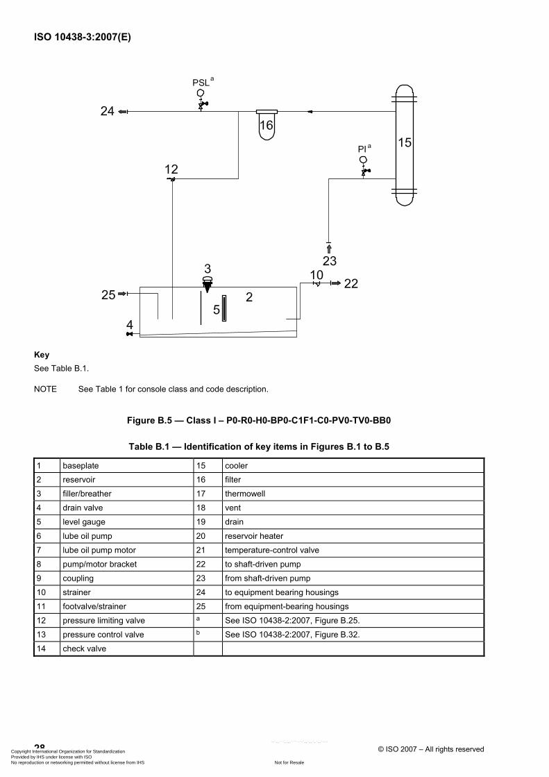
ISO 10438-3:2007(E)
28 © ISO 2007 – All rights reserved
Key See Table B.1.
NOTE See Table 1 for console class and code description.
Figure B.5 — Class I – P0-R0-H0-BP0-C1F1-C0-PV0-TV0-BB0
Table B.1 — Identification of key items in Figures B.1 to B.5
1 baseplate 15 cooler
2 reservoir 16 filter
3 filler/breather 17 thermowell
4 drain valve 18 vent
5 level gauge 19 drain
6 lube oil pump 20 reservoir heater
7 lube oil pump motor 21 temperature-control valve
8 pump/motor bracket 22 to shaft-driven pump
9 coupling 23 from shaft-driven pump
10 strainer 24 to equipment bearing housings
11 footvalve/strainer 25 from equipment-bearing housings
12 pressure limiting valve a See ISO 10438-2:2007, Figure B.25.
13 pressure control valve b See ISO 10438-2:2007, Figure B.32.
14 check valve
Copyright International Organization for Standardization Provided by IHS under license with ISO
Not for ResaleNo reproduction or networking permitted without license from IHS
--`,,```,,,,````-`-`,,`,,`,`,,`---

ISO 10438-3:2007(E)
© ISO 2007 – All rights reserved 29
Annex C (informative)
Inspector's checklist
Table C.1 — Inspector's checklist
Item Date inspected
Inspected by Status
1) Sound pressure level requirements met (4.2.5)
2) Oil characteristics:
a In accordance with specification (4.3.8)
b Hydrotest compatible (ISO 10438-1:2007, 7.3.2.1)
c Run-test compatible (7.3.3.1)
3) Compatible rust preventatives used [ISO 10438-1:2007, 7.4.3 c), 7.4.3 d)]
4) Lube-oil/seal-oil separation demonstrated (if applicable) (4.2.6)
5) System arrangement (4.2.9):
a In accordance with drawings
b Providing adequate clearances
c Providing safe access
6) ASME code stamp (if applicable) (4.2.14):
a Coolers
b Filters
c Accumulators
d Other pressure vessels
7) Welding operators and procedures qualified in accordance with section IX of ASME code:
a Welding of pressure vessels (4.2.14):
(1) Coolers
(2) Filters
(3) Accumulators
(4) Other pressure vessels
b Welding of oil piping (4.2.1)
c Dissimilar-metal welding and weld repairs (4.2.14)
d Verification of welds (ISO 10438-1:2007, 7.2.3.3)
8) Welding procedures (other than above) (ISO 10438-1:2007, 4.6.3):
a Baseplates
b Panels
c Non-pressure ducting
d Other
Copyright International Organization for Standardization Provided by IHS under license with ISO
Not for ResaleNo reproduction or networking permitted without license from IHS
--`,,```,,,,````-`-`,,`,,`,`,,`---
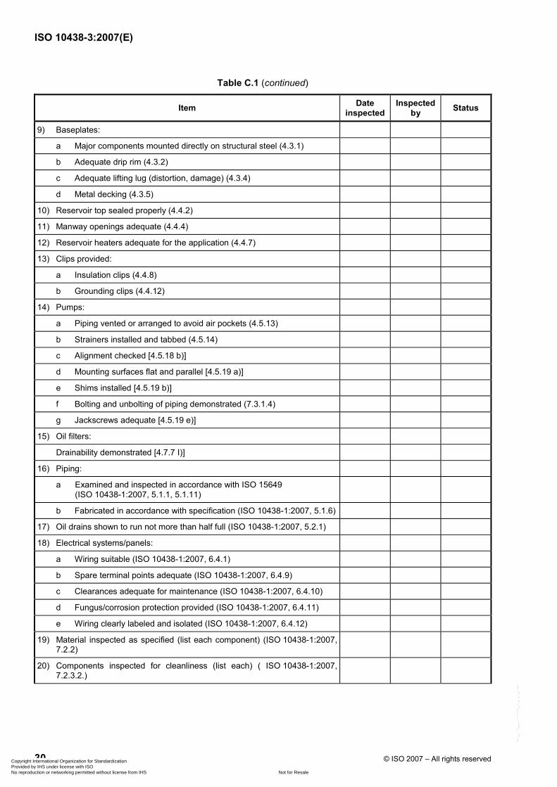
ISO 10438-3:2007(E)
30 © ISO 2007 – All rights reserved
Table C.1 (continued)
Item Date inspected
Inspected by Status
9) Baseplates:
a Major components mounted directly on structural steel (4.3.1)
b Adequate drip rim (4.3.2)
c Adequate lifting lug (distortion, damage) (4.3.4)
d Metal decking (4.3.5)
10) Reservoir top sealed properly (4.4.2)
11) Manway openings adequate (4.4.4)
12) Reservoir heaters adequate for the application (4.4.7)
13) Clips provided:
a Insulation clips (4.4.8)
b Grounding clips (4.4.12)
14) Pumps:
a Piping vented or arranged to avoid air pockets (4.5.13)
b Strainers installed and tabbed (4.5.14)
c Alignment checked [4.5.18 b)]
d Mounting surfaces flat and parallel [4.5.19 a)]
e Shims installed [4.5.19 b)]
f Bolting and unbolting of piping demonstrated (7.3.1.4)
g Jackscrews adequate [4.5.19 e)]
15) Oil filters:
Drainability demonstrated [4.7.7 I)]
16) Piping:
a Examined and inspected in accordance with ISO 15649 (ISO 10438-1:2007, 5.1.1, 5.1.11)
b Fabricated in accordance with specification (ISO 10438-1:2007, 5.1.6)
17) Oil drains shown to run not more than half full (ISO 10438-1:2007, 5.2.1)
18) Electrical systems/panels:
a Wiring suitable (ISO 10438-1:2007, 6.4.1)
b Spare terminal points adequate (ISO 10438-1:2007, 6.4.9)
c Clearances adequate for maintenance (ISO 10438-1:2007, 6.4.10)
d Fungus/corrosion protection provided (ISO 10438-1:2007, 6.4.11)
e Wiring clearly labeled and isolated (ISO 10438-1:2007, 6.4.12)
19) Material inspected as specified (list each component) (ISO 10438-1:2007, 7.2.2)
20) Components inspected for cleanliness (list each) ( ISO 10438-1:2007, 7.2.3.2.)
Copyright International Organization for Standardization Provided by IHS under license with ISO
Not for ResaleNo reproduction or networking permitted without license from IHS
--`,,```,,,,````-`-`,,`,,`,`,,`---
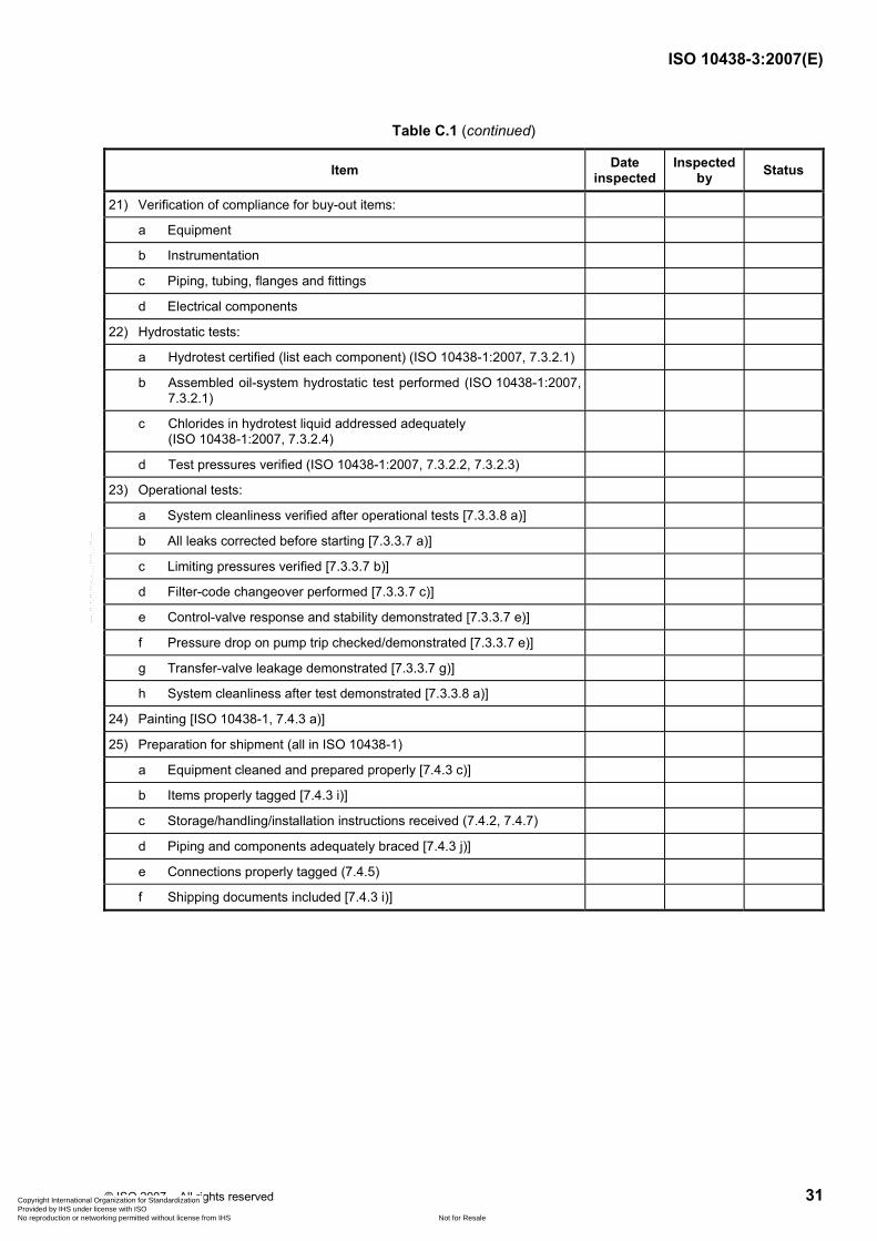
ISO 10438-3:2007(E)
© ISO 2007 – All rights reserved 31
Table C.1 (continued)
Item Date inspected
Inspected by Status
21) Verification of compliance for buy-out items:
a Equipment
b Instrumentation
c Piping, tubing, flanges and fittings
d Electrical components
22) Hydrostatic tests:
a Hydrotest certified (list each component) (ISO 10438-1:2007, 7.3.2.1)
b Assembled oil-system hydrostatic test performed (ISO 10438-1:2007, 7.3.2.1)
c Chlorides in hydrotest liquid addressed adequately (ISO 10438-1:2007, 7.3.2.4)
d Test pressures verified (ISO 10438-1:2007, 7.3.2.2, 7.3.2.3)
23) Operational tests:
a System cleanliness verified after operational tests [7.3.3.8 a)]
b All leaks corrected before starting [7.3.3.7 a)]
c Limiting pressures verified [7.3.3.7 b)]
d Filter-code changeover performed [7.3.3.7 c)]
e Control-valve response and stability demonstrated [7.3.3.7 e)]
f Pressure drop on pump trip checked/demonstrated [7.3.3.7 e)]
g Transfer-valve leakage demonstrated [7.3.3.7 g)]
h System cleanliness after test demonstrated [7.3.3.8 a)]
24) Painting [ISO 10438-1, 7.4.3 a)]
25) Preparation for shipment (all in ISO 10438-1)
a Equipment cleaned and prepared properly [7.4.3 c)]
b Items properly tagged [7.4.3 i)]
c Storage/handling/installation instructions received (7.4.2, 7.4.7)
d Piping and components adequately braced [7.4.3 j)]
e Connections properly tagged (7.4.5)
f Shipping documents included [7.4.3 i)]
Copyright International Organization for Standardization Provided by IHS under license with ISO
Not for ResaleNo reproduction or networking permitted without license from IHS
--`,,```,,,,````-`-`,,`,,`,`,,`---

ISO 10438-3:2007(E)
32 © ISO 2007 – All rights reserved
Annex D (informative)
Guidance to system reliability
Prior to the first edition of ISO 10438 (all parts) in 2003, the predecessor standard, API 614, was directed at systems where only the most critical reliability demands were required. ISO 10438-2 and ISO 10438-4 still require these high-reliability levels for critical non-spared equipment with long mission times. With the introduction of coverage for general-purpose systems in this, the second edition of this part of ISO 10438, a broad new class of systems was introduced for which it is necessary to better balance the initial cost and system reliability to maximize the effectiveness in meeting business requirements.
System design for less-than-critical systems is a trade-off between initial cost associated with taking too much risk vs. taking too little risk of meeting the reliability goal. This relates to the concept of under-investing vs. over-investing. (i.e. the trade-off between system reliability and initial cost) The real issues to determine are: What is the cost of unreliability and how much availability (or unavailability) can you afford?
Methods exist utilizing sophisticated software to aid in the determination of the probability that a particular system can meet the required mission time specified by the business. These methods require reliability data on individual components for input into the system analysis and require a level of sophistication and analysis that is not usually conducted on non-critical systems due to the level of complexity involved in the analysis.
While some sophisticated users take this approach to optimize design for a general-purpose system, the more commonly used approach taken is to provide guidance based on the past experiences of the user to aid in considering the deviations that can be taken from the base systems. (These deviations can either increase or decrease the system reliability and, inversely, the system cost depending upon the mission time and the business need.) These types of deviation decisions have historically been made based on experience, but require an individual or individuals with sufficient operating experience to recognize the potential risks involved in order to make an informed judgment.
One approach to help determine what additional options should be considered (or base requirements deleted) on a given system is to consider possible failure modes of the components and the actions that can be taken to mitigate the risk associated with a particular failure mode. A failure modes and effects analysis (FMEA) has been included in this annex to assist the user in this regard. The probability of a particular failure occurring within the mission time has not been provided due to a lack of industry data and effects of site variations on failure rate; however, the example given explains how a user can utilize the FMEA table to make design decisions based on his perception of the probability of a particular failure mode within the mission time considered.
The FMEA included as Table D.1 is a first attempt to document failure modes on type of equipment covered by ISO 10438 (all parts). The system used in the example has the following characteristics:
⎯ equipment description: lubrication system;
⎯ classification: general-purpose;
⎯ design life of equipment: 20 years;
⎯ mission of equipment: 24 months (provided as an example).
NOTE It is necessary that this be determined by the user (see 4.2.2).
While efforts have been made to make it as complete as possible, the user may wish to add failure modes and risk-reduction activities based on his own experiences.
Copyright International Organization for Standardization Provided by IHS under license with ISO
Not for ResaleNo reproduction or networking permitted without license from IHS
--`,,```,,,,````-`-`,,`,,`,`,,`---
ISO 10438-3:2007(E)
© ISO 2007 – All rights reserved 33
EXAMPLE A user has an application for a lubrication system for an API 610 pump. The business has defined a required mission time of 21 months. In this particular plant, the cooling-water quality is poor and tube fouling has historically been a problem. The user feels that this failure mode reduces the probability of the system reaching the 21 month mission time required for a single cooler. The API 610 base standard system has a single cooler; however, from the FMEA, under failure modes for a cooler, tube fouling is listed along with some possible risk-reduction activities that can be considered. These include purchasing dual coolers with a transfer valve for on-line switching, keeping the water-velocity high and purchasing coolers that have tubes that can be easily rodded out. In this case, due to the poor cooling-water properties, the user specifies that all of the options be taken into consideration in his specification. The use of dual coolers in this instance allows a run-to-failure for this failure mode without affecting the system availability by allowing the standby cooler to be used while the other cooler is repaired.
Copyright International Organization for Standardization Provided by IHS under license with ISO
Not for ResaleNo reproduction or networking permitted without license from IHS
--`,,```,,,,````-`-`,,`,,`,`,,`---
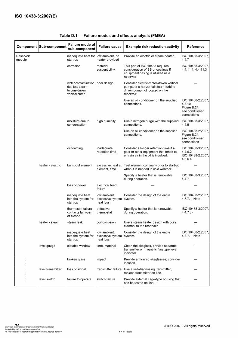
ISO 10438-3:2007(E)
34 © ISO 2007 – All rights reserved
Table D.1 — Failure modes and effects analysis (FMEA)
Component Sub-component Failure mode of sub-component Failure cause Example risk reduction activity Reference
Reservoir module
inadequate heat for start-up
low ambient, no heater provided
Provide an electric or steam heater. ISO 10438-3:2007, 4.4.7
corrosion material susceptibility
This part of ISO 10438 requires consideration of SS or coatings if equipment casing is utilized as a reservoir.
ISO 10438-3:2007,4.4.11.1, 4.4.11.3
water contamination due to a steam-turbine-driven vertical pump
poor design Consider electric-motor-driven vertical pumps or a horizontal steam-turbine-driven pump not located on the reservoir.
—
Use an oil conditioner on the supplied connections.
ISO 10438-2:2007,4.3.10, Figure B.24; see conditioner connections
moisture due to condensation
high humidity Use a nitrogen purge with the supplied connections.
ISO 10438-3:2007,4.4.9
Use an oil conditioner on the supplied connections.
ISO 10438-2:2007,Figure B.24; see conditioner connections
oil foaming inadequate retention time
Consider a longer retention time if a gear or other equipment that tends to entrain air in the oil is involved.
ISO 10438-3:2007,4.4.6.2; ISO 10438-2:2007,4.3.6.4
heater - electric burnt-out element excessive heat at element, time
Test element continuity prior to start-up when it is needed in cold weather.
—
Specify a heater that is removable during operation.
ISO 10438-3:2007,4.4.7
loss of power electrical feed failure
— —
inadequate heat into the system for start-up
low ambient, excessive system heat loss
Consider the design of the entire system.
ISO 10438-2:2007,4.3.7.1, Note
thermostat failure - contacts fail open or closed
defective thermostat
Specify a heater that is removable during operation.
ISO 10438-3:2007,4.4.7 c)
heater - steam steam leak coil corrosion Use a steam heater design with coils external to the reservoir.
—
inadequate heat into the system for start-up
low ambient, excessive system heat loss
Consider the design of the entire system.
ISO 10438-2:2007,4.3.7.1, Note
level gauge clouded window time, material Clean the siteglass, provide separate transmitter or magnetic flag type level indicator.
—
broken glass impact Provide armoured siteglasses; consider location.
—
level transmitter loss of signal transmitter failure Use a self-diagnosing transmitter, replace transmitter on-line.
—
level switch failure to operate switch failure Provide external cage-type housing that can be tested on line.
—
Copyright International Organization for Standardization Provided by IHS under license with ISO
Not for ResaleNo reproduction or networking permitted without license from IHS
--`,,```,,,,````-`-`,,`,,`,`,,`---

ISO 10438-3:2007(E)
© ISO 2007 – All rights reserved 35
Table D.1 (continued)
Component Sub-component Failure mode of sub-component Failure cause Example risk reduction activity Reference
Pump module shaft-driven pump pump failure pump-drive failure (coupling or shaft), pump failure
Provide an auxiliary pump. ISO 10438-3:2007,4.5.4
Provide two motor-driven pumps for on-line replacement.
—
motor driven pump pump failure coupling failure, pump failure, motor failure
Provide an auxiliary pump. ISO 10438-3:2007,4.5.4
loss of power electrical feed Separate electrical feeds on dual motor-driven pumps.
ISO 10438-3:2007, 4.5.3, second paragraph
Provide a HOA or HA switch for auxiliary pump testing.
ISO 10438-1:2007,6.2.1.3
life of pump component
time Specify a larger, lower-speed pump. —
submerged motor-driven pump
pump failure pump component failure
Avoid submerged pumps if local regulations do not allow access while the unit is running.
—
Cooler module shell-and-tube or multi-plate
tube or plate leak corrosion, erosion, manufacturing defect
Consider dual coolers for on-line swapping and on-line repair.
—
A header pressure-control module can keep water out of the oil in the event of failure.
ISO 10438-3:2007,4.6.2.4
Choose alternate materials to withstand corrosion.
—
mis-operation, such as live steam injection for heating
Sparge steam through the water; operate coolers only under the conditions designed.
ISO 10438-3:2007, 4.6.1.6
water side fouling poor cooling water quality, time, corrosion
Consider dual coolers for on-line swapping and on-line repair.
—
Keep water velocity high. ISO 10438-3:2007,4.6.1.2, 4.6.1.8
Choose coolers with straight tubes that can be easily rodded out, or with easily replaceable standard designs.
—
Choose alternate materials to better withstand corrosion.
ISO 10438-3:2007,4.6.2.4
Use a temperature-control bypass. Do not throttle cooling water.
ISO 10438-3:2007, 4.6.1.4
Use a shell-in-tube rather than multi-plate, which is less susceptible to fouling.
—
loss of utility water utility system failure
Add cooling tower or utility water pump redundancy.
—
Car seal open any valves used in the system.
—
multi-plate leak gasket failure Use a fully welded unit (throwaway). —
fin-fan fan failure motor, v-belt, bearings, fan blades
Use multiple fans. ISO 10438-3:2007, 4.6.4.3
Consider direct drive rather than v-belts.
—
oil too cold low ambient Provide a temperature-controlled bypass valve; consider variable shutters.
ISO 10438-3:2007, 4.6.1.4
Copyright International Organization for Standardization Provided by IHS under license with ISO
Not for ResaleNo reproduction or networking permitted without license from IHS
--`,,```,,,,````-`-`,,`,,`,`,,`---

ISO 10438-3:2007(E)
36 © ISO 2007 – All rights reserved
Table D.1 (continued)
Component Sub-component Failure mode of sub-component Failure cause Example risk reduction activity Reference
Filter module collapse filter high ∆p due to cold oil
Make sure that the standby cooler is adequately warmed using a bleed valve prior to switching.
—
high ∆p due to fouling
Consider use of a ∆p transmitter to trend differential if in a service where fouling can be at a high level.
—
incorrect filter element
incorrect element used
Standardize filter element, maintenance procedures.
—
Header pressure-control module
regulator regulator fails closed
regulator failure Specify blocks and bypasses to repair online.
schematic
Supply pressure-reducing module
regulator regulator fails open regulator failure Specify blocks and bypasses to repair online.
schematic
Rundown tank module
— inadequate capacity for specific driver and driven equipment needs
not feasible to make large enough
Provide lube-oil pump backup via alternate source (air, nitrogen, batteries, etc.).
—
atmospheric type fails to flow due to cold oil
low ambient Insulate, heat or use pressurized-type rundown tank.
—
level transmitter loss of signal transmitter failure Use a self-diagnosing transmitter; replace transmitter on-line.
—
no permissive start signal
empty tank Failure to manually open fill bypass or failure in automated fill bypass system.
—
Piping connection leak excessively long term vibration
Provide gusseting, proper support. —
improper installation
Use API RP 686 installation guidelines. —
Tubing connection leak external loading Revise support design; use pipe as alternative.
—
Instrumentation pressure gauge leak due to failed bourdon tube
fatigue, corrosion Keep block valves closed unless actually reading pressure.
ISO 10438-1:2007, 6.3.8
Allow replacing of blocks and bleeds on-line.
—
difficult to read due to vibration
vibration, location — ISO 10438-1:2007, 6.3.8.2
pressure switch switch fails to act when needed
various Use transmitters that have on-line fault-detection, assuming proper response time of system can be attained.
ISO 10438-1:2007, 6.3.2
Periodically test switches and use multiple switches.
—
pressure transmitter
fails to operate internal failure Use multiple transmitters and voting for trip signals.
—
Copyright International Organization for Standardization Provided by IHS under license with ISO
Not for ResaleNo reproduction or networking permitted without license from IHS
--`,,```,,,,````-`-`,,`,,`,`,,`---
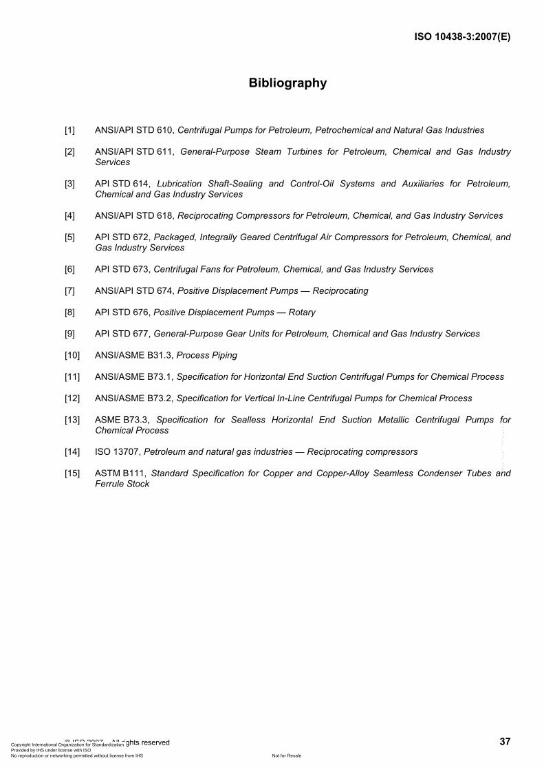
ISO 10438-3:2007(E)
© ISO 2007 – All rights reserved 37
Bibliography
[1] ANSI/API STD 610, Centrifugal Pumps for Petroleum, Petrochemical and Natural Gas Industries
[2] ANSI/API STD 611, General-Purpose Steam Turbines for Petroleum, Chemical and Gas Industry Services
[3] API STD 614, Lubrication Shaft-Sealing and Control-Oil Systems and Auxiliaries for Petroleum, Chemical and Gas Industry Services
[4] ANSI/API STD 618, Reciprocating Compressors for Petroleum, Chemical, and Gas Industry Services
[5] API STD 672, Packaged, Integrally Geared Centrifugal Air Compressors for Petroleum, Chemical, and Gas Industry Services
[6] API STD 673, Centrifugal Fans for Petroleum, Chemical, and Gas Industry Services
[7] ANSI/API STD 674, Positive Displacement Pumps — Reciprocating
[8] API STD 676, Positive Displacement Pumps — Rotary
[9] API STD 677, General-Purpose Gear Units for Petroleum, Chemical and Gas Industry Services
[10] ANSI/ASME B31.3, Process Piping
[11] ANSI/ASME B73.1, Specification for Horizontal End Suction Centrifugal Pumps for Chemical Process
[12] ANSI/ASME B73.2, Specification for Vertical In-Line Centrifugal Pumps for Chemical Process
[13] ASME B73.3, Specification for Sealless Horizontal End Suction Metallic Centrifugal Pumps for Chemical Process
[14] ISO 13707, Petroleum and natural gas industries — Reciprocating compressors
[15] ASTM B111, Standard Specification for Copper and Copper-Alloy Seamless Condenser Tubes and Ferrule Stock
Copyright International Organization for Standardization Provided by IHS under license with ISO
Not for ResaleNo reproduction or networking permitted without license from IHS
--`,,```,,,,````-`-`,,`,,`,`,,`---
ISO 10438-3:2007(E)
ICS 75.180.20 Price based on 37 pages
© ISO 2007 – All rights reserved
Copyright International Organization for Standardization Provided by IHS under license with ISO
Not for ResaleNo reproduction or networking permitted without license from IHS
--`,,```,,,,````-`-`,,`,,`,`,,`---