internal thermal control system hose fluid thermal expansion · internal thermal control system...
TRANSCRIPT

NASA/TM--2001-211330
Internal Thermal Control System Hose
Heat Transfer Fluid Thermal Expansion
Evaluation Test ReportP.O. Wieland
Marshall Space Flight Center, Marshall Space Flight Center, Alabama
H.D. Hawk
Summer High School Apprenticeship Research ProgramMarshall Space Flight Center, Marshall Space Flight Center, Alabama
October 2001
https://ntrs.nasa.gov/search.jsp?R=20010110215 2020-03-29T19:09:51+00:00Z
The NASA STI Program Office...in Profile
Since its founding, NASA has been dedicated to
the advancement of aeronautics and spacescience. The NASA Scientific and Technical
Information (STI) Program Office plays a keypart in helping NASA maintain this importantrole.
The NASA STI Program Office is operated by
Langley Research Center, the lead center forNASA's scientific and technical information. The
NASA STI Program Office provides access to theNASA STI Database, the largest collection of
aeronautical and space science STI in the world. TheProgram Office is also NASA's institutional
mechanism for disseminating the results of its
research and development activities. These resultsare published by NASA in the NASA STI Report
Series, which includes the following report types:
TECHNICAL PUBLICATION. Reports of
completed research or a major significant phase
of research that present the results of NASAprograms and include extensive data or
theoretical analysis. Includes compilations ofsignificant scientific and technical data and
information deemed to be of continuing reference
value. NASA's counterpart of peer-reviewedformal professional papers but has less stringent
limitations on manuscript length and extent of
graphic presentations.
TECHNICAL MEMORANDUM. Scientific and
technical findings that are preliminary or ofspecialized interest, e.g., quick release reports,
working papers, and bibliographies that containminimal annotation. Does not contain extensive
analysis.
CONTRACTOR REPORT. Scientific and
technical findings by NASA-sponsored
contractors and grantees.
CONFERENCE PUBLICATION. Collected
papers from scientific and technical conferences,
symposia, seminars, or other meetings sponsoredor cosponsored by NASA.
SPECIAL PUBLICATION. Scientific, technical,
or historical information from NASA programs,
projects, and mission, often concerned withsubjects having substantial public interest.
TECHNICAL TRANSLATION.
English-language translations of foreign scientific
and technical material pertinent to NASA'smission.
Specialized services that complement the STI
Program Office's diverse offerings include creatingcustom thesauri, building customized databases,
organizing and publishing research results.., even
providing videos.
For more information about the NASA STI ProgramOffice, see the following:
• Access the NASA STI Program Home Page athttp ://www.sti.nasa.gov
• E-mail your question via the Internet tohelp@ sti.nasa.gov
• Fax your question to the NASA Access HelpDesk at (301) 621-0134
• Telephone the NASA Access Help Desk at (301)621-0390
Write to:
NASA Access Help Desk
NASA Center for AeroSpace Information7121 Standard Drive
Hanover, MD 21076-1320

NASA/TM--2001-211330
Internal Thermal Control System Hose
Heat Transfer Fluid Thermal Expansion
Evaluation Test Report
P.O. Wieland
Marshall Space Flight Center, Marshall Space Flight Center, Alabama
H.D. Hawk
Summer High School Apprenticeship Research Program
Marshall Space Flight Center, Marshall Space Flight Center, Alabama
National Aeronautics and
Space Administration
Marshall Space Flight Center • MSFC, Alabama 35812
October 2001

Acknowledgments
Daniell Hawk participated in this project via the Summer High School Apprenticeship Research Program
and assisted in collecting and evaluating test data, preparing plots, and assembling this Technical Memorandum.Bill Barnett, FD21, Marshall Space Flight Center, prepared the test article and test preparation sheet, and John Lowery
and Amos Glenn, ASRI, operated the environmental chamber during the test. Jamie Miernik, Boeing,obtained the hose and end cap that were tested.
Available from:
NASA Center for AeroSpace Information7121 Standard Drive
Hanover, MD 21076 1320
(301) 621 0390
National Technical Information Service
5285 Port Royal Road
Springfield, VA 22161(703) 487 4650
ii

TABLE OF CONTENTS
1. INTRODUCTION ............................................................................................................................
2. TEST OBJECTIVE AND PURPOSE ..............................................................................................
3. APPLICABLE DOCUMENTS ........................................................................................................
4. TESTING .........................................................................................................................................
4.1 Test Method ...............................................................................................................................
4.2 Test Article ................................................................................................................................
4.3 Test Facility ...............................................................................................................................
5. PRETEST PREPARATION AND MEASUREMENTS .................................................................
6. TEST RESULTS AND DISCUSSION ............................................................................................
7. CONCLUSIONS ..............................................................................................................................
APPENDIX A--ITCS HOSE HEAT TRANSFER FLUID THERMAL EXPANSION
EVALUATION TEST PLAN ...................................................................................
APPENDIX B--ITCS INTEGRATED HOSE ASSEMBLY COOLANT EXPANSION
TEST PREPARATION SHEET ................................................................................
1
1
2
2
2
2
3
4
4
6
9
17
°°°
111

LIST OF FIGURES
°
2.
3.
4.
IHA test article .......................................................................................................................
Test article pressure ...............................................................................................................
Test article pressure profiles ..................................................................................................
Estimated temperature to reach the maximum pressure ........................................................
3
4
5
7
iv

LIST OF ACRONYMS
HTF
IHA
ISS
ITCS
MSFC
PACRATS
PTFE
QD
RFCA
TPS
heat transfer fluid
integrated hose assembly
International Space Station
Internal Thermal Control System
Marshall Space Flight Center
Payloads and Components Real-Time Automated Test System
polytetrafluoroethylene
quick disconnect
rack flow control assembly
test preparation sheet

TECHNICALMEMORANDUM
INTERNAL THERMAL CONTROL SYSTEM HOSE HEAT TRANSFER FLUID
THERMAL EXPANSION EVALUATION TEST REPORT
1. INTRODUCTION
The Internal Thermal Control System (ITCS) of the International Space Station (ISS) is designed
to transfer heat to maintain optimum temperatures for the crew and equipment inside the modules.
Excess heat is removed and cool locations are warmed as needed. During assembly of the ISS, jumper
hoses are used by the astronauts on board to connect the ITCS loops in adjacent modules. A jumper hose
with quick disconnects (QDs) and end caps attached is referred to as an integrated hose assembly (IHA).
It would be preferable to launch the IHAs prefilled with heat transfer fluid (HTF), but there is a concern
that in the event of high temperature during storage or transportation, the IHAs may leak or become
damaged due to excessive pressure. To address this concern, a test was requested by the ISS Program
Thermal Control Lead, Joe Chambliss, to evaluate the ability of an IHA to be launched "wet" and safely
accommodate the increased pressure of the HTF if the temperature increased to the worst-case condition
of 60 °C (140 °F). This testing was performed at Marshall Space Flight Center (MSFC) in June 2000 on
a flightlike hose with a flight end cap to evaluate the maximum pressure that would occur under the
worst-case temperature condition. Four cases were run with test conditions subjecting the test article up
to 71 °C (160 °F), and results show that the pressure at this temperature reached -_228 kPa (33 psia), well
below the design maximum of 689 kPa (100 psia). The test conditions and results are described in thisTechnical Memorandum.
2. TEST OBJECTIVE AND PURPOSE
The objective of this test is to simulate the conditions that may be experienced by an isolated
IHA, filled with HTF and capped on both ends. The purpose is to determine whether the IHA can
accommodate the increased pressure due to HTF expansion when heated from room temperature
to 60 °C (140 °F) without exceeding the design maximum pressure of 689 kPa (100 psia), leaking,
or being damaged. In addition, measurement of the bend radius of the hose and of the mass of HTF
in the filled hose are needed for designing the transportation containers.

3. APPLICABLE DOCUMENTS
The following documents axe applicable to this test:
• "ITCS Rack Flow Control Assembly Fill Procedure," SK683-53379, 21 April 1999
• "ITCS Hose HTF Thermal Expansion Evaluation Test Plan," May 2000 (revised June 21, 2000)
(app. A)
• "Test Preparation Sheet," FD21TST-TPS-ITCS-00-001 (app. B).
4. TESTING
The test was performed from June 27-30, 2000. The test method, article, and facility axe de-
scribed in sections 4.1 through 4.3.
4.1 Test Method
A flightlike IHA was tested by simulating the worst-case condition plus 11 °C (20 °F); i.e.,
71 °C (160 °F). The pressure was monitored and the hose was regularly checked for any signs of leakage
or other damage. Four cases were run with increasing temperature profiles: two cases at 60 °C (140 °F),
one case at 66 °C (150 °F), and one case at 71 °C (160 °F). The rate of temperature change, increasing
and decreasing, for each case was <17 °C/hr (30 °F/hr).
The test plan is in appendix A and the test preparation sheet (TPS) is in appendix B.
4.2 Test Article
The test article consisted of an IHA, plus an aluminum adapter block fabricated to attach a
pressure transducer and a three-way valve for connecting a vacuum source and a pressurized tank con-
raining HTE The serial number of the IHA is 683-56836-385. This had been a flight IHA but was
rejected due to a change in materials. A flight-qualified end cap covered the QD at the other end of the
hose. The hose is made of convoluted teflon (polytetrafluoroethylene (PTFE)) with a nominal diameter
of 12.7 mm (0.5 in) and a length of 762 mm (30 in), including fittings. The assembled test article is
shown schematically in figure 1.
2

QD Connector
With Cap
QD1
PressureTransducer
P1
VacuumSource
1/2-in-DiameterHoseApproximately36 in Long
MSFitting
AdapterBlockAB1
ValveVl
HTFSupply
Figure 1. IHA test article.
4.3 Test Facility
The environmental chamber used for this test is an Ecosphere thermal/humidity chamber by
Despatch (model 16664) located in Building 4619 at MSFC. This chamber, designated as TH3, is
capable of maintaining the temperature anywhere in the range of-70 to 180 -°C (-94 to 356 °F). The
chamber allows an unobstructed, usable internal volume that is cube shaped, measuring 1,219 mm
(48 in) deep, 1,118 mm (44 in) high, and 1,168 mm (46 in) wide. The chamber has a front opening door
with a 610-mm (24-in) square view window located in the center of the door.
A Watlow multiloop process controller manages the operation of the chamber and enables the
user to maintain the temperature at a constant value or to continuously vary the temperature according
to a predefined program. The Watlow controller allows the operator to manually enter up to 256 tem-
perature steps, with segment times up to 100 h. Temperatures within the allowable range can be main-
tained to +2 °C (3.6 °F), dry bulb or wet bulb, of the nominal value.
Temperature and pressure data were recorded by the Payloads and Components Real-Time
Automated Test System (PACRATS) every 20 s.
The IHA was filled with HTF in Building 4755, using the same equipment as was used to fill
the ITCS simulator facility.

5. PRETEST PREPARATION AND MEASUREMENTS
The empty test article was weighed and the mass was 1403.6 g (3.07 lb). The bend radius of the
empty hose was measured as =76 mm (3 in). The test article was filled with HTF per procedure SK683-
53379, which involves evacuating the IHA to <50 milliTorr before filling with HTF to 207 kPa (30 psia).
The filling procedure was designed to ensure that no air bubbles were present in the IHA. (The presence
of air bubbles would likely result in higher pressures due to the greater thermal expansion of air com-
pared to water.) After filling with HTF, the bend radius was again measured and found to be =76 mm
(3 in), and the mass was measured as 1532.5 g (3.35 lb). The mass of HTF in the hose was therefore
128.9 g (0.28 lb), or 4.3 g (0.01 lb) for each inch of hose length. At 101 kPa (14.7 psia) and 25 °C
(77 °F), the volume of HTF in the hose is 0.129 L (0.034 gal), or 0.0043 L (0.0011 gal) for each inch
of hose length.
6. TEST RESULTS AND DISCUSSION
During pretest preparation on Friday, June 23, 2000, the test article was pressurized to 207 kPa
(30 psia) during filling with HTE Over the weekend, the pressure dropped to <117 kPa (17 psia) with
no indication that any leakage had occurred. On Monday, June 26, 2000, the test article was repressur-
ized to 207 kPa (30 psia) in Building 4755, then transported to Building 4619 and connected to the data
recording equipment. By the time data recording was initiated, the pressure had dropped to 186 kPa
(27 psia). By Tuesday morning, the pressure had dropped to 162 kPa (23.5 psia), again, with no indica-
tion of leakage (fig. 2). These pressures were all recorded at ambient temperatures. The pressure was
holding at 162 kPa (23.5 psia), indicating that the pressure drop was not due to leakage, and it was
decided to proceed with test case 1 on Tuesday. (The drops in pressure shortly before the beginning
of case 1 axe likely due to temperature drops as air conditioning equipment in the building was
activated.)
34] Case 1 Case 2 Case3 Case4
32_ 140 °F 140 °F 150 °F 160 °F/
3o/ AmbientA 28 Temperature . t[
24
22
20
18 ...................
16
Data Point (time)
Figure 2. Test article pressure.
4
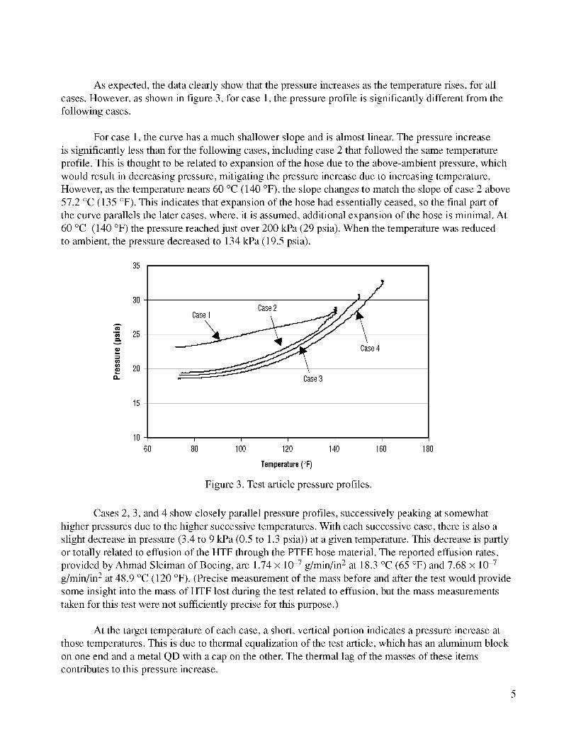
As expected,thedataclearlyshowthatthepressureincreasesasthetemperaturerises,for allcases.However,asshownin figure3, for case1,thepressureprofile issignificantlydifferentfromthefollowingcases.
Forcase1,thecurvehasamuchshallowerslopeandisalmostlinear.Thepressureincreaseissignificantlylessthanfor thefollowingcases,includingcase2thatfollowedthesametemperatureprofile.Thisis thoughtto berelatedto expansionof thehosedueto theabove-ambientpressure,whichwouldresultindecreasingpressure,mitigatingthepressureincreasedueto increasingtemperature.However,asthetemperaturenears60°C(140°F), theslopechangesto matchtheslopeof case2 above57.2°C(135°F).Thisindicatesthatexpansionof thehosehadessentiallyceased,sothefinal partofthecurveparallelsthelatercases,where,it is assumed,additionalexpansionof thehoseis minimal.At60°C (140°F)thepressurereachedjustover200kPa(29psia).Whenthetemperaturewasreducedto ambient,thepressuredecreasedto 134kPa(19.5psia).
35
3O
A
•_ 25
20O.
15
10
Case1 Case2
Case4
I I I I I
60 80 100 120 140 160 180
Temperature(°F)
Figure 3. Test article pressureprofiles.
Cases 2, 3, and 4 show closely parallel pressure profiles, successively peaking at somewhat
higher pressures due to the higher successive temperatures. With each successive case, there is also a
slight decrease in pressure (3.4 to 9 kPa (0.5 to 1.3 psia)) at a given temperature. This decrease is partly
or totally related to effusion of the HTF through the PTFE hose material. The reported effusion rates,
provided by Ahmad Sleiman of Boeing, are 1.74 × 10³ g/min/in 2 at 18.3 °C (65 °F) and 7.68 × 10³
g/min/in 2 at 48.9 °C (120 °F). (Precise measurement of the mass before and after the test would provide
some insight into the mass of HTF lost during the test related to effusion, but the mass measurements
taken for this test were not sufficiently precise for this purpose.)
At the target temperature of each case, a short, vertical portion indicates a pressure increase at
those temperatures. This is due to thermal equalization of the test article, which has an aluminum block
on one end and a metal QD with a cap on the other. The thermal lag of the masses of these items
contributes to this pressure increase.

7. CONCLUSIONS
Thetestarticlewasinitially pressurizedto 207kPa(30psia)withHTF,pertheBoeingprocedurefor filling therackflow controlassembly(RFCA).Asdemonstratedduringthis test,thepressurewilldecreaseto nearambientwithin afewdays,dueprimarilyto expansionof theflexiblehose.Forthis test,thetestarticlewasrepressurized,whichwill makethetestresultsconservative;i.e.,withouttherepressurization,whichisnotcalledfor in theprocedure,themaximumpressureswouldhavebeenlower.Thefollowingconclusionscanbedrawnfromthetestresults:
1. Theinitial dropin pressureatambienttemperaturesbeforecase1is relatedto expansionof theflexiblehose.
Thisconclusionis supportedbythepressuredroplevelingoutpriorto case1,indicatingthatexpansionhadceased,aswell asthebehavioraftercase1,whenthepressurecurvesareessentiallyparallelandthelow pressurepointsaxeveryclose,indicatingthatexpansionof thehosehadessentiallystopped.
2. Theshapeof thecase1pressureprofileisdueto expansionofthehoseaswell asexpansionof theHTFwhileheatingis occurring.
Simultaneousinfluenceof thetwo opposingeffectscausedtheresultingshapefor case1.Expansionof thehoseleadsto decreasedpressurewhileincreasedtemperatureleadsto in-creasedpressureof theHTE It is thoughtthatthehighertemperaturesallowedadditionalhoseexpansionaftertheexpansionhadstabilizedatambienttemperature.Withoutadditionalhoseexpansion,themaximumpressurewouldhavebeen-_241kPa(35psia)for case1.
3. Theslightdropin pressuresatthesametemperatureswithsucceedingcasesisdueto effusionof theHTFthroughthePTFEhose.
Whilecontinuedexpansionof thehosemightalsocausesucharesult,theevenspacingandsmoothcurvesof theprofilesaxemoreconsistentwithgradualfluid loss,whichcouldoccurbyeffusion.Theincreaseineffusionrateasthetemperatureincreasesisreflectedin theslightlybroadeningspacingbetweenthecurvesasthetemperatureincreases.
4. Undertheexpectedworst-casethermalconditions,thepressurein afilledIHA will remainwell belowthemaximumdesignpressure(689kPa(100psia)).
Extrapolatingfromthetestdatato estimatethemaximumallowabletemperature,figure4showsthat689kPa(100psia)wouldnotbereacheduntil-_115°C(240°F).

A
_D
O.
120-
100-
80-
60-
40-
20-
O- I I
0 100 200 240 300
Temperature (°F)
Figure 4. Estimated temperature to reach the maximum pressure.
5. Based on the given thermal conditions and the IHA characteristics, the IHAs can safely
be filled with HTF prior to launch.
Even if the hoses axe repressurized to 207 kPa (30 psia) after expansion has ceased, the esti-
mated maximum pressure at 40 °C (140 °F) is 276 kPa (40 psia), assuming the same pressure
curve but starting at 207 kPa (30 psia).
6. The bend radius of the IHA when filled with HTF is very close to the bend radius of an emptyIHA.
This measurement was made by loosely, but firmly, coiling the IHA, then allowing it to relax
in an unconstrained manner, with the masses of the QD with cap and adapter block with valve
attached at the ends. If necessary, it could be coiled tighter than a 76-mm (3-in) radius, but
that would induce a higher level of stresses.
7

APPENDIX AmlTCS HOSE HEAT TRANSFER FLUID THERMAL
EXPANSION EVALUATION TEST PLAN
9

ITCS Hose
HTF Thermal ExpansionEvaluation Test Plan
Paul Wieland
NASA/MSFC/FD21
256-544-7215
May 2000
(Revised June 21, 2000)
10

Contents
1.0 Introduction ........................................................................................................................................ 3
2.0 Test Objective ..................................................................................................................................... 3
3.0 Test Approach ..................................................................................................................................... 3
4.0 Applicable Documents ........................................................................................................................ 35.0 Test Method ........................................................................................................................................ 3
6.0 Test Requirements .............................................................................................................................. 4
6.1 Materials/Equipment Required ..................................................................................................... 4
6.2 Facility Requirements ................................................................................................................... 4
6.3 Personnel Requirements ................................................................................................................ 5
7.0 Test Procedure .................................................................................................................................... 5
7.1 Pretest Preparation ........................................................................................................................ 6
7.2 Test Steps ...................................................................................................................................... 67.3 Post Test ........................................................................................................................................ 6
8.0 Evaluation Criteria and Risks ............................................................................................................. 6
9.0 Cost and Schedule .............................................................................................................................. 7
10.0 Documentation .................................................................................................................................... 7
Figure 6.1-1.
Figure 6.2-1.
Figures
IHA Test Assembly .............................................................................................................. 4
IHA Coolant Expansion Test Setup ..................................................................................... 5
11

1.0 Introduction
Internal Thermal Control System (ITCS) jumper hoses will be used by the astronauts on-board the
International Space Station (ISS) to connect the ITCS loops in adjacent modules. A jumper hose with
quick disconnects (QD) and end caps attached is referred to as an Integrated Hose Assembly (IHA). It
would be preferable to launch the IHAs already filled with heat transfer fluid (HTF), but there is a
concern that in the event of high temperature during storage or transportation the IHAs may leak or
become damaged due to excessive pressure. To address this concern, a test was requested by the ISS
Program Thermal Control Lead (Joe Chambliss) to evaluate the ability of an IHA to be launched "wet"
and safely accommodate the increased pressure of the HTF if the temperature increased to the worst-
case condition of 140°1. This test plan describes the equipment and facility requirements for performing
this test, general test procedures, and the evaluation criteria.
2.0 Test Objective
The objective of this test is to simulate the conditions which may be experienced by an isolated IHA,
capped on both ends, and to determine whether the IHA can accommodate the increased pressure due to
HTF expansion when heated from room temperature to 140°1, without exceeding the design maximum
pressure of 100 psia, leaking, or being damaged.
3.0 Test Approach
A flight-like IHA (serial number 683-56836-385) will be tested by simulating the worst-case condition
plus 20°1, i.e., 160°1. The pressure will be monitored and the hose will also be checked for any signs of
leakage or other damage.
Note: The hose was originally flight hardware but is now obsolete due to a change in materials, however,
the cap for the hose is flight hardware and appropriate procedures must be followed.
4.0 Applicable Documents
Internal Thermal Control System Rack Flow Control Assembly Fill Procedure, SK683-53379, 21 April1999
5.0 Test Method
The test IHA will be filled with coolant per procedure SK683-53379, which involves evacuating the IHA
to <50 milliTorr before filling with HT1. The worst-case conditions will be duplicated by heating a
coolant-filled, sealed IHA in an environmental chamber, located in Building 4619 at the Marshall Space
Flight Center (MSFC). Four cases will be run: two with a target temperature of 140°1, one with a target
of 150°1, and one with a target of 160°E
12

6.0 Test Requirements
Controlled conditions axe needed as well as the means to monitor the pressure in the IHA. The IHA, and
equipment that directly connects to the IHA fittings, must be cleaned to cleanliness level 300. Appropri-
ate safety precautions must also be taken. The materials and equipment that are required and the facility
support requirements axe described below.
The hose will be filled with HTF according to procedure SK683-53379.
6.1 Materials/Equipment Required
A suitable flight-like IHA (undamaged), fittings and connectors, a pressure transducer compatible with
operation at 160°1, and HTF axe required. The IHA to be provided by Boeing has a QD connector on
one end and a threaded MS fitting on the other. A connector block is required for attaching the pressure
transducer, and vacuum and fill valve to the IHA. This configuration is shown in Figure 6.1-1. The
pressure transducer must have current calibration for the test.
PressureTransducer
P1
VacuumSource
QD Connector
With Cap
QD1
1/2-in-DiameterHose MS Fitting Valve
Approximately36 in Long Adapter VlBlockAB1
HTFSupply
Figure 6.1-1. IHA Test Assembly
6.2 Facility Requirements
Facility support requirements include:
1. A suitable test preparation area to prepare the IHA test article for testing,
2. The means to evacuate the IHA test article and fill it with HT1,
3. An environmental chamber capable of cycling between ambient conditions and the test target tem-
peratures and capable of maintaining the target temperatures for the required durations (sufficient to
ensure thermal equilibrium with the IHA test article),
4. A means to record the data (pressure, temperature, time), and
5. Suitable precautions in the event of leakage of the IHA test article or other safety-related concerns.
The IHA test article will be installed in the environmental chamber as indicated in figure 6.2-1. The
pressure transducer will have data lines which connect to recording equipment outside the chamber.
13

Pressure _/_
TransducerI IP]
QD Connector I IWithCap I I m
1/_-in-DiameterHose _ MSFitting_ ValveApproximately36in Long_ Adapter (OttPosition)
BlockAB1
EnvironmentalChamber
Figure 6.2-1. IHA Coolant Expansion Test Setup
6.3 Personnel Requirements
In addition to test personnel from FD21 and ED26, quality assurance personnel from QS 10 will need to
approve the test due to the use of a flight hardware end cap.
7.0 Test Procedure
The test procedure should include the following steps.
7.1 Pretest Preparation
1. Connect the required fittings to the IHA, including valve and hoses required for filling the IHA test
article with HTE
2. Attach a pressure gauge and ensure proper tightness of all fittings.
3. Fill the test article with HTF by procedure SK683-53379. (Evacuate the test article to <50 millitorr
prior to ensure complete fill with HTF).
4. Place the test article in the environmental chamber and connect to the monitoring equipment.
5. Place paper (or other means to readily detect leakage) under the test article.
7.2 Test Steps
6. Record the initial pressure (~ 15 psig) and temperature. Increase the temperature in the chamber at a
maximum rate of 30°F/hour. Record the temperature and pressure every 10 minutes (or more fre-
quently).
7. If the pressure reaches 100 psia during temperature ramp-up, STOP the test immediately and reduce
the temperature.
14

8. If thepressure< 100psiawhenthetargettemperatureisreached(140°1,140°1,150°1,and160°F)holdthetemperaturelongenoughto ensurethoroughheatingandto checkthroughthechamberwindowfor signsof leakage.Noteanyleakagein thetestlog.
9. Reducethetemperatureatamaximumrateof 30°F/houruntil neax-ambienttemperatureisreached.10.Openthechamberandcheckthetestarticlefor indicationsof leakageordamage.11.Returnto step7 for thenexttargettemperature.12.Uponcompletionof thelasttargettemperaturecycle,removethetestarticlefromthechamberand
inspectfor indicationsof leakageordamage.
7.3 Post Test
Following completion of the test cycles, the test article is to be disassembled and the cap and hose
cleaned to specification level 300 for return to Boeing.
A report on the results of the testing will be prepared.
8.0 Evaluation Criteria and Risks
The purpose of the testing is to determine whether the IHA can accommodate the worst-case scenario of
140°1. To ensure this, the testing will reach a high temperature of 160°1. To demonstrate that the hose
can successfully do this, the pressure must remain below the 100 psia limit while at this temperature, no
leakage should occur, and the hose should remain undamaged.
Potential risks to performing this test relate to acquisition of materials and availability of facilities and
personnel. Presently, the need for funding has not been identified, though it may be necessary to pur-
chase items such as fittings for attaching the pressure gauge.
9.0 Cost and Schedule
It is expected that the test will utilize existing equipment and materials, and therefore require minimal
cost and time. No requirements for purchasing items have presently been identified. The IHA and cap
will be loaned by Boeing. A preliminary schedule is given below. The duration required for acquiring
the IHA and cleaning parts is unknown. The test itself is expected to take only a few days.
15

Activity Week1 2 3 4 5 6
Preparetestplanandprocedure, xxxxxxxxxxxxxxxxxpaperworkfor environmentalchamber,QA,etc.Acquirehoseandparts xxxxxAssembletestarticle(includingcleaning, xxxxxxxxxasneeded)Performtest xxxxxPost-testactivity(includingcleaningand xxxxxxreturnof hoseandcapto Boeing)Testreport xxxxx
10.0 Documentation
Documentation of this project includes this test project plan, a test procedure, a test plan (TPS) prepared
by the test group, test log and raw test results from the test conductor, and a report on the results of the
test.
16

APPENDIX BmlTCS INTEGRATED HOSE ASSEMBLY COOLANT
EXPANSION TEST PREPARATION SHEET
17

t @
_a '"_."_\_..,_o _ "................................................................•- ,_,.,._c_. ...............................................................
19

............. Bill Ba_o:e_MSgC _a:rm 2¢g i _Rcv_ Ngve.mbe.," I_}
2O

iiiiiiiiii!ii!iiiii!il,ii!i
21

REPORT DOCUMENTATION PAGE Form ApprovedOMB No. 0704-0188
Public reporting burden for this collection of information is estimated to average 1 hour per response, including the time for reviewing instructions, searching existing data sources,gathering and maintaining the data needed, and completing and reviewing the collection of information. Send comments regarding this burden estimate or any other aspect of thiscollection of information, including suggestions for reducing this burden, to Washington Headquarters Services, Directorate for Information Operation and Reports, 1215 JeffersonDavis Highway, Suite 1204, Arlington, VA 22202-4302, and to the Office of Management and Budget, Paperwork Reduction Project (0704-0188), Washington, DC 20503
1. AGENCY USE ONLY (Leave Blank) 2. REPORT DATE 3. REPORT TYPE AND DATES COVERED
October 2001 Technical Memorandum4. TITLE AND SUBTITLE 5. FUNDING NUMBERS
Internal Thermal Control System Hose Heat Transfer Fluid
Thermal Expansion Evaluation Test Report
6. AUTHORS
P.O. Wieland and H.D. Hawk*
7. PERFORMING ORGANIZATION NAMES(S) AND ADDRESS(ES)
George C. Marshall Space Flight Center
Marshall Space Flight Center, AL 35812
9. SPONSORING/MONITORING AGENCY NAME(S) AND ADDRESS(ES)
National Aeronautics and Space Administration
Washington, DC 20546_0001
8. PERFORMING ORGANIZATION
REPORT NUMBER
M-1031
10. SPONSORING/MONITORINGAGENCY REPORT NUMBER
NASA/TM--2001-211330
11. SUPPLEMENTARY NOTES
Prepared by Flight Projects Directorate
*Summer High School Apprenticeship Research Program, Marshall Space Flight Center, AL
12a. DISTRIB UTION/AVAILABILITY STATEMENT
Unclassified-Unlimited
Subject Category 18Nonstandard Distribution
12b. DISTRIBUTION CODE
13. ABSTRACT (Maximum 200 words)
During assembly of the International Space Station, the Internal Thermal Control Systems inadjacent modules are connected by jumper hoses referred to as integrated hose assemblies
(IHAs). A test of an IHA has been performed at the Marshall Space Flight Center to determine
whether the pressure in an IHA filled with heat transfer fluid would exceed the maximum design
pressure when subjected to elevated temperatures (up to 60 °C (140 °F)) that may be experienced
during storage or transportation. The results of the test show that the pressure in the IHA remains
below 227 kPa (33 psia) (well below the 689 kPa (100 psia) maximum design pressure) even at atemperature of 71 °C (160 °F), with no indication of leakage or damage to the hose. Therefore,
based on the results of this test, the IHA can safely be filled with coolant prior to launch. The testand results are documented in this Technical Memorandum.
14. SUBJECT TERMS
ITCS, jumper hose, thermal control system
17. SECURITY CLASSIFICATION
OF REPORT
UnclassifiedNSN 7540-01-280-5500
18. SECURITY CLASSIFICATION
OF THIS PAGE
Unclassified
15. NUMBER OF PAGES
2816. PRICE CODE
19, SECURITY CLASSIFICATION 20, LIMITATION OF ABSTRACT
OF ABSTRACT
Unclassified UnlimitedStandard Form 298 (Rev. 2-89)Prescribedby ANSISld 239 18298 102