interior mapping - proun · interior mapping a new technique for rendering realistic buildings...
TRANSCRIPT

CGI 2008 Conference Proceedings manuscript No.(will be inserted by the editor)
Joost van Dongen
Interior MappingA new technique for rendering realistic buildings
Keywords interior · GPU shader · architectureAbstract Interior Mapping is a new real-time shadertechnique that renders the interior of a building whenlooking at it from the outside, without the need to actu-ally model or store this interior. With Interior Mapping,raycasting in the pixel shader is used to calculate thepositions of floors and walls behind the windows. Build-ings are modelled in the same way as without InteriorMapping and are rendered on the GPU. The numberof rooms rendered does not influence the framerate ormemory usage. The rooms are lit and textured and canhave furniture and animated characters. The interiorsrequire very little additional asset creation and no extramemory. Interior Mapping is especially useful for addingmore depth and detail to buildings in games and otherapplications that are situated in large virtual cities.
1 Introduction
Many new games and virtual worlds feature large citiesthrough which the player can move; take for examplegames like the Grand Theft Auto-series, Crackdown andSuperman Returns: The Video Game, and the use of vir-tual 3D cities in online communities, simulations and vir-tual tourism. For a significant part, the graphical qualityof these games is determined by how the buildings arerendered. These can have a certain amount of polygonaldetail, depending on the desired size of the city and thedynamic loading system used, but the aforementionedapplications all have in common that the cities are toolarge to model detailed buildings using geometry and stillachieve interactive framerates while doing so. To dealwith this, this paper introduces a new technique thatsignificantly increases the graphical quality of buildingsin real-time applications.
Utrecht University and Ronimo GamesE-mail: [email protected]
Fig. 1 Buildings with their interiors rendered with InteriorMapping. The geometry of the buildings consists of simplecubes only. Note how the interiors are textured and drawnperspectively correct.
Throughout the years, many techniques have beendeveloped and used to visualise buildings as realisticallyand detailled as possible while still keeping framerates in-teractive. Geometry is often kept relatively simple, whiledetails are added through the use of textures [4]. Orig-inally, textures were only used to change the colours ofsurface elements. When adding details, this tends to lookas if pictures of details have been glued on to a flat sur-face, instead of as if the details are really there. Onetechnique that deals with the shading of details is bumpmapping [1]. Unlike in the case of standard textures,with bump mapping, details are correctly lit with re-spect to the lighting in the scene. This can be extended

2 Joost van Dongen
through horizon mapping [12], to show the shadows ofthese details. In addition to bump mapping, normal map-ping [7] is also often used, which stores the normals ofeach texture element, instead of their height. All theaforementioned techniques have in common that they donot correctly visualise the parallax effect when perspec-tive changes. Displacement mapping [15] fixes this byrendering height-field surface details perspectively cor-rect.
The texturing techniques mentioned above can beused to add details to buildings. There is also a num-ber of techniques that have been developed specificallyto quickly render more distant buildings and objects, asthey are smaller in view and can thus be simplified. Dis-playing simpler geometry through level of detail [6] andlower resolution textures through mipmaps [18] are com-monly used techniques for this. More rigorous is replac-ing distant objects by imposters [11] or turning completegroups of buildings into single blocks with height fieldshapes inside, which are rendered through the use of anextension to displacement mapping called block maps [5].This way, hardly any polygons are needed, while rela-tively complex shapes can still be rendered with reduceddetail.
None of the techniques above makes it possible torender the interiors of buildings. However, interiors areimportant for the graphical quality of a virtual city, as itsbuildings contain many windows through which interiorsshould be visible. But as interiors are often not requiredfor gameplay, they are usually left out entirely, exceptin those instances where the interior can be entered bythe player (see for example Grand Theft Auto). Addingthe interiors of many buildings would require an enor-mous amount of polygons, which is not feasible when in-teractive framerates are required. Therefore, some othersolution is required to render windows. Two simple tech-niques are used in most games and interactive applica-tions today: either windows are fully reflective, not al-lowing a look inside, or some details very close to thewindow are drawn into the diffuse texture and the restof the interior is left black.
One way to add perspectively correct interiors wouldbe through the use of displacement mapping. If the dis-placement map is calculated separately from the exte-rior texture, then it could handle geometrically correctrooms. However, because displacement maps do not sup-port texturing on surfaces that are perpendicular to theoriginal polygonal surface, this would leave all walls withstretched coloured lines, except for the back wall, whichcould still use a real texture.
To fix this, textures can be added to all the walls ofthe interior through the use of indices from the displace-ment map into an extra texture, as is done with blockmaps [5]. Block maps cannot render furniture or charac-ters inside the room, though, because they are limitedto height field geometry. Also, if the viewer watches aroom at the corner of a building, she would see a dif-
ferent room through the windows on the different walls.This would be awkward, as it should in fact be the sameroom, only seen through different windows. Finally, tovary the textures on the walls per room, knowledge ofwhich wall is being rendered would be required and isnot readily available with block maps.
Another technique that could render interiors, is gen-eralised displacement mapping [17]. This technique couldrender interiors of any complexity, but has a numberof drawbacks that make it ultimately unsuitable. Themost important problem is that generalised displacementmaps use too much memory. After heavy compression, amap with a resolution of 128x128 pixels still requires 4mbof memory, while a standard texture of the same dimen-sion, as can be used with Interior Mapping, requires only48kb of memory, or 8kb if DXT1 texture compression [2]is used. Also, with generalized displacement mapping itis not possible to separately animate a single characteror object in the interior and walls cannot be varied in-dependently of each other.
To deal with the problem of rendering the interiors ofbuildings, in this paper, Interior Mapping is introduced.This new technique solves the aforementioned issues withblock maps and generalised displacement maps by di-rectly rendering virtual walls through raycasting. TheInterior Mapping algorithm knows which wall in whichroom it is rendering and can use this information to varylighting and textures per room. Furniture and characterscan be added through the use of furniture planes.
An added benefit of Interior Mapping is that it caneasily be coupled with procedurally generated buildings,like in [13] and [19]. Most procedural city and buildinggeneration systems do not take interiors into account.Interior Mapping could easily be added to the buildingsthat these systems generate and works well even withbuildings that have curved walls.
Although Interior Mapping is a technique that ren-ders actual interiors, it does not need to model or storethem in geometry. The walls of the rooms of the inte-rior only exist as virtual geometry in the shader. Foreach pixel, the ray from the camera to the point on thebuilding that is being rendered is intersected with thewalls of the interior. Because the interior walls are reg-ularly spaced, the ray can be collided in constant time,regardless of the number of rooms in a building or thenumber of buildings. Because it is shader-based, it is easyto turn Interior Mapping off for level of detail or lowerquality rendering on older GPUs. Models do not needto be changed to make Interior Mapping possible, so theeffect can quickly be added to cities that have alreadybeen created or are near completion.
Because the raycasting is done for each individualpixel that is rendered and takes the camera direction intoaccount, the result is that perspectively correct roomsare rendered inside the building when looking at it fromthe outside. This can then be combined with a texturethat stores where windows are, so that the interiors are

Interior Mapping 3
only visible through the windows. By blending the inte-rior’s colour with a reflection map, both the interior andthe reflections in the windows can be shown. See figure 1for an example of what can be achieved using InteriorMapping. Note that the buildings here are modelled assingle blocks.
Interior Mapping uses ray casting on the GPU, a re-search field that has quickly evolved since the introduc-tion of programmable shaders. Here, a major trend isto turn the GPU into a full raytrace renderer [3], whichmeans that the rasterizing functionality of the GPU isworked around to create a renderer that utilises the vec-tor processing power of the GPU, but does not use theGPU’s approach to rendering. Contrary to this approachhowever, Interior Mapping does not seek to replace ras-terised GPU rendering, but actually to enhance it. Thus,it is more closely connected to techniques like displace-ment mapping and papers on topics like ambient occlu-sion [16]. Nonetheless, using the regularity of internalstructures in the way that Interior Mapping does, doesseem to be a novelty among existing GPU raycastingtechniques.
Interior Mapping can be implemented in such a way,that the number of shader instructions is small enough tobe able to calculate the effect within the 64 instructionsallowed in pixel shader model 2.0 [10], and also add adiffuse and reflection map in the same pass. More effectscan be added to the basic algorithm to create additionaldetails.
The remainder of this paper is structured as follows:section 2 explains how Interior Mapping works. Section3 analyses the performance of Interior Mapping and sec-tion 4 looks into a number of extensions to the basictechnique.
2 The algorithm
For ease of understanding, the simplest case is consideredfirst: only ceilings and floors are being rendered. Walls,lighting and exterior textures will be added later.
2.1 Ceilings
For the Interior Mapping algorithm, the 3D space is con-sidered to have ceilings at regular distances. Each ceilingis an infinite plane parallel to the XZ-plane. Intersectinga ray with a horizontal plane is a very simple thing to do,but the main point to Interior Mapping is to calculateefficiently which plane to use for a particular pixel.
When the pixel shader renders a pixel of a polygonto the screen, this pixel also has a position in the 3Dworld. This position is calculated in object space and theposition of the camera is transformed into object space aswell. When handling a ray from the camera to this pixelwith a camera that is tilted upwards, the ceiling just
Fig. 2 Visualisation in 2D of the variables in the formulaabove.
above the pixel needs to be found. This can be done bytaking the ceiling-function of the y-position of the pixel,divided by the distance d between ceilings. Afterwards,the height that has been found should be multiplied withd again to get the actual height of the ceiling. In Cg, thissimply comes down to ceil(y/d) · d. When the camera istilted downwards, the ceiling (or actually the floor) thatis one position lower must be used, so in that case theheight is at (ceil(y/d) − 1) · d.
Now that the height of the ceiling is known, the rayfrom the camera to the pixel can be intersected with theceiling to find the position where the ray hits the ceiling.This is visualised in figure 2.
The result is the position of the intersection, but whatis needed is a colour for the pixel. This can easily beobtained by using the x- and z-coordinates of the inter-section as the uv-coordinates for a texture read for theceiling or the floor. To scale the texture to the desiredsize, the coordinates can be multiplied by some constant.
By performing all the calculations in object space,the walls can be rotated by rotating the space of theobject itself. This way the walls in different buildings donot have to be parallel.
Note that an exactly horizontal ray will result in adivision by zero. However, GPUs do not crash on this andthe visual artefacts this results in are so rare in practicethat this problem is negligible.
2.2 Walls
So far only horizontal planes have been considered. How-ever, real interiors do not only have floors and ceilings,but also walls. These can be added by using exactly thesame calculations as were used for the ceilings, but nowwith XY- and YZ-planes, instead of XZ-planes. The in-tersection of the ray is thus calculated with three differ-ent planes.
Of the resulting three intersections, the one closestto the camera will be used. To be able to use differenttextures for the ceilings, floors and walls, the texturecorresponding to the closest intersecting plane is used.
4 Joost van Dongen
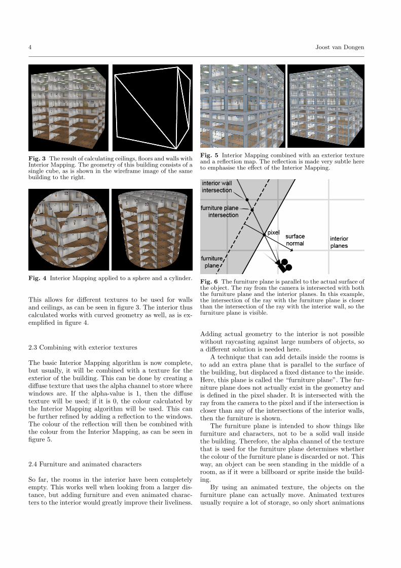
Fig. 3 The result of calculating ceilings, floors and walls withInterior Mapping. The geometry of this building consists of asingle cube, as is shown in the wireframe image of the samebuilding to the right.
Fig. 4 Interior Mapping applied to a sphere and a cylinder.
This allows for different textures to be used for wallsand ceilings, as can be seen in figure 3. The interior thuscalculated works with curved geometry as well, as is ex-emplified in figure 4.
2.3 Combining with exterior textures
The basic Interior Mapping algorithm is now complete,but usually, it will be combined with a texture for theexterior of the building. This can be done by creating adiffuse texture that uses the alpha channel to store wherewindows are. If the alpha-value is 1, then the diffusetexture will be used; if it is 0, the colour calculated bythe Interior Mapping algorithm will be used. This canbe further refined by adding a reflection to the windows.The colour of the reflection will then be combined withthe colour from the Interior Mapping, as can be seen infigure 5.
2.4 Furniture and animated characters
So far, the rooms in the interior have been completelyempty. This works well when looking from a larger dis-tance, but adding furniture and even animated charac-ters to the interior would greatly improve their liveliness.
Fig. 5 Interior Mapping combined with an exterior textureand a reflection map. The reflection is made very subtle hereto emphasise the effect of the Interior Mapping.
Fig. 6 The furniture plane is parallel to the actual surface ofthe object. The ray from the camera is intersected with boththe furniture plane and the interior planes. In this example,the intersection of the ray with the furniture plane is closerthan the intersection of the ray with the interior wall, so thefurniture plane is visible.
Adding actual geometry to the interior is not possiblewithout raycasting against large numbers of objects, soa different solution is needed here.
A technique that can add details inside the rooms isto add an extra plane that is parallel to the surface ofthe building, but displaced a fixed distance to the inside.Here, this plane is called the “furniture plane”. The fur-niture plane does not actually exist in the geometry andis defined in the pixel shader. It is intersected with theray from the camera to the pixel and if the intersection iscloser than any of the intersections of the interior walls,then the furniture is shown.
The furniture plane is intended to show things likefurniture and characters, not to be a solid wall insidethe building. Therefore, the alpha channel of the texturethat is used for the furniture plane determines whetherthe colour of the furniture plane is discarded or not. Thisway, an object can be seen standing in the middle of aroom, as if it were a billboard or sprite inside the build-ing.
By using an animated texture, the objects on thefurniture plane can actually move. Animated texturesusually require a lot of storage, so only short animations
Interior Mapping 5
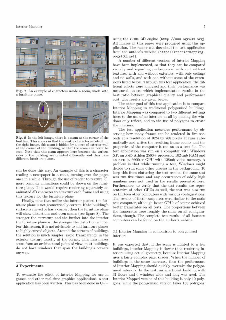
Fig. 7 An example of characters inside a room, made witha furniture plane.
Fig. 8 In the left image, there is a seam at the corner of thebuilding. This shows in that the centre character is cut-off. Inthe right image, this seam is hidden by a piece of exterior wallat the corner of the building, so that the seam can never beseen. Note that this seam appears here because the varioussides of the building are oriented differently and thus havedifferent furniture planes.
can be done this way. An example of this is a characterreading a newspaper in a chair, turning over the pagesonce in a while. Through the use of render to texture [8],more complex animations could be shown on the furni-ture plane. This would require rendering separately ananimated 3D character to a texture each frame and usingthis texture for the furniture plane.
Finally, note that unlike the interior planes, the fur-niture plane is not geometrically correct. If the building’ssurface is curved or has a corner, then the furniture planewill show distortions and even seams (see figure 8). Thestronger the curvature and the further into the interiorthe furniture plane is, the stronger the distortion will be.For this reason, it is not advisable to add furniture planesto highly curved objects. Around the corners of buildingsthe solution is much simpler: avoid transparency in theexterior texture exactly at the corner. This also makessense from an architectural point of view: most buildingsdo not have windows that span the building’s cornersanyway.
3 Experiments
To evaluate the effect of Interior Mapping for use ingames and other real-time graphics applications, a testapplication has been written. This has been done in C++
using the ogre 3D engine (http://www.ogre3d.org).All images in this paper were produced using this ap-plication. The reader can download the test applicationfrom the author’s website (http://interiormapping.oogst3d.net).
A number of different versions of Interior Mappinghave been implemented, so that they can be comparedvisually and regarding performance: with and withouttextures, with and without exteriors, with only ceilingsand no walls, and with and without some of the exten-sions listed below. Through this test application, the dif-ferent effects were analysed and their performance wasmeasured, to see which implementation results in thebest ratio between graphical quality and performancecost. The results are given below.
The other goal of this test application is to compareInterior Mapping to traditional polygonised buildings.Interior Mapping was compared to two different settingshere: to the use of no interiors at all by making the win-dows only reflect, and to the use of polygons to createthe interiors.
The test application measures performance by ob-serving how many frames can be rendered in five sec-onds at a resolution of 1024 by 768 pixels. It runs auto-matically and writes the resulting frame-counts and theproperties of the computer it ran on to a text-file. Thetest application was run on a computer with WindowsXP, an amd Athlon 2500+ processor, 1024mb RAM andan nvidia 6600gt GPU with 128mb video memory. Aproblem is that while running a test, Windows mightdecide to run some other process in the background. Tokeep this from cluttering the test results, the same testwas run five times and any occurrences of oddly highnumbers were not used in the results presented here.Furthermore, to verify that the test results are repre-sentative of other GPUs as well, the test was also runon thirteen other computers with various configurations.The results of these computers were similar to the maintest computer, although faster GPUs of course achievedbetter framerates on all tests. The proportions betweenthe framerates were roughly the same on all configura-tions, though. The complete test results of all fourteencomputers can be found on the author’s website.
3.1 Interior Mapping in comparison to polygonisedinteriors
It was expected that, if the scene is limited to a fewbuildings, Interior Mapping is slower than rendering in-teriors using actual geometry, because Interior Mappinguses a fairly complex pixel shader. When the number ofbuildings in the scene increases, then the performanceof Interior Mapping should quickly overtake the polygo-nised interiors. In the test, an apartment building with31 floors and 6 windows wide and long was used. TheInterior Mapped version of this building is only 10 poly-gons, while the polygonised version takes 158 polygons.

6 Joost van Dongen
Fig. 9 Comparison between Interior Mapped buildings andpolygonised buildings with interiors. The graph shows thenumber of frames rendered in 5 seconds for different num-bers of buildings in the scene. More frames means a higherframerate and is thus better.
The Interior Mapped building can be rendered in a singledraw call, while the polygonised version takes five drawcalls. For the polygonised version, floors, ceilings andwalls each use a different tiling texture and can there-fore not be rendered in a single draw call. After that thereflection in the windows is first drawn and then the ex-terior walls. The version of Interior Mapping that wasused here has four different textures for walls, ceilingsand floors, while no lighting is calculated on the interi-ors.
For the Interior Mapped buildings, z-cull [9] is used.This is a technique where objects are first rendered onlyto the z-buffer and after that are rendered normally. Ren-dering to the z-buffer can be done very quickly, becauseit does not require the calculation of lighting, colour orcomplex effects like Interior Mapping. On the secondpass, the z-buffer has already been filled with correctdepths, so only the actually visible pixels are renderedand there is no overdraw at all. This greatly increasesthe performance of Interior Mapping, because overdrawmeans that Interior Mapping is performed several timeson the same pixel on the screen. With z-cull, this neveroccurs. The actual performance increase of adding z-cullcan vary widely from situation to situation, because itdepends on the scene, the rendering order of the poly-gons and the camera angle. A test was performed with asingle mesh that contained lots of buildings in a grid anda camera rotating around this scene. The results of thistest show that in this specific case, the number of framesrendered in five seconds increases from 881 to 1265 whenz-cull is used, an increase of 44%. This demonstrates thatthe performance of Interior Mapping can indeed greatlybenefit from the use of z-cull. Because the framerate ofthe polygonised buildings is mainly dependent on theprocessing of the polygons, z-cull does not help there atall. In fact, all polygons need to be processed twice, soit even results in worse performance.
The graph in figure 9 shows how the number of framesrendered in five seconds changes when the number ofbuildings in the scene increases. As can be seen, theInterior Mapped buildings quickly overtake the polygo-nised ones. At 100 buildings, Interior Mapping alreadyachieves a better framerate. This shows that the perfor-mance of the polygonised buildings is mainly dependenton the number of buildings, or in fact on the numberof triangles, while the performance of Interior Mappingmainly depends on the number of Interior Mapped pix-els that are actually drawn. The number of triangles ishardly relevant for Interior Mapping, because the poly-gon count is so low, that this is a negligible factor. At 500buildings, Interior Mapping still only requires 5,000 poly-gons, whereas the polygonised buildings require 79,000polygons. The reason why the Interior Mapped build-ings do show a decrease in performance, is because thehigher number of buildings still requires a higher num-ber of draw calls. A draw call for a single object is anexpensive operation, even if the object contains only 10triangles and has no visible pixels.
3.2 Performance of the various versions of InteriorMapping
The previous paragraph showed that from a performancestandpoint, Interior Mapping is better for large citiesthan creating interiors using polygons. However, thereare a number of choices that have to be made when im-plementing Interior Mapping. Should it use only a singletexture for the ceilings and leave the floors and wallsblank, or should it use separate textures for the ceilings,floors and walls? And what is the effect of turning offInterior Mapping altogether?
Experiments show that using four separate texturesfor the floors, the ceilings and the two wall orientationsresults in the same performance as only texturing theceilings and calculating lighting for the walls and floor.The performance of reading the colours of all walls andceilings from a single texture was even worse. Appar-ently, the extra instructions required to calculate whichof the texture coordinates to use to read from the sin-gle texture are less efficient than just reading from fourdifferent textures. This is in fact an advantage, as usingfour different textures allows artists to create much moregraphically interesting rooms. The conclusion is that us-ing four different textures is not only the best choicewhen graphical quality is required, but also when per-formance is required.
As expected, Interior Mapping is much more expen-sive than buildings that only have reflecting windows.A material that has a diffuse texture and reflections inthe windows, which is the basic material for traditionalbuildings, renders 5,100 frames in 5 seconds. The samematerial with Interior Mapping renders only 999 frames.However, Interior Mapping adds a lot of detail to the

Interior Mapping 7
buildings and is still easily fast enough to be applied inreal-time applications.
Another important conclusion is that the resolutionof the textures for the interiors does not influence perfor-mance much. When using four textures with a resolutionof 256 by 256 pixels, 999 frames were rendered in five sec-onds. When switching to textures of 64 by 64 pixels, 1032frames were rendered in the same time and at 16 by 16pixels, 1053 frames were rendered. Decreasing the tex-ture resolution this way therefore only resulted in a 5%performance increase, while the detail inside the roomssignificantly decreased.
Another test analysed the performance with differ-ent numbers of rooms in a single building. The same testwas run several times, while the number of rooms in thebuilding gradually increased from 1000 to 4,000,000. Asexpected, this does not influence the performance at all.The framerate did not decrease and only showed a neg-ligible random variation between tests.
4 Extensions
Although Interior Mapping adds a lot of detail to a build-ing, the interiors are very repetitive. In this section threeextensions are discussed that add more variety to the dif-ferent rooms.
4.1 Varying lighting per room
In a real city at night, some rooms will have the lightsturned on, while other rooms are in the dark. This effectcan be added to the basic Interior Mapping algorithmthrough the use of a 3D noise function. The building hasa variable c between 0 and 1 that stores the probabilitythat the lights in a room are on. For each room, a 3Dnoise-function is used to retrieve a random variable rbetween 0 and 1. The room is only lit if r < c. This waya room is either lit or unlit. If c is slowly increased, thengradually more and more rooms in the city will becomelit, as can be seen in figure 10.
4.2 Varying textures per room
In the simplest approach, the texture for the interiorwalls will contain an image of the wall of a single room.This image is used for all the rooms, so they all lookexactly the same. However, through the use of a tex-ture atlas [14], it is possible to have different texturesfor each room. A texture atlas is a single texture thatcontains several different textures, in this case severalvariations to a room texture. For each room, one textureis randomly chosen from the texture atlas. An exampleof using a texture atlas can is shown in figure 11.
Fig. 10 The variable c determines the probability that thelights in a room are on. By increasing this variable, the inte-rior of the building goes from completely dark to completelylight.
Fig. 11 A texture atlas containing four different room tex-tures. Below it the result of randomly choosing one texturefor each wall of each room.
4.3 Varying room sizes
So far, all rooms have been rendered with the exact samesize. Although buildings with such a floorplan do ex-ist, many buildings feature more variation in the sizesof their rooms. Unfortunately, if walls can have any po-sition, it is unclear how to determine the interior wallclosest to a pixel in constant time without a large spaceoverhead. However, we can still achieve constant time ifwe limit how far the walls can be displaced from theirposition in the grid. In figure 12 an example is shownwhere walls can only be displaced from their original po-sition by a maximum distance. Because walls can neverbe displaced further than the size of a room, only twowalls need to be checked to find the wall closest to a

8 Joost van Dongen
Fig. 12 Walls with varying distances between each other arepossible with Interior Mapping as well.
certain pixel. This way, performance remains high, whilemore variation can be added to the rooms.
5 Conclusion
Interior Mapping has great potential for usage in thecoming generation of computer games and other appli-cations situated in virtual cities. Buildings can gain alot of depth by adding interiors to them. Interior Map-ping requires little extra work from the artists and onlythe extra storage space needed for the textures. It is ef-ficient enough to be applied to games and virtual worldsfor the Xbox 360, Playstation 3 and current and cominggenerations of PC games. Interiors made with InteriorMapping have complexity linear in the number of pixelson the screen, but constant in the number of buildings,windows, ceilings, floors and walls. As distant buildingsoccupy less pixels on the screen, this generates an auto-matic form of level of detail that greatly reduces the costof rendering a building in the distance, whereas polygo-nised interiors would require the creation of more low-polygon versions of the same building to create level ofdetail. Interior Mapping is a great addition to any com-puter game that features large numbers of buildings.
Acknowledgements The author would like to thank thefollowing people for valuable input and/or running the testapplication on their computers: prof. Dr. Mark H. Overmars,Thomas C. van Dijk, Ralph Rademakers, Erik van Dongenand the OGRE 3D community.
References
1. Blinn J. F.: Simulation Of Wrinkled Surfaces. ACM SIG-GRAPH Computer Graphics volume 12, issue 3, 286-292 (1978)
2. Brown, P.: S3 Texture Compression. NVIDIA Corpora-tion, November (2001)
3. Carr, N. A., Hall, J. D., Hart, J. C.: The Ray Engine.ACM SIGGRAPH/Eurographics Conference on GraphicsHardware, Saarbrucken, Germany, 37-46 (2002)
4. Catmull, E. E.: Computer Display Of Curved Surfaces.In: IEEE Conference on Computer Graphics, PatternRecognition, and Data Structure, Los Angeles, May, 11-17(1975)
5. Cignoni, P., Di Benedetto, M., Ganovelli, F., Gobbetti,E., Marton, F., Scopigno, R.: Raycasted Blockmaps ForLarge Urban Model Visualisation. Computer Graphics Fo-rum Volume 26, number 3, 405-413 (2007)
6. Clark, J.: Hierarchical Geometric Models For Visible Sur-face Algorithms. Communications of the ACM 19(10),547-554 (1976)
7. Fournier, A.: Normal Distribution Functions And Multi-ple Surfaces. Graphics Interface ’92 Workshop on LocalIllumination, May, 45-52 (1992)
8. Green, S.: The OpenGL Framebuffer Object Extension.Game Developers Conference (2005)
9. Kilgariff, E., Fernando, R.: The GeForce 6 Series GPUArchitecture. GPU Gems 2, 471-491 (2005)
10. Kirk, D., et al.: Cg User’s Manual. Nvidia (2004)11. Maciel, P.W.C., Shirley, P.: Visual Navigation Of Large
Environments Using Textured Clusters. SI3D, 95-102, 211(1995)
12. Max, N. L.: Shadows For Bump-Mapped Surfaces. Pro-ceedings of Computer Graphics Tokyo ’86 on AdvancedComputer Graphics, Tokyo, Japan, 145-156 (1986)
13. Muller, P., Wonka, P., Haegler, S., Ulmer, A., van Gool,L.: Procedural Modeling of Buildings. ACM Transactionson Graphics Volume 25, Issue 3, 614-623 (2006)
14. NVIDIA: Improve Batching Using Texture Atlases. SDKWhitepaper, NVIDIA, july (2004)
15. Oliveira, M. M., Bishop, G., McAllister, D.: Relief tex-ture mapping. Conference On Computer Graphics AndInteractive Techniques, 359-368 (2000)
16. Pharr, M., Green, S.: Ambient Occlusion. In book: GPUGems, Addison-Wesley Professional (2004)
17. Wang, X., Tong, X., Lin, S., Hu, S. Guo, B., Shum, H.Y.: Generalized Displacement Maps. Eurographics Sym-posium On Rendering, 227-233 (2004)
18. Williams, L.: Pyramidal Parametrics. In Peter Tanner(ed.), Computer Graphics (SIGGRAPH 83 ConferenceProceedings) Volume 17, 1-11 (1983)
19. Wonka, P., Wimmer, M. Sillion, F. Ribarsky, W.: InstantArchitecture. ACM Transactions On Graphics Volume22, Issue 3, 669-677 (2003)