interfacing gps with graphic lcd using 8051 microcontroller
DESCRIPTION
nterfacing GPS With Graphic LCD Using 8051 MicrocontrollerTRANSCRIPT

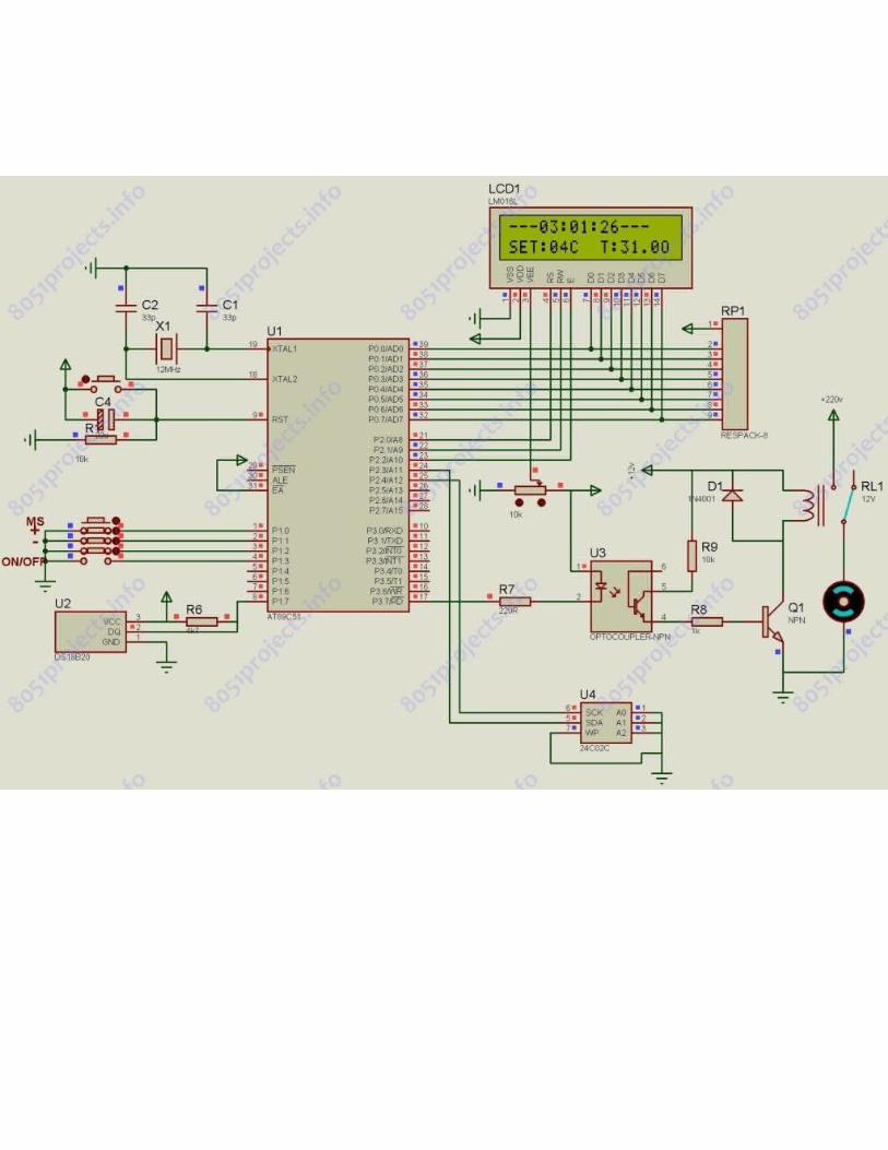
Interfacing GPS with graphic LCD using 8051 microcontrollerThe gps output is connected to P3.0, i.e RXD pin of AT89S52.
The LCD pin diagram is given below
LCD parallel data to P2Data 1/0 Select command pin to P0.7Read 1 / Write 0 to P0.6Chip select 1(Master) to P0.4Chip select 2(slave) to P0.5Backlight to P0.3
Two keys are connected toPage Up key to P0.0Page Down key to P0.1


http://www.8051projects.info/resources/zigbee-based-wireless-weather-monitoring-system.101/

http://www.8051projects.info/resources/zigbee-based-dc-motor-control-from-pc.98/

http://www.8051projects.info/resources/rfid-based-device-control-and-authentication-using-8051.12/

http://www.8051projects.info/resources/temperature-controller-using-ds1820-and-lcd-display.7/


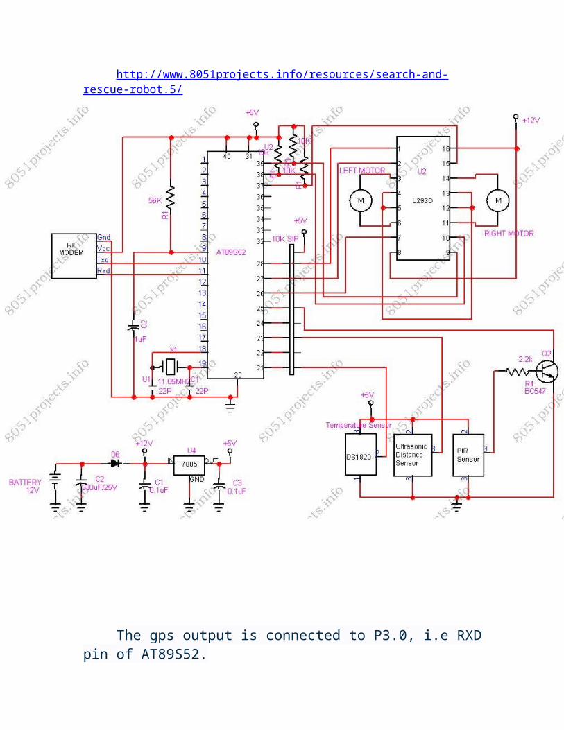
http://www.8051projects.info/resources/search-and-rescue-robot.5/
The gps output is connected to P3.0, i.e RXD pin of AT89S52.
The LCD pin diagram is given below

LCD parallel data to P2Data 1/0 Select command pin to P0.7Read 1 / Write 0 to P0.6Chip select 1(Master) to P0.4Chip select 2(slave) to P0.5Backlight to P0.3
Two keys are connected toPage Up key to P0.0Page Down key to P0.1 .
http://www.8051projects.info/resources/8051-c-code-for-interfacing-gps.191/

What is GPSAbout GPS technology
Overview
Discussion1. Global Positioning System (GPS) is a network of satellites that
continuously transmit coded information, which makes it possible to precisely identify locations on earth by measuring distance from the satellites.
GPS stands for Global Positioning System, and refers to a group of U.S.Department of Defense satellites constantly circling the earth. The satellites transmit very low power radio signals allowing anyone with a GPS receiver to determine their location on Earth. This remarkable system was not cheap to build, costing the U.S. billions of dollars. Ongoing maintenance, including the launch of replacement satellites, adds to the cost of the system.
It would not only tell us where we are in position coordinates (latitude/longitude), but would even display our location on an electronic map along with cities, streets and more. These designers originally had a military application in mind. GPS receivers would aid navigation, troop deployment and artillery fire (among other applications). Fortunately, an executive decree in the 1980s made GPS available for civilian use also. Now everyone gets to enjoy the benefits of GPS! The capability is almost unlimited.
APPLICATIONS OF GPS
GPS has a variety of applications on land, at sea and in the air. Basically, GPS allows you to record or create locations from places on the earth and help you navigate to and from those spots. GPS can be used everywhere except where it's impossible to receive the signal such as inside buildings; in caves, parking garages, and other subterranean locations; and underwater. The most common airborne applications include navigation by general aviation and commercial aircraft. At sea, GPS is typically used for navigation by recreational boaters and fishing enthusiasts. Land-based applications are more diverse. The scientific community uses GPS for its precision timing capability and a myriad of other applications. Surveyors use GPS for an increasing portion of their work. GPS offers an incredible cost savings by drastically reducing setup time at the survey site. It also provides amazing accuracy. Basic survey units can offer accuracies down to one meter. More expensive systems can provide accuracies
Recreational uses of GPS are almost as varied as the number of recreational sports available. GPS is becoming increasingly popular among hikers, hunters, snowmobilers, mountain bikers, and cross- country skiers, just to name a few. If you are involved in an activity or sport where you need to keep track of where you are, find your way to a specified location, or know what direction and how fast you're going, you can benefit from the Global

Positioning System.
GPS is rapidly becoming commonplace in automobiles as well. Some basic systems are already in place, providing emergency roadside assistance at the push of a button (by transmitting your current position to a dispatch center). More sophisticated systems can show the vehicle's position on an electronic map display, allowing drivers to keep track of where they are and look up street addresses, restaurants, hotels and other destinations. Some systems can even automatically create a route and give turn-by-turn directions to a designated location.
You don't have to be a rocket scientist to learn how GPS works. All you need is a little background knowledge plus the desire to explore and understand the world of GPS. Don't let terms like "pseudo-random", "anti-spoofing" and "P Code" frighten you. Let's dig right in and start to become familiar with the best navigation tool to come along since the invention of the compass.
GPS ReceiverAbout GPS Receiver and how it works.
Overview
Discussion

1.The main function of the GPS receiver is to receive the exact position of the receiver located on the Earth's surface. For this purpose,24 satellites are revolving around the outer space. The GPS receiver receives the data in NMEA format. The data includes the information regarding the latitudinal and longitudinal data, number of satellites, Greenwich Mean Time etc.
The 3 Segments of GPS
The NAVSTAR system (the acronym for Navigation Satellite Timing and Ranging, the official U.S. Department of Defense name for GPS) consists of a space segment (the satellites), a control segment (the round stations), and a user segment (you and your GPS receiver).Now let's take the three parts of the system and discuss them in more detail. Then we'll look more closely at how GPS works.

The Space Segment
The space segment, which consists of at least 24 satellites (21 active plus 3 operating spares) is the heart of the system. The satellites are in what's called a "high orbit" about 12,000 miles above the Earth's surface. Operating at such a high altitude allows the signals to cover a greater area.
The satellites are arranged in their orbits so a GPS receiver on earth can always receive from at least four of them at any given time. The satellites are traveling at speeds of 7,000 miles an hour, which allows them to circle the earth once every 12 hours. They are powered by solar energy and are built to last about 10 years. If the solar energy fails (eclipses, etc.), they have backup batteries on board to keep them running. They also have small rocket boosters to keep them flying in the correct path.
Each satellite transmits low power radio signals on several frequencies (designated L1, L2, etc.). Civilian GPS receivers "listen" on the L1 frequency of 1575.42 MHz in the UHF band. The signal travels "line of sight", meaning it will pass through clouds, glass and plastic, but will not go through most solid objects such as buildings and mountains.
To give you some idea of where the L1 signal is on the radio dial, your

favorite FM radio station broadcasts on a frequency somewhere between 88 and 108 MHz (and sounds much better!). The satellite signals are also very low power signals, on the order of 20-50 watts. Your local FM radio station is around 100,000 watts. Imagine trying to listen to a 50-watt radio station transmitting from 12,000 miles away! That's why it's important to have a clear view of the sky when using your GPS.
L1 contains two "pseudorandom" (a complex pattern of digital code) signals, the Protected (P) code and the Coarse/Acquisition (C/A) code. Each satellite transmits a unique code, allowing the GPS receiver to identify the signals. "Anti-spoofing" refers to the scrambling of the P code in order to prevent its unauthorized access. The P code is also called the "P (Y)" or"Y" code.
The main purpose of these coded signals is to allow for calculating the travel time from the satellite to the GPS receiver on the Earth. This traveltime is also called the Time of Arrival. The travel time multiplied by the speed of light equals the satellite range (distance from the satellite to the GPS receiver). The Navigation Message (the information the satellites transmit to a receiver) contains the satellite orbital and clock information and general system status messages and an ionospheric delay model. The satellite signals are timed using highly accurate atomic clocks.The Control Segment
The "control" segment does what its name implies - it "controls" the GPS satellites by tracking them and then providing them with corrected orbital and clock (time) information. There are five control stations located around the world - four unmanned monitoring stations and one "master control station". The four unmanned receiving stations constantly receive data from the satellites and then send that information to the master control station. The master control station "corrects" the satellite data and, together with two other antenna sites, sends ("uplinks") the information to the GPS satellites.
The User Segment
The user segment simply consists of you and your GPS receiver. As mentioned previously, the user segment consists of boaters, pilots, hikers, hunters, the military and anyone else who wants to know where they are, where they have been or where they are going.
How does it Work?
The GPS receiver has to know two things if it's going to do its job. It has to know WHERE the satellites are (location) and how FAR AWAY they are (distance). Let's first look at how the GPS receiver knows where the satellites are located in space. The GPS receiver picks up two kinds of coded information from the satellites. One type of information, called "almanac" data, contains the approximate positions (locations) of the satellites. This data is continuously transmitted and stored in the memory of the GPS

receiver so it knows the orbits of the satellites and where each satellite is supposed to be. The almanac data is periodically updated with new information as the satellites move around.
Any satellite can travel slightly out of orbit, so the ground monitor stations keep track of the satellite orbits, altitude, location, and speed. The ground stations send the orbital data to the master control station, which inturn sends corrected data up to the satellites. This corrected and exact position data is called the "ephemeris" (pronounced: i-'fe-me-res) data, which is valid for about four to six hours, and is transmitted in the coded information to the GPS receiver. So, having received the almanac and ephemeris data, the GPS receiver knows the position (location) of the satellites at all times.
Time is of the Essence
Even though the GPS receiver knows the precise location of the satellites in space, it still needs to know how far away the satellites are (the distance) so it can determine its position on Earth. There is a simple formula that tells the receiver how far it is from each satellite.
Calculating position
Your distance from a given satellite object equals the velocity of the transmitted signal multiplied by the time it takes the signal to reach you (Velocity x Travel Time = Distance).
GPS works on the principle, called "Time of Arrival". the same basic formula to determine distance, the receiver already knows the velocity. It's the speed of a radio wave - 186,000 miles per second (the speed of light), less any delay as the signal travels through the Earth's atmosphere. Now the GPS receiver needs to determine the time part of the formula. The answer lies in the coded signals the satellites transmit. The transmitted code is called "pseudo-random code" because it looks like a noise signal. When a satellite is generating the pseudo-random code, the GPS receiver is generating the same code and tries to match it up to the satellite's code. The receiver then compares the two codes to determine how much it needs to delay (or shift) its code to match the satellite code. This delay time (shift) is multiplied by the speed of light to get the distance.
Your GPS receiver clock does not keep the time as precisely as the satellite clocks. Putting an atomic clock in your GPS receiver would make it much larger and far too expensive! So each distance measurement needs to be corrected to account for the GPS receiver's internal clock error. For this reason, the range measurement is referred to as a "pseudo-range". To determine position using pseudo-range data, a minimum of four satellites must be tracked and the four fixes must be recomputed until the clock error disappears.
Now that we have both satellite location and distance, the receiver can

determine a position. Let's say we are 11,000 miles from one satellite. Our location would be somewhere on an imaginary sphere that has the satellite in the center with a radius of 11,000 miles. Then let's say we are 12,000 miles from another satellite. The second sphere would intersect the first sphere to create a common circle. If we add a third satellite, at a distance of 13,000 miles, we now have two common points where the three spheres intersect. Even though there are two possible positions, they differ greatly in latitude/longitude position AND altitude. To determine which of the two common points your actual position is, you'll need to enter your approximate altitude into the GPS receiver. This will allow the receiver to calculate a two-dimensional position (latitude, longitude). However, by adding a fourth satellite, the receiver can deter-mine your three-dimensional position (latitude, longitude, altitude). Let's say our distance from a fourth satellite is 10,000 miles. We now have a fourth sphere intersecting the first three spheres at one common point.
The unit stores data about where the satellites are located at any given time. This data is called the almanac. Sometimes when the GPS unit is not turned on for a length of time, the almanac can get outdated or "cold". When the GPS receiver is "cold", it could take longer to acquire satellites. A receiver is considered "warm" when the data has been collected from the satellites within the last four to six hours. When you're looking for a GPS unit to buy, you may see "cold" and "warm" acquisition time specifications. If the time it takes the GPS unit to lock on to the signals and calculate a position is important to you, be sure to check the acquisition times. Once the GPS has locked onto enough satellites to calculate a position, you are ready to begin navigating! Most units will display a position page or a page showing your position on a map (map screen) that will assist you in your navigation.
GPS Receiver Technology
Most modern GPS receivers are a parallel multi-channel design. Older single-channel designs were once popular, but were limited in their ability to continuously receive signals in the toughest environments - such as under heavy tree cover. Parallel receivers typically have from between five and 12 receiver circuits, each devoted to one particular satellite signal, so strong locks can be maintained on all the satellites at all times. Parallel-channel receivers are quick to lock onto satellites when first turned on and they are unequaled in their ability to receive the satellite signals even in difficult conditions such as dense foliage or urban settings with tall buildings.

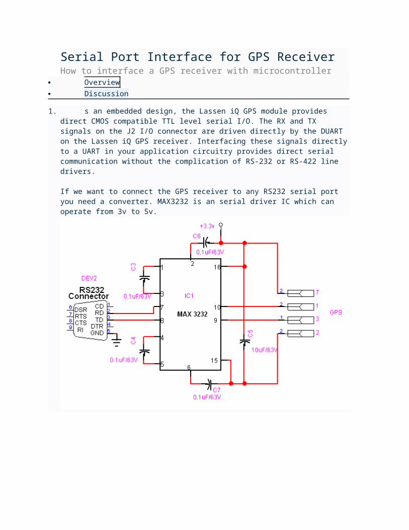
Serial Port Interface for GPS ReceiverHow to interface a GPS receiver with microcontroller
Overview
Discussion
1. s an embedded design, the Lassen iQ GPS module provides direct CMOS compatible TTL level serial I/O. The RX and TX signals on the J2 I/O connector are driven directly by the DUART on the Lassen iQ GPS receiver. Interfacing these signals directly to a UART in your application circuitry provides direct serial communication without the complication of RS-232 or RS-422 line drivers.
If we want to connect the GPS receiver to any RS232 serial port you need a converter. MAX3232 is an serial driver IC which can operate from 3v to 5v.

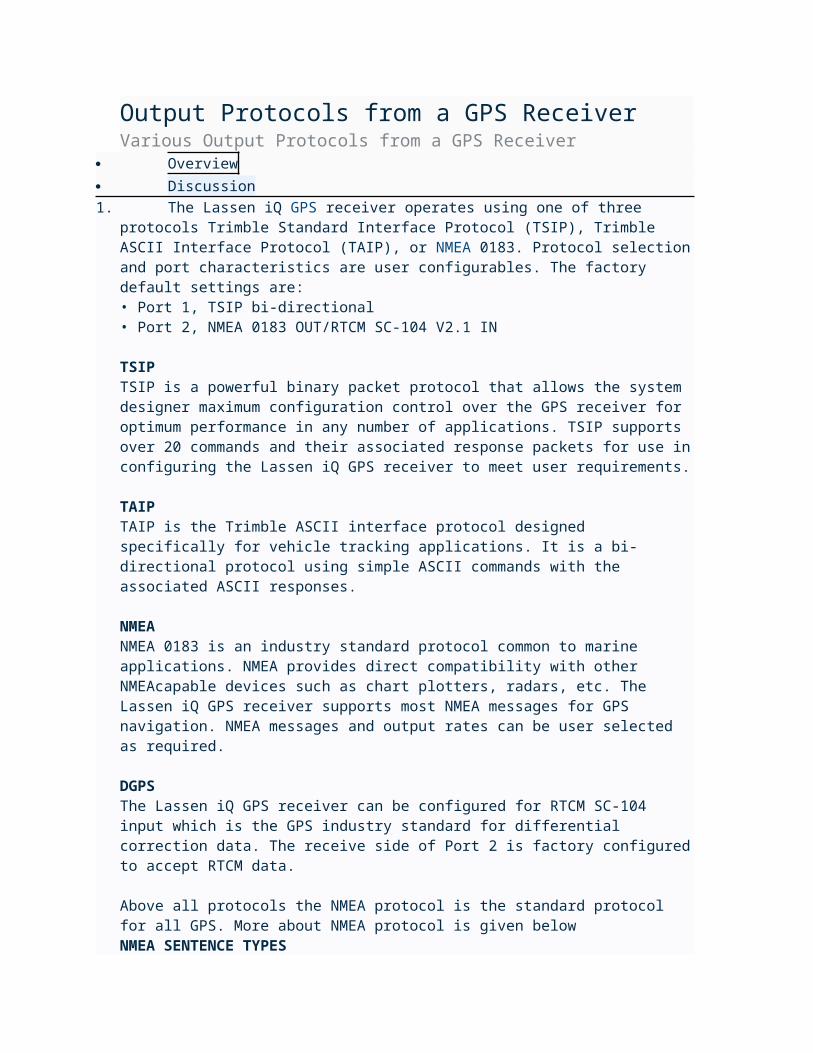
Output Protocols from a GPS ReceiverVarious Output Protocols from a GPS Receiver
Overview
Discussion1. The Lassen iQ GPS receiver operates using one of three protocols
Trimble Standard Interface Protocol (TSIP), Trimble ASCII Interface Protocol (TAIP), or NMEA 0183. Protocol selection and port characteristics are user configurables. The factory default settings are:• Port 1, TSIP bi-directional• Port 2, NMEA 0183 OUT/RTCM SC-104 V2.1 IN
TSIPTSIP is a powerful binary packet protocol that allows the system designer maximum configuration control over the GPS receiver for optimum performance in any number of applications. TSIP supports over 20 commands and their associated response packets for use in configuring the Lassen iQ GPS receiver to meet user requirements.
TAIPTAIP is the Trimble ASCII interface protocol designed specifically for vehicle tracking applications. It is a bi-directional protocol using simple ASCII commands with the associated ASCII responses.
NMEANMEA 0183 is an industry standard protocol common to marine applications. NMEA provides direct compatibility with other NMEAcapable devices such as chart plotters, radars, etc. The Lassen iQ GPS receiver supports most NMEA messages for GPS navigation. NMEA messages and output rates can be user selected as required.
DGPSThe Lassen iQ GPS receiver can be configured for RTCM SC-104 input which is the GPS industry standard for differential correction data. The receive side of Port 2 is factory configured to accept RTCM data.
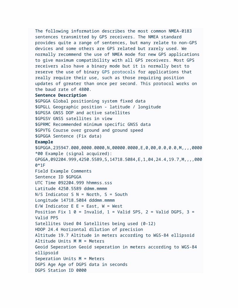
Above all protocols the NMEA protocol is the standard protocol for all GPS. More about NMEA protocol is given belowNMEA SENTENCE TYPESThe following information describes the most common NMEA-0183 sentences transmitted by GPS receivers. The NMEA standard provides quite a range of sentences, but many relate to non-GPS devices and some others are GPS related but rarely used. We normally recommend the use of NMEA mode for new GPS applications to give maximum compatibility with all GPS receivers. Most GPS receivers also have a binary mode but it is normally best to reserve the use of binary GPS protocols for applications that really require their use, such as those requiring position updates of greater than once per second. This protocol works on the baud rate of 4800.Sentence Description$GPGGA Global positioning system fixed data
$GPGLL Geographic position - latitude / longitude$GPGSA GNSS DOP and active satellites$GPGSV GNSS satellites in view$GPRMC Recommended minimum specific GNSS data$GPVTG Course over ground and ground speed$GPGGA Sentence (Fix data)Example$GPGGA,235947.000,0000.0000,N,00000.0000,E,0,00,0.0,0.0,M,,,,0000*00 Example (signal acquired):GPGGA,092204.999,4250.5589,S,14718.5084,E,1,04,24.4,19.7,M,,,,0000*1FField Example CommentsSentence ID $GPGGA UTC Time 092204.999 hhmmss.sssLatitude 4250.5589 ddmm.mmmmN/S Indicator S N = North, S = SouthLongitude 14718.5084 dddmm.mmmmE/W Indicator E E = East, W = WestPosition Fix 1 0 = Invalid, 1 = Valid SPS, 2 = Valid DGPS, 3 = Valid PPSSatellites Used 04 Satellites being used (0-12)HDOP 24.4 Horizontal dilution of precisionAltitude 19.7 Altitude in meters according to WGS-84 ellipsoidAltitude Units M M = MetersGeoid Seperation Geoid seperation in meters according to WGS-84 ellipsoidSeperation Units M = MetersDGPS Age Age of DGPS data in secondsDGPS Station ID 0000 Checksum *1F Terminator CR/LF

Circuit Diagram & Program to Interface a GPS Receiver with AT89S51Circuit Diagram & Program to Interface a GPS Receiver with AT89S51
Overview
Discussion
1.
Bascom 8051 Program
Code:
$baud = 9600
$crystal = 11059200 Config Lcd = 16 * 2 Config Lcdpin = Pin , Db4 = P0.2 , Db5 = P0.3 , Db6 = P0.4 , Db7 = P0.5 , E = P0.1 , Rs = P0.0 Rem with the config lcdpin statement you can override the compiler settings '$GPGGA,012211.83,4119.6171,N,07730.0636,W,1,03,3.6,00522,M,,,,*36 'GPS Time, Latitude, Longitude Display 'set up variables Dim Gps As Byte , X As Byte , Lont(6) As Byte , Latt(6) As ByteDim Lat As Byte , Latmin As Byte , Latfrac As Byte , Latns As ByteDim Lon As Byte , Lonmin As Byte , Lonfrac As Byte , Lonew As ByteDim Timt(6) As ByteDim Hours As Byte , Mins As Byte , Secs As Byte HomeClsCursor Off Looploop:HomeUpperlineStartloop: Gps = Waitkey()If Gps <> "$" Then Goto Startloop Gps = Waitkey()If Gps <> "G" Then Goto Startloop Gps = Waitkey()If Gps <> "P" Then Goto Startloop Gps = Waitkey()If Gps <> "G" Then Goto Startloop Gps = Waitkey()If Gps <> "G" Then Goto Startloop Gps = Waitkey()If Gps <> "A" Then Goto Startloop Gps = Waitkey()If Gps <> "," Then Goto Startloop

For X = 1 To 6 Gps = Waitkey() Lcd Chr(gps) ; Timt(x) = Gps If X = 2 Then Lcd ":"; If X = 4 Then Lcd ":";Next X Timlop:Gps = Waitkey()If Gps = "," Then Goto GetlatGoto Timlop Getlat:LowerlineFor X = 1 To 6Getlat1: Gps = Waitkey() If Gps = "." Then Goto Getlat1 Latt(x) = Gps Lcd Chr(gps);Next X Getlat2:Gps = Waitkey()If Gps <> "," Then Goto Getlat2Gps = Waitkey()Lcd Chr(gps) ; " ";Latns = GpsGps = Waitkey()Gps = Waitkey() For X = 1 To 6Getlon: Gps = Waitkey() If Gps = "." Then Goto Getlon Lont(x) = Gps Lcd Chr(gps);Next XGetlon1:Gps = Waitkey()If Gps <> "," Then Goto Getlon1Gps = Waitkey()Lcd Chr(gps);Gps = Waitkey()Gps = Waitkey()Gps = Waitkey()Locate 1 , 11Lcd "Sat:"Gps = Waitkey()Lcd Chr(gps);Gps = Waitkey()

Lcd Chr(gps); Goto Looploop
Device control through SMS using SIM300 and AT89S52Control your home appliances through SMS
Overview
Discussion1. In this article we are going to explain how to control electrical devices
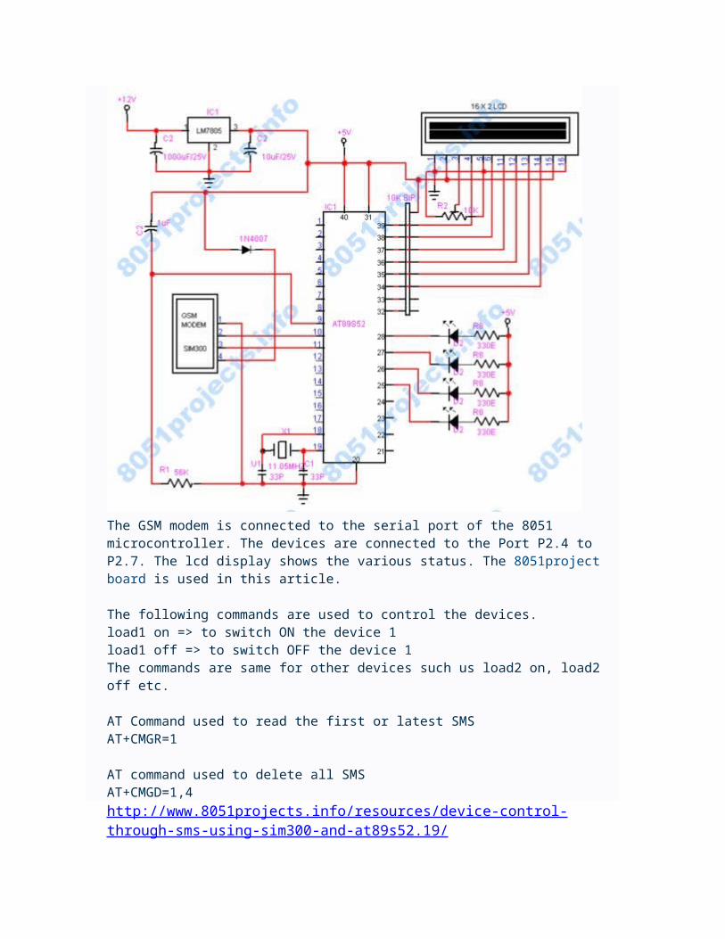
through SMS using a GSM modem and AT89S52 microcontroller. We are using SIM300 gsm modem with TTL output. You can control 4 devices with this code in this article, which can be extended more with similar drivers. We can shown LEDs as the output devices. You can easily connect relays in the place of the LED using a relay driver IC ULN2003.
Circuit Diagram
The GSM modem is connected to the serial port of the 8051 microcontroller. The devices are connected to the Port P2.4 to P2.7. The lcd display shows the various status. The 8051project board is used in this article.

The following commands are used to control the devices.load1 on => to switch ON the device 1load1 off => to switch OFF the device 1The commands are same for other devices such us load2 on, load2 off etc.
AT Command used to read the first or latest SMSAT+CMGR=1
AT command used to delete all SMSAT+CMGD=1,4http://www.8051projects.info/resources/device-control-through-sms-using-sim300-and-at89s52.19/

We can get the location without using the GPS. An SIM300 module can get the tower location by using AT commands, so we can create a simple tracking system.
AT Command to get the tower locationAT+CSCB=0,"50","0-9"
Simple 8051 code to display the tower location on the LCD display.
The hardware is implemented using 8051 project board.

http://www.8051projects.info/resources/circuit-diagram-for-interfacing-sim300-gsm-modem-to-at89s52.15/

Send and Receive SMS through GSM modemAT Commands to initialize the gsm modemAT => Its just to wake the modem.ATE0 => Echo offAT+CMGF=1 => Enable text mode to send smsAT+CNMI=1,1,0,0,0 => Disable new message indication OFF
AT Commands to Send/Receive SMSAT+CMGF=1 =>Make SIM300 to text modeAT+CMGR=1 =>To read the first message AT+CMGS="mobile number" =>To send SMSAT+CMGD=1 => To delete first messageAT+CMGD=1,4 =>To delete all messages
AT Commands to make/receive callATDmobilenumber => To make a callATH => To Hang/disconnect a callATA =>To receive a callATE0 => Enable caller ID http://www.8051projects.info/resources/send-and-receive-sms-through-gsm-modem.16/
INCLUDE reg_51.pdf INPUT EQU P3.2 ; Port3,Bit2 is used as input. The demodulated signal ; with active low level is connected to this pin RB0 EQU 000H ; Select Register Bank 0RB1 EQU 008H ; Select Register Bank 1 ...poke to PSW to use DSEG ; This is internal data memoryORG 20H ; Bit adressable memory FLAGS: DS 1CONTROL BIT FLAGS.0 ; toggles with every new keystrokeNEW BIT FLAGS.1 ; Bit set when a new command has been received COMMAND: DS 1 ; Received command byteSUBAD: DS 1 ; Device subaddressTOGGLE: DS 1 ;Toggle every bitANS: DS 1 ;ADDR: DS 1STACK: DS 1 ; Stack begins hereCSEG ; Code begins here;---------==========----------==========---------=========---------; PROCESSOR INTERRUPT AND RESET VECTORS;---------==========----------==========---------=========--------- ORG 00H ; Reset JMP MAIN ORG 0003H ; External Interrupt0 JMP RECEIVE

;---------==========----------==========---------=========---------; ---------==========----------==========---------=========---------; Interrupt 0 routine; ---------==========----------==========---------=========---------RECEIVE: CPL P2.2 MOV 2,#235 ; Time Loop (3/4 bit time) DJNZ 2,$ ; Waste Time to sync second bit MOV 2,#235 ; Time Loop (3/4 bit time) Djnz 2,$ ; Waste Time to sync second bit Mov 2,#134 ; Time Loop (3/4 bit time) Djnz 2,$ ; Waste Time to sync second bit clr a mov r6,#07h pol1: mov c,Input rlc a Mov 2,#235 ; Waste time for next BIT Djnz 2,$ Mov 2,#235 ; Time Loop (3/4 bit time) Djnz 2,$ ; Waste Time to sync second bit Mov 2,#235 ; Time Loop (3/4 bit time) Djnz 2,$ ; Waste Time to sync second bit Mov 2,#105 ; Time Loop (3/4 bit time) Djnz 2,$ ; Waste Time to sync second bit djnz r6,pol1 MOV SUBAD,A mov r6,#06hpol2: mov c,Input rlc a Mov 2,#235 ; Waste time for next BIT Djnz 2,$ Mov 2,#235 ; Time Loop (3/4 bit time) Djnz 2,$ ; Waste Time to sync second bit Mov 2,#235 ; Time Loop (3/4 bit time) Djnz 2,$ ; Waste Time to sync second bit Mov 2,#105 ; Time Loop (3/4 bit time) Djnz 2,$ ; Waste Time to sync second bit djnz r6,pol2 Mov COMMAND,A ; Save Command at IRData memory MOV A,SUBAD MOV ADDR,A ANL A,#0FH MOV SUBAD,A CJNE A,#03H,ZXC1 MOV A,COMMAND CPL A MOV COMMAND,A AJMP ASZZXC1: MOV A,SUBAD
CJNE A,#00H,ANSS AJMP ASZ ASZ: MOV A,ADDR ANL A,#20H MOV TOGGLE,A CJNE A,ANS,ANSS AJMP WARANSS: JMP ANS1 WAR: MOV A,COMMAND CJNE A,#01H,DSP1 CPL P0.0DSP1: CJNE A,#02H,DSP2 CPL P0.1DSP2: CJNE A,#03H,DSP3 CPL P0.2DSP3: CJNE A,#04H,DSP4 CPL P0.3DSP4: CJNE A,#05H,DSP5 CPL P0.4DSP5: CJNE A,#06H,DSP6 CPL P0.5DSP6: CJNE A,#07H,DSP7 CPL P0.6DSP7: CJNE A,#08H,DSP8 CPL P0.7DSP8: CJNE A,#0CH,DSP9 MOV P0,#0FFHDSP9: MOV ANS,TOGGLE MOV A,ANS CPL ACC.5 MOV ANS,A SETB NEW ; Set flag to indicate the new command ;################################################################ ANS1: RETI ; ---------==========----------==========---------=========---------; Main routine. Program execution starts here.; ---------==========----------==========---------=========---------MAIN: MOV SP,#60H SETB EX0 ; Enable external Interrupt0 CLR IT0 ; triggered by a high to low transition SETB EA; /* Enable global interrupt */ MOV ANS,#00H ;clear temp toggle bit

CLR NEW LOO: JNB NEW,LOO CLR NEW AJMP LOO END
http://www.8051projects.info/resources/infrared-receiver-interfacing.36/
#include <at89x52.h>#include "lcd.h" main( ){ LCD_init(); LCD_row1(); LCD_puts("Hello World"); LCD_row2(); LCD_puts("Good Morning"); while (1);}#define LCD_en P3_1#define LCD_rs P3_0#define LCD_DELAY 2000 /* Delay for 1 ms */#define LCD_clear() LCD_command(0x1) /* Clear display LCD */#define LCD_origin() LCD_command(0x2) /* Set to origin LCD */#define LCD_row1() LCD_command(0x80) /* Begin at Line 1 */#define LCD_row2() LCD_command(0xC0) /* Begin at Line 2 *//**************************************************** Prototype(s) ****************************************************/void LCD_delay(unsigned char ms);void LCD_enable();void LCD_command(unsigned char command);void LCD_putc(unsigned char ascii);void LCD_puts(unsigned char *lcd_string);void LCD_init(); /**************************************************** Sources ****************************************************/void LCD_delay(unsigned char ms){ unsigned char n; unsigned int i; for (n=0; n<ms; n++) { for (i=0; i<LCD_DELAY; i++); /* For 1 ms */ } } void LCD_enable(){ LCD_en = 0; /* Clear bit P2.4 */ LCD_delay(1); LCD_en = 1; /* Set bit P2.4 */} void LCD_command(unsigned char command){ LCD_rs = 0; /* Clear bit P2.5 */ P2 = (P2 & 0xF0)|((command>>4) & 0x0F); LCD_enable(); P2 = (P2 & 0xF0)|(command & 0x0F); LCD_enable();

LCD_delay(1);} void LCD_putc(unsigned char ascii){ LCD_rs = 1; /* Set bit P2.5 */ P2 = (P2 & 0xF0)|((ascii>>4) & 0x0F); LCD_enable(); P2 = (P2 & 0xF0)|(ascii & 0x0F); LCD_enable(); LCD_delay(1);} void LCD_puts(unsigned char *lcd_string){ while (*lcd_string) { LCD_putc(*lcd_string++); }} void LCD_init(){ LCD_en = 1; /* Set bit P2.4 */ LCD_rs = 0; /* Clear bit P2.5 */ LCD_command(0x33); LCD_command(0x32); LCD_command(0x28); LCD_command(0x0C); LCD_command(0x06); LCD_command(0x01); /* Clear */ LCD_delay(256);}

Interfacing LCD to PC Parallel PortInterfacing the LCD module to PC parallel port
Overview
Discussion
1. General:Character (alphanumeric) type LCD modules are most commonly driven froman embedded microcontroller. It is sometimes desirable to be able to drive this type of module directly from a PC. This would allow the module to be tested or a demonstration or simulation to be set up quickly and with a minimum of engineering. This application note describes a method of driving an LCD character module fromthe printer port of a PC with minimal external hardware.
The printer port of a PC:There are at least three versions of printer ports available now on PCs.SPP (Standard Parallel Port)EPP (Enhanced Parallel Port)ECP (Extended Capability Port)To make this design as universal as possible it will be based on the least capable and oldest specification, SPP.
Figure illustrates the pinout of the parallel port and the register that controls each pin. The connector drawing is the female connector on the PC. To maintain compatibility with all versions of parallelports now available on PCs only the output capabilities are used in this example. The LCD module provides a busy flag that can be read to control the timing of data and command writes. The timing of all data and command transfers is know and this is used to time the transfer of data and commands to the LCD in software.
The parallel port has 12 buffered TTL output pins which are latched and can be written under program control using the processor’s Out instruction. The port also has input pins but they are not used in this example.

Hardware Description:The suggested circuit is quite simple. The display, data and control lines are connected to the printer port lines as shown in Table 1 and the schematic. The read/write (RW) line is tied low to fix the display in the write mode. The Enable (E) and the Register Select (RS) lines are tied to two of the parallel port control lines. Most parallel ports have active or passive pull-ups on these lines, but not all. To be universal 10k pull-up resistors are shown on these two lines. Contrast control is provided by a 10k pot. DC power for the LCD and the back light, if installed, must be provided externally. LCDs require very little power to operate, typically less than 5mA. The outputs on the parallel port are able to source up to 10mA, so it is possible to power the LCD from one of the output lines. This doesn’t apply to the back light which requires from 50mA to 300mA. One of the control lines can be used for this purpose as shown.
in Figure. This also has the advantage of being able to shut off the display via software. A 1 on this line turns the display on and a 0 turns it off.The type of cable used to connect the parallel port to the LCD will determine the maximumlength of the cable. Ribbon cable, for instance, should not be used in lengths over 3’. A shielded, twisted pair cable can be used up to 50’. The quickest and most economical way of building a shielded, twisted pair in small quantities is to use a commercial printer cable of the desired length and cut off the connector that would normally connect to the printer. The wires are then prepared and connected to the LCD module.
Software:Most contemporary PCs support 3 parallel ports at addresses 278/378/3BC. All values are in hex. Usually only one port is physically installed and in most systems it is at address 378 and is assigned to LPT1. An output instruction

to the base address of the port, 278/378/3BC, will latch data to the data port of the LCD as shown below.
BIT 7 6 5 4 3 2 1 0PIN 9 8 7 6 5 4 3 2LCD D7 D6 D5 D4 D3 D2 D1 D0An output instruction to the base address of the port +2, 27A/37A/3BE,will latch the lower 4 bits of the data bus to the control pins of the LCD. Only two of these signals are needed to control most LCD character modules. The exception is the 40 character by 4 line modules. These modules have two controllers on them and have an extra enable line. The port pin C1 can be used for this 2nd enable on the 40x4 modules. The bits are assigned to the LCD as shown below.
ProgramExample:The following sample code is written in Microsoft C and will display a message on a two line by 16 character LCD module. It can be used as a guide in working with larger or smaller modules as it has all of the elements needed. A total of 80 characters is writen to the display which is the maximum any LCD character display with one controller can store. This program will thus work for a 1, 2 or 4 line display although only two lines will display characters on a 4 line module.A more sophisticated way of writing characters is to issue a SET DD RAMADDRESS command for each line to be written. Check with the data sheet for the particular module you are using to set the DD RAM address and line lengths. The program first initializes the display and then sends the two lines of data. The displayed message should read:>>8051projects<<ABC abc 123,!@$?Code:
Code:
/* Sample Software to display a message on a 16 x2 character LCD module/* from a parallel port of a PC#include <time.h>#include <conio.h>#include <string.h>#define PORTADDRESS 0x378 /*Enter port address here */#define DATA PORTADDRESS+0 /*LCD data port */#define CONTROL PORTADDRESS+2 /*LCD control port */void main (void){/* Total of 40 characters including spaces in each line of string */char string[] = {”>>8051projects<< ““ABC abc 123,!@$? “};char init[10];int count;int len;init[0] = 0x0F; /* Initialize display */

init[1] = 0x01; /* Clear display */init[2] = 0x38; /* Dual line 8 bits */_out(CONTROL, _inp(CONTROL) & 0xDF); /* Reset control port */_out(CONTROL, _inp(CONTROL) | 0x08); /*Set RS *//* Initialization routine */for (count = 0; count <= 2; count++){_out(DATA, init[count]);_out(CONTROL,_inp(CONTROL) | 0x01; /*Set Enable */delay(20);_out(CONTROL,_inp(CONTROL) & 0xFE; /*Reset Enable */delay(20);}_out(CONTROL, _inp(CONTROL) & 0xF7);/*Reset RS *//* Output the message */len = strlen(string);for (count = 0; count < len; count++){_out(DATA, string[count]);_out(CONTROL,_inp(CONTROL) | 0x01; /*Set Enable */delay(2);_out(CONTROL,_inp(CONTROL) & 0xFE); /*Reset Enable */delay(2);}}

Implementing a 4 bit Counter using an 8051 and Interfacing it to an LCDImplementing a 4 bit Counter using an 8051 and Interfacing it to an LCD
Overview
Discussion
1. The program will be used to control a simple 4-bit up-down counter, capable of counting from 0 to 15. At each step the count should be displayed in decimal format on the LCD.
he 4 bit counter has the following functionality:The counter has the following input pins :a. Reset : when high resets the counter dataout to ``0000''b. Updown : decides whether the counter counts up or down.c. Load : makes the counter count from the 4 bit input Dataind. Datain : which is a 4 bit input countThe counter has a 4 bit Dataout to reflect the count.The count has to be sent to the LCD and displayed in decimal format.
Code:
#pragma SMALL DB OE#include#include "io.h" /* P0, P1, P2 and P3 are predefined port names and are bit addressable */ sbit reset = P0^4; /* bit 4 of Port 0 */sbit up_down = P0^5;

sbit load = P0^6;sbit Start_LCD = P0^7; /* bit 7 of Port 3 */ /* Delay function */void delay() { int i, j; for(i=0; i<1000; i++) for(j=0; j<100; j++) i = i + 0;} /* Function to output the decimal value of the count on the LCD */void PrintInt(unsigned char i) { char ch[4]; /* Write code to convert the count to a string value and use the PrintString function provided in io.c */ PrintString(ch);} void main(void) { unsigned char count = 0; InitIO(); /* Initialize the LCD */ while (1) { if (Start_LCD == 1) { ClearScreen(); PrintString("Ready..."); delay(); } else if (reset == 1) { /* Output 0 on the LCD */ } else if (load == 1) { /* Output the current value of Datain on the LCD */ } else { /* Check the Up/Down pin for 1 or 0 count up or down accordingly. Display each value on the LCD */ } }}

Interfacing Serial Port (RS232) with 8051 microcontrollerInterfacing Serial Port with 8051 microcontroller
Overview
Discussion
1. Program to establish a serial communication link between the PC and the 8051
Description:Serial communication is often used either to control or to receive data from an embedded microprocessor. Serial communication is a form of I/O in which the bits of a byte begin transferred appear one after the other in a timed sequence on a single wire. Serial communication has become the standard for intercomputer communication. In this Project, we'll try to build a serial link between 8051 and PC using RS232.
Using the Serial Port8051 provides a transmit channel and a receive channel of serial communication. The transmit data pin (TXD) is specified at P3.1, and the receive data pin (RXD) is at P3.0. The serial signals provided on these pins are TTL signal levels and must be boosted and inverted through a suitable converter(Max232) to comply with RS232 standard.All modes are controlled through SCON, the Serial CONtrol register. The SCON bits are defined as SM0, SM1, SM2, REN, TB8, RB8, TI, RI from MSB to LSB. The timers are controlled using TMOD, the Timer MODe register, and TCON, the Timer CONtrol register.
Use Hyper Terminal at PC side to send/receive Data
Code:
#pragma SMALL DB OE#include <reg51.h> unsigned char ReceiveSerial() {

unsigned char c; TMOD = 0x20; /* configure timer for the correct baud rate */ TH1 = 0xe6; /* 1200 bps for 12 MHz clock */ TCON = 0x00; /* Set timer to not running */ SCON = 0x50; /* Set Serial IO to receive and normal mode */ TR1 = 1; /* start timer to Receive */ while( (SCON & 0x01) == 0 ) /* wait for receive data */; c = SBUF; return c;} void SendSerial(unsigned char c) { /* initialize..set values for TMOD, TH1 and TCON */ /* set the Tx interrupt in SCON to indicate sending data */ /* start timer */ /* write character to SBUF */ /* wait for completion of sent data */} void main(void) { unsigned char c; while( 1 ) { /* Use ReceiveSerial to read in a character 'c' */ /* Do some computation on 'c' */ /* Send the result using SendSerial() */ }}

Implementing a Calculator Using Peripherals Like a Keypad and LCDImplementing a Calculator Using Peripherals Like a Keypad and LCD
Overview
Discussion1. In this Project, you will build a simple calculator using the keypad as
an input and the LCD as an output peripheral. After debugging and testing your program, you will have to burn the compiled program to a standalone 8051 chip at the end of this lab.
Description:Keypads are often used as a primary input device for embedded microcontrollers. The keypads actually consist of a number of switches, connected in a row/column arrangement as shown in Fig.
In order for the microcontroller to scan the keypad, it outputs a nibble to force one (only one) of the columns low and then reads the rows to see if any buttons in that column have been pressed. The rows are pulled up by the internal weak pull-ups in the 8051 ports. Consequently, as long as no buttons are pressed, the microcontroller sees a logic high on each of the pins attached to the keypad rows. The nibble driven onto the columns always contains only a single 0. The only way the microcontroller can find a 0 on any row pin is for the keypad button to be pressed that connects the column set to 0 to a row. The controller knows which column is at a 0-level and which row reads 0, allowing it to determine which key is pressed. For

the keypad, the pins from left to right are: R1, R2, R3, R4, C1, C2, C3, C4.
Code:/* To implement a integer calculator using a keypad and LCD */ #pragma SMALL DB OE#include <reg51.h>#include "io.h" /* The functions to initialize and control the LCD are assumed to be in the file io.c */ /* Function to output the decimal value of the result on the LCD */void PrintInt(int i) { . . .} /* Routine to scan the key pressed */unsigned char key_scan(){ unsigned char i, j, temp1, temp2; while( 1 ) /* keep waiting for a key to be pressed */ for(i=0; i<4; i++) { /* Set each row to 0 */ P1 = 0xff & ~(1<<i); /* Scan each column to see which key was pressed */ for (j=4; j<8; j++) { /* Code to determine the position of the key which was pressed */ /* return(position) */

} }} void main() { /* You can have a conversion table to convert the key position into a valid number which indicates the operator or operand value. For eg: the numbers 0 to 9 are valid operands and 100 to 103 denote addition, subtraction, multiplication and division respectively */ char conv_table[] = { 1, 2, 3, 100 /* add */, 4, 5, 6, 101 /* sub */, 7, 8, 9, 102 /* mul */, -1, 0, -1, 103 /* div */ }; char num1, num2, op; int result; InitIO(); while(1) { ClearScreen(); /* read num1 */ GotoXY(0, 0); PrintString("num1 : "); do { num1 = conv_table[key_scan()]; } while( num1 < 0 || num1 > 9 ); /* read a valid operation */ GotoXY(0, 0); PrintString("op : "); do { op = conv_table[key_scan()]; } while( op < 100 ); /* read num2 */ GotoXY(0, 0); PrintString("num2 : "); do { num2 = conv_table[key_scan()]; }

while( num2 < 0 || num2 > 9 ); /* compute result */ if( op == 100 ) { /* Add numbers and display result on the LCD */ } else if( op == 101 ) { . . . . /* Continue similarly for other operations */ } }}