interface requirement specification - capanina october 2004, updated version on 9th october 2006...
TRANSCRIPT

29th October 2004, updated version on 9th October 2006 FP6-IST-2003-506745 CAPANINA Page 1 of 36
FP6-IST-2003-506745 CAPANINA
Deliverable Number D8
Interface Requirement Specification for a HAP free-space optical crosslink terminal
Document Number CAP-D08-WP34-CSAG-PUB-02
Contractual Date of Delivery to the CEC 1st November 2004
Actual Date of Delivery to the CEC 29th October 2004, updated version on 9th October 2006
Author(s): Thomas Dreischer (CSAG)
Participant(s) (partner short names): CSAG
Editor (Internal reviewer) Myles Capstick (UOY)
Workpackage: WP3.4
Estimated person months 12
Security (PUBlic, CONfidential, REStricted)
PUB
Nature R - Report
CEC Version 1.2
Total number of pages (including cover): 36
Abstract:
This document compiles physical interface requirements for a HAP free-space optical crosslink terminal that are considered generic because at present they cannot be related to a dedicated stratospheric flight platform.
The HAP-interface requirements for an optical beam steering unit concentrate on information from accredited literature, like high altitude platform alignment characteristics described in HeliNET reference documentation, or like background radiation levels in the optical bandwidth from reference literature or electrical and EMC interface specifications from the MIL-handbook.
Optical transmission in the stratospheric channel has not been explored and measured, yet. Therefore, models have been built that simulate temporal fading of optical beams in a stratospheric transmission channel, based on measurements in atmosphere. Similar, a micro-vibration model was established based on measurement data from a Zeppelin airship, as no information was yet available on expected vibration levels of stratospheric blimps.
All models have been integrated, together with interface information based on literature, into a system simulation that describes an optical crosslink between two blimps in stratosphere. The system simulation architecture bases on hardware experience in the development of prototype optical terminals for inter-satellite crosslinks in space. It was adapted for stratospheric cross links. The outcome of the system simulation showed that state-of-the-art technology can be used to realise an optical HAP crosslink terminal based on the interface requirement specifications given in this document, including a contingency margin on critical parameters.
This document has been updated to include further information which was not available earlier.
Keyword list: optical beam steering, attitude, stratospheric fading, optical background, vibration

Thomas Dreischer (CSAG) FP6-IST-2003-506745 CAPANINA Page 2 of 36
DOCUMENT HISTORY
Date Revision Comment Author / Editor Affiliation
29th Oct 2004
01 First Issue Thomas Dreischer CSAG
20th July 2006 02
Update including measurement data from Trial 2 in 2 Annexes and Update of temperature requirements No. R-D08-3.6-3-A,T-SY, R-D08-3.6-4-A,T-SY, R-D08-3.6-5-A,T-SY (all w.r.t environment) update of pressure requirement No. R-D08-3.6-7-A,T,I-UN (environment)
Thomas Dreischer CSAG
Document Approval (CEC Deliverables only)
Date of approval
Revision Role of approver Approver Affiliation
29th Oct 2004
01 Editor (Internal reviewer) Myles Capstick UOY
29th Oct 2004
01 On behalf of Scientific Board David Grace UOY
9th Oct 2006
02 On behalf of Scientific Board David Grace UOY
Thomas Dreischer (CSAG) FP6-IST-2003-506745 CAPANINA Page 3 of 36
EXECUTIVE SUMMARY
The current document compiles all boundary conditions, parameters and data required to analyse an optical crosslink link through the stratosphere and to design an optical inter-HAP crosslink terminal for stratospheric application.
As this document is written during a very early state of development, not all parameters described in this interface specification could be based on existing data in tables or from measurement results. Therefore, several assumptions had to be made on certain parameters like, for instance, optical propagation characteristics in a horizontal stratospheric transmission channel or the microvibration spectra and attitude characteristics expected on a blimp platform. Such parameters have mostly been assessed by similarity, for instance from optical atmospheric propagation measurements or from vibration characteristics of existing airship platforms.
At a later stage, the data compiled in this document could be complemented by a performance specification and an interface requirements document, dedicated to a specific high altitude platform.
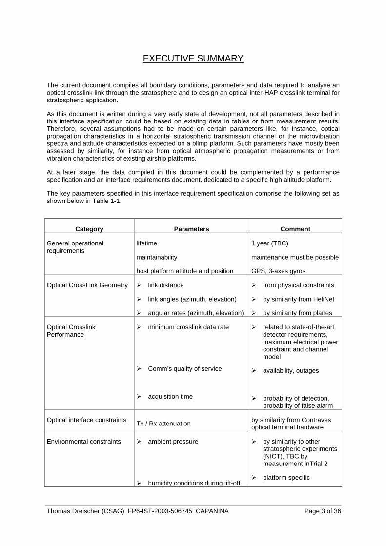
The key parameters specified in this interface requirement specification comprise the following set as shown below in Table 1-1.
Category Parameters Comment
General operational requirements
lifetime
maintainability
host platform attitude and position
1 year (TBC)
maintenance must be possible
GPS, 3-axes gyros
Optical CrossLink Geometry Ø link distance
Ø link angles (azimuth, elevation)
Ø angular rates (azimuth, elevation)
Ø from physical constraints
Ø by similarity from HeliNet
Ø by similarity from planes
Optical Crosslink Performance
Ø minimum crosslink data rate
Ø Comm’s quality of service
Ø acquisition time
Ø related to state-of-the-art detector requirements, maximum electrical power constraint and channel model
Ø availability, outages
Ø probability of detection, probability of false alarm
Optical interface constraints Tx / Rx attenuation by similarity from Contraves optical terminal hardware
Environmental constraints Ø ambient pressure
Ø humidity conditions during lift-off
Ø by similarity to other stratospheric experiments (NICT), TBC by measurement inTrial 2
Ø platform specific
Thomas Dreischer (CSAG) FP6-IST-2003-506745 CAPANINA Page 4 of 36
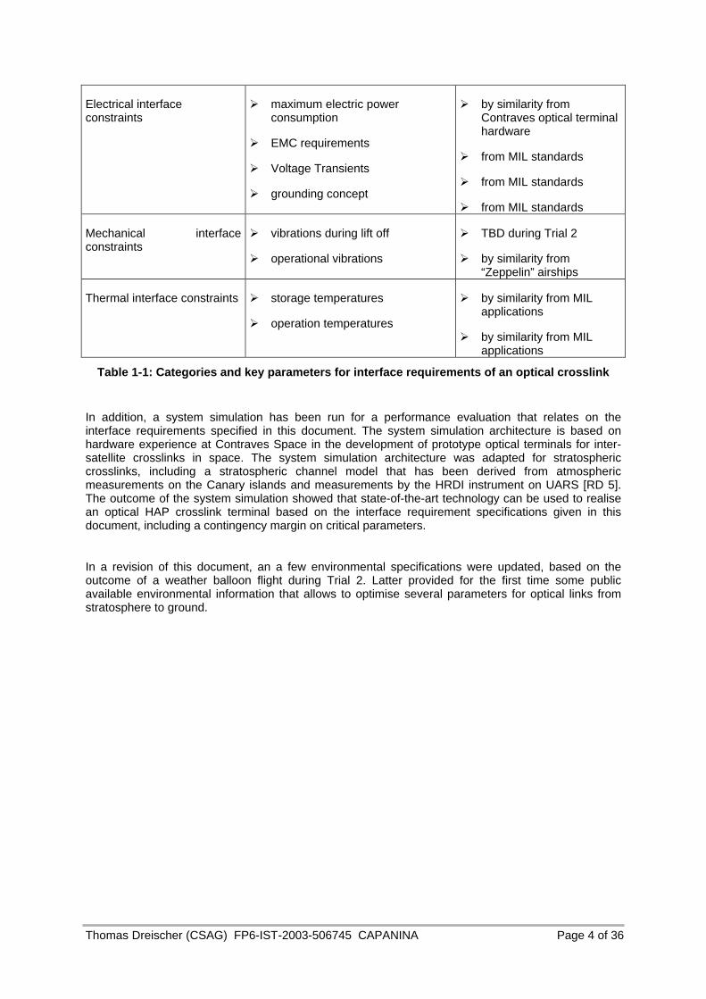
Electrical interface constraints
Ø maximum electric power consumption
Ø EMC requirements
Ø Voltage Transients
Ø grounding concept
Ø by similarity from Contraves optical terminal hardware
Ø from MIL standards
Ø from MIL standards
Ø from MIL standards
Mechanical interface constraints
Ø vibrations during lift off
Ø operational vibrations
Ø TBD during Trial 2
Ø by similarity from “Zeppelin” airships
Thermal interface constraints Ø storage temperatures
Ø operation temperatures
Ø by similarity from MIL applications
Ø by similarity from MIL applications
Table 1-1: Categories and key parameters for interface requirements of an optical crosslink
In addition, a system simulation has been run for a performance evaluation that relates on the interface requirements specified in this document. The system simulation architecture is based on hardware experience at Contraves Space in the development of prototype optical terminals for inter-satellite crosslinks in space. The system simulation architecture was adapted for stratospheric crosslinks, including a stratospheric channel model that has been derived from atmospheric measurements on the Canary islands and measurements by the HRDI instrument on UARS [RD 5]. The outcome of the system simulation showed that state-of-the-art technology can be used to realise an optical HAP crosslink terminal based on the interface requirement specifications given in this document, including a contingency margin on critical parameters.
In a revision of this document, an a few environmental specifications were updated, based on the outcome of a weather balloon flight during Trial 2. Latter provided for the first time some public available environmental information that allows to optimise several parameters for optical links from stratosphere to ground.
Thomas Dreischer (CSAG) FP6-IST-2003-506745 CAPANINA Page 5 of 36
TABLE OF CONTENTS
1. DEFINITIONS, ABBREVIATIONS, AND SYMBOLS .................................................... 10 1.1 Definitions................................................................................................................................. 10 1.1.1 Document/Documentation ..................................................................................................... 10 1.1.2 Configuration.......................................................................................................................... 10 1.1.3 Form, Fit, Function................................................................................................................. 10 1.1.4 Derating ................................................................................................................................. 10 1.1.5 Fail Safe................................................................................................................................. 10 1.1.6 Requirement Tracking ........................................................................................................... 10
2. APPLICABLE AND REFERENCE DOCUMENTS ........................................................ 11 2.1 General..................................................................................................................................... 11 2.1.1 Military Documents ................................................................................................................ 11
2.2 Order of Precedence ................................................................................................................ 11 2.3 Reference Documents.............................................................................................................. 11
3. INTERFACE REQUIREMENTS.................................................................................... 12 3.1 General..................................................................................................................................... 12 3.2 On-board information on host platform position and attitude ................................................... 12 3.3 Performance Characteristics .................................................................................................... 13 3.4 Derating and margins ............................................................................................................... 15 3.4.1 General .................................................................................................................................. 15 3.4.2 Electrical Derating.................................................................................................................. 15 3.4.3 Mechanical Derating .............................................................................................................. 15 3.4.4 Thermal derating.................................................................................................................... 16
3.5 Interface and Physical Dimensions .......................................................................................... 17 3.5.1 Electrical ................................................................................................................................ 17
3.5.1.1 Interface requirements....................................................................................................................17 3.5.1.2 Electrical design.............................................................................................................................18
3.5.2 Optical.................................................................................................................................... 19 3.5.3 Mechanical............................................................................................................................. 22
3.6 Environmental Considerations.................................................................................................. 23 3.6.1 Operating Temperature Range.............................................................................................. 23 3.6.2 Ambient Pressure .................................................................................................................. 24
3.6.2.1 Lift-off Environment ......................................................................................................................24 3.6.2.2 Stratospheric Environment.............................................................................................................24
3.6.3 Acceleration ........................................................................................................................... 24 3.6.4 Vibration................................................................................................................................. 24
3.6.4.1 Launch vibration ............................................................................................................................24 3.6.4.2 Microvibration ...............................................................................................................................24
3.6.5 Atmospheric channel fading .................................................................................................. 25 3.6.5.1 Fade duration .................................................................................................................................26 3.6.5.2 Fade probability .............................................................................................................................26

Thomas Dreischer (CSAG) FP6-IST-2003-506745 CAPANINA Page 6 of 36
3.6.5.3 Fade repetition frequency...............................................................................................................26 3.6.6 Radiation................................................................................................................................ 26
3.6.6.1 Total dose.......................................................................................................................................26 3.6.6.2 Particle Environment......................................................................................................................27
3.6.6.2.1 Single Event Latchup ..............................................................................................................27 3.6.6.2.2 Single Event Upset ..................................................................................................................27
3.6.7 Humidity ................................................................................................................................. 27 3.6.8 Electromagnetic Compatibility................................................................................................ 27
4. SUMMARY AND CONCLUSIONS................................................................................ 33
5. ANNEX A: ENVIRONMENTAL DATA MEASURED PRIOR TO TRIAL 2 EXECUTION 34
6. ANNEX B: GEOMETRIC LINK DATA MEASURED DURING TRIAL 2 ........................ 35
7. ANNEX C: FRIED’S PARAMETER MEASURED DURING TRIAL 2 ............................ 36

Thomas Dreischer (CSAG) FP6-IST-2003-506745 CAPANINA Page 7 of 36
LIST OF FIGURES
Figure 3-1: Graze height versus crosslink distance for different HAP altitudes........................... 13 Figure 3-2 : Spherical coordinates used in the present study ........................................................ 14 Figure 3-3: Worst case radiance from a blimp’s cover along line-of-sight, in 1 nm filter BW ..... 20 Figure 3-4: FFT of Zeppelin microaccelerations, selection of test cases in RD 5......................... 25 Figure 3-5: Conducted emissions; power lines, current ................................................................. 29 Figure 3-6: Conducted emissions – voltage spikes ......................................................................... 29 Figure 3-7: Radiated emissions – E-field narrow band.................................................................... 31 Figure 3-8: Radiated emissions – E-field broad band...................................................................... 31 Figure 3-9: Radiated emissions – H field........................................................................................... 32 Figure 5-1:Capanina Trial 2 environmental data from a test flight, recorded one day before
actual flight (courtesy by University of York, UK)..................................................................... 34 Figure 6-1: Capanina Trial 2 measurement data from actual flight with a weather balloon:
recorded data are angles, range, altitude, range velocity (courtesy by DLR, Germany)....................................................................................................................................... 35
Figure 3-5: CAPANINA measurements of Fried’s parameter on actual flight day of Trial (courtesy by DLR, Germany) ....................................................................................................... 36

Thomas Dreischer (CSAG) FP6-IST-2003-506745 CAPANINA Page 8 of 36
LIST OF TABLES
Table 1-1:Categories and key parameters for interface requirements of an optical crosslink...... 4 Table 1-2: List of acronyms .................................................................................................................. 9 Table 3-1: Nomenclature of spherical coordinates used in the present document...................... 14 Table 3-2: Mechanical design margins for the ISLFE terminal ....................................................... 16 Table 3-3 : Received background flux from diffuse reflected sunlight in 1nm optical filter BW. 21 Table 3-4: Clear Blue Sky spectral radiance at sea level , view angle 45 deg ............................... 21 Table 3-5: Solar radiance in 1nm optical BW.................................................................................... 22 Table 3-6:Attenuation characteristics for 35mm Tx/135mm Rx aperture diameter, 1550nm
wavelength.................................................................................................................................... 26

Thomas Dreischer (CSAG) FP6-IST-2003-506745 CAPANINA Page 9 of 36
LIST OF ACRONYMS
AC Alternating Current
AO Adaptive Optics
BOL Beginning of Life
BSU Beam Steering Unit
BW Band Width
CSAG Contraves Space AG Zurich
DC Direct Current
EU Electronics Unit
EOL End of Life
ESD Electro-Static Discharge
FoS Factor of Safety
ICD Interface Control Document
IUH Inter-unit harness
OH Optical Head
PSD Power spectral density
RMS Root Mean Square
TBC To be confirmed
TBD To be defined
us/div microsecond per division
WCA Worst case analysis
°C Degrees Celsius
% percent
Table 1-2: List of acronyms
Thomas Dreischer (CSAG) FP6-IST-2003-506745 CAPANINA Page 10 of 36
1. DEFINITIONS, ABBREVIATIONS, AND SYMBOLS
1.1 Definitions
1.1.1 Document/Documentation
The specifications, drawings, lists, standards, pamphlets, reports, or other information relating to the design, acquisition, manufacture, test, or inspection of items under the contract.
1.1.2 Configuration
The functional and physical characteristics of existing or planned hardware, firmware, software, or a combination thereof as set forth in technical documentation and ultimately achieved in a product.
1.1.3 Form, Fit, Function
a) Form The shape, size, dimensions, mass, weight, and other visual parameters which uniquely characterise an item. For software, form denotes the language and media.
b) Fit The ability of an item to physically interface or interconnect with or become an integral part of another item.
c) Function The action or actions which an item is designed to perform.
1.1.4 Derating
Derating is the reduction of electrical, thermal, and mechanical stresses applied to a part in order to decrease the degradation rate and prolong the expected life of the part.
1.1.5 Fail Safe
A design feature that ensures that the system remains safe or in the event of a failure, will cause the system to revert to a state which will not cause a mishap.
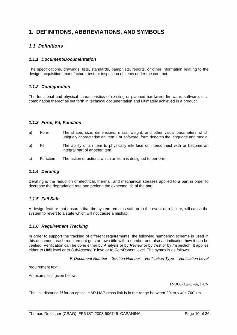
1.1.6 Requirement Tracking
In order to support the tracking of different requirements, the following numbering scheme is used in this document: each requirement gets an own title with a number and also an indication how it can be verified. Verification can be done either by Analysis or by Review or by Test or by Inspection. It applies either to UNit level or to SubAssemblY leve or to ComPonent level. The syntax is as follows:
R-Document Number – Section Number – Verification Type – Verification Level
requirement text...
An example is given below:
R-D08-3.2-1 –A,T-UN
The link distance ld for an optical HAP-HAP cross link is in the range between 20km ≤ ld ≤ 700 km

Thomas Dreischer (CSAG) FP6-IST-2003-506745 CAPANINA Page 11 of 36
2. Applicable and Reference Documents
2.1 General
The following documents of the exact issue and/or revision shown form a part of this Specification to the extent specified herein. Where no issue is shown the latest issue is applicable.
2.1.1 Military Documents
AD 1 MIL–HDBK-217 Reliability Prediction of Electronic Equipment
AD 2 MIL–STD–975M Standard Parts List for Flight and Mission Essential Ground Support Equipment
AD 3 MIL-STD-2000 Standard Requirements for Soldered Electrical and Electronic Assemblies
AD 4 MIL-STD-1686 Electrostatic Discharge Control Program for Protection of Electrical and Electronic Parts, Assemblies and Equipment (excluding electrically initiated explosive devices)
AD 4 MIL-HDBK-263 Electrostatic Discharge Control Handbook for Protection of Electrical and Electronic Parts, Assemblies and Equipment (excluding electrically initiated explosive devices)
2.2 Order of Precedence In the event of conflict between the text of this document and applicable documents, the following order of precedence shall apply:
1. This document
2. Applicable documents
2.3 Reference Documents The following documents are for reference/guideline only.
RD 1 HE-079-WP5-UNY-SP-01, Issue 1 Outline System Specification for the Broadband Application (Helinet Project)
RD 2 HE-051-T6-UNY-RP-01, Issue 1 Stratospheric Platform Antenna Design Study (HeliNet Project)
RD 3 Radio Corporation of America (RCA): “Electro Optics Handbook, a compendium of useful information and technical data”, 1968, pp. 7-8 and 7-11
RD 4 Optical Channels, Fibers Clouds Water, and the Atmosphere, S. Karp et. al., Plenum Press, New York, 1988, section 1.4
RD 5 The High Resolution Doppler Imager, University of Michigan, http://hrdi.engin.umich.edu/index.html
RD 6 Upper Atmosphere Research Satellite (UARS) Project Science Office Page, http://umpgal.gsfc.nasa.gov/www_root/homepage/uars-science.html
RD 7 ZEPPELIN Luftschifftechnik GmbH, “Vibration measurements for the Installation of Supplemental Equipment in the LZ N07 Gondola”, Germany Sept 2001
Thomas Dreischer (CSAG) FP6-IST-2003-506745 CAPANINA Page 12 of 36
3. Interface Requirements
3.1 General
The general design and interface requirements defined here for the optical crosslink terminal have been established in the absence of a defined high altitude platform (HAP). These requirements are therefore only applicable as a guide to the constraints and requirements considered in the design of the terminal. A general design and interface requirement specification (GDIR) shall be elaborated in co-operation with a HAP supplier for a mission in which an optical HAP crosslink terminal shall be a payload element.
R-D08-3.1-1 -A,T-UN
The lifetime of an optical crosslink terminal for high altitude platforms shall at least be 1 year (TBC).
R-D08-3.1-2 -A,T-UN
The design of the optical crosslink terminal for high altitude platforms shall allow maintenance operations. A modular approach with inter-changeability of parts and subsystems is required.
R-D08-3.1-3 -A,T-UN
The optical crosslink is considered to provide non-time critical service. However, the time to establish an optical link shall be minimised and not exceed 2 minutes from the moment of execution command.
3.2 On-board information on host platform position and attitude
Initial information on high altitude host platform characteristics has been taken from RD 1 and RD 2. The host platform shall provide a data interface to the optical terminal with information about
current position
current time (UTC)
current attitude
time of link initialisation
for both, the host platform and the partner HAP that is defined as dedicated communication target.
R-D08-3.2-1 -A,T-UN
The host platform shall provide GPS/Galileo type of positioning information in geocentric coordinates, with a position knowledge accuracy of ±100m in all three axes.
R-D08-3.2-2 -A,T-UN
The host platform shall provide (gyro-based) attitude knowledge with an accuracy of at least 0.17 deg per axis.
R-D08-3.2-2 -A,T-UN
The host platform shall provide attitude velocity information with an accuracy of at least 1.0 deg/sec deg per axis.

Thomas Dreischer (CSAG) FP6-IST-2003-506745 CAPANINA Page 13 of 36
3.3 Performance Characteristics
The optical terminal performance shall ensure to work according to the optical link characteristics specified below.
R-D08-3.3-1 -A,T-UN
The optical HAP-HAP cross link terminal shall work at altitudes between 17km and 22km.
R-D08-3.3-2 -A,T-UN
The link distance ld for an optical HAP-HAP cross link is specified in the range between 20km(TBC) and 700 km.
The maximum limitation on distances is related to maximum line-of-sight at the given minimum altitude range, with an additional constraint to stay above a maximum measured Cirrus cloud level of 13km, shown below in Figure 3-1.
Figure 3-1: Graze height versus crosslink distance for different HAP altitudes
The minimum link distance for stratospheric transmission modelling has arbitrarily been set to 20km. Concerning the beam steering unit, some subsystem constraints are related to a minimum link distance. Such constraints are the angular speed and angular range of the coarse pointing unit to compensate for sudden inter-HAP HAP angular motion. Another reason for a lower boundary could be a minimum required HAP distance for which a HAP crosslink network becomes superior to- or as attractive as the installation of a ground based fibre network. This lower link distance boundary value could be further reduced, its nominal value will also have to take into account appropriate constellations and inter HAP spacings. Therefore, the minimum link distance is still TBC.
Thomas Dreischer (CSAG) FP6-IST-2003-506745 CAPANINA Page 14 of 36
R-D08-3.3-3 -A,T-UN
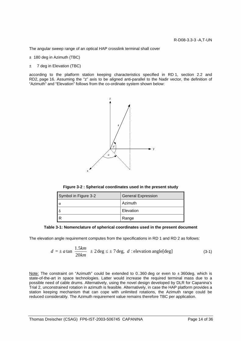
The angular sweep range of an optical HAP crosslink terminal shall cover
± 180 deg in Azimuth (TBC)
± 7 deg in Elevation (TBC)
according to the platform station keeping characteristics specified in RD 1, section 2.2 and RD2, page 16. Assuming the “z” axis to be aligned anti-parallel to the Nadir vector, the definition of “Azimuth” and “Elevation” follows from the co-ordinate system shown below:
z
y
x
r
α
δ
Figure 3-2 : Spherical coordinates used in the present study
Symbol in Figure 3-2 General Expression
α Azimuth
δ Elevation
R Range
Table 3-1: Nomenclature of spherical coordinates used in the present document
The elevation angle requirement computes from the specifications in RD 1 and RD 2 as follows:
angle[deg]elevation :deg,7deg220
5.1tan δδ ±≤±
±=
kmkm
a (3-1)
Note: The constraint on “Azimuth” could be extended to 0..360 deg or even to ± 360deg, which is state-of-the-art in space technologies. Latter would increase the required terminal mass due to a possible need of cable drums. Alternatively, using the novel design developed by DLR for Capanina’s Trial 2, unconstrained rotation in azimuth is feasible. Alternatively, in case the HAP platform provides a station keeping mechanism that can cope with unlimited rotations, the Azimuth range could be reduced considerably. The Azimuth requirement value remains therefore TBC per application.

Thomas Dreischer (CSAG) FP6-IST-2003-506745 CAPANINA Page 15 of 36
R-D08-3.3-4 -A,T-UN
The angular speed of an optical HAP crosslink terminal shall cover
± 10 deg/sec in Azimuth (TBC)
± 10 deg/sec in Elevation (TBC)
The data given above depend on
Ø the HAP station keeping and attitude control characteristics.
Ø the link distance.
Ø the search procedure during initial acquisition of the partner terminal.
Because this requirement is rather platform dependent, it can only be given as TBC engineering estimate.
R-D08-3.3-5 -A,T-UN
The minimum data rate of a bi-directional optical HAP-HAP crosslink shall stay ≥ 155 Mbps (TBC) during all environmental conditions like daytime/night-time, strong or weak turbulence conditions.
R-D08-3.3-6 -A,T-UN
The comm’s quality of service shall provide a BEP <10^-9 at the given data rate.
R-D08-3.3-6 -A,T-UN
The optical crosslink availability shall be 99.9% of all link cases.
3.4 Derating and margins
3.4.1 General
R-D08-3.4-1-A,T-UN,SY,CP
All parts and materials shall be derated in order to increase the margin of safety between the operating stress level and the actual failure level of the part.
3.4.2 Electrical Derating
R-D08-3.4-2-A,T-UN,SY,CP
Appendix A of MIL-STD-975M [AD 2] shall be used as the guidelines for derating of electrical parts and materials; further derating shall be applied if needed in order to meet the requirements of this specification.
3.4.3 Mechanical Derating
R-D08-3.4-3-A,T-UN,SY,CP
Adequate margins shall be incorporated into the design through the use of appropriate factors of safety (FoS). The FoS given in Table 3-2 shall be applied to the flight limit load to size and test the mechanical components. It is mandatory that all the parts still demonstrate positive margins of safety.

Thomas Dreischer (CSAG) FP6-IST-2003-506745 CAPANINA Page 16 of 36
Table 3-2: Mechanical design margins for a HAP crosslink terminal
Item Yield Ultimate Buckling Remarks
Conventional Materials 1.25 1.50 2.00 If qualified by test
Conventional Materials 1.50 2.00 2.00 If qualified by analysis
Unconventional Materials 1.50 2.00 2.00 If qualified by test
Unconventional Materials 2.00 3.00 2.00 If qualified by analysis
Inserts and Joints 1.50 2.00 n/a If qualified by test
Inserts and Joints 2.00 3.00 n/a If qualified by analysis
Note: Pressure vessels and pressurised components are not covered by these definitions. The safety factors required vary with materials, type of tests performed, size etc. and will be defined on a case by case basis.
3.4.4 Thermal derating
A margin has also to be applied to the temperature to ensure that the given values are not exceeded during the life of the unit. The uncertainty of the temperature prediction resulting from the modelling assumptions shall also be accounted for in the margin philosophy. The temperature predictions should include margins to the design acceptance temperature that will give the required reliability over the unit life.
R-D08-3.4-4-A,T-UN,SY,CP
The margin philosophy is as follow:
Ø To maintain a margin of at least 5°C between predicted temperatures and the design operating temperatures (acceptance temperatures);
Ø To maintain a margin of at least 10°C between design operating temperatures and the qualification temperatures;
Ø To maintain a margin of at least 5°C between qualification temperatures and the survival temperatures.

Thomas Dreischer (CSAG) FP6-IST-2003-506745 CAPANINA Page 17 of 36
3.5 Interface and Physical Dimensions
3.5.1 Electrical
3.5.1.1 Interface requirements
R-D08-3.5-1-A,T-UN
The optical crosslink Terminal shall be designed to operate from a DC primary power input (main bus) with the following characteristics at its primary power input connections:
Voltage: 28V ± 8V DC
Voltage ripple & noise: 126 dBµV @ 30 Hz ≤ f < 5 kHz
126 dBµV-20 dB/decade @ 5 kHz ≤ f < 50 kHz
Voltage Transients: 50%, -150% of nominal line voltage (duration 1 msec, repeated every 10s)
R-D08-3.5-2 -A,T-UN
The overall average power consumption of an optical HAP crosslink terminal shall remain ≤60 W (TBC), assuming the minimum data rate performance of the optical crosslink as specified in section 3.3. This figure has been estimated on the basis of the available HAP on-board power consumption as described in RD 1, section 2.2.
Signal interface requirements shall be as defined in the appropriate sections of the equipment specifications. Noise immunity with both level and time discrimination shall be designed into digital interface circuits. Analogue and digital interfaces shall be designed to respond only to intentional frequency bandwidths.
R-D08-3.5-3 -A,T-UN
Transmission bandwidths shall be limited to the extent possible. Transient protection shall be implemented on unit inputs and outputs. High frequency interfaces (> 1MHz TBC) are exempt from the single point ground system where the use of coax cables is required.
R-D08-3.5-4 -A,T-UN
The units shall isolate each primary power wire from their equipment chassis by more than 1 MΩ shunted by a capacitance of less than 50 nF.
Each secondary power wire shall be isolated from each primary power wire by more than 1 MΩ shunted by a capacitance of less than 50nF.
R-D08-3.5-5 -A,T-UN
Provision for intentional external grounding of the secondary power single point grounds shall be implemented. These single ground point connections shall use the shortest possible path to the chassis structure, to reduce the series inductance. Where a single power converter supplies several pieces of equipment, the secondary power reference shall be single point grounded within the equipment containing the converter. All other equipment shall maintain a DC isolation not less than 1 MΩ between the power input leads and their chassis.

Thomas Dreischer (CSAG) FP6-IST-2003-506745 CAPANINA Page 18 of 36
3.5.1.2 Electrical design
R-D08-3.5- 6-A,T,I-UN
The grounding concept for the optical crosslink Terminal shall be based on a distributed single point grounding scheme, with the objective of using the HAP structure as an equipotential reference plane (ground). It shall prevent DC or low frequency AC currents from flowing in this ground reference plane. The primary power distribution shall have a dedicated single ground reference to structure at the source side for primary power. Each secondary power distribution network shall be isolated from the primary power, and all secondary power networks shall have their own single point ground reference. The grounding connection from secondary power to chassis is not allowed where an isolated secondary voltage is referenced to the primary power return (e.g. for control purposes).
The design of the secondary circuit grounding shall ensure that ground loops are prevented. All loads must return power through dedicated lines. The design of the electrical interfaces between different units shall ensure electrical isolation and common mode rejection. The structure shall not be used as a return current path.
The signal interface grounding for each type of signal interface shall be as defined in the interface requirements section of the appropriate equipment specifications. The signal interfaces definitions shall take account of the need to provide appropriate isolation of the signal interfaces in order to prevent ground loops and to ensure the appropriate conditions for meeting the EMC requirements.
R-D08-3.5- 7-A,T,I-UN
The housings of the optical crosslink Terminal units (optical head and electronics unit) shall each provide a bonding lug with a contact area greater than 1cm2 (TBC). The bonding lug contact area shall be provided with a highly conductive and corrosion resistant surface finish. The position of the bonding lug on the equipment’s housing shall be close to the mechanical interface plane, such that the length of a bond strap from the equipment to the HAP structure will be minimised.
The housings of the optical crosslink Terminal units shall form an unbroken conductive shield via continuous contact between conductive mating surfaces on the equipment walls. The DC resistance between each wall of an equipment, and the equipment’s bonding lug shall not exceed 2.5mΩ. The maximum dimensions of apertures in the equipment housings shall be chosen so that electric fields are sufficiently attenuated for compliance with the radiated emissions and susceptibility (EMC) requirements [AD 22].
Connector shells shall have a conductive finish and shall be electrically bonded to the equipment housing. The DC resistance between each connector shell of an equipment, and the equipment’s bonding lug shall not exceed 5 mΩ.
R-D08-3.5-8 -T,I-UN
For the harness design the optical crosslink Terminal wiring shall be classified into the following classes:
Ø Class 1: Power harness and non – sensitive signals (e.g. digital, ON/OFF signals)
Ø Class 2: Sensitive signals
And the following requirements shall apply:
Wires of the same class shall be assembled into one bundle. Where cables of different classes must be routed along a common path the distance between classes shall be more than 5 cm. Where bundles of different classes must cross each other, the crossing angle shall, as far as possible, be at 90° to each other.
This classification will be maintained through the box connectors. Therefore, only one class may be routed through one connector. The interface circuits shall be arranged such that circuits connected to wires in one category are separated from wires in another category.
Further details shall be specified in a Inter-Unit Harness Specification.
Thomas Dreischer (CSAG) FP6-IST-2003-506745 CAPANINA Page 19 of 36
R-3.5-9-A,T,I-UN
Wiring shall be twisted to reduce magnetic pick – up and emissions.
Active wires shall always be twisted around their return wires.
Where several lines share a return line, the whole bundle shall be twisted with its common return wire.
The number of twists per unit length shall be determined by the wire gauge. Typically this value is between 1 and 0.3 twists per cm.
Twisted wires shall be routed through a connector on adjacent pins to minimise the wire loop. The definition of the configuration of wire twisting and shielding for each type of interface shall be in accordance with interface requirements of the relevant equipment specifications.
Shields shall not be used as intentional current carrying conductors.
Wires shall be used with shields which provide at least 85% optical coverage. The maximum unshielded length of wire at the connectors shall not exceed 4 cm.
Shield terminations shall be made via the connector backshell housing and shall be as low inductance as possible.
A group of compatible lines in the same category may have a common overall group shield. The DC resistance between any shield and the connector backshell shall not exceed 5mΩ.
R-D08-3.5-10 cabling-A,R,T,I-UN
Cable assemblies shall be designed with sufficient flexibility to permit disconnection and reconnection without damaging the wiring or connectors.
Cable assemblies and routing shall be designed such that the minimum bend radius requirements for the cables and fibres are fulfilled. The minimum bend radius for fibres is 50 mm.
The cabling shall be designed to avoid wiring splices.
Cable and wiring shall be configured, located, clamped and supported to eliminate any possibility of mechanical stress on the wires, wire terminations and connectors.
Cable and wiring design shall avoid contact with the hot/cold points, or sharp edges interfacing with their path. The definition of the wire gauge and cable configuration shall be in accordance with interface requirements of the relevant equipment specifications. The wiring gauge shall be dimensioned for the maximum current according the MIL derating rules.
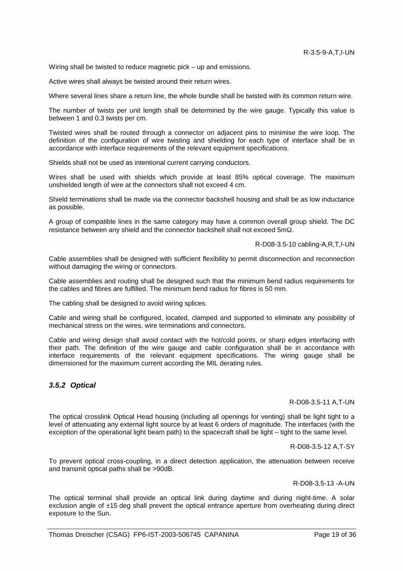
3.5.2 Optical
R-D08-3.5-11 A,T-UN
The optical crosslink Optical Head housing (including all openings for venting) shall be light tight to a level of attenuating any external light source by at least 6 orders of magnitude. The interfaces (with the exception of the operational light beam path) to the spacecraft shall be light – tight to the same level.
R-D08-3.5-12 A,T-SY
To prevent optical cross-coupling, in a direct detection application, the attenuation between receive and transmit optical paths shall be >90dB.
R-D08-3.5-13 -A-UN
The optical terminal shall provide an optical link during daytime and during night-time. A solar exclusion angle of ±15 deg shall prevent the optical entrance aperture from overheating during direct exposure to the Sun.

Thomas Dreischer (CSAG) FP6-IST-2003-506745 CAPANINA Page 20 of 36
As no measurements exist, yet, the current specification defines a set of “worst, worst case” values for optical background radiation levels that must be overcome by the optical link, both, during acquisition and tracking as well as during communications. Main contributors to such optical background levels are the Sun, sunlight reflected from the counter terminal’s blimp and clear blue sky. Minor contributions could stem from the Moon, planets and stars in the field-of-view of the optical detector. Latter are negligible in terms of magnitude when compared to the major contributors and therefore are not discussed further in this background specification.
R-D08-3.5-14 -A-UN
Background radiation from reflected sunlight
For the “worst, worst case” assumption with all sunlight incident on the partner blimp’s cover being reflected in diffuse way from a blimp’s cross section area along line-of-sight toward the receiving optical terminal with aperture DRx, about RLinkDistance away, the following radiometric expression applies:
diameterFoVthefillingAfor4/
][2
4/]//[
Blimplimtan
2
2
2
2
,
2
tantan
2
22
,det,lim
pBceLinkDis
Rx
EarthSun
SunSun
ceLinkDisceLinkDis
RxSunFoVectorpB
ARD
RR
L
WRFoV
RD
msrWL
⋅⋅
⋅⋅=
⋅⋅⋅
⋅⋅=Φ
−
π
ππ
λ
λλ
(3-2)
with the following symbols:
φλ, Blimp, detector FoV flux from reflected sunlight (albedo = 100%) in detector FoV, RLinkDistance away
Lλ, Sun solar radiance at center wavelength λ, here in 1nm optical bandwidth
ABlimp area of blimp cross section (approximated by area of an ellipse with r1 = 0.5 x r2)
R2Sun radius of the solar disk
R2Sun-Earth distance from sun to earth (=1 astronomical unit)
Figure 3-3: Worst case radiance from a blimp’s cover along line-of-sight, in 1 nm filter BW
Thomas Dreischer (CSAG) FP6-IST-2003-506745 CAPANINA Page 21 of 36
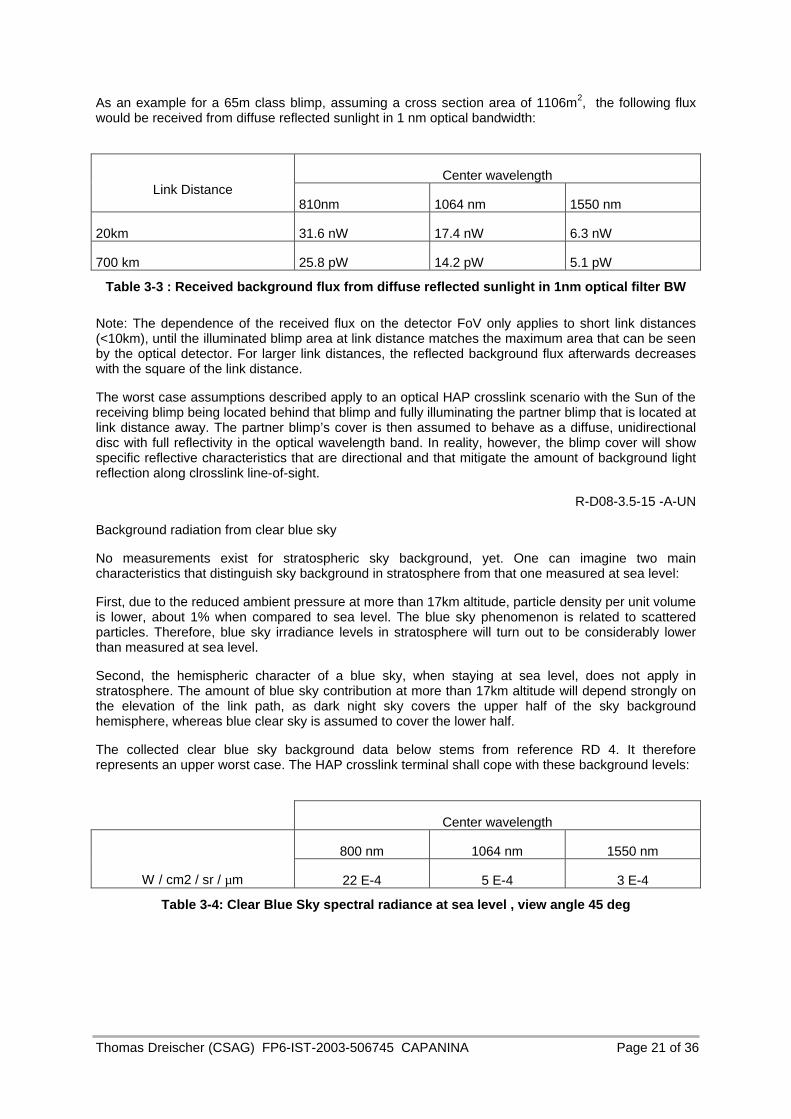
As an example for a 65m class blimp, assuming a cross section area of 1106m2, the following flux would be received from diffuse reflected sunlight in 1 nm optical bandwidth:
Center wavelength Link Distance
810nm 1064 nm 1550 nm
20km 31.6 nW 17.4 nW 6.3 nW
700 km 25.8 pW 14.2 pW 5.1 pW
Table 3-3 : Received background flux from diffuse reflected sunlight in 1nm optical filter BW
Note: The dependence of the received flux on the detector FoV only applies to short link distances (<10km), until the illuminated blimp area at link distance matches the maximum area that can be seen by the optical detector. For larger link distances, the reflected background flux afterwards decreases with the square of the link distance.
The worst case assumptions described apply to an optical HAP crosslink scenario with the Sun of the receiving blimp being located behind that blimp and fully illuminating the partner blimp that is located at link distance away. The partner blimp’s cover is then assumed to behave as a diffuse, unidirectional disc with full reflectivity in the optical wavelength band. In reality, however, the blimp cover will show specific reflective characteristics that are directional and that mitigate the amount of background light reflection along clrosslink line-of-sight.
R-D08-3.5-15 -A-UN
Background radiation from clear blue sky
No measurements exist for stratospheric sky background, yet. One can imagine two main characteristics that distinguish sky background in stratosphere from that one measured at sea level:
First, due to the reduced ambient pressure at more than 17km altitude, particle density per unit volume is lower, about 1% when compared to sea level. The blue sky phenomenon is related to scattered particles. Therefore, blue sky irradiance levels in stratosphere will turn out to be considerably lower than measured at sea level.
Second, the hemispheric character of a blue sky, when staying at sea level, does not apply in stratosphere. The amount of blue sky contribution at more than 17km altitude will depend strongly on the elevation of the link path, as dark night sky covers the upper half of the sky background hemisphere, whereas blue clear sky is assumed to cover the lower half.
The collected clear blue sky background data below stems from reference RD 4. It therefore represents an upper worst case. The HAP crosslink terminal shall cope with these background levels:
Center wavelength
800 nm 1064 nm 1550 nm
W / cm2 / sr / µm 22 E-4 5 E-4 3 E-4
Table 3-4: Clear Blue Sky spectral radiance at sea level , view angle 45 deg

Thomas Dreischer (CSAG) FP6-IST-2003-506745 CAPANINA Page 22 of 36
R-D08-3.5-16 -A-UN
Background radiation from direct exposure to the Sun
The optical terminal shall provide optical protection for the case of direct exposure to the Sun. The assumed flux levels from a Planck curve approximation (at 5770 K) are listed below.
Center wavelength
800 nm 1064 nm 1550 nm
W / m2 / sr 16820 9262 3328
Table 3-5: Solar radiance in 1nm optical BW
As an example for a 0.1m aperture, the total solar flux in all bandwidths amounts to 10.66 W (related to the solar constant at 5770K of 1.357kW/m2).
R-D08-3.5-17 -A-UN
Probability of non detection
The probability of non-detection shall remain below 10%, additionally taking into account the below specified probability of false alarm.
R-D08-3.5-18 -A-UN
Probability of false alarm
False alarms should be avoided as much as possible, as they must be fully processed by the mode switching logic and thereby add additional time to the acquisition process. The probability of false alarm shall remain below 10^-4.
Optical channel fading
The optical HAP crosslink terminal shall provide sufficient robustness in beam steering and in communication performance to establish and maintain an optical link during statistical periods of optical channel fading.
No measurements yet exist on optical channel fading in stratosphere. Therefore, initial assumptions were derived that are based on stratospheric optical transmission modelling for dedicated sets of wavelengths and receive/transmit aperture sizes. All modelling activity is based on atmospheric measurements in more than 2km altitude above sea level. The characteristic data specified below shall be understood as a design boundary that is TBC by measurement at a later stage.
3.5.3 Mechanical
R-D08-3.5-19 -A,T,I-UN
The launch environment is a combination of static acceleration and dynamic loads (vibration).
The optical terminal design shall accommodate this environment and satisfy all of the requirements of this specification in the presence of this environment.

Thomas Dreischer (CSAG) FP6-IST-2003-506745 CAPANINA Page 23 of 36
3.6 Environmental Considerations
3.6.1 Operating Temperature Range
R-D08-3.6-1-A-SY
The optical crosslink Terminal shall have an operating design temperature range (TBC):
Optical Head: - 35°C to +65°C
Electronic Unit : -10°C to +50°C
Laser Bench : -10°C to +25°C
The interface temperatures quoted are defined on the optical crosslink terminal side of the interface. The exact position of the reference point is TBD.
R-D08-3.6-2-A,T-SY
The optical crosslink terminal hardware housed within the spacecraft shall be designed to operate in a thermal environment with baseplate (measured on the spacecraft side of the interface) acceptance temperatures and radiation environment temperatures between -10°C and +25°C. The blimp radiation environment shall be assumed to have an effective emittance of 0.85 between –30ºC and +40ºC (TBC).
R-D08-3.6-3-A,T-SY
optical crosslink terminal hardware that is exposed to the environment exterior to the spacecraft shall be designed using the following external environmental parameters:
Environment temperature = -60°C (based on Trial 2 measurement)
Solar constant = 1326 to 1418 W/m2
Albedo constant = 0.35
Earth temperature = 260K
Altitude 17 – 20km
R-D08-3.6-4-A,T -SY
The non – operating design temperature range for the optical crosslink terminal is:
Optical Head: - 60°C to +75°C (TBC)
Electronic Unit: - 35°C to +70°C (TBC)
Laser Bench/Thermal Control: -35°C to +45°C (TBC)
The interface temperatures quoted are defined on the optical crosslink terminal side of the interface. The exact position of the reference point is TBD.
R-D08-3.6-5-A,T-SY
The storage temperature range for the optical crosslink terminal is –60°C to +50°C. The optical crosslink Terminal shall be capable of storage in a relative humidity maintained between 30% and 60% and above the local dew point.
The optical crosslink Terminal shall be capable to withstand these temperature ranges. The margins to be applied for qualification and acceptance are defined in section 3.3.2.4.
Thomas Dreischer (CSAG) FP6-IST-2003-506745 CAPANINA Page 24 of 36
3.6.2 Ambient Pressure
3.6.2.1 Lift-off Environment
R-D08-3.6-6 -A,T,I-UN
The optical crosslink terminal will experience the depressurisation specific to launch and the host platform. This shall be equivalent to a pressure change rate of:
Ambient to 0.1 Pa, within a period of TBC minutes, with a max. rate <TBC hPa/sec .
The optical crosslink terminal shall provide the performance at any ambient pressure between 550 torr and 812 torr (TBC).
3.6.2.2 Stratospheric Environment
R-D08-3.6-7-A,T,I-UN
The optical crosslink terminal shall demonstrate its functional performance in a stratospheric vacuum environment. That means:
Pressure = 1.0 hPa (based on Trial 2 measurement).
3.6.3 Acceleration
R-D08-3.6-8-A,T,I-UN
The maximum constant acceleration load for the optical crosslink terminal will be TBD.
3.6.4 Vibration
3.6.4.1 Launch vibration
R-D08-3.6-10-A,T-UN
The launch vibration shall be specified once the details of the blimp and launch track are known.
Acceleration measurements during Trial 2 in Kiruna could be helpful to get an indication on the environmental conditions, for instance when the blimp passes through the jet stream layer with strong wind forces.
The optical terminal design shall accommodate this environment and satisfy all of the requirements of this specification in the presence of this environment.
3.6.4.2 Microvibration
The loads expected by the mechanical and structural part in the operational (stratospheric) environment are generally covered by the quasi-static launch load acceleration and the micro-vibration generated by blimp equipment operations are not considered as structural design driver.
Nevertheless the unit shall be capable of meeting all specified performance requirements during exposure to the operational vibration environment defined by the TBD microvibration spectrum spectrum.
Thomas Dreischer (CSAG) FP6-IST-2003-506745 CAPANINA Page 25 of 36
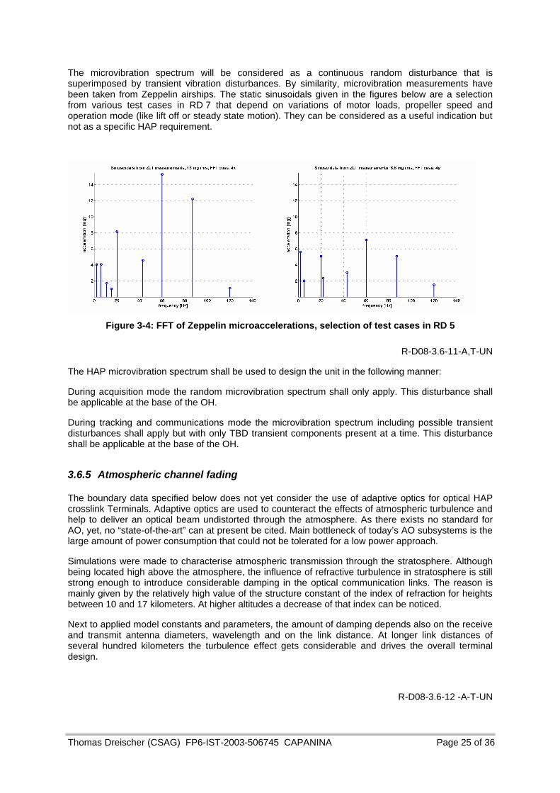
The microvibration spectrum will be considered as a continuous random disturbance that is superimposed by transient vibration disturbances. By similarity, microvibration measurements have been taken from Zeppelin airships. The static sinusoidals given in the figures below are a selection from various test cases in RD 7 that depend on variations of motor loads, propeller speed and operation mode (like lift off or steady state motion). They can be considered as a useful indication but not as a specific HAP requirement.
Figure 3-4: FFT of Zeppelin microaccelerations, selection of test cases in RD 5
R-D08-3.6-11-A,T-UN
The HAP microvibration spectrum shall be used to design the unit in the following manner:
During acquisition mode the random microvibration spectrum shall only apply. This disturbance shall be applicable at the base of the OH.
During tracking and communications mode the microvibration spectrum including possible transient disturbances shall apply but with only TBD transient components present at a time. This disturbance shall be applicable at the base of the OH.
3.6.5 Atmospheric channel fading
The boundary data specified below does not yet consider the use of adaptive optics for optical HAP crosslink Terminals. Adaptive optics are used to counteract the effects of atmospheric turbulence and help to deliver an optical beam undistorted through the atmosphere. As there exists no standard for AO, yet, no “state-of-the-art” can at present be cited. Main bottleneck of today’s AO subsystems is the large amount of power consumption that could not be tolerated for a low power approach.
Simulations were made to characterise atmospheric transmission through the stratosphere. Although being located high above the atmosphere, the influence of refractive turbulence in stratosphere is still strong enough to introduce considerable damping in the optical communication links. The reason is mainly given by the relatively high value of the structure constant of the index of refraction for heights between 10 and 17 kilometers. At higher altitudes a decrease of that index can be noticed.
Next to applied model constants and parameters, the amount of damping depends also on the receive and transmit antenna diameters, wavelength and on the link distance. At longer link distances of several hundred kilometers the turbulence effect gets considerable and drives the overall terminal design.
R-D08-3.6-12 -A-T-UN

Thomas Dreischer (CSAG) FP6-IST-2003-506745 CAPANINA Page 26 of 36
3.6.5.1 Fade duration
For obtaining temporal statistics, the choice of a value for windspeed is necessary. According to the available data from the University of Michigan [RD 5, RD 6] at the altitudes considered the wind ranges between 30 and 40 m/s. To take into account the different angles between the wind vector and the link direction, two velocities were considered: 5 m/s and 40 m/s.
With respect to the mean duration of the fades, they are in the range of some milliseconds for windspeed equal to 5 m/s and some tenths of millisecond for windspeed equal to 40 m/s [RD ].
R-D08-3.6-12 -A-T-UN
3.6.5.2 Fade probability
Fade probabilities were modelled up to minimum 10^-8. Some boundaries are given below in Table 3-6 for an optical crosslink between two terminals with Tx diameter of 35mm and Rx diameter of 135mm, using 1550nm wavelength.
Probability of fade
Link Distance 10^-1 10^-2 10^-4 10^-6
50 km 3 dB 4 dB 7 dB 12 dB
100 km 4 dB 7 dB 16 dB 25 dB
200 km 5 dB 15 dB 30 dB 40 dB
400 km 10 dB 20 dB 37 dB 50 dB
Table 3-6:Attenuation characteristics for 35mm Tx/135mm Rx aperture diameter, 1550nm wavelength
R-D08-3.6-12 -A-T-UN
3.6.5.3 Fade repetition frequency
For the described case, temporal fades occur at the given probability with maximum repetition rates of about 10 Hz at 5m/s wind speed and about 100 Hz at 40m/s wind speed.
3.6.6 Radiation
3.6.6.1 Total dose
R-D08-3.6-13 -A-T-UN
The ionising radiation environment affects a part slowly over the design life. The design is required to survive the total dose of ionising radiation accumulated in a maximum TBD period in stratospheric altitude. MIL standards for aircraft shall apply for total radiation dose levels (TBC).
The total dose for this altitude is supposed to be similar to the natural radiation on ground. The amount of the total dose to which a location is exposed is determined by the amount of spherical shielding surrounding the location.

Thomas Dreischer (CSAG) FP6-IST-2003-506745 CAPANINA Page 27 of 36
3.6.6.2 Particle Environment
3.6.6.2.1 Single Event Latchup
R-D08-3.6-14 -A-T-SY
Parts shall be selected which are immune to particle induced latchup. Latchup immune parts are defined as those parts having a latchup LET of greater than 100 MeV/(mg/cm2) (TBC).
3.6.6.2.2 Single Event Upset
R-D08-3.6-15 -A-T-SY
Electronic components used for the optical crosslink Terminal shall not be susceptible to single event upset, up to a threshold LET value of 100 MeV/(mg/cm2) (TBC).
3.6.7 Humidity
R-D08-3.6-16 -A-T-SY
Information on humidity conditions, especially during launch phase is required, in order to prevent icing of elements exposed to the outside like telescope or mirrors. Humidity measurements during Trial 2 in Kiruna could be helpful to get an indication on the environmental humidity conditions.
The optical terminal design shall accommodate this environment and satisfy all of the requirements of this specification in the presence of this environment.
3.6.8 Electromagnetic Compatibility
R-D08-3.6-17 -A-T-SY
In this section the electromagnetic environment is defined in which the optical crosslink Terminal shall be capable to operate.
Conducted Emissions
CEP Conducted Emissions on Primary Power Lines
CEP are the emissions appearing on each individual primary power line (including return line) for current emissions, and between any positive line and its corresponding return line for voltage emissions.
Current
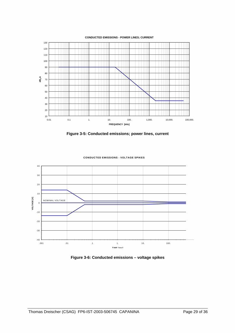
The conducted emissions on each individual DC primary power line shall not exceed the limits given in Figure 3-5.
Voltage Spikes
The voltage spikes produced on power lines by switching the power on/off or other operations of the optical crosslink Terminal shall not exceed the limits given in figure 3.5.9 - 2. Rise and fall times shall be longer than 1 microsecond.
Conducted Emissions on Secondary Power Lines
As for primary power.
CECM Conducted Emissions Common Mode, 30 – 50 MHz
Thomas Dreischer (CSAG) FP6-IST-2003-506745 CAPANINA Page 28 of 36
The CECM are the emissions appearing as current in the signal wire bundles. The measured levels are used as a basis for the susceptibility tests (margin verification).
Conducted Susceptibilities
CSP Conducted Susceptibilities on Primary Power Lines. No performance degradation in the optical crosslink Terminal shall occur by injecting interference on the power lines for the following levels:
Sinewave
Line to line injected levels shall be 2Vpp from 30 Hz to 50 kHz.
The requirement shall also be met when the signal source, adjusted to dissipate 50 Watts into a 0.5Ω load, cannot develop the required voltage at the best sample power input terminals and the test samples is not susceptible to the output of the signal source.
Transients
The injected transients superimposed on the nominal supply voltage shall TBD. The transient peak amplitudes shall be +TBD V. The rise time shall be less than 1 microsecond. Pulse repetition frequency shall be between 1 Hz and 10 Hz, for a duration of 5 minutes each polarity. The pulse generator output shall be calibrated across a 5Ω resistive load.
CS Conducted Susceptibility Secondary Power Lines
The equipment attached to a secondary bus voltage shall perform within nominal operating tolerances when injected transients, whose level is 6dB greater than those specified for the `Power Quality' of the secondary converter, are superimposed upon the secondary power leads of the converter.
CSCM Conducted Susceptibility Common Mode, 30 Hz – 50 MHz
No performance degradation shall occur in the optical crosslink Terminal by injecting interference current on the signal wire bundles. The injected levels shall be at least 6 dB higher than the equipment emission levels for common mode.
CMR Common Mode Rejection
No malfunction shall occur in the optical crosslink Terminal by injecting interference voltage between the signal reference and the ground plane.
The injected voltage levels shall be:
DC
The injected levels shall be: +5V
Sinewave 30 Hz to 1MHz
The injected levels shall be: 10Vpp from 30Hz to 10 kHz, falling 20dB/decade to 0.1 Vpp at 1 MHz.
Transients
The injected transients shall TBD for waveshape. The peak transients shall be + 5V. The rise time shall be less than 1 microsecond. Pulse repetition frequency shall be between 1 Hz and 10 Hz, for a duration of 5 minutes each polarity. The pulse generator output shall be calibrated across a 50Ω resistive load.
Thomas Dreischer (CSAG) FP6-IST-2003-506745 CAPANINA Page 29 of 36
CONDUCTED EMISSIONS - POWER LINES; CURRENT
10
20
30
40
50
60
70
80
90
100
110
120
130
0.01 0.1 1. 10. 100. 1,000. 10,000. 100,000.
FREQUENCY [kHz]
dB
µA
Figure 3-5: Conducted emissions; power lines, current
CONDUCTED EMISSIONS - VOLTAGE SPIKES
-40
-30
-20
-10
0
10
20
30
40
.001 .01 .1 1. 10. 100.
TIME [ms]
VO
LT
AG
E [
V]
NOMINAL VOLTAGE
Figure 3-6: Conducted emissions – voltage spikes

Thomas Dreischer (CSAG) FP6-IST-2003-506745 CAPANINA Page 30 of 36
Radiated Emission
RE – E Radiated Emission, E - Field
The optical crosslink Terminal shall not generate unintentional radiated emissions above the levels indicated, at a 1m distance from the unit and the harness:
Narrowband
Frequency range 14 kHz to 10 GHz: acc. MIL – STD – 461D, RE02 NB, for Class A2a equipment
Broadband
Frequency range 14kHz to 10 GHz: acc. MIL – STD – 461D, RE02 BB, for Class A2a equipment
RE – H Radiated Emission, H - Field
AC Fields
The radiated AC magnetic field emission from the optical crosslink Terminal and harness in the frequency range 30 Hz to 50 kHz, shall not exceed the limits shown in figure, measured at a distance of 7 cm.
DC Fields
The DC magnetic emission of the optical crosslink Terminal, in terms of magnetostatic moments, shall not exceed:
Optical Head : 0.2 Am2
Electronics Unit: 0.2 Am2
Radiated Susceptibilities
RS – E Radiated Susceptibility, E – Field
The optical crosslink Terminal shall operate normally when exposed to radiated fields of 2V/m, AM modulated 30% by a 1kHz sinewave, over the frequency range 14 kHz to 10 GHz.
RS – H Radiated Susceptibility, H – Field
AC Fields
No malfunction shall occur in the optical crosslink Terminal when exposed to an AC magnetic field of 140 dBpT from 30kHz to 2kHz, falling 40 dB/decade to 50 kHz.

Thomas Dreischer (CSAG) FP6-IST-2003-506745 CAPANINA Page 31 of 36
RADIATED EMISSIONS - E-FIELD NARROW BAND
20
30
40
50
60
70
10 100 1,000 10,000 100,000 1,000,000 10,000,000
FREQUENCY [kHz]
dB
µV/m
Figure 3-7: Radiated emissions – E-field narrow band
RADIATED EMISSIONS - E FIELD BROAD BAND
50
60
70
80
90
100
110
120
10. 100. 1,000. 10,000. 100,000. 1,000,000. 10,000,000.
FREQUENCY [kHz]
dB
µV/m
/MH
z
Figure 3-8: Radiated emissions – E-field broad band

Thomas Dreischer (CSAG) FP6-IST-2003-506745 CAPANINA Page 32 of 36
RADIATED EMISSIONS - H-FIELD
10
20
30
40
50
60
70
80
90
100
110
120
130
140
150
10 100 1,000 10,000 100,000
FREQUENCY [Hz]
dB
pT
Figure 3-9: Radiated emissions – H field
DC Fields
No malfunction shall occur in the optical crosslink Terminal when exposed to a DC magnetic field of 170 dBpT.
Lightning/Transient
No damage shall occur in the equipment when in the off condition and exposed to a magnetic field of 75 A/m (peak level), with a rise to peak value in 2 microseconds, and to fall to zero in 100 microseconds.
ESD Electrostatic Discharge
The optical crosslink Terminal shall not be susceptible to a 15 mJ arc discharge (13KV from a 140pF capacitor or equivalent) at a distance of 25 cm from the unit’s exterior surface.
The optical crosslink Terminal shall not be susceptible to a 15mJ arc discharge (13KV directly to the unit’s exterior surface.

Thomas Dreischer (CSAG) FP6-IST-2003-506745 CAPANINA Page 33 of 36
4. Summary and Conclusions
The current document compiles all boundary conditions, parameters and data required to analyse an optical crosslink link through the stratosphere. The values of these boundary parameters allow for the design of an optical inter-HAP crosslink terminal for stratospheric applications.
As this document has been written during a very early state of development, not all parameter values described in this interface specification could be based on existing data from flight platform hardware or from tables that contain measurement results of prototypes. Therefore, several assumptions had to be made on certain parameters like, for instance, optical propagation characteristics in a stratospheric transmission channel or the microvibration spectra and attitude characteristics that are expected on a blimp platform. If applicable, such parameters have mostly been assessed by similarity, for instance from optical atmospheric propagation measurements or from vibration characteristics of existing airship platforms.
At a later stage, the data compiled in this interface requirement document could be complemented by a dedicated optical crosslink performance specification and by an additional interface requirements document that is related to a specific high altitude stratospheric platform.
The set of key parameters in this document that are specific to the optical link performance have been verified by a system simulation. It has been run to obtain an optical crosslink performance evaluation that relates on the interface requirements specified herein.
The system simulation architecture is based on hardware experience at Contraves Space in the development of prototype optical terminals for inter-satellite crosslinks in space. The system simulation architecture has been adapted specifically for stratospheric crosslinks, mainly by including a stratospheric channel model that has been derived from atmospheric measurements on the Canary islands and measurements by the HRDI instrument on UARS [RD 5]. A second important adaptation was to exchange the host platform vibration profile and also the host attitude characteristics, according to measurements from a Zeppelin NT [RD 7] and by specifications from the HeliNET project [RD 1, RD 2].
The outcome of the system simulation showed that state-of-the-art technology can be used to realise an optical HAP crosslink terminal based on the interface requirement specifications given in this document, including a contingency margin on critical parameters.

Thomas Dreischer (CSAG) FP6-IST-2003-506745 CAPANINA Page 34 of 36
5. Annex A: Environmental data measured prior to Trial 2 execution
Figure 5-1:Capanina Trial 2 environmental data from a test flight, recorded one day before actual flight (courtesy by University of York, UK)
Thomas Dreischer (CSAG) FP6-IST-2003-506745 CAPANINA Page 35 of 36
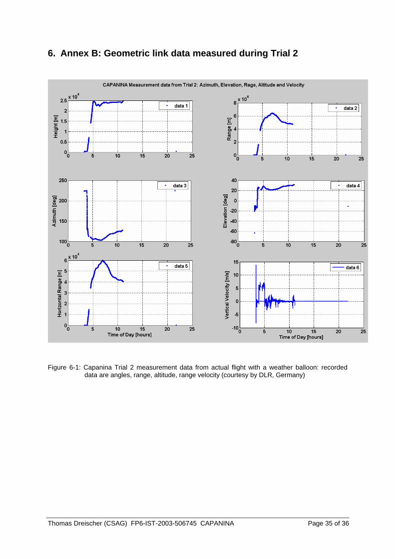
6. Annex B: Geometric link data measured during Trial 2
Figure 6-1: Capanina Trial 2 measurement data from actual flight with a weather balloon: recorded data are angles, range, altitude, range velocity (courtesy by DLR, Germany)
Thomas Dreischer (CSAG) FP6-IST-2003-506745 CAPANINA Page 36 of 36
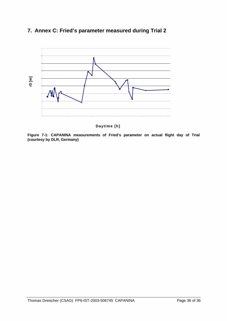
7. Annex C: Fried’s parameter measured during Trial 2
Daytime [h]
r0 [
m]
Figure 7-1: CAPANINA measurements of Fried’s parameter on actual flight day of Trial (courtesy by DLR, Germany)